Article

Numerical and Experimental Analysis of the Potential Fuel Savings and Reduction in CO Emissions by Implementing Cylinder Bore Coating Materials Applied to Diesel Engines

by
Sofia Orjuela Abril
1,*,
Carlos Pardo García
2 and
Jhon Pabón León
1
1
Programa de Administración de Empresas, Universidad Francisco de Paula Santander, Avenida Gran Colombia No. 12E-96 Barrio Colsag, San José de Cúcuta 540001, Colombia
2
Programa de Ingeniería de Sistemas, Universidad Francisco de Paula Santander, Avenida Gran Colombia No. 12E-96 Barrio Colsag, San José de Cúcuta 540001, Colombia
*
Author to whom correspondence should be addressed.
Submission received: 29 December 2020 / Revised: 12 February 2021 / Accepted: 14 February 2021 / Published: 18 February 2021
(This article belongs to the Special Issue Advances in Tribology and LCA Applied to Thermal Machines)

Abstract

:
Currently, internal combustion engines contribute to the problem of global warming due to their need to use products derived from fossil resources. To mitigate the above problem, this study proposes the use of coatings on the cylinder bore in order to reduce fuel consumption and polluting emissions. Therefore, in the present study a numerical model is developed in which the tribological behavior, heat fluxes, and leakage of the combustion gases in the chamber are considered to evaluate the influence of the coating. Nickel nanocomposite (NNC) and diamond-like carbon (DLC) coatings are considered in the study. The results demonstrate that the NNC coating produces a 32% reduction in the total friction force of the compression ring. The estimated maximum temperatures for the lubricating oil were 214, 202, and 194 °C for the DLC, steel, and NNC materials. Increasing the temperature in the DLC coating can cause a reduction in the tribological performance of the lubricant. The estimates made show that the implementation of the NNC coating allows a maximum reduction of 5.28 ton of fuel and 39.30 kg of CO emissions, which are based on the global fleet of diesel engines forecast for the year 2025 (corresponding to one hundred and eighty million engines) and a test time of 1800 s. The proposed numerical model allows future analyses to be carried out for other types of materials used as coatings. Additionally, the model can be expanded and adapted to consider other systems that involve friction processes in the engine.

Graphical Abstract

1. Introduction

Despite the harmful effects on the environment and human health, fuels derived from fossil products continue to be the main source of energy globally. However, alterations in climatic conditions have promoted actions to reduce the production of harmful emissions [1,2]. Additionally, the high dependence on fossil resources, especially in the automotive sector, causes an energy risk in the future because these types of resources are not renewable [3,4]. This situation has led to an interest in seeking alternatives that allow reductions in fuel consumption and minimize polluting emissions. In general, to achieve this purpose it is necessary to improve the efficiency of internal combustion engines (ICEs), which can be achieved through changes in mechanical design, new fuel alternatives, and operating conditions [5,6,7]. In the particular case of modern ICEs, it is observed that they are subjected to high thermal and mechanical conditions as a consequence of the high ratio between the power and the light weight of the engine components [8]. This causes an average loss of fuel energy of 9.5%, which is used to overcome the friction processes of the engine [9]. A significant portion of these friction losses is located in the piston rings, which represent between 40 and 55% of the total energy lost due to friction processes in the engine [10,11]. One way to improve the efficiency of engines is through tribological and thermal studies focused on the piston rings. This would allow an improvement in fuel economy and a reduction in polluting emissions [12,13,14].
Several investigations have experimentally studied the inefficiency in the piston ring assembly. However, there is a high difficulty in this type of methodology due to the modifications necessary for the measurement of friction losses under engine operating conditions [10]. Therefore, analysis using analytical models has been chosen, which allows a better understanding of the tribological behavior of piston rings [15,16]. Furthermore, this type of model allows the incorporation of studies focused on the continuity of the lubricant flow, regime, and transport. Studies of this type include the work developed by Mishra et al. [17,18], who formulated a thermo-elastohydrodynamic model for the study of the compression ring of the piston. The results indicated that the viscous effects of the lubricant could not be ignored. Additionally, they used elastohydrodynamic ring models to investigate the influence of ring asymmetry on friction losses [19]. Baker et al. [20] studied the elastodynamic behavior of flexible rings to evaluate their ability to adapt holes and prevent flue gas leaks. Morris et al. [21] constructed a thermal network model to estimate the contact temperature between the cylinder liner and the piston rings. The results showed that the model is in agreement with the findings of Mishra et al. [21]. Using the model, they investigated the change in temperature caused by friction in the rings. Rahmani et al. [22] concluded that fuel consumption is influenced by tribological characteristics and can be reduced by controlling the temperature inside the cylinder.
Modern ICEs are considered to be highly efficient heat engines. Therefore, to improve their efficiency, it is necessary to apply innovative technologies such as cylinder deactivation, surface texturing, the heat treatment of exhaust gases, and the use of advanced coatings [23,24,25]. The use of coatings applied to ICE engines has been studied largely experimentally for different operating conditions, including standard conditions, cold start, and wear [26]. The investigations carried out show that the application of surface coatings influences tribological and thermal behavior. Therefore, they can be used to minimize the wear problems produced in engine contact areas [27]. Dahotre and Nayak [28] investigated a coating based on graphite, Al2O3, and SiC. It was observed that this type of coating improves the lubrication properties and wear resistance of surfaces. In the case of nickel nanocomposite (NNC) coatings, improvements have been obtained in the tribological characteristics of cylinder holes [27]. Rejowski et al. [29] reported that diamond-like carbon (DLC) coatings reduce friction by 2.5%.
The pistons of ICE engines are exposed to high mechanical and thermal loads [30]. Therefore, wear is one of the main causes of engine piston failure [31]. Specifically, the cylinder liner supports high friction and wear forces as a consequence of lateral thrust forces [32]. Typically, pistons are made of aluminum-silicon alloys [33]. Improved engine energy efficiency requires better performing pistons [34]. However, the wear resistance of aluminum alloys is limited [35]. In order to improve the durability and reliability of the pistons in the engines, different coatings have been implemented based on carburized, spray-on, nitrided, microarc oxidation, and composite materials, among others [36,37,38,39]. Nguyen et al. [40] used a titanium nitride coating to increase resistance to corrosion and wear. Chen et al. [41] investigated the development of a self-lubricating carbide layer by electrical discharge. Wang et al. [42] studied iron-based coatings applied to Al-Si alloys. The results show a better wear resistance compared to Al-Si alloys.
Previous studies demonstrate the benefits of coating technology as an indirect means of minimizing the problems associated with the consumption of fossil resources and environmental impact. Additionally, the application of coatings implies an improvement in fuel economy. Due to this, it is necessary to develop tribological studies focused on quantifying the impact of this type of technology. However, the literature does not generally evaluate the effect of applying coatings on reducing emissions and saving fuel.
Due to the above, in the present study a numerical model is proposed to evaluate the effect of coating materials on reducing fuel and polluting emissions. For this, a model is developed in which the tribological behavior, heat flows, and exhaust of the combustion gases are considered. The study analyzes the properties of nickel nanocomposite (NNC) and diamond-like carbon (DLC) materials, which are compared with the steel surface of the cylinder liner. The study is based on the characteristics of a single-cylinder diesel engine. In this way, it seeks to contribute to the development of a methodology that allows estimating the effects of coating materials on the tribological characteristics, power loss, and thermal characteristics between the contact of the compression rings and the cylinder liner. Additionally, it seeks to evaluate the impact of this type of technology on fuel consumption and CO emission levels. This allows us to search for an improvement in the fuel economy of internal combustion engines.

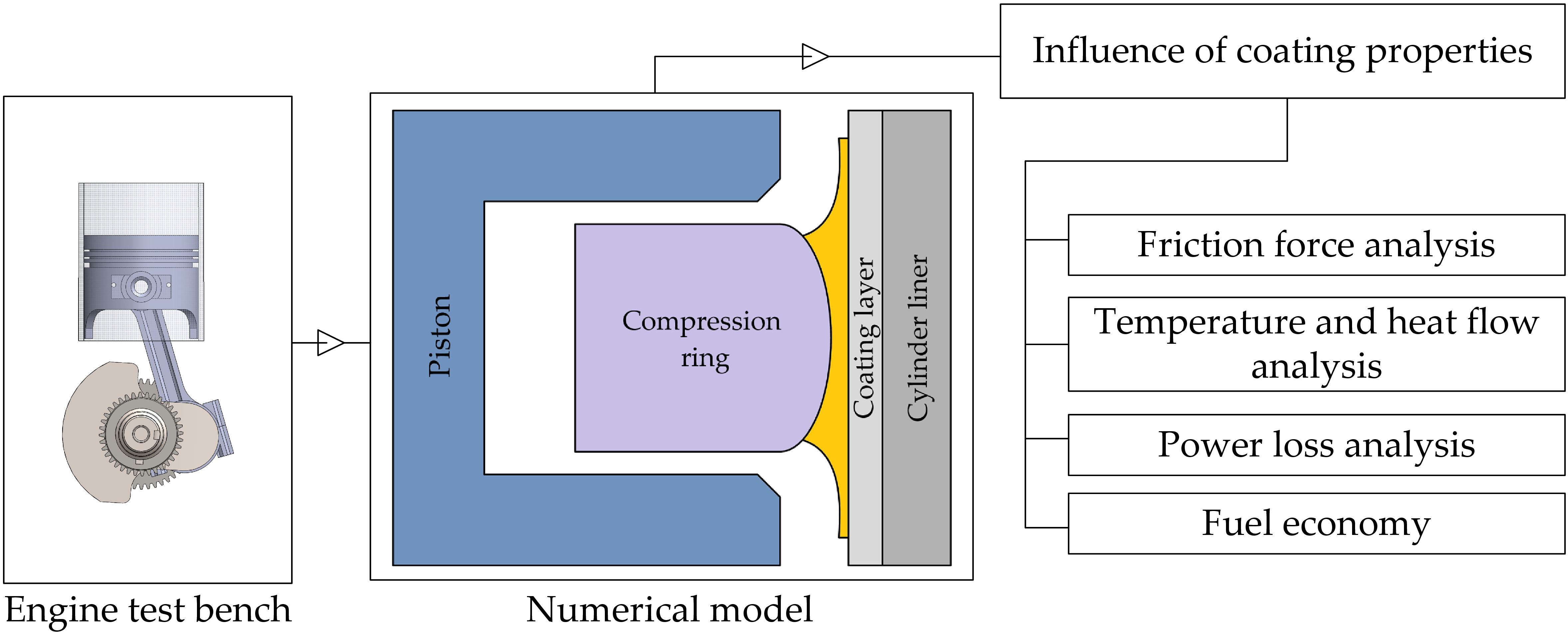
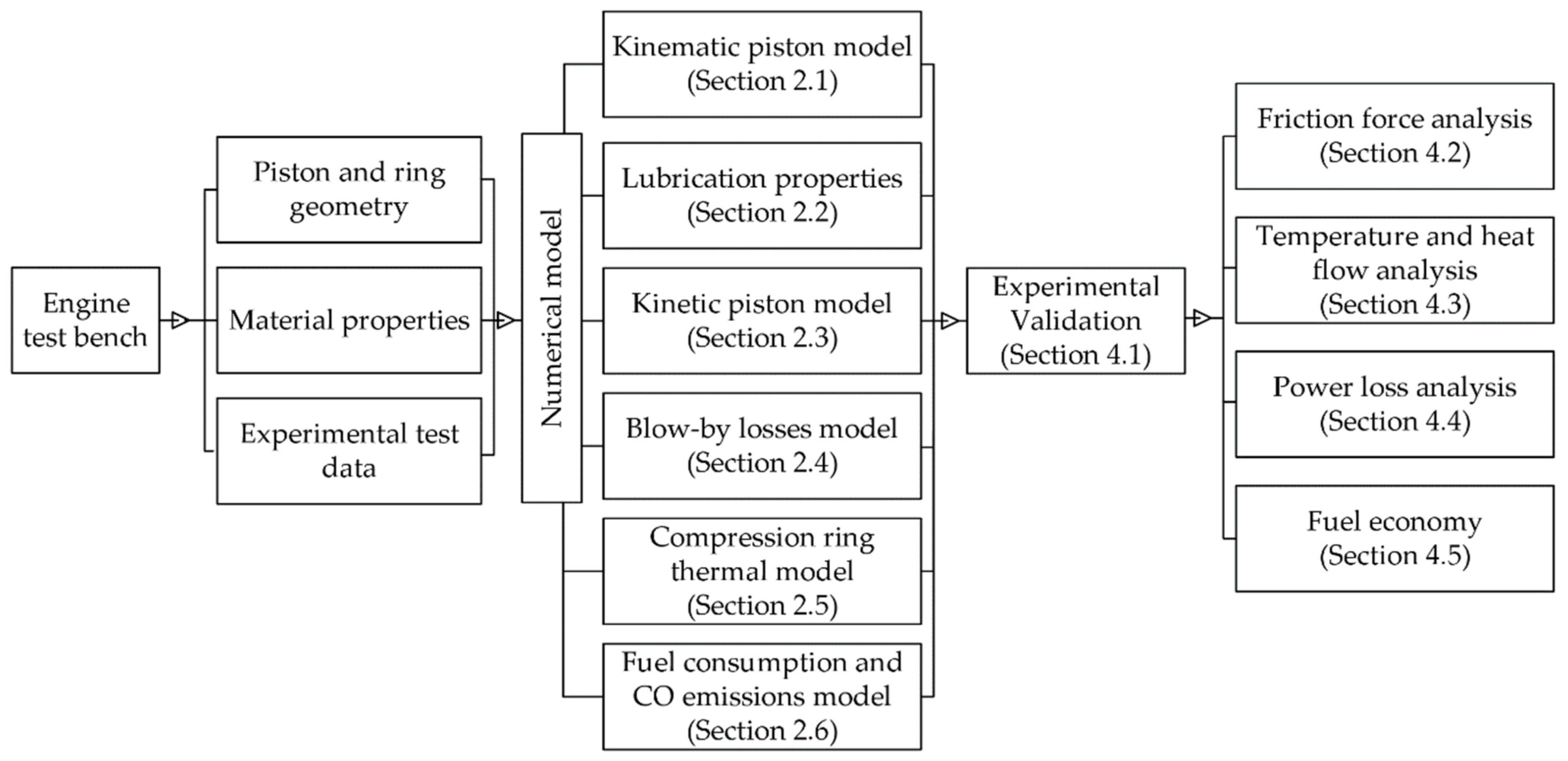
2. Mathematical Model

To evaluate the effect of the properties of nickel nanocomposites (NNC) and diamond-like carbon (DLC), a mathematical model is developed. The model used is composed of kinematic analysis, lubricant properties, kinetics, leakage, and thermal losses applied to the compression ring. Each of these analyses is described in the following sections.

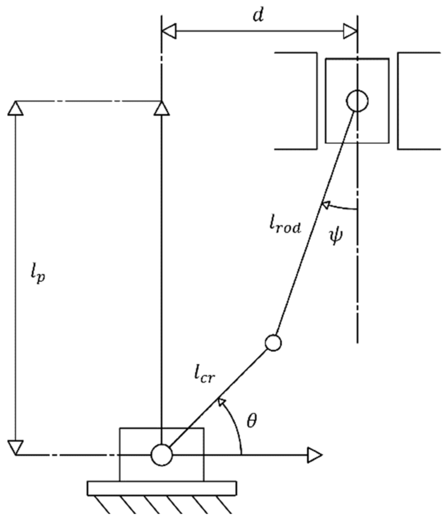
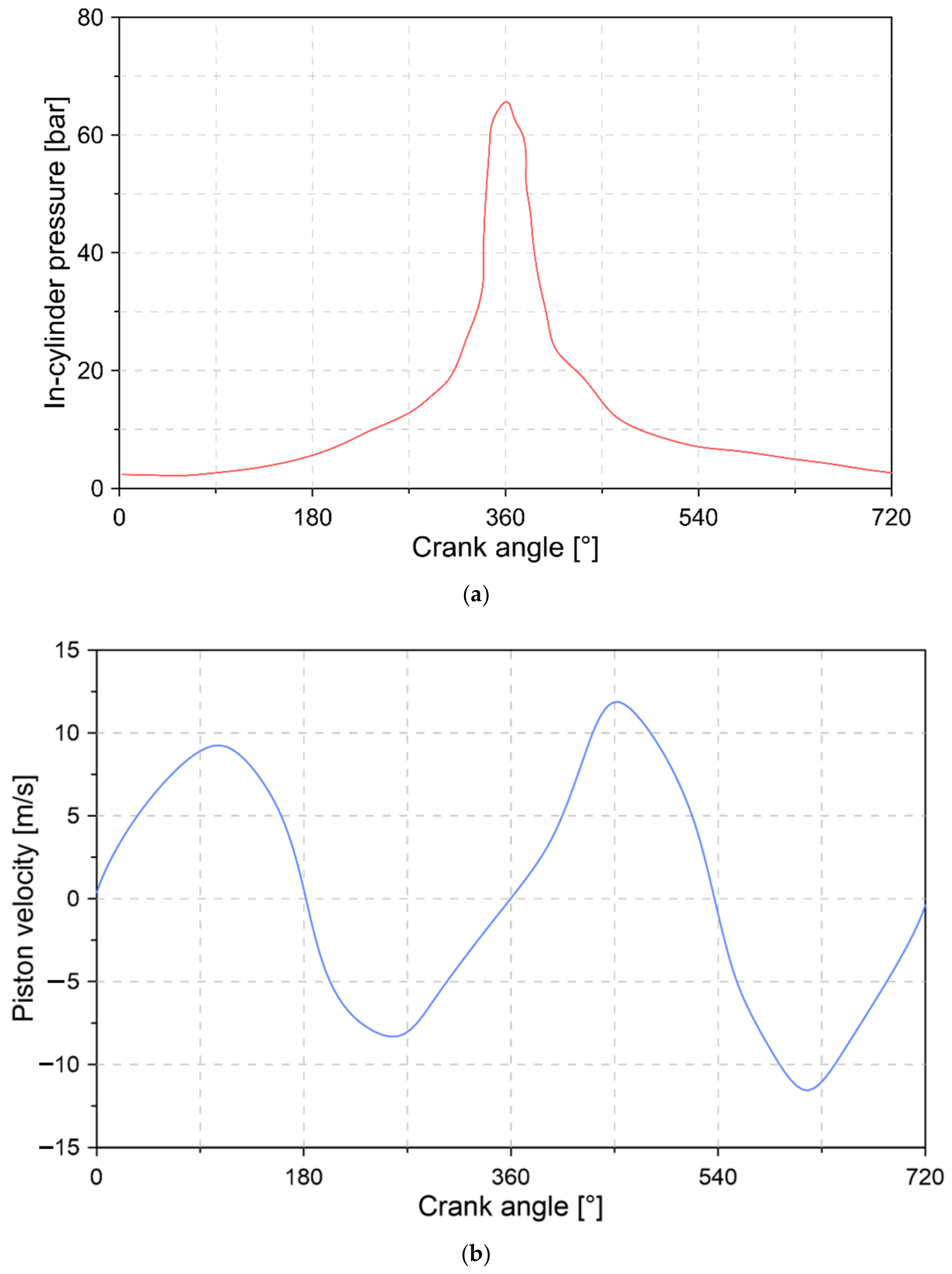
2.1. Kinematic Piston Model

To study the behavior of the compression ring, the primary movement that the piston experiences throughout the combustion cycle is described. This analysis is carried out considering the crankshaft—connecting rod—piston components as a sliding mechanism [43]. From the above, the displacement, velocity, and acceleration of the piston as functions of the crankshaft angle are determined. The description of the movement and the geometric parameters of the mechanism are shown in Figure 1.
Through an algebraic analysis, the velocity v p and acceleration a p of the piston are calculated by solving the system of equations shown below [44].
l c r × ω c r × sin θ l c r × ω c r × cos θ = l r o d × sin ψ 1 l r o d × cos ψ 0 ω r o d / p v p ,
L c r × ω c r 2 × cos θ L r o d × ω r o d / p 2 × cos ψ L c r × ω c r 2 × sin θ + L r o d × ω r o d / p 2 × sin ψ = L r o d × sin ψ 1 L r o d × cos ψ 0 α r o d / p a p ,
where l c r is the longitude of the crankshaft, l r o d is the longitude of the connecting rod, θ is the angle of rotation of the crankshaft, ω c r is the angular velocity of the crankshaft, ω r o d / p is the angular velocity relative to the motion between the connecting rod and the piston, and ψ is the angle formed between the axis of movement of the connecting rod and the piston. This last parameter is calculated using Equation (3):
ψ = sen 1 d L c r × cos θ L r o d ,
where d is the horizontal distance between the axis of movement of the piston and the crankshaft. By solving Equations (1) and (2), the velocity and acceleration of the connecting rod are determined, allowing for the velocity and acceleration of the piston to be calculated as a function of the crankshaft angle.

2.2. Lubrication Properties

A two-phase condition is established for the mathematical model in the compression ring, which is distributed by 10% air and 90% lubricating oil. The initial thickness of the lubrication film is set at a value of 5 μ m . This value is based on the empirical research developed by Lyubarskyy et al. [45]. The properties of the lubricating oil used are described in Table 1.
Since the dynamic viscosity and density of the lubricating oil changes with pressure and temperature conditions, mathematical functions are defined to account for the variation in lubricant properties. In the case of density, the relationship established by Dowson and Higginson [46] is used, which is shown in Equation (4):
ρ = ρ ο ρ o × β × T T ο + 6 × 10 10 · ρ ο ρ o × β × T T ο × P P ο 1 + 1.7 × 10 9 × P P ο ,
where P and β are the pressure in the combustion chamber and the coefficient of thermal expansion. The subscript o indicates the environmental conditions.
For the change in the viscosity of the lubrication oil, the Houpert equation [47] is used, as described by Equation (5).
η = η o e ln η o η × 1 + P P ο c p Z T 138 T o 138 S ο 1 .
where c p and η are the model constants, defined as 1.98 × 10 8   Pa and 6.31 × 10 5   Pa · s , respectively. S and Z are the thermo-viscosity indices and lubricant piezo-viscosity, which are defined by Equations (6) and (7) [48].
S = β o T o 138 ln η o η ,
Z = α o c p ln η o η ,
where β ο and α ο are the thermo-viscosity and piezo-viscosity at environmental conditions, respectively.

2.3. Kinetic Piston Model

The lubricating oil that coats the piston compression ring supports the ring loads. Therefore, the frictional forces are affected by the lubrication properties and the height of the lubrication film. To determine the forces acting on the compression ring, it is necessary to solve the equations that govern the fluid mechanics of the lubricant. Due to the above, the Reynolds equation is used, which establishes a relationship between the height of the film and the pressure of the lubricating oil. In the specific case of the present study, a two-dimensional approach is used, which implies that the lubrication parameters are found as a function of the piston position. From this condition, the Reynolds equation is defined as shown in Equation (8) [49].
y h 3 P y = 6 η v p h y + 12 η d h d t ,
where h is the height of the lubrication film below the profile of the compression ring.
For the analysis of the radial and axial forces applied to the piston compression ring, the following considerations are established:
  • Radial inertial forces are neglected due to the stiffness of the piston body, which is the consequence of the proper adjustment of the inner diameter of the ring [50].
  • The axial damping force is determined by means of the Reynolds equation since this is the main equation used in the literature to describe the hydrodynamic behavior between the ring and the cylinder liner [45].
  • The pressure and behavior of the combustion gases are considered in a steady state.
  • Flow processes are considered isothermal. This consideration is appropriate because of the relatively low velocity of flow over the compression ring groove [51].
The aforementioned considerations are normally implemented in the literature for the analysis of piston ring dynamics [50].
In Equations (9) and (10), the dynamic forces applied to the compression ring in the axial and radial direction of the piston are described.
F h y d r o , a x i a l + F f r i c , a x i a l + F g a s , a x i a l = m r × d 2 y d t 2 ,
F h y d r o , r a d i a l + F f r i c , r a d i a l + F g a s , r a d i a l = m r × d 2 x d t 2 ,
where F h y d r o , F f r i c , and F g a s are the damping force of the lubrication film, the friction force due to the interaction between the ring surface and the cylinder liner, and the force due to the combustion gases. m r is the mass of the compression ring.
The friction force ( F f r i c ) is made up of two components, which correspond to the asperity force F a s p caused by the lubricant’s shear effect and the hydrodynamic force F h y d r o caused by the lubricant’s viscosity, as shown in Equation (11).
F f r i c = F a s p + F h y d r o .
The asperity force F a s p is defined by Equation (12) [52].
F a s p = c f b a P c d x ,
where P c and c f are the asperity contact pressure and pressure coefficient of boundary shear. P c is calculated by Equation (13).
P c = 16 2 π 15 × σ c 2 + σ r 2 × r c 2 × η 2 × E × σ c 2 + σ r 2 1 / 4 × F 5 / 2 r c 1 / 2 ,
where σ r , σ c , E , and r c are the surface roughness of the compression ring, the surface roughness of the cylinder liner, the composite Young’s modulus between the cylinder liner and the compression ring, and the radius of the curvature of asperities. F 5 / 2 is the commutation function calculated by means of Equation (14).
F 5 / 2 = 4.4068 × 10 5 4 H s 6.804 ,       H s < 4 0 ,       H s 4 ,
where H s is the film thickness ratio. The composite Young’s modulus between the cylinder liner and compression ring E is calculated by means of Equation (15) [53].
2 E = 1 ϑ c 2 E c + 1 ϑ r 2 E r ,
where E and ϑ are the elastic modulus and the Poisson ratio. The subscripts c and r indicate the cylinder liner and compression ring, respectively.
The hydrodynamic force shown in Equation (16) is determined, as shown in the following equation:
F h y d r o = b a v p η h + h 2 P x d x .
The power loss due to friction processes is calculated using Equation (17) [54].
P l o s s = h 3 12 η P x 2 d A + η · v p 2 h d A .

2.4. Blow-By Losses Model

Equation (18) and (19) is used to determine the flow of flue gas leaking from the combustion chamber through the piston [55].
m ˙ b = P c c P u p s 1 / γ × P c c × c d × A v R × T i n 1 / 2 × 2 γ γ 1 × 1 P c c P u p s γ 1 / γ 1 / 2 ,           P c c P u p s > 2 γ + 1 γ / γ 1 ,
m ˙ b = γ 1 / 2 × P c c × c d × A v R × T i n 1 / 2 × 2 γ + 1 ( γ + 1 ) / 2 γ 2 ,           P c c P u p s 2 γ + 1 γ / γ 1 ,
where T i n is the temperature of the fuel at the inlet valve, P c c is the combustion chamber pressure, P u p s is the upstream pressure wave, R is the gas constant, and c d is the coefficient of discharge c d = 0.55 . A v and γ are the engine valve area and the specific heat ratio, which are calculated using Equations (20) and (21) [56].
A v = π · D v 2 4 ,
γ T = 1.46 1.63 × 10 4 T + 4.14 × 10 8 T 2 ,
where D v is the diameter of the valve D v = 26   mm .

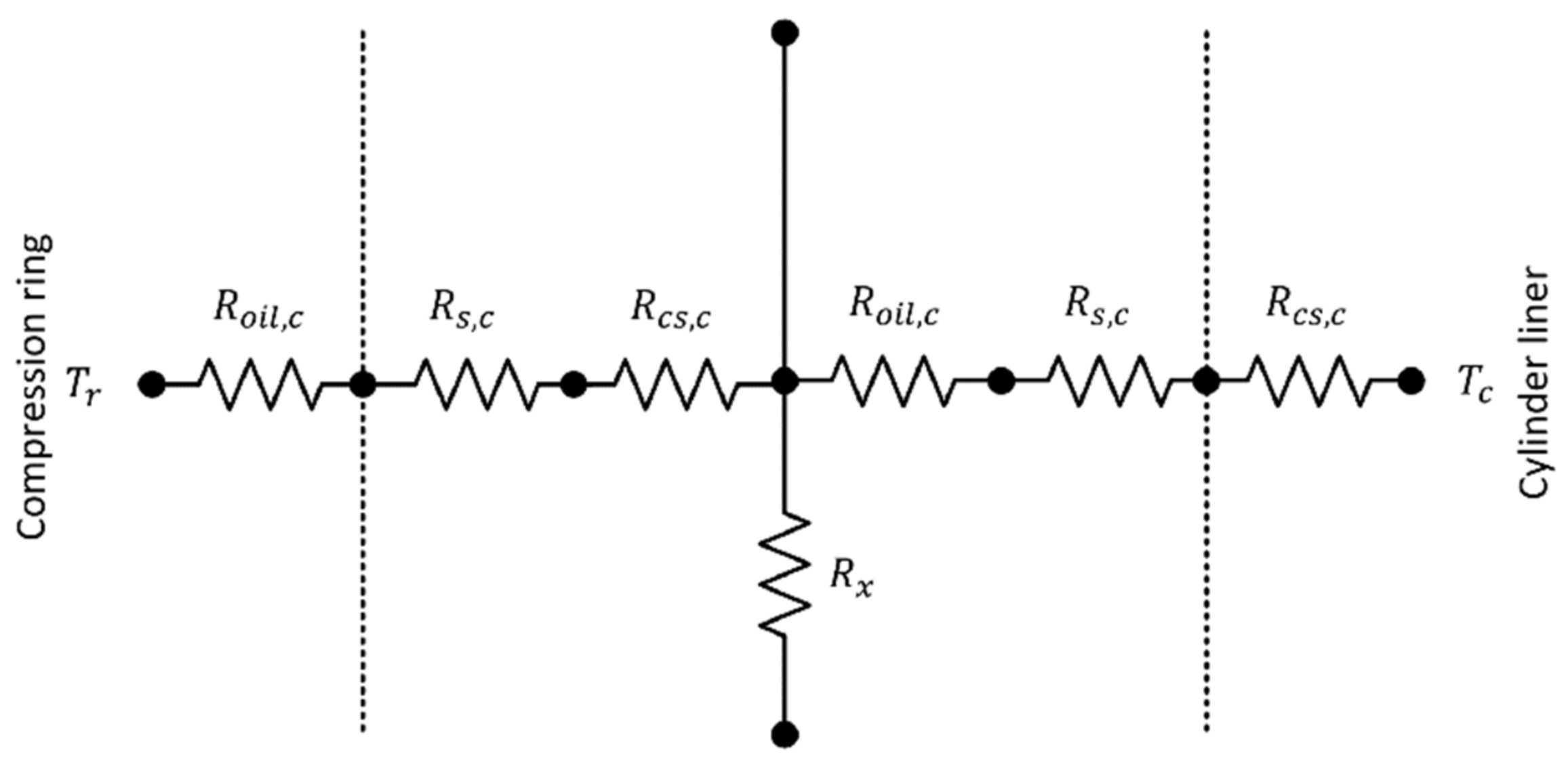
2.5. Compression Ring Thermal Model

Figure 2 shows the model for the thermal analysis of the compression ring of the piston in order to observe the influence of the coating on heat transfer. For the analysis, it is considered that all the heat generated is a consequence of power losses due to friction processes ( Q ˙ t = P l o s s ) .
The total heat generated is dissipated through the coated surface of the compression ring Q ˙ r , by convection transfer to the lubricating oil Q ˙ l u b , and through the coated surface of the cylinder liner Q ˙ c . The distribution of the total heat generated is shown in Equation (22).
Q ˙ t = P l o s s = Q ˙ r + Q ˙ l u b + Q ˙ c .
The heat flow is transmitted through different thermal resistances, which correspond to conduction through lubrication oil R l u b , convection through contact surfaces R s , and conduction through coated surfaces R c s . Each of these resistances are calculated using the following equations.
R l u b = h 2 k l u b · A ,
R s = 1 h c · A ,
R c s , i = S f , i k i · A   ,   i = c , r ,
where h is the thickness of the lubrication film, h c is the convection coefficient, k l u b is the thermal conductivity of the lubricant, and S f , i is the equivalent length. The subscripts c and r refer to the cylinder bore coating and compression ring.

2.6. Fuel Consumption and CO Emission Model

The mass flow of fuel is determined by Equation (26).
m ˙ f = m ˙ A F r r + 1 ,
where A F r r is the real air/fuel ratio, which is obtained from data obtained through experimental tests. m ˙ is the mass flow from the fuel–air mixture. The energy of the fuel flow is calculated by means of Equation (27).
E ˙ f = m ˙ f · Q L H V ,
where Q L H V is the lower calorific value of the fuel. The variation in the fuel flow is calculated using Equation (28).
m ˙ f = E ˙ l o s s Q L H V ,
where E ˙ l o s s is the variation in the loss energy. This term will be influenced by the characteristics of each coating.
The index of CO emissions is calculated by means of Equation (29).
C O = e 8.395 + 5.518 ϕ 2 ,       ϕ < 1 2.725 + 2.78 ϕ ,       ϕ 1 ,
where ϕ is the equivalence relation, which is shown in Equation (30).
ϕ = A F s s   A F r r   ,
where (A/F) is the stoichiometric air/fuel ratio, defined by Equation (31).
A F s s = 35.56 · 4 + x 12.011 + 1.008 x ,     x = b a , C a H b .

3. Numerical Methodology

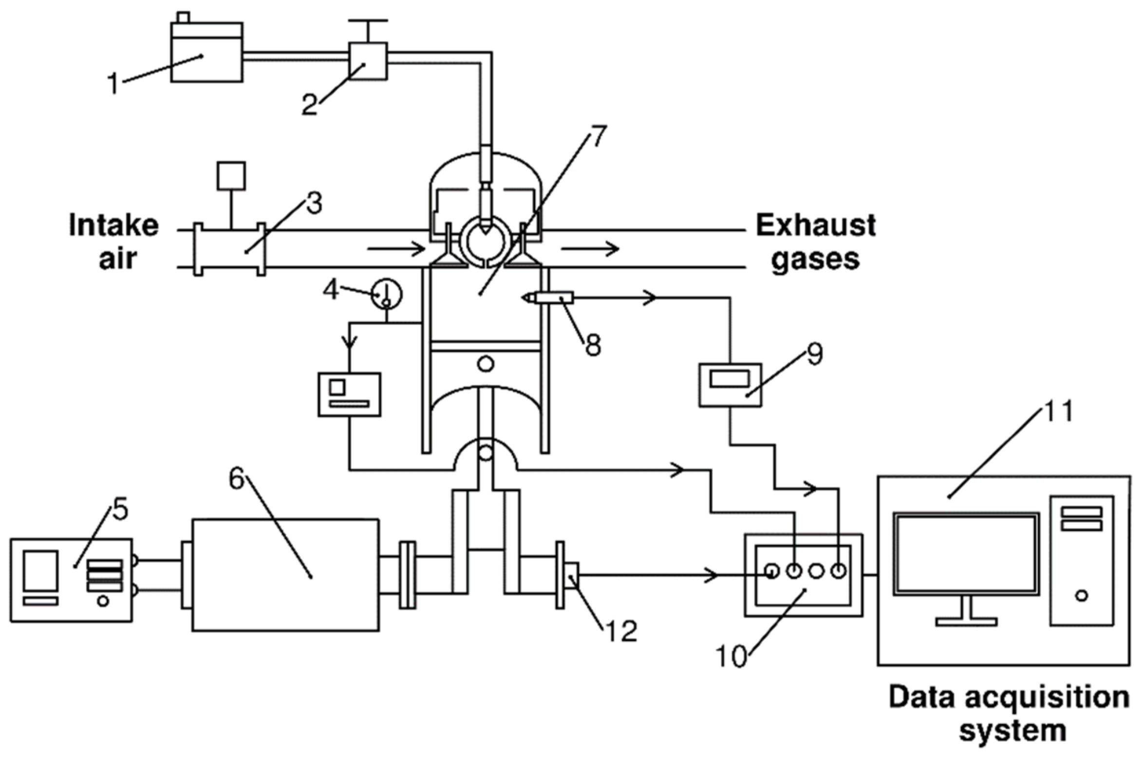
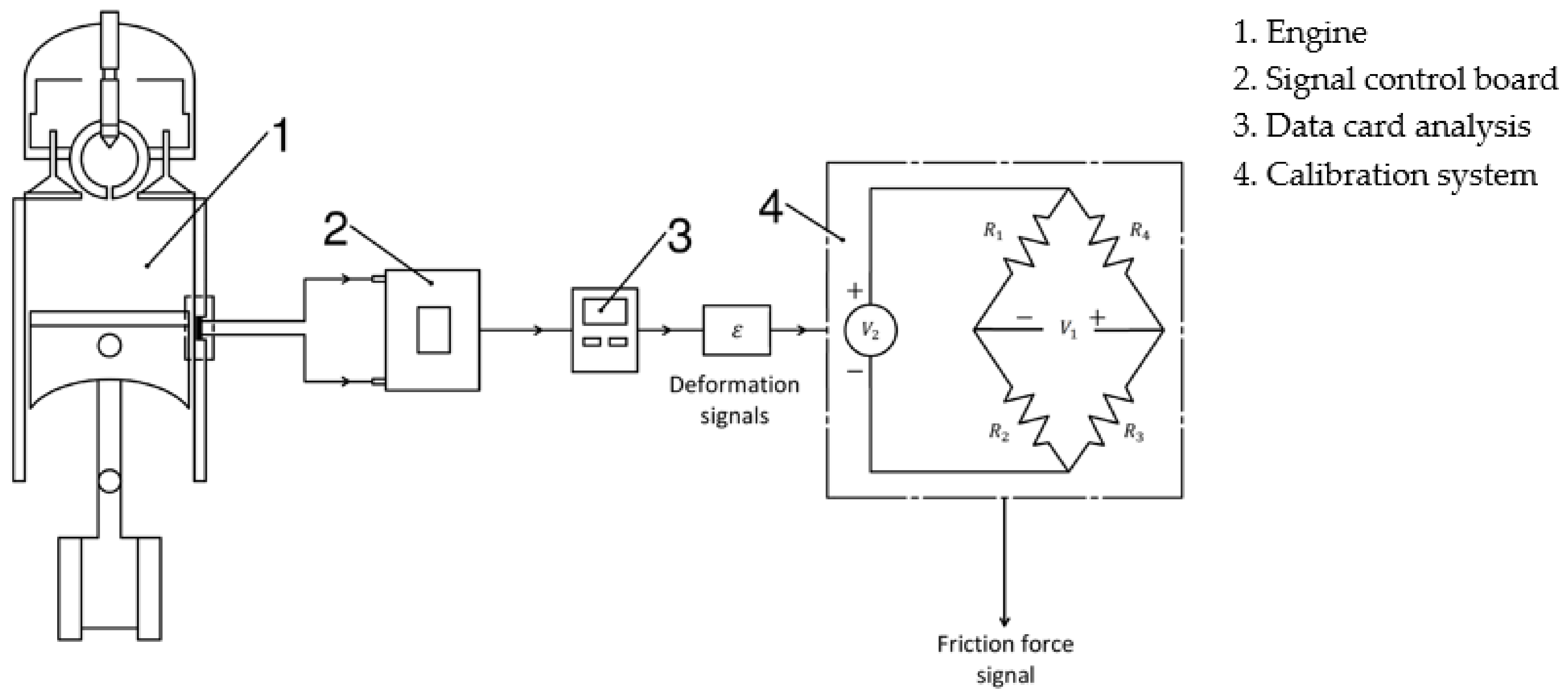
3.1. Experimental Test Bench

Figure 3 shows the experimental test bench used as a reference for the numerical model.
The test bench consists of a single-cylinder, four-stroke, natural injection diesel engine. Table 2 shows the technical characteristics and geometric properties of the engine.
An alternator coupled to the shaft is used to control the load conditions of the diesel engine. The intake air flow measurement is conducted by a mass flow sensor (BOSCH OE-22680 7J600). The pressure inside the cylinder is measured by a piezoelectric pressure transducer (KISTLER 7063-A) and a load amplifier (KISTLER 5015). The fuel flow is calculated using a gravimetric meter (OHAUS—PA313). To ensure synchronization between the combustion pressure signal and the crankshaft rotation angle, a TDC sensor (Top Dead Center) and angle encoder (BECK ARNLEY 180-0420) are used. The information from each of these sensors is used as input data for the model. Figure 4 describes the behavior of the combustion pressure and the velocity of the piston for a combustion cycle.

3.2. Uncertainty Analysis

In the development of experimental measurements, there are factors that induce errors in the measurement process, such as instrument calibration, environmental conditions, and human error, among others. Due to this situation, it is necessary to guarantee the reliability of the data obtained from the measurement. For this, an uncertainty analysis is carried out, in which the systematic error U s y s , x i due to the nature of the instrument and the random error U r , x i due to uncontrollable external factors are considered. The calculation of the random error is performed by statistical analysis, as shown in Equation (32) [57].
U r , x i = 1 n 1 / 2 × 1 n 1 × i = 1 n q i q ¯ 2 1 / 2 .
The total uncertainty U t is calculated from the square root of the mean due to random error and systematic error, as shown in Equation (33) [57].
U t = U r , x i 2 + U s y s , x i 2 1 / 2 ,
where x i is the best estimate of a set of measurements ( q 1 ,   q 2 ,   q 3 ,   ,   q n ) and n is the number of measurements made for each variable. For the research, a total of three repetitions n = 3 were carried out, since an increase in the measurements can increase the error in the measurement due to external factors such as the change in environmental conditions. The technical characteristics and the uncertainty of the measuring instruments are shown in Table 3.

3.3. Material Properties

For the study, the influence of the diamond-like carbon (DLC) and nickel nanocomposite (NNC) coatings on the cylinder bore is evaluated. The properties of these coatings are obtained from the information provided by the manufacturer [58]. The cylinder bore material is steel. The thermo-mechanical properties of the above materials are shown in Table 4.
In the case of the compression ring, it is coated with titanium nitride (TiN). The thermo-mechanical properties of the compression ring material are shown in Table 5.
Each of the thermo-mechanical properties shown in Table 4 and Table 5 directly affects the kinetics and thermal conditions of the piston. The above is due to the fact that these properties directly influence the asperity force and the heat flows within the combustion chamber, as shown in Equations (12), (13), (15), and (21).

3.4. Numerical Procedure

To solve the system of equations described in Section 2, the solver ode45 of the MATLAB software is used. In Figure 5, the diagram of the process used to analyze the influence of the coating on the cylinder bore is described.
The geometric characteristics of the test engine and the data recorded through the measurement instruments are used as input data in the numerical model. Based on this information, calculations are made to define the dynamic conditions of the compression ring, physical properties, heat flows, and leakage gas losses, which are shown in Section 2. Before analyzing the results, a validation of the estimates is made by the model through a comparison between the friction force of the piston obtained by the model and experimentally. This analysis is detailed in Section 4.1. Finally, the numerical model is used to study the influence of the coating on the cylinder bore.
For the validation of the numerical model, a comparison is made between the friction force supported by the piston for different angular positions of the crankshaft, obtained through the model and the experimental tests.
The measurement of the friction force is carried out by means of a strain gauge sensor, which allows the measurement of deformation and tension in the cylinder liner. For the installation of the sensor, a portion of the cooling fins of the engine is removed and fixed by means of a high-temperature adhesive. The sensor sends a pulse signal that indicates the deformation produced in the cylinder liner due to the passage of the piston. The sensor characteristics are shown in Table 6. The measurement process is shown in Figure 6.
The friction force is calculated using Equations (34) and (35) [61].
V 1 V 2 = ε · G f 2 1 2 + ε · G f ,
F f r i c = ε × A s × E c ,
where E c , ε , A s , G f ,   and V are Young’s modulus of the cylinder liner, the longitudinal strain, the area of the strain gauge sensor, the sensor calibration factor G f = 2 , and the voltage.
Since the deformation measured by the sensor includes the thermal deformation caused by the elevated temperatures of the chamber, a filtering process is carried out. For this, a coefficient of thermal expansion of 24 µstrain/°C is considered [62]. In this way, it is ensured that the measured deformation is a consequence of the friction process.

4. Results and Discussion

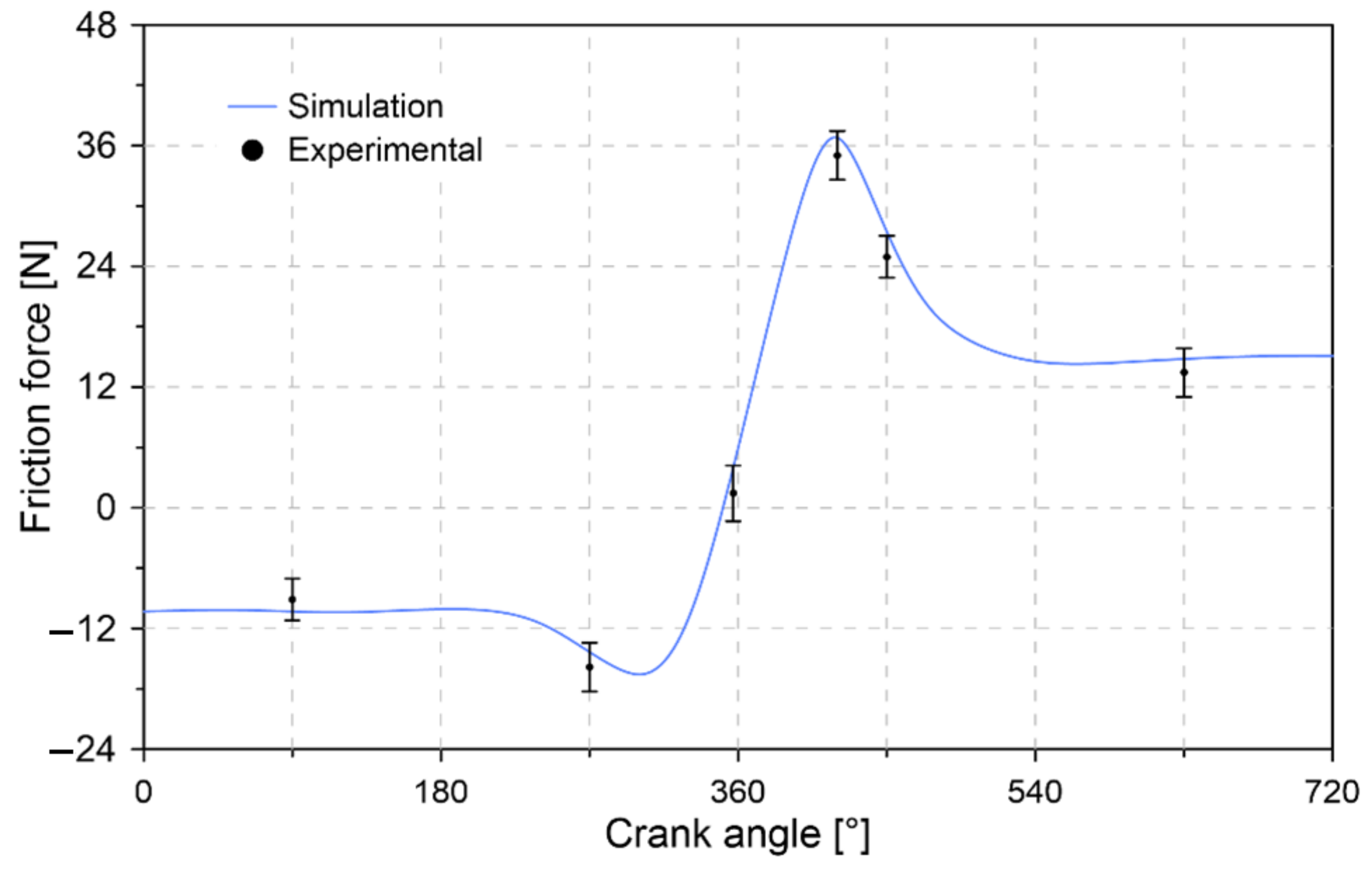
4.1. Experimental Validation

The results of the comparison between the experimental tests and the model estimates are shown in Figure 7.
The results show that the numerical model allows us to describe the behavior inside the combustion chamber. The relative error between the simulation and the mean value of the experimental data is 8%. However, when considering the minimum and maximum values of the measurement range for each point, maximum errors of 24% and 30% were obtained. The methodology used and the errors obtained are considered acceptable to analyze the behavior of the piston compression ring due to the difficulty of isolating the ring under engine operating conditions [63].

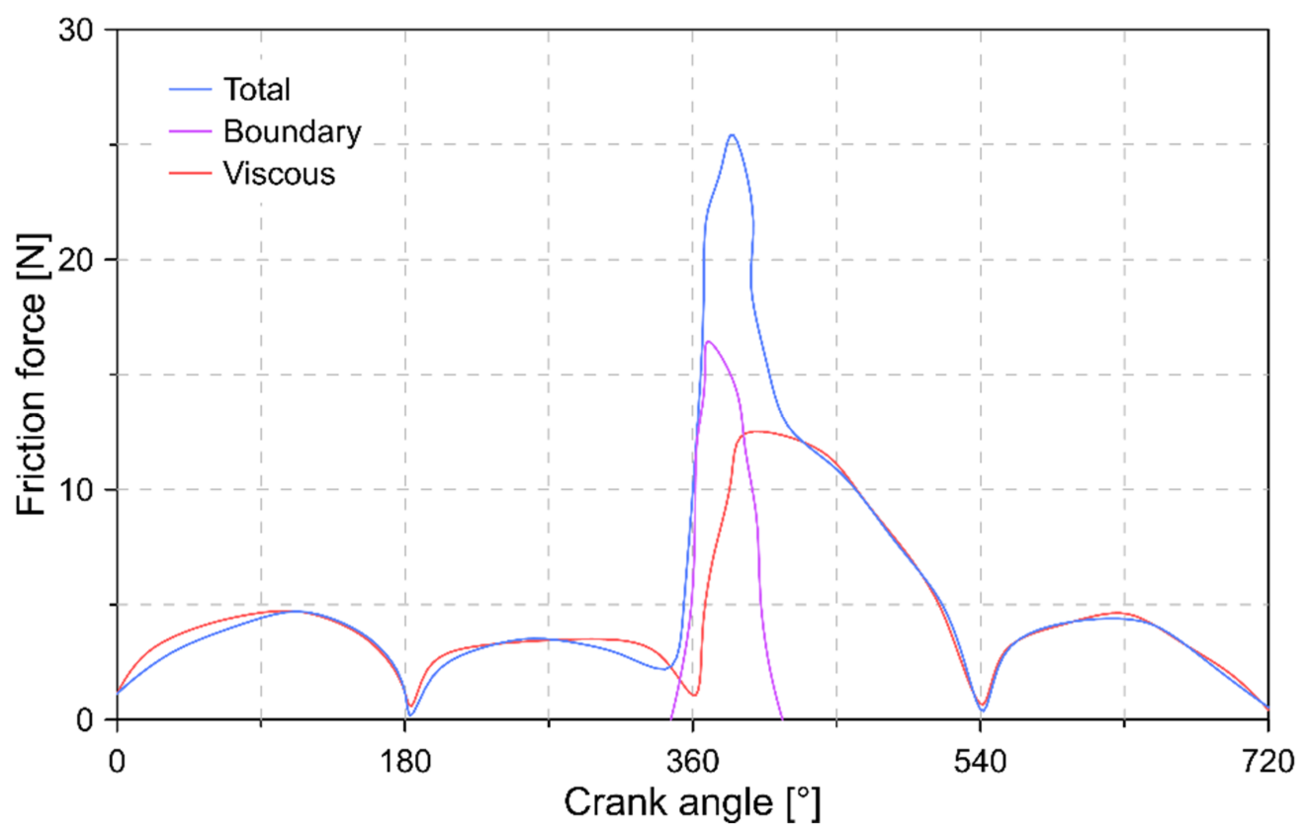
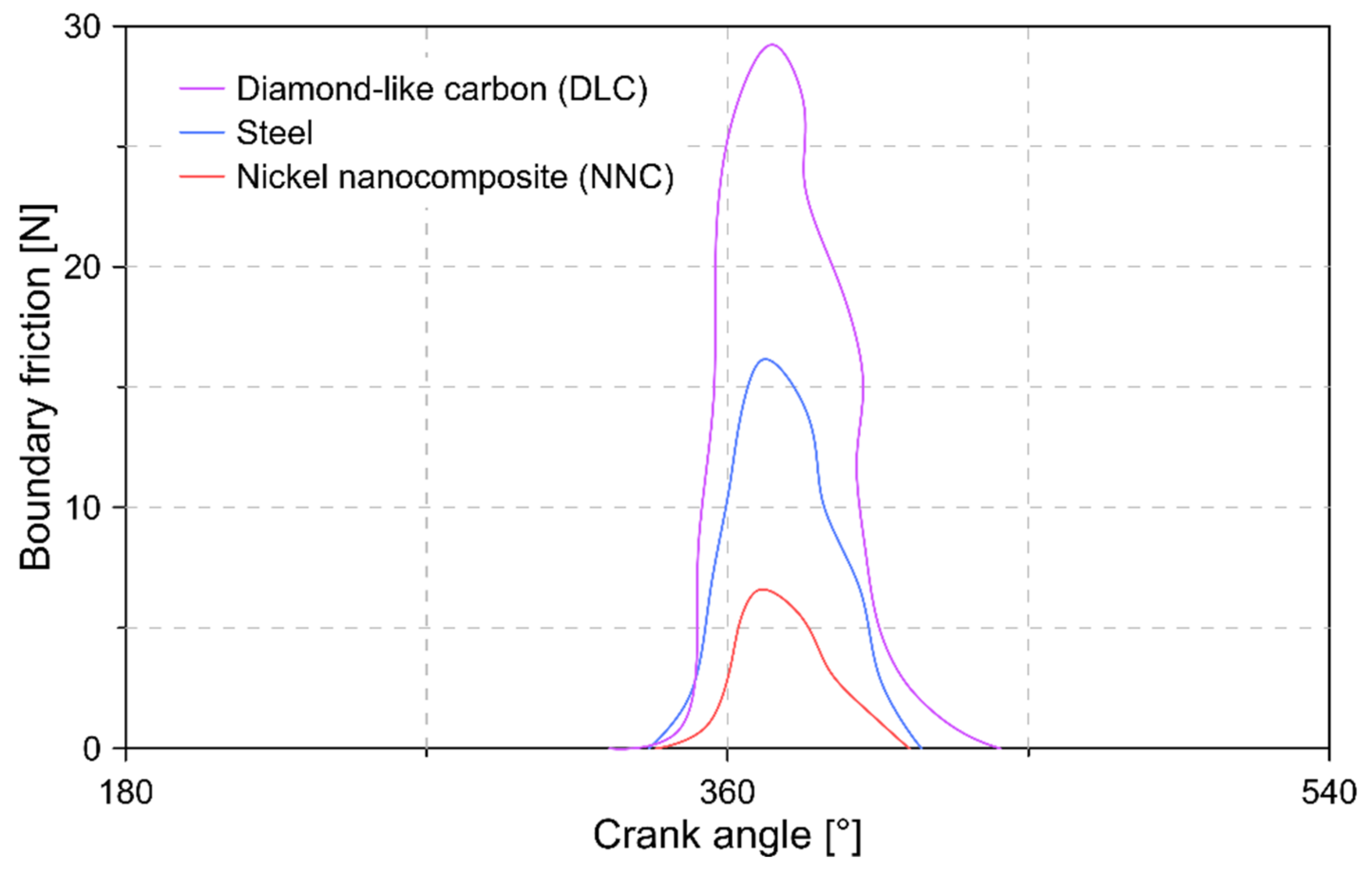
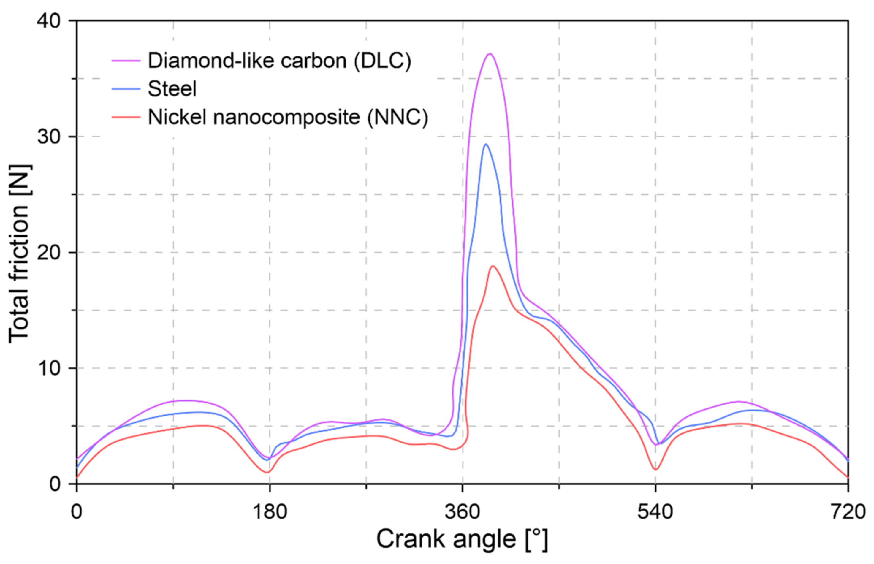
4.2. Friction Force Analysis

Figure 8 shows the behavior of the friction force during the combustion cycle for an uncoated surface, which is used as a basis to determine the influence of coating materials.
The results of Figure 8 show that the compression ring is mainly subjected to a hydrodynamic regime condition throughout the combustion cycle. The above indicates that viscous shear is the main source of friction during the stages of the combustion process. The force due to the pressure of the gases mainly affects the compression and combustion stage, causing the presence of a boundary friction force. This is attributed to a reduction in the thickness of the lubrication film, which decreases below the average height of the asperity of the contact surfaces.
In Figure 9, the influence of the coating material on the boundary friction force is shown. The DLC coating was observed to produce a considerable rise in friction force during the mixed lubrication regime condition. For the simulated conditions, an increase of 13.10 N was obtained compared to the reference condition (steel). This is mainly attributed to the smooth topography of the material, which produces high adherence. An opposite behavior was observed in the NNC coating, in which a decrease of 9.57 N was obtained in the boundary friction force.
Figure 10 shows the total friction force in the compression ring with DLC and NNC and without steel coatings in the cylinder bore.
The results show that the maximum magnitudes of the total friction force are 18.84, 29.35, and 37.19 N for the NNC, steel, and DLC materials, respectively. This maximum force in all conditions is located during the combustion stage, which is a consequence of the pressure generated by the combustion gases on the inner surface of the compression ring.
The change in material in the cylinder bore has a significant effect on the friction process. It was observed that when using the DLC carbon coating, there was a 27% increase in the maximum friction force compared to the cylinder bore without coating (Steel). In the case of the NNC coating, a reduction in the maximum friction force of 36% was observed compared to the cylinder bore without coating. The increase in friction force in the DLC material is attributed to its lower thermal conductivity and the higher coefficient of shear compared to the NNC, as shown in Table 4. The above causes a high adhesion surface when using DLC.

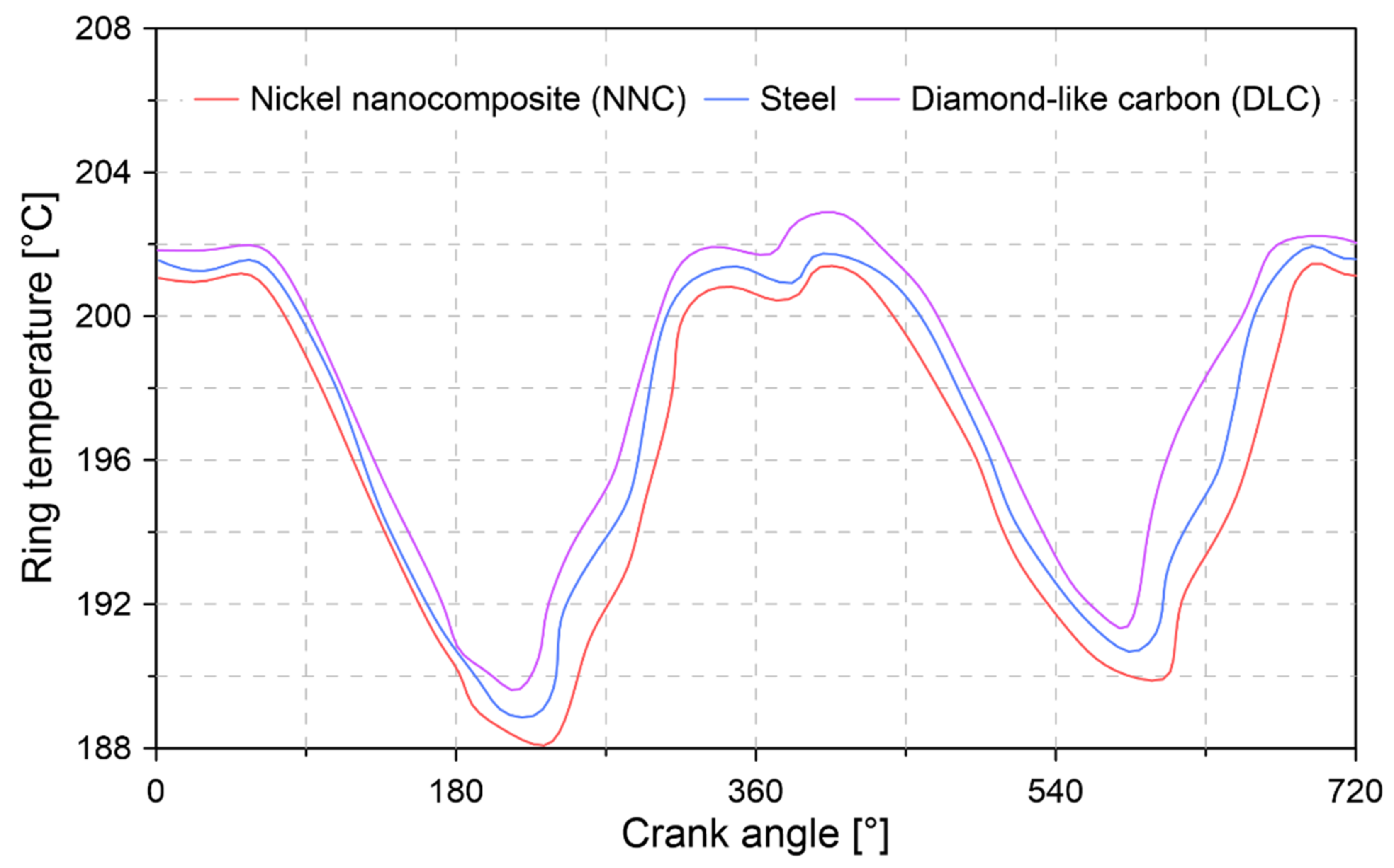
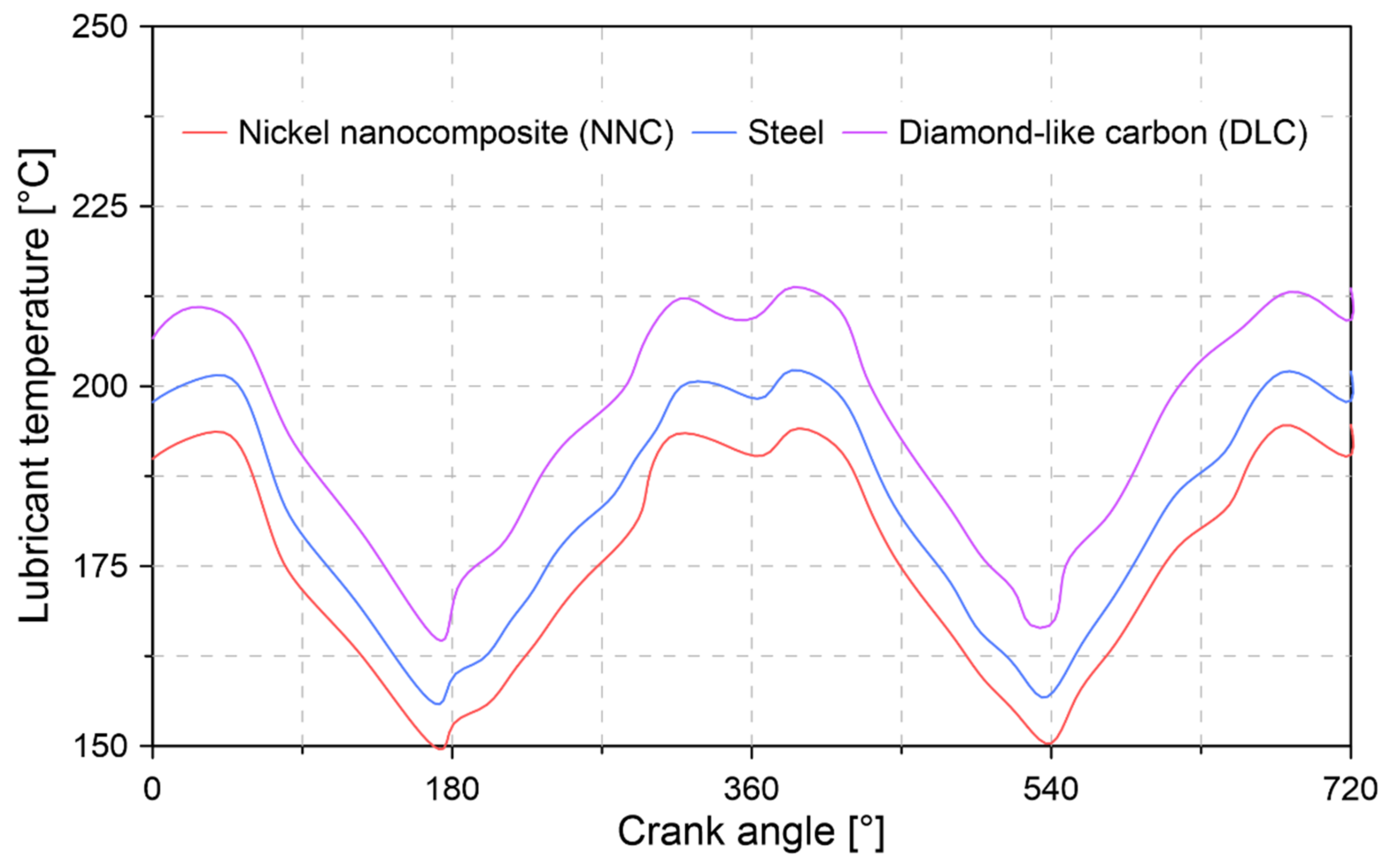
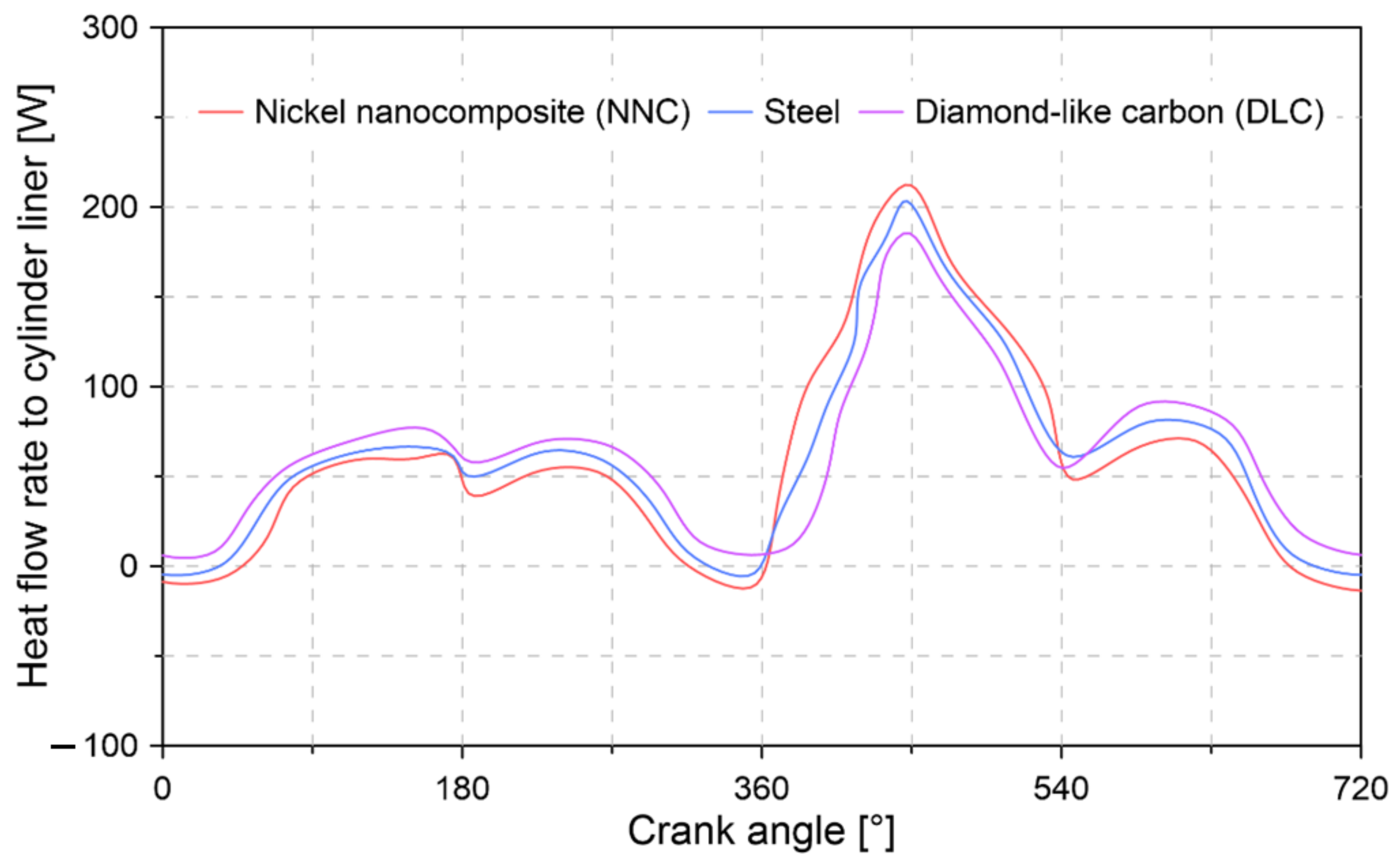
4.3. Temperature and Heat Flow Analysis

Figure 11 shows the temperature behavior of the compression ring for the different surfaces of the cylinder bore.
In Figure 11, it was observed that the change in the material in the cylinder bore caused a change in the temperature of the compression ring, which is a consequence of the different heat transfer coefficients of each material. The results show a reduction of 0.23% and an increase of 0.34% in the temperature of the compression ring when using coatings of NNC and DLC, respectively. This temperature reduction is a consequence of the thermal and tribological properties of the NNC coating.
Figure 12 shows the change in lubricant temperature for the different coatings. The increase in lubricant temperature is mainly due to the conduction heat transfer mechanism. The results show that the coating of NNC and DLC does not cause a considerable change in the temperature of the lubricant compared to steel.
Figure 13 describes the behavior of the heat flow when using the different materials in the cylinder bore.
In the case of the DLC coating, an 8.65% reduction in heat flow transferred through the cylinder liner was observed compared to steel. This behavior is attributed to the lower thermal conductivity of the DLC material, which allows the better insulation of the combustion chamber. The above behavior occurs during the combustion stage. However, it changes during the intake, compression, and exhaust stages because, in these conditions, the formation of heat prevails due to the thickness of the material, which is higher in the DLC coating. For the NNC coating, an inverse behavior to the DLC coating was observed, in which an increase of 4.61% and 14.52% was obtained in the heat flow transferred through the cylinder liner compared to steel and the DLC coating. This implies a greater loss of heat during the compression stage.

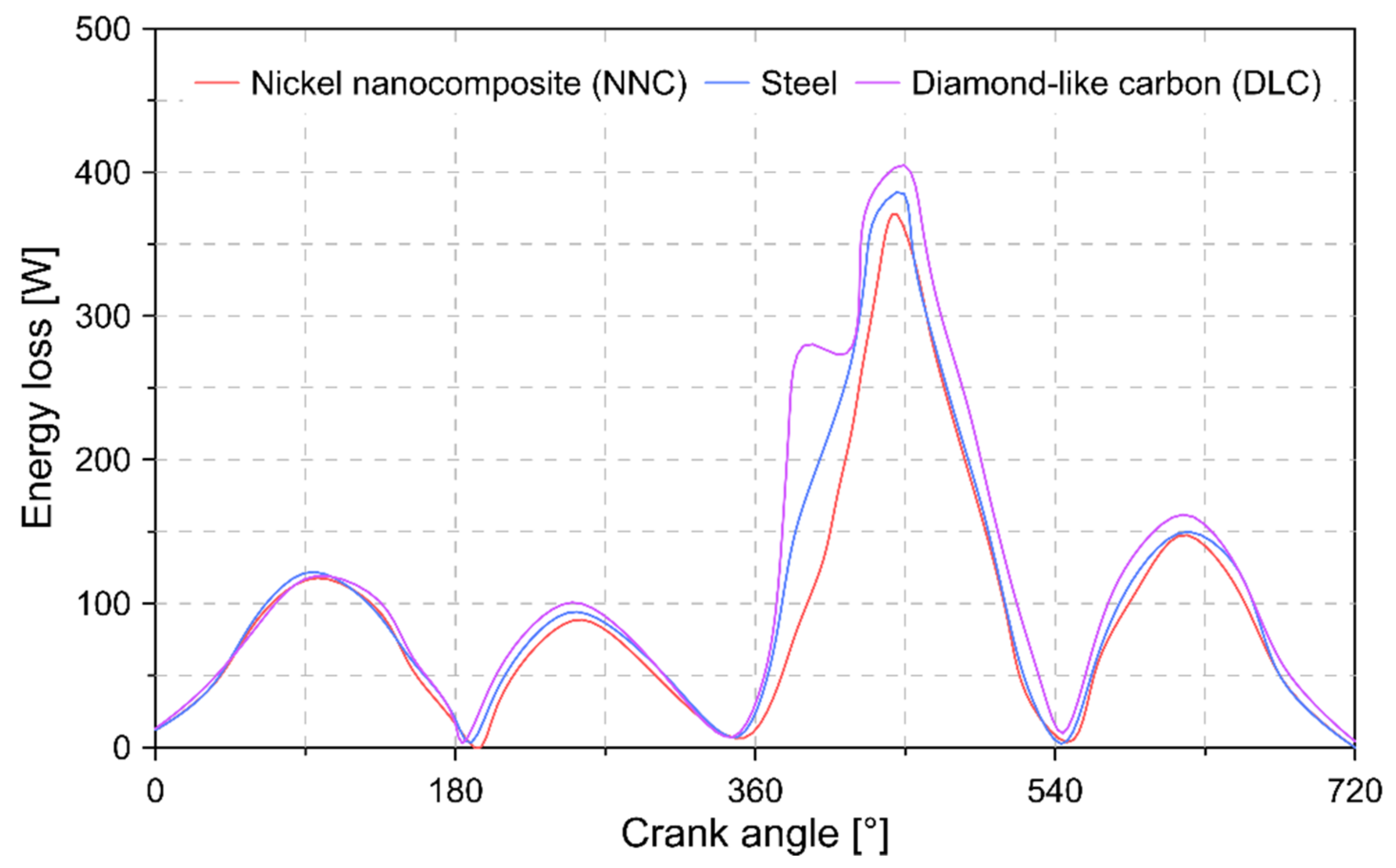
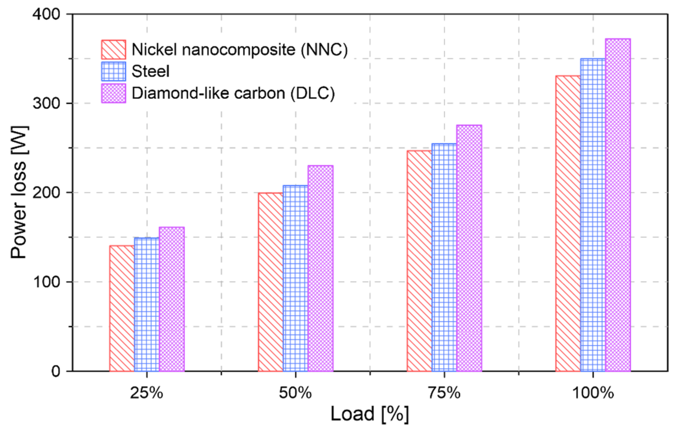
4.4. Power Loss Analysis

Figure 14 shows the behavior of energy loss during the combustion cycle for the different coating materials.
The results show that the highest energy losses occur in the DLC coating, compared to the steel and the NNC coating, respectively. This greater energy loss occurs mainly during the first half of the combustion stage due to the mixed regime condition and the high shear rate of the DLC material. The reduction in energy loss in the NNC material implies better tribological performance.
To analyze the effect of the cylinder bore coating on the mechanical power loss of the engine, the energy loss is evaluated for load conditions of 25%, 50%, 75%, and 100% at a constant rotation speed of 3600 rpm. The results of this analysis are shown in Figure 15.
The results obtained show that the maximum power loss for the NNC and DLC coatings are 330.70 W and 372.26 W, respectively. In the case of the cylinder bore without a coating (steel material), a maximum power loss of 349.96 W was obtained. In general, the NNC coating allows a 4.60% reduction in power loss. This behavior is attributed to the reduction in the total friction force, as shown in Figure 8.

4.5. Fuel Economy

The reduction in engine power loss implies a decrease in fuel consumption and CO emissions. The influence of the NNC and DLC coating on these parameters is shown in Figure 16. For the calculation, the estimate of the global diesel vehicle fleet for the year 2025 is considered, which corresponds to one hundred and eighty million engines [64].
The estimation is performed considering that the technical characteristics of these engines are similar to those of the test engine used in the present study. The calculation of fuel consumption and CO emissions is carried out using the air/fuel ratio and the equivalence ratio, as indicated in Equations (25) and (28). Additionally, through simulation an operating condition is established in the engine for 1800s in order to represent the characteristics of the WLTC test.
Figure 16 depicts the fuel savings and decreased CO emissions obtained by implementing an NNC coating on the cylinder bore. The results show average reductions of 4810 and 26.64 kg in the parameters of fuel consumption and CO emissions, respectively. However, these estimates are limited since only a single cylinder is being considered in the simulation conditions. Therefore, the potential for reducing fuel consumption and CO emissions would be greater when considering the savings in each cylinder.
Figure 17 shows the increase in fuel and CO emissions caused by the DLC coating due to the increase in power loss. Overconsumption of fuel and CO emissions of 8130 and 31.92 kg, respectively, were observed.

5. Summary

In the present study, a numerical model is carried out to evaluate the influence of the material used as a coating on a cylinder bore. The implemented model considers the tribological behavior, heat flows, and leakage of the combustion gases in the chamber. For the analysis, DLC and NNC materials are considered as alternatives for coating the cylinder bore.
The study shows that variations in coating properties cause a significant change in the friction force to which the compression ring is subjected. In general, the NNC coating produces a 32% reduction in the total frictional force of the compression ring throughout the combustion cycle. An opposite case occurs with the DLC coating, in which there is a 33% increase in the friction force. This behavior is a direct consequence of the higher shear coefficient of the DLC material.
The characteristics of the DLC material allow the greater thermal insulation of the combustion chamber, which reduces the associated losses due to heat transfer during the combustion stage. However, this insulation causes an increase in the temperature of the lubricant. For the tested conditions, maximum temperatures of 214, 202, and 194 °C were obtained in the lubrication oil for the DLC, steel (uncoated), and NNC materials. Increasing the temperature when using the DLC coating can cause a reduction in the tribological performance of the lubricant. In general, NNC and DLC coatings cause a reduction and an increase of 3.68% and 5.71% in the lubrication oil temperature.
The research shows that the application of an NNC coating on the cylinder bore allows a reduction of 4.60% of the power lost by the friction process between the compression ring and the cylinder liner compared to the case without coating. The properties of the DLC coating produce an increase in a power loss of 8.38%.
The reduction in power loss implies a decrease in fuel consumption and polluting emissions, such as carbon monoxide. The estimates made show a maximum reduction of 5280 kg of fuel and 39.30 kg of CO emissions when considering the diesel engine fleet for the year 2025. In the case of the DLC coating, the greater power loss causes a maximum increase of 8950 kg of fuel and 39.77 kg of CO emissions.
The proposed numerical model allows future analyses to be carried out for other types of materials used as coatings. Additionally, the model can be expanded and adapted to consider other systems that involve friction processes, such as valve and bearing systems in ICEs.

Author Contributions

Conceptualization, S.O.A. and C.P.G.; Methodology, C.P.G. and J.P.L.; Software, C.P.G.; Validation, S.O.A.; Formal analysis, C.P.G.; Investigation, S.O.A.; Resources, S.O.A., Writing—Original Draft Preparation, S.O.A.; Writing—Review & Editing, C.P.G. and J.P.L.; Funding acquisition, C.P.G. All authors have read and agreed to the published version of the manuscript.

Funding

This research received no external funding.

Institutional Review Board Statement

Not applicable.

Informed Consent Statement

Not applicable.

Data Availability Statement

Not available.

Acknowledgments

The authors would like to acknowledge the Universidad Francisco de Paula Santander and Sphere Energy company for their support in the development of this investigation.

Conflicts of Interest

The authors declare no conflict of interest.

Abbreviations

The following abbreviations are used in this manuscript:
Nomenclature
NNCNickel nanocomposite
DLCDiamond-like carbon
COCarbon monoxide
ICEInternal combustion engine
v p Piston velocity
a p Piston acceleration
l Longitude
d Horizontal distance between the axis of movement of the piston and the crankshaft
PPressure
TTemperature
c p Model constant
SThermo-viscosity indices
ZLubricant piezo-viscosity
η Model constant
h Lubrication film thickness
FForce
mMass
P c Asperity contact pressure
c f Pressure coefficient of boundary shear
E Young’s modulus
F 5 / 2 Commutation function
H s Film thickness ratio
ϑ Poisson ratio
P u p s Upstream pressure wave
RGas constant
c d Coefficient of discharge
A v Valve area
γ Specific heat ratio
D v Diameter of the valve
Q ˙ Heat flow
RThermal resistance
h c Convection coefficient
S f Equivalent length
Q L H V Lower calorific value
m ˙ Mass flow
A F Air/fuel ratio
Greek Letters
θ Angle of rotation of the crankshaft
ω Angular velocity
ψ Angle formed between the axis of movement of the connecting rod and the piston
ρ Density
β Coefficient of thermal expansion
η Viscosity
σ Surface roughness
ϕ Equivalence relation
Subscripts
c r Crankshaft
r o d Connecting rod
o Environmental conditions
h y d r o Hydrodinamic
f r i c Friction
rCompression ring
a s p Asperities
c Cylinder liner
ccCombustion chamber
l u b Lubricating oil
t Total
s Contact surfaces
csCoated surfaces
c r Cylinder bore
rrReal
ssStoichiometric
f Fuel

References

  1. Forero, J.D.; Taborda, L.L.; Silvera, A.B. Characterization of the Performance of Centrifugal Pumps Powered by a Diesel Engine in Dredging Applications. Int. Rev. Mech. Eng. (IREME) 2019, 13, 11. [Google Scholar] [CrossRef]
  2. Orozco, T.; Herrera, M.; Forero, J.D. CFD Study of Heat Exchangers Applied in Brayton Cycles: A Case Study in Supercritical Condition Using Carbon Dioxide as Working Fluid. Int. Rev. Model. Simulations (IREMOS) 2019, 12, 72–81. [Google Scholar] [CrossRef]
  3. Obregon, L.; Valencia, G.; Forero, J.D. Efficiency Optimization Study of a Centrifugal Pump for Industrial Dredging Applications Using CFD. Int. Rev. Model. Simulations (IREMOS) 2019, 12, 245. [Google Scholar] [CrossRef]
  4. Ochoa, G.V.; Peñaloza, C.A.; Forero, J.D. Thermo-Economic Assessment of a Gas Microturbine-Absorption Chiller Trigeneration System under Different Compressor Inlet Air Temperatures. Energies 2019, 12, 4643. [Google Scholar] [CrossRef] [Green Version]
  5. Ochoa, G.V.; Isaza-Roldan, C.; Forero, J.D. Economic and Exergo-Advance Analysis of a Waste Heat Recovery System Based on Regenerative Organic Rankine Cycle under Organic Fluids with Low Global Warming Potential. Energies 2020, 13, 1317. [Google Scholar] [CrossRef] [Green Version]
  6. Amador, G.; Forero, J.D.; Rincon, A.; Fontalvo, A.; Bula, A.; Padilla, R.V.; Orozco, W. Characteristics of Auto-Ignition in Internal Combustion Engines Operated With Gaseous Fuels of Variable Methane Number. J. Energy Resour. Technol. 2017, 139, 042205. [Google Scholar] [CrossRef]
  7. Duarte, J.; Garcia, J.; Jiménez, J.; Sanjuan, M.E.; Bula, A.; González, J. Auto-Ignition Control in Spark-Ignition Engines Using Internal Model Control Structure. J. Energy Resour. Technol. 2017, 139, 022201. [Google Scholar] [CrossRef]
  8. Orozco, W.; Acuña, N.; Forero, J.D. Characterization of Emissions in Low Displacement Diesel Engines Using Biodiesel and Energy Recovery System. Int. Rev. Mech. Eng. (IREME) 2017, 13, 420. [Google Scholar] [CrossRef]
  9. Rahnejat, H. Tribology and Dynamics of Engine and Powertrain: Fundamentals, Applications and Future Trends; Woodhead Publishing: Cambridge, UK, 2010. [Google Scholar] [CrossRef]
  10. Richardson, D.E. Review of Power Cylinder Friction for Diesel Engines. J. Eng. Gas Turbines Power 2000, 122, 506–519. [Google Scholar] [CrossRef]
  11. Ochoa, G.V.; Gutierrez, J.C.; Forero, J.D. Exergy, Economic, and Life-Cycle Assessment of ORC System for Waste Heat Recovery in a Natural Gas Internal Combustion Engine. Resources 2020, 9, 2. [Google Scholar] [CrossRef] [Green Version]
  12. Holmberg, K.; Erdemir, A. Influence of tribology on global energy consumption, costs and emissions. Friction 2017, 5, 263–284. [Google Scholar] [CrossRef]
  13. Holmberg, K.; Andersson, P.; Nylund, N.-O.; Mäkelä, K.; Erdemir, A. Global energy consumption due to friction in trucks and buses. Tribol. Int. 2014, 78, 94–114. [Google Scholar] [CrossRef]
  14. Holmberg, K.; Andersson, P.; Erdemir, A. Global energy consumption due to friction in passenger cars. Tribol. Int. 2012, 47, 221–234. [Google Scholar] [CrossRef]
  15. Ma, M.-T.; Sherrington, I.; Smith, E.H. Analysis of lubrication and friction for a complete piston-ring pack with an improved oil availability model: Part 1: Circumferentially uniform film. Proc. Inst. Mech. Eng. Part J J. Eng. Tribol. 1997, 211, 1–15. [Google Scholar] [CrossRef]
  16. Ma, Z.; Henein, N.A.; Bryzik, W. A Model for Wear and Friction in Cylinder Liners and Piston Rings. Tribol. Trans. 2006, 49, 315–327. [Google Scholar] [CrossRef]
  17. Mishra, P.C.; Balakrishnan, S.; Rahnejat, H. Tribology of compression ring-to-cylinder contact at reversal. Proc. Inst. Mech. Eng. Part J J. Eng. Tribol. 2008, 222, 815–826. [Google Scholar] [CrossRef] [Green Version]
  18. Mishra, P.C. Tribodynamic modeling of piston compression ring and cylinder liner conjunction in high-pressure zone of engine cycle. Int. J. Adv. Manuf. Technol. 2013, 66, 1075–1085. [Google Scholar] [CrossRef]
  19. Rahmani, R.; Theodossiades, S.; Rahnejat, H.; Fitzsimons, B. Transient elastohydrodynamic lubrication of rough new or worn piston compression ring conjunction with an out-of-round cylinder bore. Proc. Inst. Mech. Eng. Part J J. Eng. Tribol. 2012, 226, 284–305. [Google Scholar] [CrossRef] [Green Version]
  20. Baker, C.; Theodossiades, S.; Rahmani, R.; Rahnejat, H.; Fitzsimons, B. On the Transient Three-Dimensional Tribodynamics of Internal Combustion Engine Top Compression Ring. J. Eng. Gas Turbines Power 2017, 139, 062801. [Google Scholar] [CrossRef]
  21. Morris, N.; Rahmani, R.; Rahnejat, H.; King, P.D.; Fitzsimons, B. Tribology of piston compression ring conjunction under transient thermal mixed regime of lubrication. Tribol. Int. 2013, 59, 248–258. [Google Scholar] [CrossRef] [Green Version]
  22. Rahmani, R.; Rahnejat, H.; Fitzsimons, B.; Dowson, D. The effect of cylinder liner operating temperature on frictional loss and engine emissions in piston ring conjunction. Appl. Energy 2017, 191, 568–581. [Google Scholar] [CrossRef] [Green Version]
  23. Morris, N.; Mohammadpour, M.; Rahmani, R.; Johns-Rahnejat, P.M.; Rahnejat, H.; Dowson, D. Effect of cylinder deactivation on tribological performance of piston compression ring and connecting rod bearing. Tribol. Int. 2018, 120, 243–254. [Google Scholar] [CrossRef]
  24. Saidur, R.; Rezaei, M.; Muzammil, W.K.; Hassan, M.H.; Paria, S.; Hasanuzzaman, M. Technologies to recover exhaust heat from internal combustion engines. Renew. Sustain. Energy Rev. 2012, 16, 5649–5659. [Google Scholar] [CrossRef]
  25. Liu, Z.; Meng, X.; Wen, C.; Yu, S.; Zhou, Z. On the oil-gas-solid mixed bearing between compression ring and cylinder liner under starved lubrication and high boundary pressures. Tribol. Int. 2019, 140, 105869. [Google Scholar] [CrossRef]
  26. Roensch, M.M. Piston-Ring Coatings and Their Effect on Ring and Bore Wear. SAE Trans. 1940, 221–228. [Google Scholar] [CrossRef]
  27. Howell-Smith, S.; Rahnejat, H.; King, P.D.; Dowson, D. Reducing in-cylinder parasitic losses through surface modification and coating. Proc. Inst. Mech. Eng. Part D J. Automob. Eng. 2014, 228, 391–402. [Google Scholar] [CrossRef] [Green Version]
  28. Dahotre, N.B.; Nayak, S. Nanocoatings for engine application. Surf. Coatings Technol. 2005, 194, 58–67. [Google Scholar] [CrossRef]
  29. Rejowski, E.D.; Mordente, P., Sr.; Pillis, M.F.; Casserly, T. Application of DLC Coating in Cylinder Liners for Friction Reduction; Technical Paper; SAE: Warrendale, PA, USA, 2012. [Google Scholar]
  30. Yuan, C.; Ren, H.; Xu, J. Experiment on the ignition performances of a free-piston diesel engine alternator. Appl. Therm. Eng. 2018, 134, 537–545. [Google Scholar] [CrossRef]
  31. Kim, D.; Ito, A.; Ishikawa, Y.; Osawa, K.; Iwasaki, Y. Friction Characteristics of Steel Pistons for Diesel Engines. J. Mater. Res. Technol. 2012, 1, 96–102. [Google Scholar] [CrossRef] [Green Version]
  32. Tan, Y.-C.; Ripin, Z.M. Technique to determine instantaneous piston skirt friction during piston slap. Tribol. Int. 2014, 74, 145–153. [Google Scholar] [CrossRef]
  33. Moffat, A.; Barnes, S.; Mellor, B.; Reed, P. The effect of silicon content on long crack fatigue behaviour of aluminium–silicon piston alloys at elevated temperature. Int. J. Fatigue 2005, 27, 1564–1570. [Google Scholar] [CrossRef]
  34. Yao, Z.-M.; Qian, Z.-Q.; Li, R.; Hu, E. Energy efficiency analysis of marine high-powered medium-speed diesel engine base on energy balance and exergy. Energy 2019, 176, 991–1006. [Google Scholar] [CrossRef]
  35. Mahato, A.; Xia, S.; Perry, T.; Sachdev, A.; Biswas, S.K. Role of silicon in resisting subsurface plastic deformation in tribology of aluminium–silicon alloys. Tribol. Int. 2010, 43, 381–387. [Google Scholar] [CrossRef]
  36. Vural, E. The Study of Microstructure and Mechanical Properties of Diesel Engine Piston Coated with Carbide Composites by Using HVOF Method. Trans. Indian Inst. Met. 2020, 73, 2613–2622. [Google Scholar] [CrossRef]
  37. Vadivel, A.; Periyasamy, S. Experimental Investigation of Thermal Barrier (8YSZ-MGO-TIO2) Coated Piston used in Diesel Engine. J. Appl. Fluid Mech. 2020, 13, 1157–1165. [Google Scholar] [CrossRef]
  38. Yang, W.; Li, X.-R.; Zhao, W.-H.; Kang, Y.-N.; Liu, F.-S. Effect of Layered-Port VVT on Performance of Opposed-Piston Two-Stroke Diesel Engine. J. Energy Eng. 2019, 145, 04019027. [Google Scholar] [CrossRef]
  39. Yao, Z.; Hu, K.; Li, R. Enhanced high-temperature thermal fatigue property of aluminum alloy piston with Nano PYSZ thermal barrier coatings. J. Alloys Compd. 2019, 790, 466–479. [Google Scholar] [CrossRef]
  40. Nguyen, C.L.; Preston, A.; Tran, A.T.; Dickinson, M.; Metson, J.B. Adhesion enhancement of titanium nitride coating on aluminum casting alloy by intrinsic microstructures. Appl. Surf. Sci. 2016, 377, 174–179. [Google Scholar] [CrossRef]
  41. Chen, W.-C.; Lin, H.-M.; Uan, J.-Y. Formation and characterization of self-lubricated carbide layer on AA6082 Al–Mg–Si aluminum alloy by electrical discharge alloying process. Trans. Nonferrous Met. Soc. China 2016, 26, 3205–3218. [Google Scholar] [CrossRef]
  42. Chi, Y.; Gu, G.; Yu, H.; Chen, C. Laser surface alloying on aluminum and its alloys: A review. Opt. Lasers Eng. 2018, 100, 23–37. [Google Scholar] [CrossRef]
  43. Perera, M.S.M.; Theodossiades, S.; Rahnejat, H. Elasto-multi-body dynamics of internal combustion engines with tribological conjunctions. Proc. Inst. Mech. Eng. Part K J. Multi Body Dyn. 2010, 224, 261–277. [Google Scholar] [CrossRef] [Green Version]
  44. Consuegra, F.; Bula, A.; Guillín, W.; Sánchez, J.; Forero, J.D. Instantaneous in-Cylinder Volume Considering Deformation and Clearance due to Lubricating Film in Reciprocating Internal Combustion Engines. Energies 2019, 12, 1437. [Google Scholar] [CrossRef] [Green Version]
  45. Lyubarskyy, P.; Bartel, D. 2D CFD-model of the piston assembly in a diesel engine for the analysis of piston ring dynamics, mass transport and friction. Tribol. Int. 2016, 104, 352–368. [Google Scholar] [CrossRef]
  46. Cui, J.; Yang, P.; Jin, Z.M.; Dowson, D. Transient elastohydrodynamic analysis of elliptical contacts. Part 3: Non-Newtonian lubricant solution under isothermal and thermal conditions. Proc. Inst. Mech. Eng. Part J J. Eng. Tribol. 2007, 221, 63–73. [Google Scholar] [CrossRef]
  47. Houpert, L. New Results of Traction Force Calculations in Elastohydrodynamic Contacts. J. Tribol. 1985, 107, 241–245. [Google Scholar] [CrossRef]
  48. Delprete, C.; Razavykia, A.; Baldissera, P. Detailed analysis of piston secondary motion and tribological performance. Int. J. Engine Res. 2020, 21, 1647–1661. [Google Scholar] [CrossRef]
  49. Sonthalia, A.; Kumar, R.R. The effect of compression ring profile on the friction force in an internal combustion engine. Tribol. Ind. 2013, 35, 74–83. [Google Scholar]
  50. Ali, M.K.A.; Xianjun, H.; Turkson, R.F.; Ezzat, M. An analytical study of tribological parameters between piston ring and cylinder liner in internal combustion engines. Proc. Inst. Mech. Eng. Part K J. Multi Body Dyn. 2016, 230, 329–349. [Google Scholar] [CrossRef]
  51. Husain, S.Q.; Singh, K.P. Calculation of Lubricating Oil Film Thickness between Piston Rings and Cylinder Liner. In Proceedings of the 1st National Conference on Advances in Mechanical Engineering (NCAME 2011), Chandigarh, India, 20–21 May 2011. [Google Scholar]
  52. Zavos, A.B.; Nikolakopoulos, P.G. Simulation of piston ring tribology with surface texturing for internal combustion engines. Lubr. Sci. 2015, 27, 151–176. [Google Scholar] [CrossRef]
  53. Balakrishnan, S.; Rahnejat, H. Isothermal transient analysis of piston skirt-to-cylinder wall contacts under combined axial, lateral and tilting motion. J. Phys. D Appl. Phys. 2005, 38, 787–799. [Google Scholar] [CrossRef]
  54. Booker, J.F. Basic Equations for Fluid Films with Variable Properties. J. Tribol. 1989, 111, 475–479. [Google Scholar] [CrossRef]
  55. Irimescu, A.; Di Iorio, S.; Merola, S.S.; Sementa, P.; Vaglieco, B.M. Evaluation of compression ratio and blow-by rates for spark ignition engines based on in-cylinder pressure trace analysis. Energy Convers. Manag. 2018, 162, 98–108. [Google Scholar] [CrossRef]
  56. Zucrow, M.J.; Hoffman, J.D. Gas Dynamics. In Fundamental Fluid Mechanics for the Practicing Engineer; CRC Press: Boca Raton, FL, USA, 2018; pp. 198–297. [Google Scholar]
  57. Dieck, R.H. Measurement Uncertainty: Methods and Applications, 4th ed.; ISA: Durham, NC, USA, 2007. [Google Scholar]
  58. Umer, J.; Morris, N.J.; Leighton, M.; Rahmani, R.; Howell-Smith, S.; Wild, R.; Rahnejat, H. Asperity level tribological investigation of automotive bore material and coatings. Tribol. Int. 2018, 117, 131–140. [Google Scholar] [CrossRef] [Green Version]
  59. Tomanik, E.; Profito, F.J.; Zachariadis, D.C. Modelling the hydrodynamic support of cylinder bore and piston rings with laser textured surfaces. Tribol. Int. 2013, 59, 90–96. [Google Scholar] [CrossRef]
  60. Humphrey, E.; Morris, N.J.; Rahmani, R.; Rahnejat, H. Multiscale boundary frictional performance of diamond like carbon coatings. Tribol. Int. 2020, 149, 105539. [Google Scholar] [CrossRef]
  61. Zavos, A.; Nikolakopoulos, P.G. Tribology of new thin compression ring of fired engine under controlled conditions—A combined experimental and numerical study. Tribol. Int. 2018, 128, 214–230. [Google Scholar] [CrossRef]
  62. Koch, F.; Decker, P.; Gülpen, R.; Quadflieg, F.-J.; Loeprecht, M. Cylinder Liner Deformation Analysis—Measurements and Calculations; Technical Paper; SAE: Warrendale, PA, USA, 1998. [Google Scholar] [CrossRef]
  63. Gore, M.; Theaker, M.; Howell-Smith, S.; Rahnejat, H.; King, P.D. Direct measurement of piston friction of internal-combustion engines using the floating-liner principle. Proc. Inst. Mech. Eng. Part D J. Automob. Eng. 2014, 228, 344–354. [Google Scholar] [CrossRef] [Green Version]
  64. ExxonMobil. The Outlook for Energy: A View to 2040 Contents. 2017. Available online: http://oilproduction.net/files/2017_Outlook_for_Energy_highlights.pdf (accessed on 12 December 2020).
Figure 1. Movement of the crankshaft—connecting rod—piston mechanism.
Lubricants 09 00019 g001
Figure 2. Compression ring thermal model.
Lubricants 09 00019 g002
Figure 3. Experimental test bench used in experimentation. 1. Fuel tank. 2. Fuel control valve. 3. Air flow indicator. 4. Thermocouple. 5. Dynamometer controller. 6. Dynamometer. 7. Engine diesel. 8. In-cylinder pressure transductor. 9. Charge amplifier. 10. Combustion data acquisition system. 11. Computer. 12. Crank angle encoder.
Lubricants 09 00019 g003
Figure 4. (a) Combustion pressure and (b) piston velocity.
Lubricants 09 00019 g004
Figure 5. Methodological procedure for coating analysis.
Lubricants 09 00019 g005
Figure 6. Measurement of the friction force signal.
Lubricants 09 00019 g006
Figure 7. Comparison between the friction force obtained experimentally vs. numerical model.
Lubricants 09 00019 g007
Figure 8. Friction force variation without coating material (steel).
Lubricants 09 00019 g008
Figure 9. Boundary friction force for different coating materials.
Lubricants 09 00019 g009
Figure 10. Effect of cylinder bore coating on the total friction force.
Lubricants 09 00019 g010
Figure 11. Effect of the cylinder bore coating on the compression ring temperature.
Lubricants 09 00019 g011
Figure 12. Effect of the cylinder bore coating on lubricant temperature.
Lubricants 09 00019 g012
Figure 13. Effect of cylinder liner coating on heat flow.
Lubricants 09 00019 g013
Figure 14. Behavior of energy loss during a combustion cycle.
Lubricants 09 00019 g014
Figure 15. Loss of power for different load conditions on the engine.
Lubricants 09 00019 g015
Figure 16. Variation in the fuel consumption and CO emissions for the coating Nickel nanocomposite (NNC).
Lubricants 09 00019 g016
Figure 17. Variation in fuel consumption and CO emissions for coating diamond-like carbon (DLC).
Lubricants 09 00019 g017
Table 1. Lubrication oil properties.
Properties
Upper explosion limit6.5 vol%
Lower explosion limit0.6 vol%
Viscosity at 40 °C91.76 mm2/s
Flashpoint224 °C (DIN ISO 2592)
Density at 20 °C0.864 g/cm3 (DIN 51757)
Pourpoint−33 °C (ISO 3016)
Table 2. Technical characteristics of the test engine.
ModelSK-MDF300
ManufacturerSOKAN
Cycle4 Strokes
Bore x stroke78 mm
Stroke62.57 mm
Engine type1 cylinder
Maximum power3.43 kW
Compression ratio20:1
Injection systemDirect injection
Intake systemNaturally Aspirated
Displaced volume299 CC
Crankshaft radius 48 mm
Piston radius 39 mm
Length of connecting rod106 mm
Table 3. Technical characteristics and uncertainty of measuring instruments.
InstrumentParameterManufacturerRange U r , x i U s y s , x i U t
Air mass sensorAirflowBOSCH OE-22680 7J6000–125 g/s±1.10±1.02±1.5
Piezoelectric transducerCylinder pressureKISTLER type 7063-A0–250 bar±0.38±0.32±0.5
Gravimetric meterFuel measuringOHAUS—PA3130–310 g±1.06±0.91±1.4
Crankshaft Position SensorsAngleBeck Arnley 180-04205–9999 RPM±0.73±0.68±1.0
Temperature sensorTemperatureType K−200–1370 °C±0.52±0.46±0.7
Table 4. Thermo-mechanical properties of coatings [58,59,60].
ParameterUnitCylinder Bore Surface
Steel 4340NNCDLC
Densitykg/m3785051753510
Thermal conductivityW/mK34.342.14.5
Poisson’s ratio-0.310.310.22
Specific heat capacityJ/kgK5205661300
Young’s modulus of elasticityGPa200165210
Pressure coefficient of boundary shear-0.1700.1490.219
Table 5. Thermo-mechanical properties of the compression ring coating [58].
ParameterUnitTiN
Densitykg/m35220
Thermal conductivityW/mK19.2
Poisson’s ratio-0.25
Specific heat capacityJ/kgK484.9
Young’s modulus of elasticityGPa251
Table 6. Characteristics of the strain gauge sensor.
ParameterValue
Overall width4.55 mm
Gauge resistance120 Ω
Maximum operating temperature1150 °C
Grid width4.55 mm
Overall length6.30 mm
Gage length2.54 mm
Publisher’s Note: MDPI stays neutral with regard to jurisdictional claims in published maps and institutional affiliations.

