Planar Contact Fretting Test Method Applied to Solid Lubricants


1
Institute of Production Technologies, Faculty of Materials Science and Technology, Slovak University of Technology, J. Bottu 23, 917-24 Trnava, Slovakia
2
Hochschule Mannheim—Kompetenzzentrum Tribologie, Paul-Wittsack-Straße 10, 68163 Mannheim, Germany
3
Materiales GmbH, Offakamp 9f, 22529 Hamburg, Germany
4
Faculty of Materials Science and Technology, Slovak University of Technology in Bratislava, Paulínska 16, 917-24 Trnava, Slovakia
*
Authors to whom correspondence should be addressed.
Lubricants 2021, 9(6), 58; https://0-doi-org.brum.beds.ac.uk/10.3390/lubricants9060058
Submission received: 8 March 2021
/
Revised: 14 May 2021
/
Accepted: 17 May 2021
/
Published: 21 May 2021
Abstract
:A new method of material and lubricant testing is demonstrated with a planar contact fretting wear tribometer under typical fretting wear conditions. The usual abstraction of contact geometries with an easy-to-align point or line contacts is deliberately dispensed to do justice to the frequently flat contacts of machine elements (shaft-hub connection, bearing seats, etc.). For the study, a new method of targeted observation of the contact surfaces during the test is used, which allows a time-lapse animation of the fretting wear progress of solid lubricant mixtures. Thus, the formation of possible transfer film build-up and the type of wear mechanism occurring can be visualized. This technique represents, in conjunction with additional analytical methods such as microscopy and SEM/EDX, a powerful tool to provide a better insight into the mechanisms of solid lubricant action under fretting conditions. To demonstrate the potential of this approach, a time to damage study is performed on commercial and self-prepared pastes from solid lubricants and white oil, where calcium hydroxide is a commonly employed solid lubricant for the avoidance of fretting wear is compared to other materials.
1. Introduction
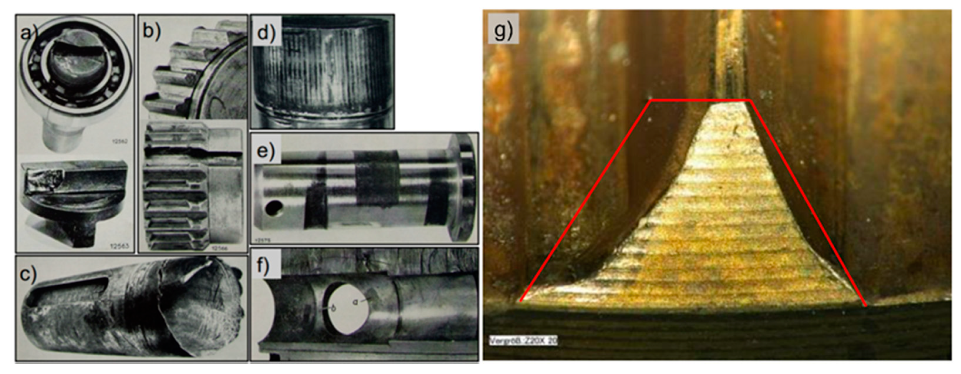
Fretting wear occurs in many technical and everyday applications. Examples of fretting from earlier times [1,2,3] are still of relevance today [4], as shown in Figure 1. In particular, the tooth shaft hub coupling of Figure 1b is a classic example topic of early functional failure or machine breakdown. Fretting wear on the bearing seat on the shaft of Figure 1d can always occur due to shaft bending with inappropriate tolerances and can lead to complete failures, such as the fretting fatigue damage depicted in Figure 1c. The pin shown in Figure 1e is a widely used connection element in consumer products, and the wear on these parts is typical for fretting but mostly uncritical. The only outdated example is the metal Oldham coupling seen in Figure 1a, but it clearly demonstrates how small motion compensation can lead to fretting wear. Figure 1g, on the other hand, presents a modern shaft hub coupling where a change in machine harmonics led to fretting wear problems. The shape of a new tooth is approximately given by the red lines.
Often the collective load would not be described as critical. Low loads, for example, may lead to less friction fit and more displacement. Large contacting surfaces are exposed to self or externally induced vibrations, and fretting conditions can be met if the displacement does not exceed the contact length.
It should be the objective to avoid or mitigate the reason for the vibration or relative motion, but this is often not possible by economical design or use of a machine. Some best practices define the necessary precision of mating parts (e.g., bearing seats) to avoid relative motion; most elements, however, require a clearance to allow a certain freedom of motion or for assembly reasons. Hence, for the avoidance or mitigation of fretting wear as a symptom of small oscillating relative motion in large contacts, there is a need for reasonable treatment.
In this article, we report and focus on the use of a new model test bench, which was developed for the simulation of planar contacts. The usual abstraction of the contact geometries with an easily aligned point or line contacts is deliberately omitted to meet the usually flat contacts in applied tribosystems (shaft-hub connection, bearing seats, mating surfaces, etc.). This also gives lubricants a tiny clearance and volume in between asperities of the mating surfaces. If the lubricant is not able to stay in contact by its properties, the chance to get back into the contact is minimal.
Solid lubricants mixed in oil or in a coating matrix (so-called antifriction coatings) can provide protection against typical fretting wear with symptoms of adhesion and/or metal debris forming [5,6]. Their main function is to provide low, constant and controlled friction by building up a continuous film and be chemically stable under the given conditions. Solid lubricants are known to be a solution of last resort when lubrication is required under extreme conditions. The lubricity of some of the best-known solid lubricants, such as graphite, hexagonal boron nitride (h-BN) or molybdenum disulfide (MoS2), is attributed to their layered lattice structure. Due to weak chemical interactions, the plate-like particles of these materials can align themselves towards a sliding motion and do thus lead to low friction values [7,8].
In contrast, certain other inorganic compounds can provide lubrication under some specific conditions, such as higher temperatures, where they become softer and build up transfer films on the surfaces of friction pairs but do resist oxidation reactions.
As an introduction to the planar contact test method with a new test bench, the article compares and evaluates different mixtures of white oil/solid lubricant each at 50 weight percent (wt.%), see Table 1. Few are known for their performance of avoiding fretting wear. The impact of oscillating motion on the surfaces was monitored by a camera setup, and also the friction forces and surface temperatures were recorded for the whole duration of the test. Observation of the contact surface during the test run is a new key method to examine reaction layers or signs of wear and its mechanisms. After the completion of the experiment, wear patterns and chemical composition of particular surface areas were examined by light microscopy and scanning electron microscopy (SEM).
2. Materials and Methods
The test setup consists of two flat specimens with an ideal contact area of 64 mm2. The test bench has a rigid swivel joint alignment for the specimens to allow a well-distributed plane contact, which plane is also parallel to the axis of motion. Pressure-sensitive foil is used as a visual alignment check. The foil used in the experiment has its maximum intensity color at or above 2 MPa.
Figure 2 shows the test bench, information on the specimen setup and contact alignment procedure. The bench-top apparatus is shown in Figure 2a, and all preparation and handling activities can be performed on the table. The normal force drivetrain extends to below the table-top, where the power and measurement electronics are also placed. The power and measurement electronics are in separate cabinets. A display is placed nearby with a mouse and keyboard to operate the machine. Figure 2b shows the ideal contact area for specimens. The upper and lower specimens are 8 mm wide, 10 mm long and have a thickness of 3 mm. Because the specimens are rotated by 90° on their 10–8 mm surface normal, as shown in Figure 2d, the ideal contact is a square of 8 mm side length. The extra 2 mm length offers space for the motion of the upper specimen and a clamping position tolerance for the lower specimen. If the surface roughness and roughness orientation are critical for an experiment, the specimen orientation must be considered in the setup.
An automated opening of the contact in defined intervals is intended in order to observe the wearing surfaces by acquiring images during a test. The setup uses an industrial camera and a telecentric lens with an image circle fitting the specimen dimensions. The schematic of this procedure is shown in Figure 3.
Opening of the contact is to be considered as relevant in the tribological system analysis [8]. The opening could provide an escape for trapped particles or a new flow of a lubricant to more central contact areas. A different approach is closed contact with a transparent specimen [9], but this limits the abstraction of the tribological system as one element has to be replaced by a transparent body with different properties.
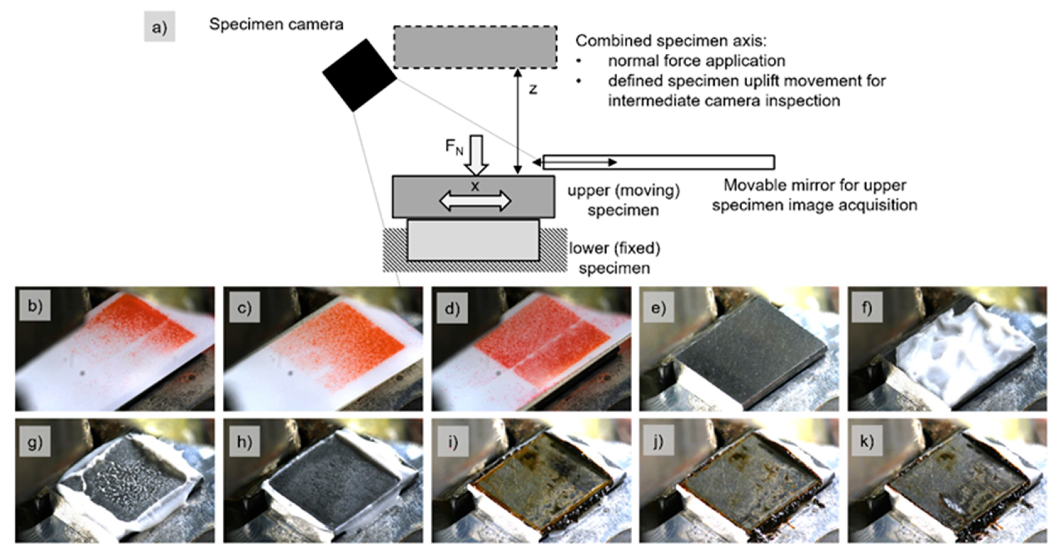
Figure 3a shows the schematic of the opening procedure, where the normal force drive can also unload and move the upper specimen to a defined position, where the upper specimen holder completely clears the sight of an angled camera. The camera is mounted on the orange casing parts shown in Figure 2a. The process is automated via the axis positions and regular checks for plausible normal forces while the contact-opening sequence is being performed. Additionally, a movable mirror as the actual setup on the machine is shown in the schematic of Figure 3a. The mirror can swing in between the specimens while the contact is open to allow the recording of images of the upper specimen. The mirror was added subsequently to the tests performed for this study. The other images of Figure 3 show: (b) to (d) the iterative procedure of contact alignment; (e) the initial condition of the lower specimen; (f) lubrication application and amount; (g) lubrication squeeze out after a single force application; (h)–(k) test images while running until failure.
The drivetrain for the oscillating motion is an adjustable eccentric drive with a servo motor as the main power source and a phase shift mechanism to control the displacement eccentricity. The crankshaft drive is much stiffer than voice coil drive solutions and does not require hydraulic power. A PID-control (proportional, integral, derivative) of the phase shift is sufficient to sustain the desired displacement amplitude.
The displacement measurement system consists of a commercial laser triangulation sensor mounted on a passive mass path near the fixed specimen, the resolution of the device is not better than 0.4 µm and the linearity not better than 0.1% at a sample cycle of 110 µs. The quasi-static normal force measurement is performed via a strain measurement load cell (~2 mV/V, 0.5% linearity) in the force path on the motion axis, which is also used for opening and closing the contact. The axis supplies up to 2 kN of the normal force. The axis control system for the normal force and contact-opening axis are based on “GRBL” open-source software, which uses g-code for axis commands such as CNC machines (computerized numerical control).
The friction measurement is performed on the structural path from the fixed specimen holder to the drivetrain via two piezo-electric strain sensors in a structure symmetric configuration for the cancelation of bending strain charges. This allows only the resulting push/pull strain charge to be amplified by the charge amplifier. The resulting calibration charge per force is quite low, with ~0.5 pC/N, and requires a sophisticated amplifier.
Data acquisition hardware uses the typical 16- to 24-bit analogue interfaces for the measurements. The observation setup uses an industrial camera with a telecentric lens fitted to the specimen dimensions for the object size. The control software is custom programmed in LabVIEW for the test bench measurements and functionalities. The user interface displays every important measure and the control data as well as the live fretting loops and the last acquired images. Additionally, the contact alignment is supported in the software with a special set of positions for the normal force drive.
The acquired data are displayed and saved in different ways. The data from the friction and displacement measurement are usable to show fretting loops [4]. With these hysteresis loops, the contact condition or fretting regime can be distinguished between partial slip and gross slip. Additionally, the mixed slip is possible if low and high friction with a loss of the effective sliding stroke through the elastic deformation occurs over time. Figure 4 shows data acquired from the test bench. Both examples were taken from tests with a 2 kN load. The deformation of the contact as well as the test bench structure (mostly Aluminum structure, around 12.5 µm/kN) is part of the measurement since there is only one displacement sensor. A partial slip with very low strokes can be achieved by motion control and could be a topic of future studies. The coefficient of friction (COF) for time diagram data is also calculated with peak-to-peak values, root mean square (RMS) values or other methods from the raw force loop data. The peak values are used for later interpretation.
Testing Solid Lubricants
An overview of the current test series is shown in Table 1. Most solid lubricants could be mixed 1:1 with medical white oil with a viscosity of 70 mm2/s at 40 °C. The mixture consistency varies with the particle size and surface area; the consideration of such effects would be an important objective for further, more detailed studies with promising solid lubricants. For the use of hexagonal boron nitride and graphite, the amount of solid lubricant was reduced to achieve a paste-like consistency. Since the white oil itself can mitigate fretting for a short period of time, it is expected that results do mainly, but not exclusively, reflect the behavior of the solid lubricants. Additionally, the differences in the miscibility behavior of solid lubricants and white oil must be considered as a limitation of this study.
Studies and data on the fretting wear behavior of solid lubricants in a coating matrix are rather common than in oil-based mixtures [10,11], but these are mostly limited to the investigation of polytetrafluoroethylene (PTFE) or MoS2.
In general, at the boundary or mixed friction regimes, more types of solid lubricants are common [12] and known. For calcium fluoride (CaF2), the behavior on fretting wear seems not to be published, and for calcium hydroxide (Ca(OH)2), only a few but promising results are available [12].
Besides Ca(OH)2, which also finds commercial applications, other metal hydroxides, e.g., Al(OH)3 or NaOH, could behave similarly if a reaction with iron occurs at the metallic surface. According to the literature, they have not been tested on fretting wear avoidance.
3. Results
3.1. Results from Online and Image Data
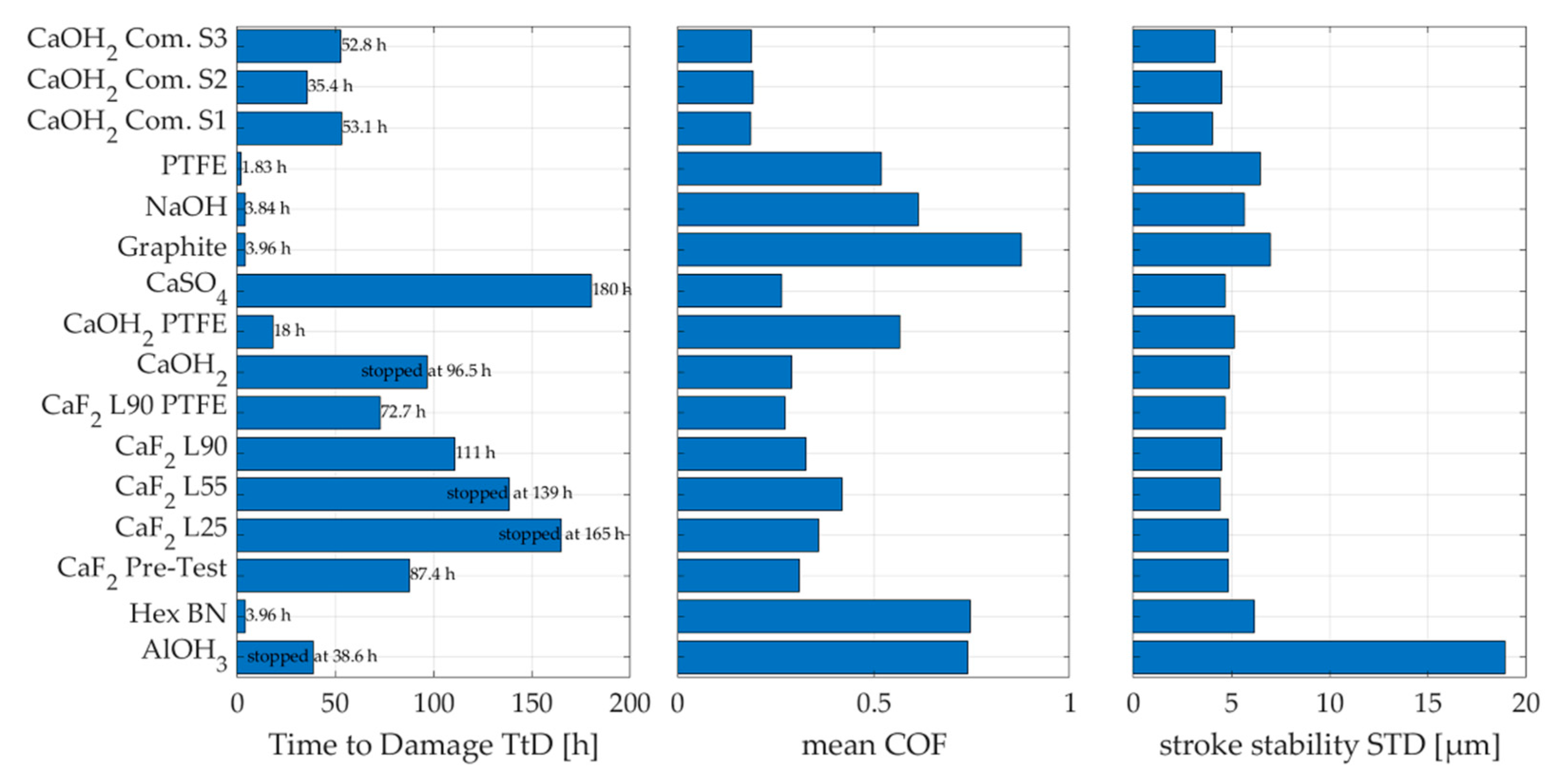
The online and image data of Figure 5 and Figure 6 show the initial damage type on the lubricated test specimen and the initial and progressive damage mechanisms. The different lubricants can be clearly divided into a fretting wear avoidant category and a non-effective category. This can be seen in Figure 7, with bar graphs of the corresponding time to damage (TtD), mean coefficient of friction (COF) and the stroke stability as a measure of any noticeable stick slip. This is the standard deviation of all measured stroke values. Stroke stabilities smaller than 5 µm indicate a stable run without stick slip.
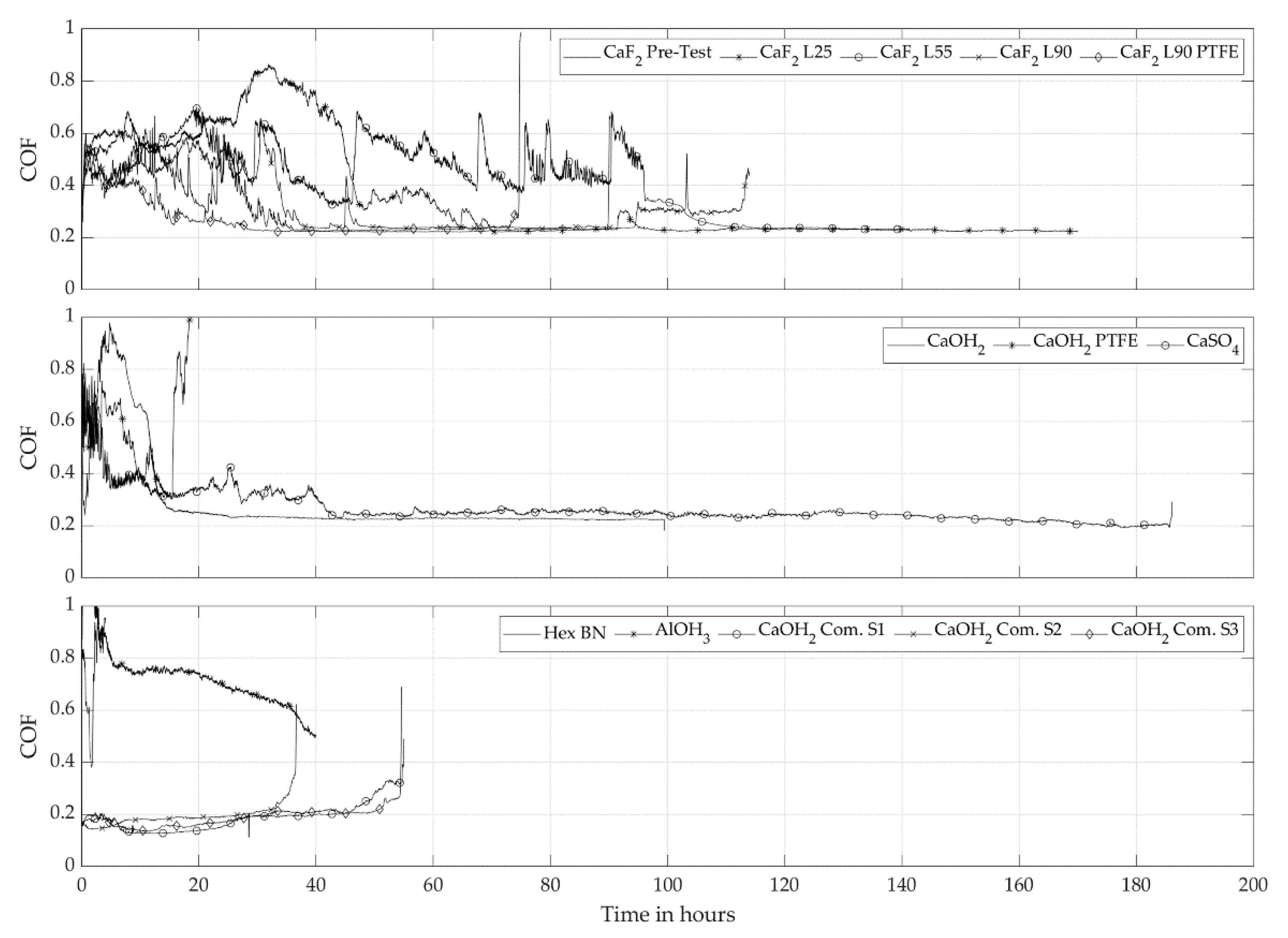
The TtD is a concept where the test is stopped after the rise to a specific friction force or COF level, and the time from the start until this happens is called TtD. As it can be seen in Figure 5, a COF level of 0.2 is often stable for several hours of the runtime. Within such a stable phase, a friction force limit is set on the test bench software to define the end of the test. As a result of a TtD shutdown, the specimen can be analyzed for the wear type leading to high forces, and the TtD value itself can be used for comparison of the different solid lubricants.
PTFE, NaOH, Graphite and h-BN belong to the category of non-effective solid lubricants. All show short run times, and some even show excessive fretting wear and high COF values after a few cycles.
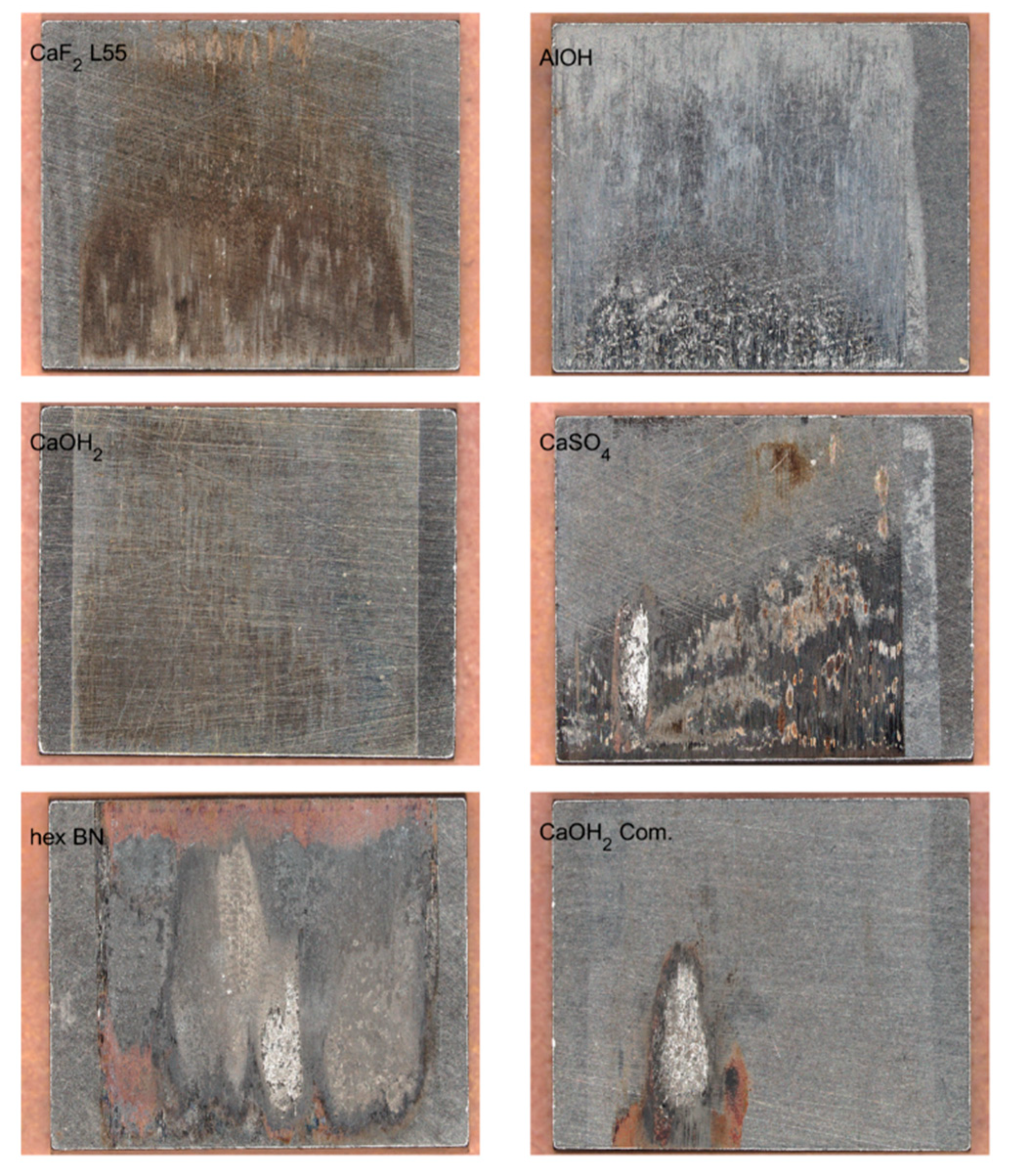
As a benchmark and a comparison to the raw white oil and solid lubricant mix, a commercial Ca(OH)2-containing paste, labeled Ca(OH)2 Com. S1–S3, was tested in three samples, which achieved runtimes reaching 30–50 h until the first major damage with very low COF values. In nearly all cases, the major damage occurred due to an adhesive cold weld, as shown in the lower right image of Figure 6, which led to high friction values. The Ca(OH)2 white oil mix was therefore expected to reach a good performance and lasted 100 h until the test was stopped for surface analysis. A 5 wt.% amount of PTFE in a one-off sample test decreased the performance, but a clear result misses further statistical proof.
CaF2 of different grades is tested (average particle diameters: L25 with 2.5 µm, L55 with 5.5 µm, L90 with 9.0 µm), the finer L25 particles showed a better time to damage trend in comparison to the coarser grades. L90 was also tested after the addition of 5 wt.% PTFE, and also here, a lower TtD was observed.
CaSO4 lasted 180 h with an exceptional long steady state of the observed surface and friction level. Figure 6 shows this state with the additional cold weld on the lower left, which formed in the last minutes of this test.
In Figure 5, graphs of the raw Ca(OH)2, CaF2 and CaSO4 pastes also show a significantly higher COF level at the start, which in most cases stabilized over the course of the experiment. This could last for up to 50% of the TtD. The commercial Ca(OH)2 paste appeared with the most stable performance, which is preferable for a defined friction behavior in an application.
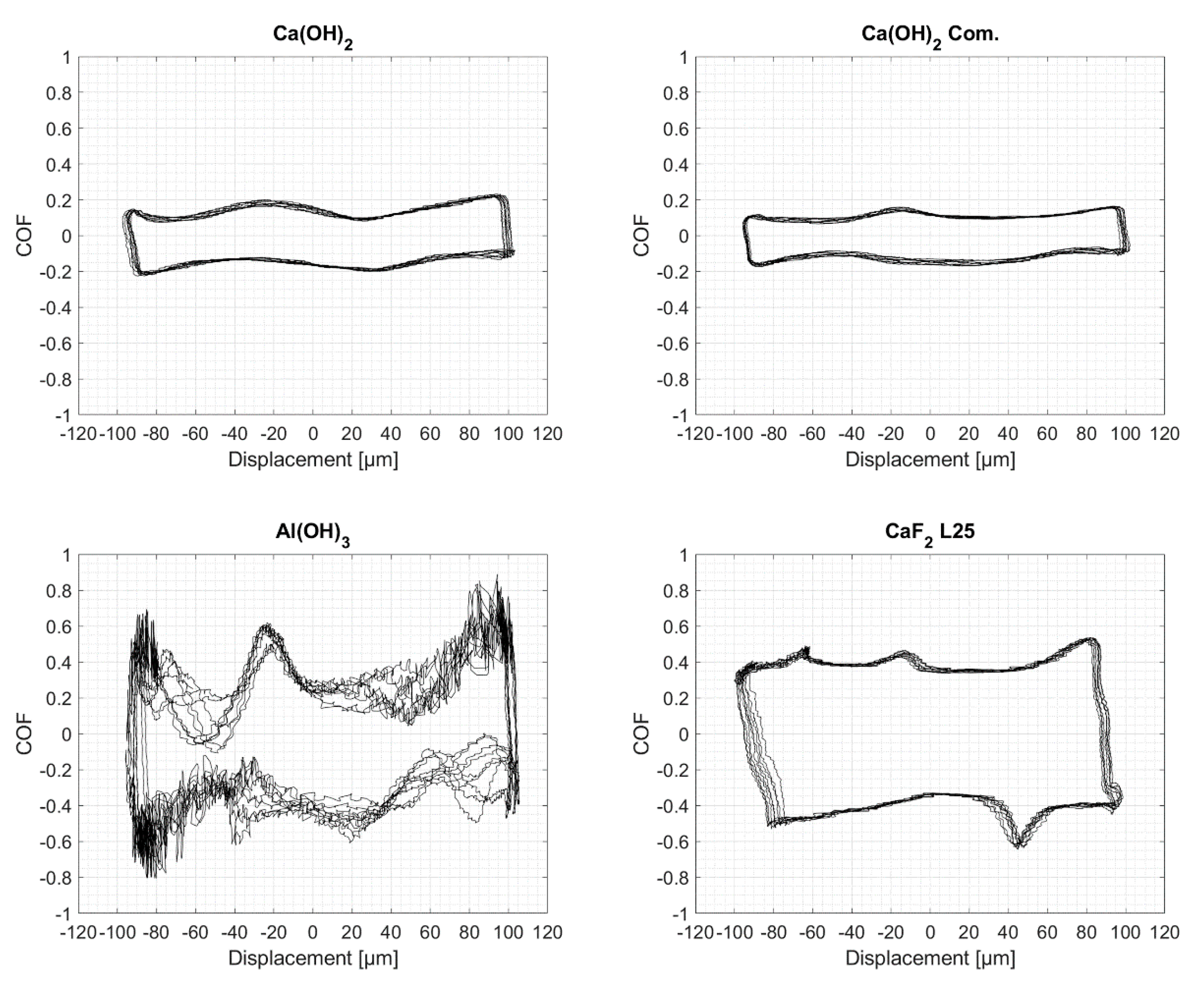
Al(OH)3 depicted the most unusual behavior in this test series. The COF levels and the stroke stability as a measure of the stick slip were very high and stayed at those levels for around 40 h until the test was stopped for analysis. Furthermore, the Al(OH)3 image in Figure 6 indicates no major wear. The fretting loop data of Figure 8 shows also a very dynamic behavior for Al(OH)3 compared to the similar Ca(OH)2 variants. This first result intends that Al(OH)3 may be suited to achieve high friction fit capabilities, which can decrease the likeliness of fretting wear. Figure 8 also shows that the tests are within the gross slip fretting regime–elastic deformation is around 5%–10% of the stroke value of 200 µm.
3.2. Analysis of Solid Lubricants Effects of under Fretting Conditions
In general, fretting conditions are known to be very harsh for lubrication access, and different wear mechanisms can occur that can include the formation of microwelds, oxidation of the boundary layer and formation of abrasive particles and surface disruption. It is also well-known that fretting can lead to extreme local temperature on the sliding surfaces, known as “flash temperatures.” These temperature rises, which can increase up to >1000 °C and occur for every rough surface but also for surfaces that are separated by small lubricant particles because the applied load is carried over a few small contact points [13].
Besides the parameters describing the tribological contact, such as contact area, load, frequency and temperature, fretting wear is also strongly impacted by various other parameters [14], e.g., environmental factors such as water or oxygen content. However, the latter aspects are themselves strongly influenced by the geometry of the tribological contact [15]—an “open” geometry, similar to a ball contact, which allows penetration of surrounding air much better than a planar contact over a large area.
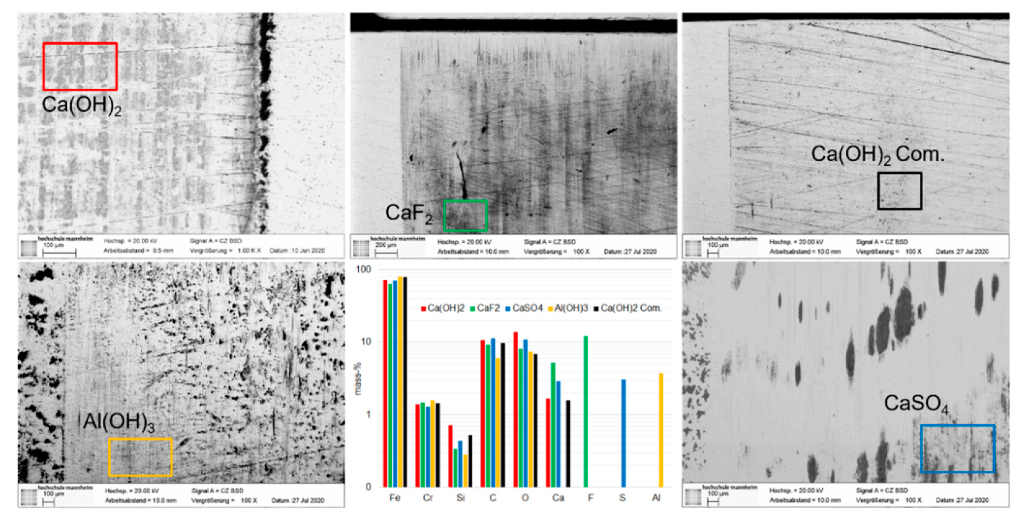
Figure 9 shows an overview of light microscopy images of every promising solid lubricant with a red rectangle marking the SEM/EDX (energy dispersive X-ray spectroscopy) areas. The areas depicting different phenomena have been selected for electron microscopy analysis in order to demonstrate the potential and the versatility, which the fretting test offers together with additional analysis techniques. In the following, a brief overview of the tested solid lubricants is given, and the potential lubrication effects are initially discussed.
3.2.1. h-BN, Graphite, PTFE
The lubricity of some of the best-known solid lubricants (such as graphite, h-BN or MoS2) is attributed to their layered lattice structure. Due to weak chemical interactions, the plate-like particles of these materials can align themselves towards a sliding motion and do thus lead to low friction values. While graphite is known to provide lubrication to temperatures up to 400 °C but then tends to oxidize and lose lubricity, h-BN is known to be chemically inert and stable up to 1000 °C [16].
Mixtures from graphite and hexagonal boron nitride (h-BN) were analyzed in the fretting wear test rig. In both cases, strong wear occurred already after less than one hour of testing. Friction levels were extremely high from the beginning of the test. It is known that both lubricants, however, display high friction coefficients and production of wear in dry air, inert atmospheres or vacuum and lead to early failure. In this case, the absence of oxygen and water, due to the characteristics of the tribological contact situation, might be a feasible explanation for the observed behavior.
Additionally, tests with PTFE as a solid organic lubricant failed early. After 0.5 h, friction and temperature increased continuously, which indicates a proceeding loss of lubrication. Since the polymer is expected to be chemically indifferent towards the existing conditions, the root cause for the early failure can be attributed to the limitations of the load capacity.
3.2.2. Calcium Hydroxide, Ca(OH)2
In commercial antiseizing pastes, calcium hydroxide is commonly used as a lubricant to efficiently separate surfaces under extreme conditions. While most available literature on calcium hydroxide is patent-based, technical literature also describes the remarkable lubrication properties of its lubricant pastes [5,17,18]. Tests performed in this study clearly displayed the beneficial properties of the solid lubricant for fretting conditions. After a short period of unstable and high friction, during which no signs of wear could be observed, the test continued at constantly low friction until it was stopped after 100 h duration. The microscopic analysis showed the formation of a tribolayer, which was further explored by SEM/EDX.
The chemical analysis clearly indicates calcium as being a constituent. The main ratio, however, seems to be iron oxide (see Figure 10). Literature reported that the presence of calcium hydroxide supports the formation of more mechanically stable Fe3O4 modification [7]; however, it was not possible to analyze to what extent that might have happened. Further analysis with RAMAN spectroscopy could lead to further insight into the composition of tribolayers [19,20].
3.2.3. Calcium Fluorite, CaF2
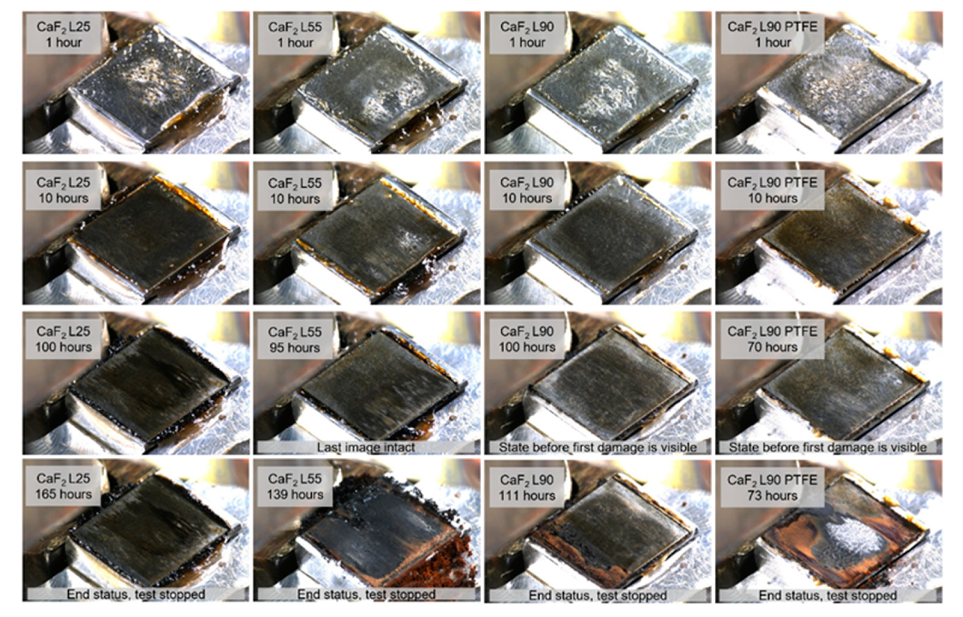
Calcium fluoride, also known as fluorspar, has been known as a high-temperature lubricant for decades [21,22]. Similar to calcium hydroxide, its beneficial properties evolve only at higher temperatures and pressures, and hence, it currently finds application in material composites for grinding, for dry running materials or in antiseizing pastes. However, its use as an additive for greases [23] or polymers [24] has also been investigated. Similar to calcium hydroxide, fluorspar showed an impressive tribolayer built-up performance during the fretting tests, as can be seen in the time-lapse extracts of Figure 11.
Three types of natural CaF2 that differed in particle size were tested. The running-in period with high and unsteady friction lasted 40–55 h, and only small signs of wear could be found. Afterwards, the test continued to run at low friction levels until it was stopped without significant damage after 140–180 h.
The time-lapse images indicate that the change in friction level goes along with changes in the steel surface structure. For the method of contact-opening and intermediate image acquisition, Figure 11 gives good feedback on initial conditions on the first cycles depicted in the first row as well as the tribolayer formation in the following rows. Additionally, the tribolayer intensity (dark surface) under visible light conditions varies clearly with the used CaF2 particle size. The images shown give a high-level overview of tribolayer formation. Image details have more information to be viewed and interpreted in the future.
Further microscopy pictures clearly showed the formation of a tribolayer, and SEM/EDX confirmed larger amounts of Ca, Fe, F, O and C as constituents. The presence of carbon can likely be attributed to remainders of the white oil. The investigation of the exact composition of the tribolayer was not part of this work’s scope; however, the literature describes the formation of FeF3 species as part of the films that form with CaF2 on iron surfaces [25].
The presence of Ca as part of the film suggests the presence of CaF2, but also an oxide-containing Ca compound might have formed. Wang et al. explain the strong tribological performance of fluorspar at elevated temperatures with a transition of the mineral from a brittle to a plastic state [23]. Indeed, the phase diagram displays such a transformation at high pressures and high temperatures, where a phase change into the amorphous PbCl2 structure occurs [26]. The formation of this structure modification might favor the formation of the tribolayers and helps to reduce friction. The extreme conditions required to initiate this phase transformation might have been existent due to the long test period with high and unsteady friction levels, where the interface was subject to high local loads and likely extreme flash temperatures.
Differences in the transfer film formation properties of the calcium fluoride types of different particle sizes were found during the experiments. The transfer films formed fastest during the experiment with the smallest CaF2 particles. A more dedicated analysis with the described approach is planned to establish further insights.
3.2.4. Calcium Sulphate, CaSO4
The formation of calcium sulphate as a reaction product of CaF2 and WS2 at high temperatures and its efficient lubrication properties have been described elsewhere [27]. Experiments performed in the context of this study revealed a very strong performance, also under fretting conditions. After a short time of unstable and high friction, where the time-lapse shows agglomeration of particles and of mild abrasive wear, the test continued before it was stopped after ca. 180 h with sudden adhesion damage. Microscopic analysis showed the formation of tribolayer “isles,” and SEM/EDX analysis confirmed the presence of Ca, S, Fe and O. At this stage, it can only be postulated that the film consists of different metal oxides and sulphates. The reference of CaF2 and WS2 in the literature gives an interesting outlook on a possible binary solid lubricant system, which may also have an effect on avoiding fretting wear.
3.2.5. Aluminum Hydroxide, Al(OH)3
Aluminum hydroxides, such as gibbsite, bayerite or boehmite, are not regarded as typical solid lubricant compared to the previously discussed materials. They do inhibit a layered lattice structure and have, e.g., been discussed as a lubricant between oxide surfaces or as binder material for MoS2 [28,29,30]. However, it is also known that the aluminum hydroxides can transform into Al2O3 when being mechanically activated, and corundum is known as an extremely hard and abrasive mineral [31,32]. Experiments in the fretting wear test rig with Al(OH)3 (gibbsite/hydrargillite) displayed extremely high friction coefficients immediately after start, but, within the first hour of the test, the friction was reduced to a lower and constant level but still high compared to the other solid lubricants. The test was stopped after 40 h, and only minor signs of wear could be observed on the specimen. SEM pictures show the formation of especially larger particle-like aggregates, which consisted of mainly Fe, Al and O according to EDX analysis.
4. Discussion
The new method of material and lubricant testing offers advanced opportunities to witness the mechanisms, which cause the evolution of wear within a planar contact. The trade-off while opening must be regarded very well, as some thinner lubricants may have a chance to reenter the tiny clearance. The acquired images give direct feedback, what type of wear is occurring or if the specimens are still intact with minor wear.
By comparing different methods for fretting wear testing of Heinz [4], Schneider [5] and from the early literature research of Simon [3], a trend is visible to the simplest model system with a ball on a plate. The systematic approach and abstraction process in tribology of Czichos and Habig [8] may not lead to such a simple contact setup for fretting wear problems since most applications have large conformal or planar contacts [1,3]. The new method, therefore, provides a very simple test with planar specimens.
The presented test results emphasize the potential of solid lubricants as efficient materials for surface separation under the specific conditions caused by the minimal clearance between planar specimens. The solid lubricants tested during this study showed different behaviors in the avoidance of fretting wear, and very different tribolayer formations were also seen during the tests. Ca(OH)2 proved to be the benchmark reference for good surface protection. The explicit high-temperature lubricant CaF2 also performed well on fretting wear, not needing high-mass temperatures but eventually the intense local interactions in fretting conditions to form a strong tribolayer. CaSO4 formed tribolayer isles and mild abrasion but effectively avoided typical adhesion for a long time. Tests with Al(OH)3 yielded mild abrasive wear, while the friction levels were comparatively high. This could be of possible use for friction fit pastes.
The presented results mean a working hypothesis for future studies that aim to understand how solid lubricants provide protection against fretting wear. Natural fluorspar (CaF2, Sachtleben Minerals) attracted particular interest with its very distinct tribolayers-a further exploration of its properties might bring deeper insight regarding potential fields of application as a solid lubricant.
Future research should also focus on specific aspects about the formation and the composition of tribolayers of each solid lubricant, considering application conditions and requirements. Additional lubricant formulations to improve or speed up the formation must be analyzed at lower or higher frictions levels.
The new method of fretting wear testing with planar contacts shows a good differentiation of the performance of the solid lubricants by delivering friction forces under dynamically variable displacement and normal forces. Furthermore, the additional opening of the contact gives insight into the tribolayer formation and indications of the major causes of damage. It must be discussed if the opening affects the tribosystem in any way. Only for two short test series, one with non-lubricated materials test and one lubrication paste, a comparison was performed [33] and showed nearly no differences in the results. A general statement on the effects of the intermittent contact-opening for observation must be conducted with further experiments. It is estimated that only tribosystems with low-atmospheric interaction and high-viscosity fluid lubricants differ minimally if the contact is opened.
Author Contributions
Conceptualization, H.B. and E.H.; Data curation, H.B.; Formal analysis, H.B.; Investigation, H.B.; Methodology, H.B.; Project administration, E.H.; Resources, F.S.; Supervision, E.H.; Writing—original draft, H.B. and F.S.; Writing—review & editing, H.B. and F.S.; All authors have read and agreed to the published version of the manuscript.
Funding
This research received no funding.
Institutional Review Board Statement
Not applicable.
Data Availability Statement
Please contact the corresponding author for data. All datasets of online measurements and time lapse images can be provided. The large datasets are not permanently hosted.
Conflicts of Interest
The authors declare no conflict of interest.
References
- Bartel, A. Passungsrost bzw. Reiboxydation, Besondere Verschleissprobleme. Erfahrungsberichte; Allianz Versicherungs-AG: Munich, Germany, 1965. [Google Scholar]
- Heinz, R. Schwingverschleiß-Erscheinungsformen—Prüfmethoden und Abhilfemaßnahmen. Mater. Werkst. 1989, 20, 14–20. [Google Scholar] [CrossRef]
- Simon, R.; Schmitt-Thomas, G. Reibkorrosion—Literaturrecherche; FVA-Number 313; Forschungsvereinigung Antriebstechnik e.V.: Frankfurt, Germany, 1990. [Google Scholar]
- Sommer, K.; Heinz, R.; Schöfer, J. Verschleiß Metallischer Werkstoffe; Springer: Berlin, Germany, 2010; ISBN 978-3-8351-0126-5. [Google Scholar]
- Busch, C.; Weber, S.; Schneider, R. Fundamental Studies on Tribolayers Created by Lubricating Pastes with New Additive Packages; Industrial Lubrication and Tribology; Emerald Publishing Limited: Bingley, UK, 2017; Volume 69, ISBN 0036-8792. [Google Scholar]
- Schlarb, A.; Friedrich, K. Tribology of Polymeric Nanocomposites: Friction and Wear of Bulk Materials and Coatings; Elsevier: Amsterdam, The Netherlands, 2008. [Google Scholar]
- Mang, T.; Dresel, W. Lubricants and Lubrication; Wiley-VCH: Weinheim, Germany, 2017. [Google Scholar]
- Czichos, H.; Habig, K.-H. Tribologie-Handbuch; Springer: Berlin/Heidelberg, Germany, 2015; ISBN 978-3-8348-1810-2. [Google Scholar]
- Cai, Z.B.; Zhu, M.H.; Yang, S.; Xiao, X.B.; Lin, X.Z.; Yu, H.Y. In situ observations of the real-time wear of PMMA flat against steel ball under torsional fretting. Wear 2011, 271, 2242–2251. [Google Scholar] [CrossRef]
- Luo, D.B.; Fridrici, V.; Kapsa, P. Solid Lubrication in Fretting. In Encyclopedia of Tribology; Wang, Q.J., Chung, Y.W., Eds.; Springer: Boston, MA, USA, 2013. [Google Scholar]
- Luo, D.B.; Fridrici, V.; Kapsa, P. Selecting solid lubricant coatings under fretting conditions. Wear 2010, 268, 816–827, ISSN 0043-1648. [Google Scholar] [CrossRef]
- Schneider, R.; Goerz, T.; Biehl, B. Pastes and Grease Pastes. In Encyclopedia of Lubricants and Lubrication; Mang, T., Ed.; Springer: Berlin/Heidelberg, Germany, 2014. [Google Scholar]
- Podgornik, B.; Kalin, M.; Vižintin, J.; Vodopivec, F. Microstructural Changes and Contact Temperatures during Fretting in Steel-Steel Contact. ASME Trans. 2001, 123, 670–675. [Google Scholar] [CrossRef]
- Dobromirski, J. Variables of fretting process: Are there 50 of them? In Standardization of fretting fatigue test methods and equipment. ASTM Spec. Tech. Publ. 1992, 1159, 60–66. [Google Scholar]
- Warmuth, A.; Shipway, P.; Sun, W. Fretting wear mapping: The influence of contact geometry and frequency on debris formation and ejection fora steel-on-steel pair. Proc. R. Soc. A 2015, 471, 20140291. [Google Scholar] [CrossRef] [Green Version]
- Bhushan, B. Modern Tribology Handbook; CRC Press: Boca Raton, FL, USA, 2001. [Google Scholar]
- Gänsheimer, J.; Holinski, R. A Study of Solid Lubricants on Oils and Greases under Boundary Conditions. Wear 1972, 19, 439–449. [Google Scholar] [CrossRef]
- Gänsheimer, J. On the Lubricating Properties of Mixtures of Mineral Oil with certain Inorganic Phosphates, Hydroxides, and Sulfides. Asle Trans. 1971, 15, 201–206. [Google Scholar] [CrossRef]
- Schmid, T.; Dariz, P. Shedding light onto the spectrum of lime: Raman and luminescence bands of CaO, Ca(OH)2 and CaCO3. J. Raman Spectrosc. 2015, 46, 141–146. [Google Scholar] [CrossRef]
- Li, Y.S.; Church, J.S.; Woodhead, A.L. Infrared and Raman spectroscopic studies on iron oxide magnetic nano-particles and their surface modifications. J. Magn. Magn. Mater. 2012, 324, 1543–1550. [Google Scholar] [CrossRef]
- Mohan, S. Calcium Fluoride a Potential Solid Lubricant for Green Tribology and Sustainability. In Recent Advances in Mechanical Engineering; Kumar, H., Jain, P., Eds.; Springer: Singapore, 2020. [Google Scholar]
- Clauss, F.J. Solid Lubricants and Self Lubricating Solids; Academic Press: Cambridge, MA, USA, 1972. [Google Scholar]
- Wang, L.; Wang, B.; Wang, X.; Lu, W. Tribological Investigation of CaF2 Nanocrystals as Grease Additives. Tribol. Int. 2007, 40, 1179–1185. [Google Scholar] [CrossRef]
- Adam, A.; Grunthaler, K.H.; Hodes, E. Self-Lubricating Bearing Material and Plain Bearing of Such a Bearing Material. U.S. Patent 6068931, 30 May 2000. [Google Scholar]
- Carzola, C.; Errandonea, D. The high-pressure high-temperature phase diagram of calcium fluoride from classical atomistic simulations. J. Phys. Chem. C 2013, 117, 11292–11301. [Google Scholar]
- Mirwald, P.; Kennedy, G. The Phase Relations of Calcium Fluoride to 60 KBars and 1800 °C. J. Phys. Chem. Solids 1977, 39, 859–861. [Google Scholar] [CrossRef]
- John, P.J.; Prasad, S.V.; Voevodin, A.A.; Zabinski, J.S. Calcium Sulfate as a High Temperature Solid Lubricant. Wear 1998, 219, 155–161. [Google Scholar] [CrossRef]
- Richard, S.G.; Stephen, M.H. Aluminum hydroxides as Solid Lubricants. U.S. Patent 919829A, 24 April 1990. [Google Scholar]
- Fitzsimmons, V.G.; Zisman, W.A. Dry-Film Lubricants from Molybdenum Disulfide bonded with Microfibrous Boehmite. Asle Trans. 1969, 12, 117–128. [Google Scholar] [CrossRef]
- Gates, R.S.; Hsu, S.M.; Klaus, E.E. Ceramic Tribology: Methodology and Mechanisms of Alu-Mina Wear; NIST Special Publication 758: Washington, DC, USA, 1988. [Google Scholar]
- Tonejc, A.; Stubicar, M.; Kosanović, K.; Subotić, B.; Smit, I. Transformation of γ-AIOOH (boehmite) and AI(OH)3 (gibbsite) to a-AI2O3 (corundum) induced by high energy ball milling. J. Mater. Sci. Let. 1994, 13, 519–520. [Google Scholar] [CrossRef]
- Alex, T.C.; Kumar, R.; Roy, S.K.; Mehrotra, S.P. Mechanically Induced Reactivity of Gibbsite: Part 1. Planetary Milling. Powder Technol. 2014, 264, 105–113. [Google Scholar] [CrossRef]
- Buse, H.; Hodúlová, E. Fretting Wear Observation in Plane Metal to Metal Contacts. In Proceedings of the 22nd International Colloquium Tribology; Technische Akademie Esslingen e.V.: Ostfildern, Germany, 2020. [Google Scholar]
Figure 1.
(a–f) Fretting wear of different machine elements [1] and (g) loss due to fretting wear.
Figure 1.
(a–f) Fretting wear of different machine elements [1] and (g) loss due to fretting wear.

Figure 2.
(a) The test bench, (b) sample contact size, (c) alignment test and (d) sample relative motion.
Figure 2.
(a) The test bench, (b) sample contact size, (c) alignment test and (d) sample relative motion.

Figure 3.
Contact-opening schematic (a) and intermediate images (b–k) of the CaSO4 Test.

Figure 4.
Exemplary fretting loop for high friction with low stroke (a) and low friction with high stroke (b).
Figure 4.
Exemplary fretting loop for high friction with low stroke (a) and low friction with high stroke (b).

Figure 5.
COF-Data.

Figure 6.
Lower specimen microscopy after the test.

Figure 7.
The time to damage, mean coefficient of friction and stroke stability (standard deviation).
Figure 7.
The time to damage, mean coefficient of friction and stroke stability (standard deviation).

Figure 8.
Fretting loops for variants of Ca(OH)2, CaF2 and Al(OH)3.

Figure 9.
Microscopy overview of layers from solid lubricants and area designation for SEM/EDX.

Figure 10.
EDX of transfer films visible on backscatter electron images.

Figure 11.
Selected contact-opening interval images of CaF2 tests, lower specimen. Every column is a single test and every row indicates approx. equal runtime until failure.
Figure 11.
Selected contact-opening interval images of CaF2 tests, lower specimen. Every column is a single test and every row indicates approx. equal runtime until failure.


Table 1.
Test series data.
| Solid Lubricant | Mohs Hard. | Mix [wt.%] | No. of Samples |
|---|---|---|---|
| Calcium fluorite/CaF2 of different coarseness * | 4 | 50 Solid Lubricant, 50 white oil | 4 |
| Calcium hydroxide/Ca(OH)2 | 2 | 50 SL, 50 white oil | 1 |
| Ca(OH)2–commercial product | 2 | 15 to 25 SL acc. to SDS ** | 3 |
| Aluminum hydroxide, Gibbsite/Al(OH)3 | 50 SL, 50 white oil | 1 | |
| Natrium hydroxide/NaOH | 50 SL, 50 white oil | 1 | |
| Hexagonal boron nitride/h-BN | 30 SL, 70 white oil | 1 | |
| PTFE | 50 SL, 50 white oil | 1 | |
| Graphite | 30 SL, 70 white oil | 1 | |
| Calcium sulphate CaSO4 | 50 SL, 50 white oil | 1 |
Similar for all tests: Pair of lapped 100Cr6/1.3505 Steel specimens with 60–62 HRC, 64 mm2 contact area, 15.6 MPa/1 kN normal load, 200 µm stroke at 49.5 Hz frequency and the temperature of the specimens of 80 °C; * Natural CaF2 (Sachtleben Minerals), ** Safety Data Sheet.
Publisher’s Note: MDPI stays neutral with regard to jurisdictional claims in published maps and institutional affiliations. |
© 2021 by the authors. Licensee MDPI, Basel, Switzerland. This article is an open access article distributed under the terms and conditions of the Creative Commons Attribution (CC BY) license (https://creativecommons.org/licenses/by/4.0/).
Share and Cite
MDPI and ACS Style
Buse, H.; Schueler, F.; Hodúlová, E. Planar Contact Fretting Test Method Applied to Solid Lubricants. Lubricants 2021, 9, 58. https://0-doi-org.brum.beds.ac.uk/10.3390/lubricants9060058
AMA Style
Buse H, Schueler F, Hodúlová E. Planar Contact Fretting Test Method Applied to Solid Lubricants. Lubricants. 2021; 9(6):58. https://0-doi-org.brum.beds.ac.uk/10.3390/lubricants9060058
Chicago/Turabian StyleBuse, Henrik, Fabian Schueler, and Erika Hodúlová. 2021. "Planar Contact Fretting Test Method Applied to Solid Lubricants" Lubricants 9, no. 6: 58. https://0-doi-org.brum.beds.ac.uk/10.3390/lubricants9060058
Note that from the first issue of 2016, this journal uses article numbers instead of page numbers. See further details here.