Wear Resistance of TiAlCrSiN Coatings Deposited by Means of the Co-Sputtering Technique
by
Fredy Antonio Estupiñan
1, 
Carlos Mauricio Moreno
2,
Jhon Jairo Olaya
3 and
Luis Carlos Ardila
1,* 1
Dirección de Posgrados, Universidad ECCI, Cra 19 No 49-20, Bogotá 111311, Colombia
2
Grupo de Integridad y Evaluación de Materiales GIEM, Universidad Pedagógica y Tecnológica de Colombia, Tunja 150003, Boyacá, Colombia
3
Departamento de Ingeniería Mecánica y Mecatrónica, Universidad Nacional de Colombia, Bogotá 111321, Colombia
*
Author to whom correspondence should be addressed.
Lubricants 2021, 9(6), 64; https://0-doi-org.brum.beds.ac.uk/10.3390/lubricants9060064
Submission received: 30 April 2021
/
Revised: 27 May 2021
/
Accepted: 30 May 2021
/
Published: 21 June 2021
(This article belongs to the Special Issue Tribological Applications of Nano & Submicro Structured Materials)
Abstract
:TiAlCrSiN thin films were deposited on K20 WC–Co substrates using the co-sputtering method. The silicon content in the deposited coatings were varied by modifying the number of silicon pieces (1, 2, or 3) on the Cr target. The morphology, semi-quantitative chemical composition, and microstructure were investigated using scanning electron microscopy (SEM), energy disperse spectroscopy (EDS), and X-ray diffraction (XRD), respectively. Modified ASTM B611 abrasive wear and nano-hardness tests were used to evaluate the tribological and mechanical properties of the different coatings, respectively. The results showed that the addition of Si promotes an increased hardness and elastic modulus. Also, mass loss in wear tests decreased as Si increased, due to the growth in hardness related to the microstructural refinement produced by the blocking of sliding bands by the grain boundaries.
1. Introduction
Cemented tungsten carbide is widely known for its exceptional hardness and toughness, which make it suitable for cutting operations where extensive stress is generated. This material has been widely used in the hard metal industry for the manufacturing of cutting tools, drilling bits, mining, and highly wear-resistant parts. Despite that, this behaviour does not suffice for wear associated with diffusive phenomena, chemical chip reactions, or oxidation [1,2]. For this reason, the use of coatings arises as a good alternative for improving tool performance. The coating material in contact with the chip must be chemically stable at the temperatures generated during cutting and must, of course, be resistant to oxidation so that it adheres strongly to the carbide substrate. After meeting these three minimum requirements, the coating acts as a barrier against diffusive phenomena (the elements that constitute the tool or environmental oxygen), which lead to a drastic reduction in cutting-edge wear.
Hard coatings were developed mainly for cutting-tool applications where high stress, wear, and chemical corrosion are inherent. Nanostructured coatings exhibit attractive properties such as better wear resistance and high-temperature stability, which are ideal for subtractive applications. Some traditional hard ceramics, such as nitrides, carbides, borides, and oxides (TiAlN, TiC, TiB2, and TiO2, respectively), cannot retain their properties under heavy cutting conditions [3]. Therefore, compound materials such as TiAlN, AlCrN, and TiCN, have recently been tested as coating materials for cutting tools [4].
Ternary nitride coatings, such as AlTiN and AlCrN, are widely used in metal cutting operations at the industrial level, mainly due to their high oxidation resistance (up to 800 °C [5] and 900 °C [6], respectively). In both cases, aluminium and chromium oxide films are expected to be thermal barriers and lubricating layers that improve cutting performance. Nevertheless, combined tribological phenomena such as stress, interface temperature, chemical reactivity, and rapid tool wear lead to a short operating tool life. This poses a continuing challenge for maintaining cutting tool integrity, and several laboratory investigations aimed at understanding the physicochemical mechanisms have been carried out [7]. As a result of the numerous tribological tests trying to reproduce the metal cutting conditions, conclusions suggest that there is a combination of chemical, abrasive, and adhesive mechanisms that constitutes the principal source of accelerated wear [8,9].
The search for better materials that function well in extreme conditions with an extended operating life, has led to the incorporation of silicon into these ternary systems and has shown promising results in drilling and cutting operations, where good oxidation resistance and mechanical performance are required [10,11,12,13,14,15,16]. Consequently, coatings with a quaternary system (e.g., AlTiSiN and AlCrSiN) show improved mechanical properties either due to crystallite size refinement or the formation of high-compression residual stresses. Thus, wear resistance improved because of the above-mentioned mechanisms and the formation of stable oxide layers [5,6].
Superior mechanical properties were achieved by forming a nanocrystalline phase (e.g., TiN) embedded in an amorphous phase, Si3N4, according to Veprek et al. [17]. Even though this theory is widely accepted and has been promulgated for many years, there is no agreement on whether the phenomenon related to improved hardness is due to the nanocomposite microstructure or high-compression residual stresses generated by an energetic ion bombardment during deposition [16].
Wear resistance is associated with hardness and stress levels, but it is essential to maintain a balance between high values for those properties and avoiding loss of toughness. Hence, thermal stability and resistance to oxidation are essential. Improving wear resistance, especially at high temperatures [18,19,20,21,22] can be achieved by adding alloying elements such as Al, Cr, C, V, Y, and Zr to coatings of the quaternary order or even higher.
In the present study, a sputtered TiAlCrSiN coating was deposited on WC6Co (a tungsten–carbide substrate) with silicon content varying from 1.4 at% to 7.1 at%. The main purpose was to investigate the influence of the incorporation of silicon on its microstructural and mechanical properties and its relationship with the wear behaviour using the ASTM B 611 modified standard under low conditions.
2. Materials and Methods
2.1. Substrate Preparation
TiAlCrN coatings with differing silicon content were deposited on K20 hard metal substrates, employing the co-sputtering technique. The material selected as the substrate was a submicron hard metal grade containing 6 wt.% Co (HV30: 1650, density: 14,800 Kg/m3). Test specimens were prepared as plates 4 mm high by 13 mm wide. The samples were polished down to 1 μm diamond paste and ultrasonically cleaned in ethanol before coating.
2.2. Coating Deposition
The sputtering was conducted with 270 W pulsed-DC power applied to a TiAl target and RF power ranging between 70 and 170 W applied to a metallic Cr target. Both targets were 101.6 mm diameter and 99.99% pure. The substrate-to-target separation was fixed at 10 cm, with a confocal angle of 60°. During sputtering, the flow rates of argon and nitrogen were 4 and 14 sccm, respectively. The base pressure was 1.08 × 10⁻³ Pa, and the substrate temperature was fixed at 200 °C. The working pressure was kept constant at 0.4 Pa. After 50-min of sputtering, the films were cooled down to room temperature. In the deposition tests, silicon pieces (1, 2, or 3) were positioned equidistantly on the Cr target. The deposition time was fixed at 90 min to obtain coatings with a thickness of approximately 1000 nm as measured by an optical interferometer/microscope (Bruker ContourGT-K).
2.3. Coating Characterization
The microstructure of the as-deposited samples and the wear test samples was examined using a PHENOM pro X scanning electron microscope (SEM) equipped with energy-dispersive spectroscopy (EDS) analysis. Phase identification was carried out via X-ray diffraction (XRD) with a PANalytical X’pert pro with Ni-filtered Cu Kα radiation operating at 40 kV and 40 mA using parallel beam glancing incidence geometry. In this configuration, diffraction occurs at a small, constant penetration depth since a constant incident angle is used (in our case, ω = 3°). The scanning range varied from 20° to 90°, with a step size of 0.02° and a time per step of 1 s. The crystallite size contributions were calculated using Williamson-Hall methodology with the additive Cauchy (Lorentz) equation to fit broadening diffraction peaks.
2.4. Mechanical Characterization
The nanoindentation tests were performed using a Hysitron TI 750 UBI. For the hardness test, a Berkovich diamond tip with a radius of 200 nm was used by applying a charge of a 600 μN load and 10 s load time with 2 s pause. The procedure was carried out under ambient conditions with a relative humidity of 56% and average temperature of 18.5 °C. For each sample, nine tests were applied to all samples to measure the hardness (H) and reduced modulus (Er), with a minimum distance of 30 μm between indentations. To separate the contributions of the substrate properties in the film measurements, the indentation depth was below 10% of film thickness. Raw hardness and modulus data were achieved from load vs. displacement curves using the method proposed by Oliver and Pharr [1]. Indentation locations were manually selected to avoid the presence of droplets. After testing, all load vs. displacement curves were revised by removing non-valid data.
2.5. Abrasive Wear Test
Volume and mass coating loss was determined using a modified ASTM B611 low-load procedure; after several trial experiments, a 100 N force pushing the specimen and two revolutions at 100 rpm was selected to analyse the coating’s wear behaviour and avoid total coating elimination. The test was performed on one set of representative coating samples, taking into account the maximum relative error of 0.08%. AISI 1020 steel was used as the abrading wheel (with a nominal hardness of 85 HRB) with a 30-mesh solution of alumina particles as an abrasive material. The tests were performed on 16 × 16 × 3 mm samples each having a different silicon content. In accordance with the above-mentioned ASTM standard, test specimens were rinsed with water to remove any grit and then dried. Finally, the specimens were weighed three times on a Sartorius Practum ™ analytical balance (precision of ±0.001 g), and the average weight was taken as the starting weight for calculating weight and volume loss.
3. Results and Discussion
3.1. Microstructure
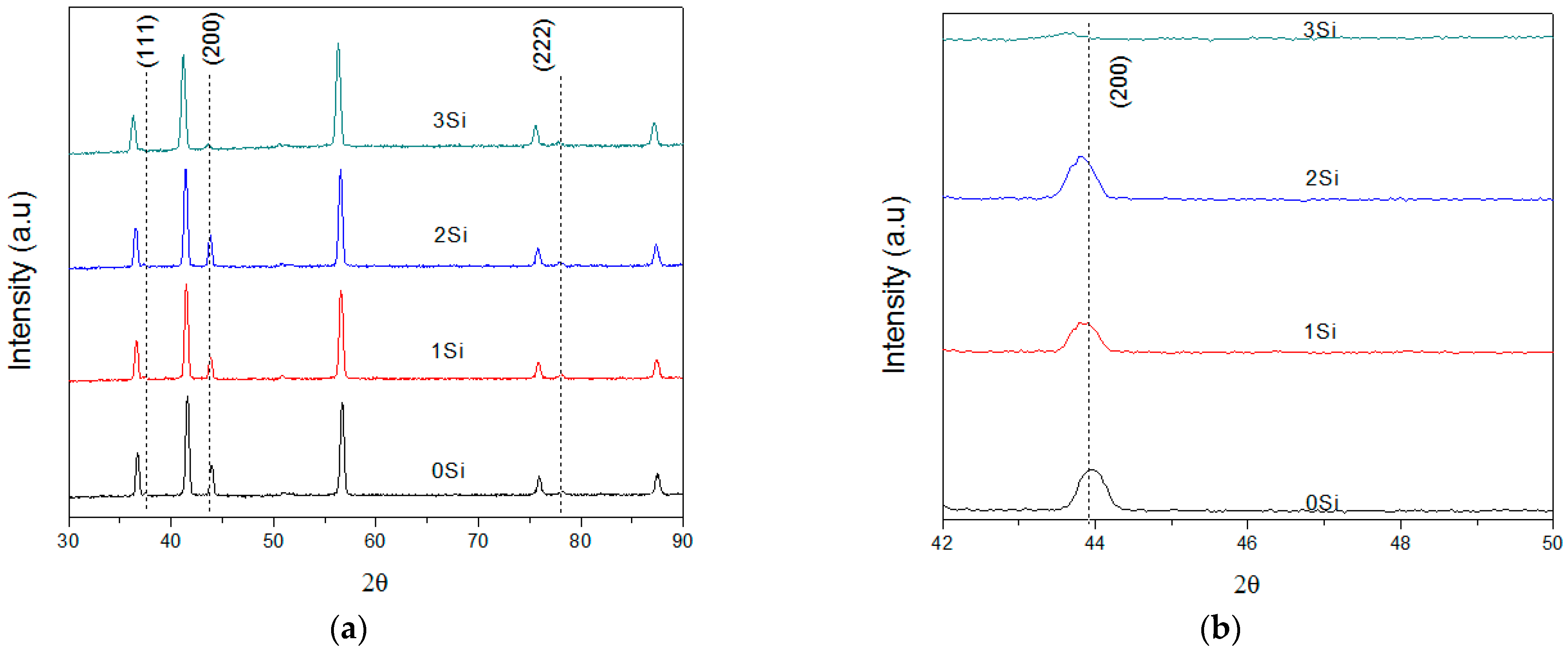
Figure 1 shows the X-ray diffraction patterns for all the coatings. The most relevant peaks and corresponding planes belong to the coatings; the others belong to the WC–Co substrate.
In Figure 1a, the XRD patterns are shown The diffraction peaks observed at 2θ values of 37.5°, 43.9°, and 78.04° correspond to the (111), (200), and (222) planes of TiAlCrN with different silicon content.
Taking the blue lines as a reference in Figure 1a, it is clear that the addition of silicon caused a shift in the diffraction peaks of TiAlCrN to smaller angles. This can be seen in detail for plane (200), shown in Figure 1b, which diffracts at a 2Ɵ angle at approximately 43.94° without any silicon content, but when 1 piece of silicon is added corresponding to 1.67 atomic%, it moves to 43.86°. For 2 pieces at 3.40% silicon, the displacement is at 43.79°, and with the highest silicon content (7.12%), the peak is displaced to 43.64°.
This shift indicates an increase in the lattice parameter, probably caused by the solid solution of TiAlSiN, produced by the incorporation of large Ti atoms into the AlSiN structure [23]. This can be demonstrated by calculating the lattice parameters of the 4 coatings, as shown in Table 1.
These results, calculated from the results obtained from X-ray diffraction, demonstrate the increase in the lattice parameter as the silicon content increases.
Another aspect worth highlighting in the XRD patterns of the coatings is the trend for peaks to broaden with an increase in silicon content. This could be caused by grain refinement [24,25], the presence of intrinsic solid residual stresses [26,27], or an increase in the amorphous phase. Table 2 shows the crystallite size for coatings with different Si content.
The largest crystallite size is present in the TiAlCrN coating without silicon. When one piece of silicon was placed in a DC power source, the size was reduced by almost 3%, reaching 57.3746 nm. A reduction of 17% was calculated using two pieces of silicon compared with the coating in the absence of silicon. Finally, with three pieces of silicon, corresponding to 7 at%, the decrease in crystallite size was 24.50%.
3.2. Mechanical Properties
In general, the mechanical properties of a material should be evaluated simultaneously by its hardness and the elastic modulus. Thus, the ratios of H/E and H3/E2 reflect the elastic strain to failure and plastic deformation resistance of a material, respectively. The (H/E) and the (H3/E2) were calculated based on the hardness and elastic modulus values. Experimental measurement of the elastic limit of deformation was carried out using the H/E ratio, which was applied to the coated surfaces [28]. This relationship takes into account the elastic deformation up to failure. Additionally, the H3/E2 ratio, known as the plastic resistance parameter, is associated with the coating’s resistance to plastic flow [29]. Table 3 shows the mechanical properties of the coatings and the calculation of the relationships between hardness and the elastic modulus. An increase in hardness with the amount of Si in the coating can be seen; furthermore H/E and H3/E2 exhibit the same variation trend as the hardness.
Both H/E and H3/E2 ratios increased with the addition of silicon in the films deposited. The H/E and H3/E2 ratios show a relevant effect on the wear behaviour of the coatings; thus, an increase in these values is correlated with superior wear resistance, associated with higher plastic deformation resistance and fracture toughness [18]. Consequently, it is essential to point out that a change in the mechanical properties of the coatings is closely related to the microstructural changes that the material experienced when silicon was incorporated into the crystal lattice. Thus, taking into account H, H/E, and H3/E2, the TiAlCrSiN coating should exhibit the strongest crack resistance; instead, the TiAlCrN coating may exhibit the poorest crack resistance.
3.3. Wear Behaviour
In Table 4, the wear test results of coatings regarding weight and volume loss are shown.
There is a tendency for mass and volume loss with increasing silicon content. In the TiAlCrN coating, the weight loss is 1 mm3 greater than that for one silicon piece, showing a notable effect of the addition of silicon. The decrease in volume loss was constant as the silicon content increased and reached a maximum with three pieces of silicon, corresponding to 7% atomic concentration. This was consistent with the maximum solubility of silicon in an amorphous structure without a decrease in crystallinity [30].
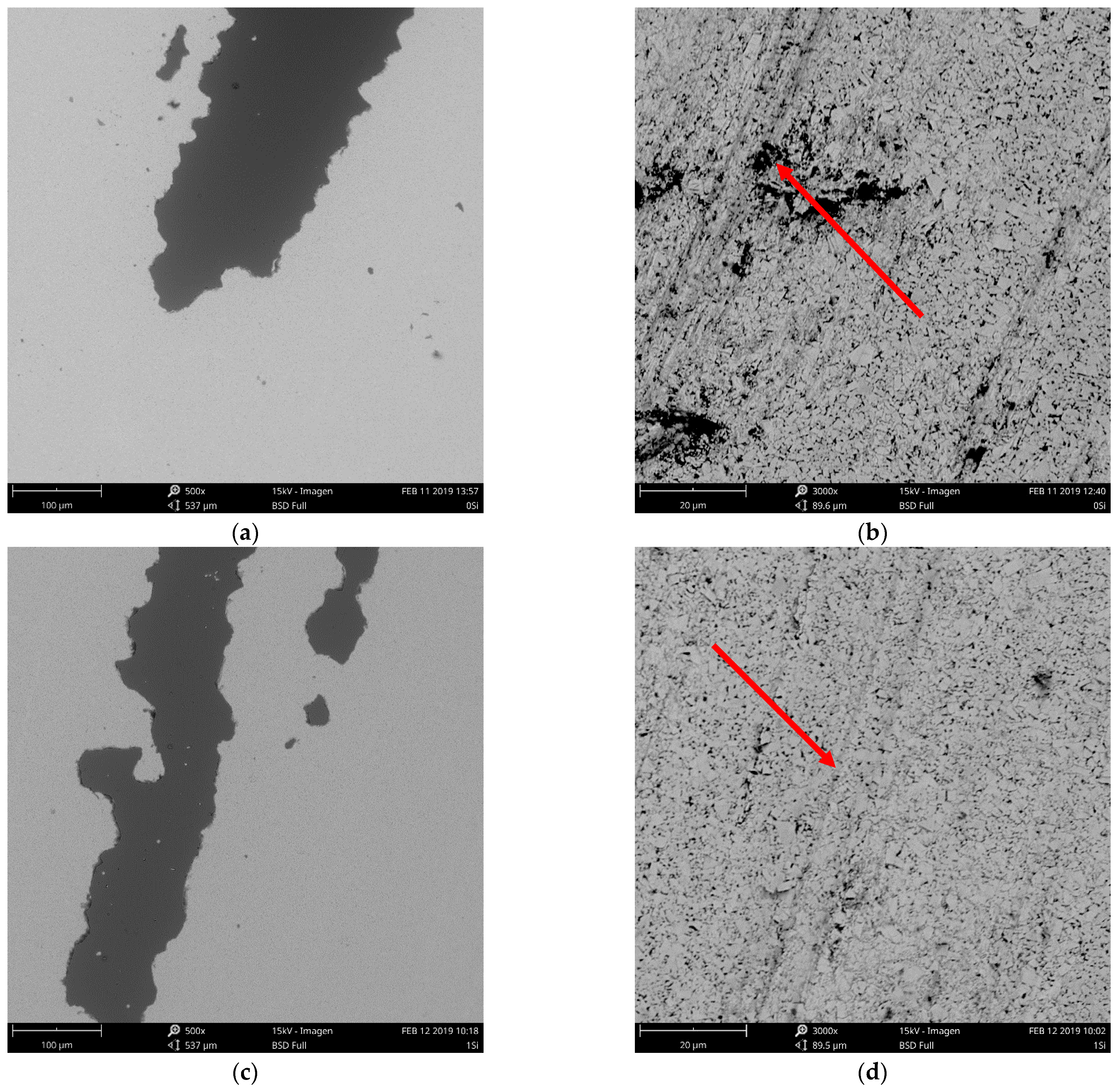
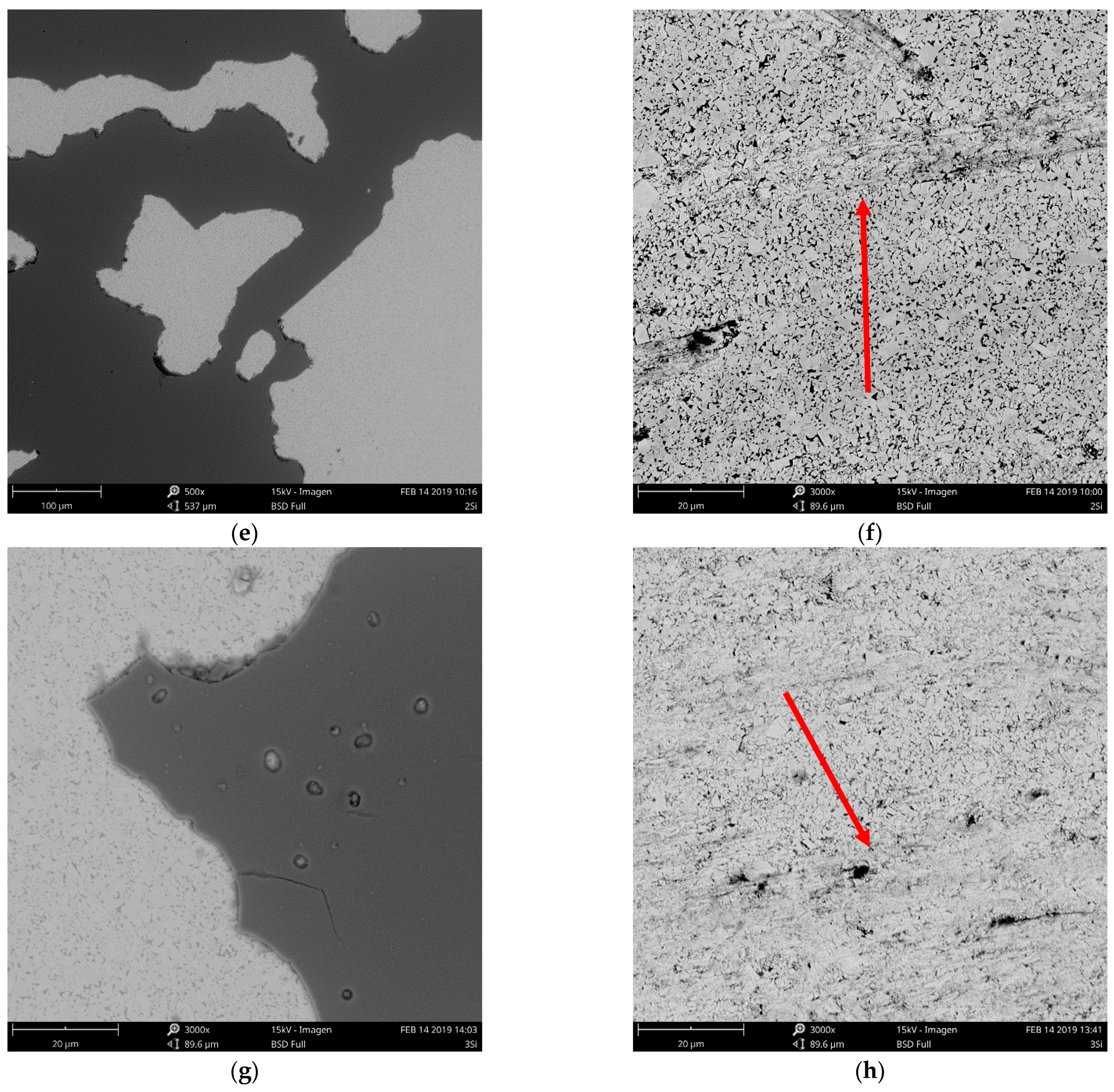
The SEM images in Figure 2 show wear patterns on the substrate (red arrows) and areas where the coating disappeared. No wear marks can be seen on the coating although there are delaminated areas.
In general, the coatings experienced different stages during the wear tests. First, they were subjected to cohesive failure (spalling) due to their high degree of brittleness [31,32,33,34]. Afterward, the adhesive damage associated with detachment or failure of the coating/substrate interface occurred. Eventually, the coating delaminated, and total coating failure occurred. Consequently, the coatings under study exhibited adhesive wear with interface pull-off and delaminated areas.
On the other hand, the marks observed on the substrate (images to the right of Figure 2) suggested slight abrasive wear caused by the sliding contact with the alumina particles on the WC–Co. This wear is characterized by the gradual removal of metallic cobalt particles followed by microscopic fragmentation of the tungsten carbide grains [35].
Abrasive wear occurs when there was an interaction between a hard, rough surface and a soft one in the presence of abrasive material; under the laboratory conditions used in this investigation, alumina was used, which has a lower level of hardness than does K20-quality tungsten carbide (1600 HV vs. 1780 HV); therefore, the wear rate was lower when compared to harder abrasives such as SiC [36].
Finally, to study the wear of the coatings and the effect of silicon in more detail, the delaminated area was calculated by image treatment obtained by optical microscopy. For this, 54 images were taken at 100× magnification for each sample and analysed using Image J® software. These images covered the entire area of the specimen, and the results are shown in Table 5.
The behaviour of the delaminated areas shows greater wear resistance with increased silicon content in the coatings, showing an 8.4% reduction in delaminated area in the coating with 7.1 wt.% of silicon compared with the reference coating without silicon. These results were consistent with the hardness measurements according to the following discussion.
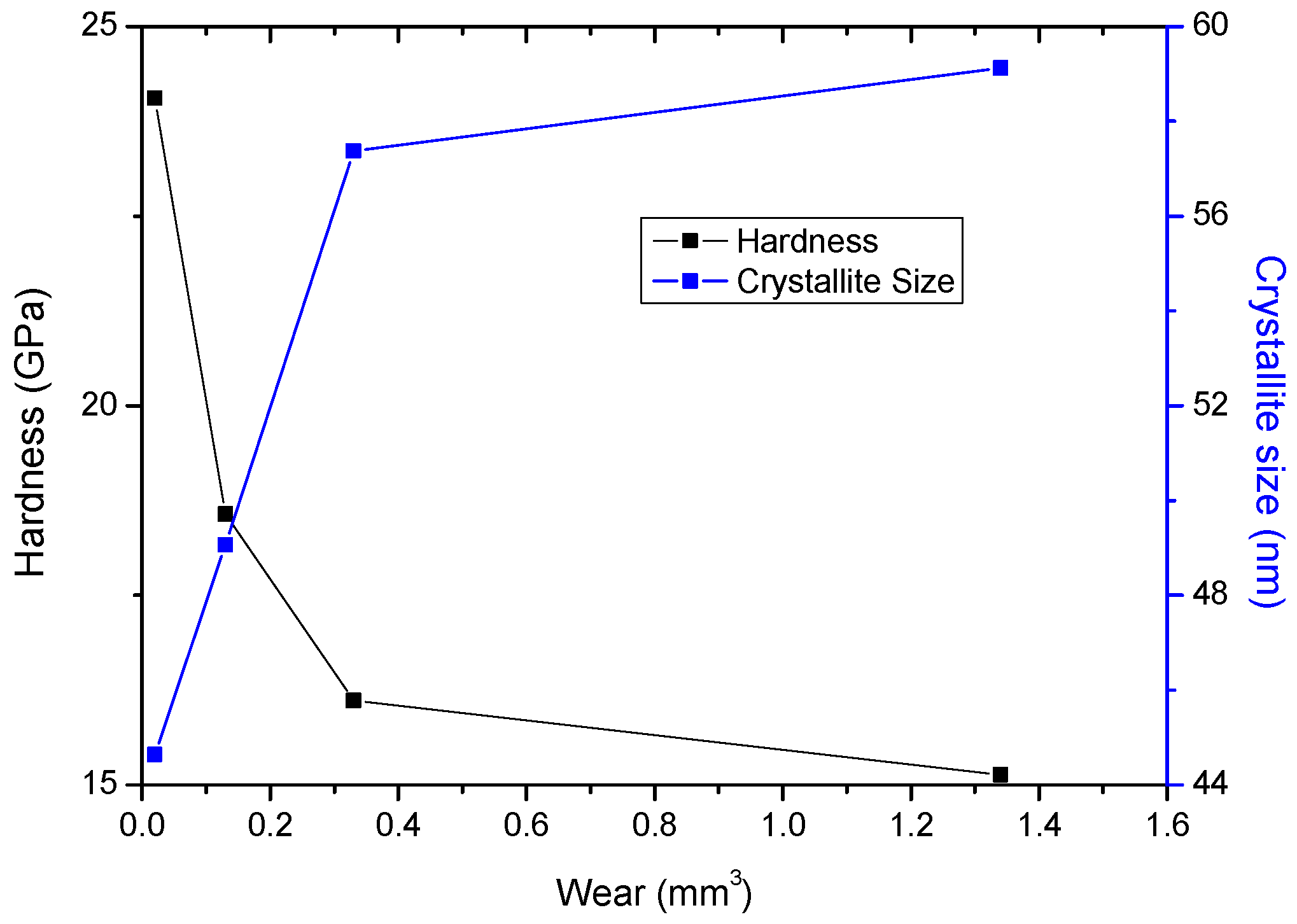
It is well known that there is a close relationship between wear resistance, hardness, and crystallite size. For this reason, these parameters were analysed to determine the connection among them, as shown in Figure 3.
The behaviour of these three properties showed a clear relationship in how increase in hardness with the addition of silicon led to a refinement of crystallite size due to the microstructural phenomena discussed above. Furthermore, the wear results also showed favourable trends: increasing hardness and decreasing crystallite size.
Similar results have been reported by various authors [28,37] who found a connection among the coatings’ chemical composition, mechanical properties, and wear; furthermore, D. Philippon et al. [37] affirmed that an increase in silicon content caused a significant rise in hardness due to a refinement of the crystallite size. These microstructural changes caused lower volume and weight loss in wear tests. This phenomenon may be associated with some theories, as discussed below.
One of these theories is that hardness and the elastic modulus of the material are related, and that they are dependent on the silicon content. That behaviour is because an increase of this element produces hardening via the Hall–Petch effect and an increase in the nanocomposite intergranular phases of the material, which produces improved mechanical properties. Furthermore, it is well known that hard materials exhibit high resistance to wear; in this sense, some authors suggested the importance of the elastic modulus (E) in the wear resistance of materials [28]. Thus, wear is related to the elastic deformation limit, characterized by the material’s ability to be deformed and recover without experiencing permanent (plastic) deformation.
To summarize, the role of silicon in the wear resistance of coatings can be understood from two points of view. First, the change in the microstructure (grain refinement) when adding silicon caused an increase in mechanical properties; second, the possible formation of an amorphous phase reduces the development of high-compression residual stresses, which promotes superior performance [37].
4. Conclusions
Coatings deposited on K20 tungsten carbide exhibited a B1 NaCl cubic structure. In all cases, the lattice parameter increased with the incorporation of silicon into the FCC crystal structure. Also, the decrease in crystallite size was calculated and was congruent with the increase in hardness and elastic modulus. The effect of the addition of silicon to the crystallite refinement is not clear; however, the theory concerning an increase in hardness as a result of the microstructural refinement produced by the blocking of the sliding bands by the grain boundaries becomes relevant.
The ASTM B611 standard was modified to determine the wear in coatings caused by changes to the load, wheel speed, and revolutions. With these adaptations, the wear parameter of the coatings was obtained, and the results showed a close relationship with the mechanical properties. Thus, reductions in mass and volume were observed when the silicon content increased in the TiAlCrN coatings, which matched the increase in hardness and elastic modulus. Moreover, the values of H/E and H3/E2 exhibited the same variation as H after silicon was added to the TiAlCrN coating. Thus, the TiAlCrSiN coating should have exhibited the strongest crack resistance; instead, it exhibited the poorest crack resistance. As a complement to these results, low delamination areas were observed in the TiAlCrSiN with high silicon content; meanwhile, TiAlCrN exhibited the worst delamination values.
The microstructural effects produced by the incorporation of silicon caused promising and interesting behaviour in the wear of the coatings. The wear was of the adhesive type with detachment of the interface and delamination.
Author Contributions
Conceptualization, J.J.O., C.M.M. and L.C.A.; methodology, J.J.O. and L.C.A.; formal analysis, F.A.E. and L.C.A.; investigation, F.A.E.; data curation, F.A.E.; writing—original draft preparation, L.C.A.; writing—review and editing, C.M.M. and J.J.O.; supervision, C.M.M.; project administration, L.C.A., C.M.M. and L.C.A. All authors have read and agreed to the published version of the manuscript.
Funding
This research was funded by Universidad ECCI under the call 004.
Acknowledgments
Universidad Nacional de Colombia and Universidad Pedagógica y Tecnológica de Colombia are gratefully acknowledged for their support in producing coatings and technical services, respectively.
Conflicts of Interest
The authors declare no conflict of interest.
References
- Fan, P.; Fang, Z.Z.; Guo, J. A review of liquid phase migration and methods for fabrication of functionally graded cemented tungsten carbide. Int. J. Refract. Met. Hard Mater. 2013, 36, 2–9. [Google Scholar] [CrossRef]
- Katiyar, P.K.; Singh, P.K.; Singh, R.; Kumar, A.L. Modes of failure of cemented tungsten carbide tool bits (WC/Co): A study of wear parts. Int. J. Refract. Met. Hard Mater. 2016, 54, 27–38. [Google Scholar] [CrossRef]
- Veprek, S.; Mukherjee, S.; Karvankova, P.; Männling, H.-D.; He, J.L.; Moto, K.; Prochazka, J.; Argon, A.S. Limits to the strength of super- and ultrahard nanocomposite coatings. J. Vac. Sci. Technol. A 2003, 21, 532–544. [Google Scholar] [CrossRef] [Green Version]
- Zhu, D.; Zhang, X.; Ding, H. Tool wear characteristics in machining of nickel-based superalloys. Int. J. Mach. Tools Manuf. 2013, 64, 60–77. [Google Scholar] [CrossRef]
- Veprek, S.; Männling, H.D.; Jilek, M.; Holubar, P. Avoiding the high-temperature decomposition and softening of (Al1-xTix)N coatings by the formation of stable superhard nc-(Al1-xTix)N/a-Si3 N4 nanocomposite. Mater. Sci. Eng. A 2004, 366, 202–205. [Google Scholar] [CrossRef]
- Endrino, J.L.; Fox-Rabinovich, G.S.; Reiter, A.; Veldhuis, S.V.; Escobar Galindo, R.; Albella, J.M.; Marco, J.F. Oxidation tuning in AlCrN coatings. Surf. Coat. Technol. 2007, 201, 4505–4511. [Google Scholar] [CrossRef]
- Mishra, S.K.; Ghosh, S.; Aravindan, S. Investigations into friction and wear behavior of AlTiN and AlCrN coatings deposited on laser textured WC/Co using novel open tribometer tests. Surf. Coat. Technol. 2020, 387, 125513. [Google Scholar] [CrossRef]
- Grzesik, W.; Zalisz, Z.; Nieslony, P. Friction and wear testing of multilayer coatings on carbide substrates for dry machining applications. Surf. Coat. Technol. 2002, 155, 37–45. [Google Scholar] [CrossRef]
- Claudin, C.; Mondelin, A.; Rech, J.; Fromentin, G. Effects of a straight oil on friction at the toolworkmaterial interface in machining. Int. J. Mach. Tools Manuf. 2010, 50, 681–688. [Google Scholar] [CrossRef] [Green Version]
- Chang, Y.Y.; Lai, H.M. Wear behavior and cutting performance of CrAlSiN and TiAlSiN hard coatings on cemented carbide cutting tools for Ti alloys. Surf. Coat. Technol. 2014, 259, 152–158. [Google Scholar] [CrossRef]
- Chang, Y.Y.; Chiu, W.T.; Hung, J.P. Mechanical properties and high temperature oxidation of CrAlSiN/TiVN hard coatings synthesized by cathodic arc evaporation. Surf. Coat. Technol. 2016, 303, 18–24. [Google Scholar] [CrossRef]
- Chang, Y.Y.; Yang, S.J.; Wu, W.; Kuo, Y.C.; Lee, J.W.; Wang, C.J. Mechanical properties of gradient and multilayered TiAlSiN hard coatings. Thin Solid Films 2009, 517, 4934–4937. [Google Scholar] [CrossRef]
- Zhang, S.; Wu, W.; Chen, W.; Yang, S. Structural optimisation and synthesis of multilayers and nanocomposite AlCrTiSiN coatings for excellent machinability. Surf. Coat. Technol. 2015, 277, 23–29. [Google Scholar] [CrossRef]
- Miletić, A.; Panjan, P.; Škorić, B.; Čekada, M.; Dražič, G.; Kovač, J. Microstructure and mechanical properties of nanostructured Ti-Al-Si-N coatings deposited by magnetron sputtering. Surf. Coat. Technol. 2014, 241, 105–111. [Google Scholar] [CrossRef]
- Chang, Y.Y.; Cheng, C.M.; Liou, Y.Y.; Tillmann, W.; Hoffmann, F.; Sprute, T. High temperature wettability of multicomponent CrAlSiN and TiAlSiN coatings by molten glass. Surf. Coat. Technol. 2013, 231, 24–28. [Google Scholar] [CrossRef]
- Wu, Z.L.; Li, Y.G.; Wu, B.; Lei, M.K. Effect of microstructure on mechanical and tribological properties of TiAlSiN nanocomposite coatings deposited by modulated pulsed power magnetron sputtering. Thin Solid Films 2015, 597, 197–205. [Google Scholar] [CrossRef]
- Veprek, S.; Zhang, R.F.; Veprek-Heijman, M.G.J.; Sheng, S.H.; Argon, A.S. Superhard nanocomposites: Origin of hardness enhancement, properties and applications. Surf. Coat. Technol. 2010, 204, 1898–1906. [Google Scholar] [CrossRef]
- Yuan, Y.; Qin, Z.; Yu, D.H.; Wang, C.Y.; Sui, J.; Lin, H.; Wang, Q. Relationship of microstructure, mechanical properties and hardened steel cutting performance of TiSiN-based nanocomposite coated tool. J. Manuf. Process. 2017, 28, 399–409. [Google Scholar] [CrossRef]
- Fox-Rabinovich, G.S.; Beake, B.D.; Yamamoto, K.; Aguirre, M.H.; Veldhuis, S.C.; Dosbaeva, G.; Elfizy, A.; Biksa, A.; Shuster, L.S. Structure, properties and wear performance of nano-multilayered TiAlCrSiYN/TiAlCrN coatings during machining of Ni-based aerospace superalloys. Surf. Coat. Technol. 2010, 204, 3698–3706. [Google Scholar] [CrossRef]
- Nguyen, T.D.; Kim, S.K.; Lee, D.B. High-temperature oxidation of nano-multilayered TiAlCrSiN thin films in air. Surf. Coat. Technol. 2009, 204, 697–704. [Google Scholar] [CrossRef]
- Kim, M.J.; Lee, D.B. Oxidation of TiAlCrSiN Thin Films at 1000 °C in Air. In Materials and Engineering Technology; Trans Tech Publications Ltd.: Freienbach, Switzerland, 2015; Volume 719, pp. 127–131. [Google Scholar]
- Abro, M.A.; Yadav, P.; Shi, Y. High-Temperature Oxidation of the TiAlCrSiN Film; The Korean Institute of Surface Engineering: Daejeon, Korea, 2016. [Google Scholar]
- Kawate, M.; Kimura, A.; Suzuki, T. Microhardness and lattice parameter of Cr1−xAlxN films. J. Vac. Sci. Technol. Vacuum Surf. Film. 2002, 20, 569–571. [Google Scholar] [CrossRef]
- Veprek, S.; Jilek, M. Super- and ultrahard nanacomposite coatings: Generic concept for their preparation, properties and industrial applications. In Vacuum; Pergamon; Elsevier: Amsterdam, The Netherland, 2002; Volume 67, pp. 443–449. [Google Scholar]
- Fischer-Cripps, A.C.; Karvánková, P.; Vepřek, S. On the measurement of hardness of super-hard coatings. Surf. Coat. Technol. 2006, 200, 5645–5654. [Google Scholar] [CrossRef]
- Barshilia, H.C.; Ghosh, M.; Shashidhara; Ramakrishna, R.; Rajam, K.S. Deposition and characterization of TiAlSiN nanocomposite coatings prepared by reactive pulsed direct current unbalanced magnetron sputtering. Appl. Surf. Sci. 2010, 256, 6420–6426. [Google Scholar] [CrossRef]
- Park, I.W.; Kang, D.S.; Moore, J.J.; Kwon, S.C.; Rha, J.J.; Kim, K.H. Microstructures, mechanical properties, and tribological behaviors of Cr-Al-N, Cr-Si-N, and Cr-Al-Si-N coatings by a hybrid coating system. Surf. Coatings Technol. 2007, 201, 5223–5227. [Google Scholar] [CrossRef]
- Leyland, A.; Matthews, A. On the significance of the H/E ratio in wear control: A nanocomposite coating approach to optimised tribological behaviour. Wear 2000, 246, 1–11. [Google Scholar] [CrossRef]
- Musil, J.; Kunc, F.; Zeman, H.; Poláková, H. Relationships between hardness, Young’s modulus and elastic recovery in hard nanocomposite coatings. Surf. Coat. Technol. 2002, 154, 304–313. [Google Scholar] [CrossRef]
- Raveh, A.; Zukerman, I.; Shneck, R.; Avni, R.; Fried, I. Thermal stability of nanostructured superhard coatings: A review. Surf. Coat. Technol. 2007, 201, 6136–6142. [Google Scholar] [CrossRef]
- Xie, Y.; Hawthorne, H.M. A model for compressive coating stresses in the scratch adhesion test. Surf. Coat. Technol. 2001, 141, 15–25. [Google Scholar] [CrossRef]
- Pang, X.; Gao, K.; Luo, F.; Emirov, Y.; Levin, A.A.; Volinsky, A.A. Investigation of microstructure and mechanical properties of multi-layer Cr/Cr2O3 coatings. Thin Solid Films 2009, 517, 1922–1927. [Google Scholar] [CrossRef]
- Dobrzański, L.A.; Skrzypek, S.; Pakuła, D.; Mikuła, J.; Křiž, A. Influence of the PVD and CVD technologies on the residual macro- stresses and functional properties of the coated tool ceramics. J. Achiev. Mater. Manuf. Eng. 2009, 35, 162–168. [Google Scholar]
- Hagarová, M. Experimental Methods of Assessment of PVD Coatings Properties. J. Met. Mater. Miner. 2007, 17, 29–35. [Google Scholar]
- Gant, A.J.; Gee, M.G. Wear modes in slurry jet erosion of tungsten carbide hardmetals: Their relationship with microstructure and mechanical properties. Int. J. Refract. Met. Hard Mater. 2015, 49, 192–202. [Google Scholar] [CrossRef]
- García, J.; Collado Ciprés, V.; Blomqvist, A.; Kaplan, B. Cemented carbide microstructures: A review. Int. J. Refract. Met. Hard Mater. 2019, 80, 40–68. [Google Scholar] [CrossRef]
- Philippon, D.; Godinho, V.; Nagy, P.M.; Delplancke-Ogletree, M.P.; Fernández, A. Endurance of TiAlSiN coatings: Effect of Si and bias on wear and adhesion. Wear 2011, 270, 541–549. [Google Scholar] [CrossRef]
Figure 1.
General view of X-ray diffraction patterns of coatings under study (a) and detailed view near the (200) peak showing displacement toward lower angles (b).
Figure 1.
General view of X-ray diffraction patterns of coatings under study (a) and detailed view near the (200) peak showing displacement toward lower angles (b).

Figure 2.
SEM images of TiAlCrN coatings: general view with different numbers of silicon pieces 0, 1, 2, 3 (a,c,e,g) and their respective WC–Co substrate worn surfaces (b,d,f,h) after the abrasive wear test.
Figure 2.
SEM images of TiAlCrN coatings: general view with different numbers of silicon pieces 0, 1, 2, 3 (a,c,e,g) and their respective WC–Co substrate worn surfaces (b,d,f,h) after the abrasive wear test.


Figure 3.
Relationship between hardness, crystallite size, and wear of TiAlCrN coatings with different silicon content.
Figure 3.
Relationship between hardness, crystallite size, and wear of TiAlCrN coatings with different silicon content.


Table 1.
Lattice parameter of TiAlCrN with different silicon contents, calculated from XRD results.
| Sample | Lattice Parameter (nm) |
|---|---|
| 0 Si | 0.4245 |
| 1 Si | 0.4262 |
| 2 Si | 0.4268 |
| 3 Si | 0.4269 |
Table 2.
Crystallite size of TiAlCrSiN coatings calculated from XRD analysis.
| Sample | Crystallite Size (nm) |
|---|---|
| 0 Si | 59.1250 |
| 1 Si | 57.3746 |
| 2 Si | 49.0653 |
| 3 Si | 44.6400 |
Table 3.
Mechanical properties of coatings with different silicon contents and relationship between elastic modulus and hardness.
Table 3.
Mechanical properties of coatings with different silicon contents and relationship between elastic modulus and hardness.
| Sample | Hardness, H (GPA) | Elastic Modulus, E (GPa) | H/E | H3/E2 |
|---|---|---|---|---|
| 0 Si | 15.13 ± 1.72 | 284.46 ± 2.53 | 0.0053 | 0.0428 |
| 1 Si | 16.11 ± 3.67 | 306.01 ± 36.68 | 0.0053 | 0.0446 |
| 2 Si | 18.57 ± 1.47 | 312.34 ± 16.39 | 0.0059 | 0.0656 |
| 3 Si | 24.05 ± 3.79 | 337.87 ± 28.80 | 0.0071 | 0.1218 |
Table 4.
Tests results of modified ASTM B611 wear tests.
| Sample | Specimen Mass Before Test (g) | Specimen Mass After the Test (g) | Mass Loss (g) | Volume Loss (mm3) |
|---|---|---|---|---|
| 0 Si | 15.6869 | 15.6796 | 0.0073 | 1.34 |
| 1 Si | 15.7430 | 15.7409 | 0.0021 | 0.33 |
| 2 Si | 15.7199 | 15.7189 | 0.0010 | 0.13 |
| 3 Si | 15.9056 | 15.9054 | 0.0002 | 0.02 |
Table 5.
Delaminate after wear test.
| Sample | Delaminated Area % |
|---|---|
| 0 Si | 59.638 |
| 1 Si | 58.017 |
| 2 Si | 56.970 |
| 3 Si | 54.617 |
Publisher’s Note: MDPI stays neutral with regard to jurisdictional claims in published maps and institutional affiliations. |
© 2021 by the authors. Licensee MDPI, Basel, Switzerland. This article is an open access article distributed under the terms and conditions of the Creative Commons Attribution (CC BY) license (https://creativecommons.org/licenses/by/4.0/).
Share and Cite
MDPI and ACS Style
Estupiñan, F.A.; Moreno, C.M.; Olaya, J.J.; Ardila, L.C. Wear Resistance of TiAlCrSiN Coatings Deposited by Means of the Co-Sputtering Technique. Lubricants 2021, 9, 64. https://0-doi-org.brum.beds.ac.uk/10.3390/lubricants9060064
AMA Style
Estupiñan FA, Moreno CM, Olaya JJ, Ardila LC. Wear Resistance of TiAlCrSiN Coatings Deposited by Means of the Co-Sputtering Technique. Lubricants. 2021; 9(6):64. https://0-doi-org.brum.beds.ac.uk/10.3390/lubricants9060064
Chicago/Turabian StyleEstupiñan, Fredy Antonio, Carlos Mauricio Moreno, Jhon Jairo Olaya, and Luis Carlos Ardila. 2021. "Wear Resistance of TiAlCrSiN Coatings Deposited by Means of the Co-Sputtering Technique" Lubricants 9, no. 6: 64. https://0-doi-org.brum.beds.ac.uk/10.3390/lubricants9060064
Note that from the first issue of 2016, this journal uses article numbers instead of page numbers. See further details here.