Article

Geometrical Optimization of the EHL Roller Face/Rib Contact for Energy Efficiency in Tapered Roller Bearings

1
Engineering Design, Friedrich-Alexander-University Erlangen-Nuremberg (FAU), 91058 Erlangen, Germany
2
Schaeffler Technologies AG & Co. KG, 97421 Schweinfurt, Germany
*
Author to whom correspondence should be addressed.
Submission received: 21 May 2021 / Revised: 10 June 2021 / Accepted: 11 June 2021 / Published: 22 June 2021

Abstract

:
In the context of targeted improvements in energy efficiency, secondary rolling bearing contacts are gaining relevance. As such, the elastohydrodynamically lubricated (EHL) roller face/rib contact of tapered roller bearings significantly affects power losses. Consequently, this contribution aimed at numerical optimization of the pairing’s macro-geometric parameters. The latter were sampled by a statistical design of experiments (DoE) and the tribological behavior was predicted by means of EHL contact simulations. For each of the geometric pairings considered, a database was generated. Key target variables such as pressure, lubricant gap and friction were approximated by a meta-model of optimal prognosis (MOP) and optimization was carried out using an evolutionary algorithm (EA). It was shown that the tribological behavior was mainly determined by the basic geometric pairing and the radii while eccentricity was of subordinate role. Furthermore, there was a trade-off between high load carrying capacity and low frictional losses. Thereby, spherical or toroidal geometries on the roller end face featuring a large radius paired with a tapered rib geometry were found to be advantageous in terms of low friction. For larger lubricant film heights and load carrying capacity, spherical or toroidal roller on toroidal rib geometries with medium radii were favorable.

1. Introduction

Tapered roller bearings (TRBs) are being widely used for high load supporting applications in mechanical, automotive and transmission engineering where their main characteristics—high radial and uniaxial load carrying capacity, demountability and adjustable clearance—can be fully exploited. They are therefore frequently found, for example, in rail or passenger vehicle wheel hub assemblies, gas turbine engines or worm and bevel gear stages or differentials [1]. Some investigations were therefore concerned with maximizing the load carrying capacity, fatigue, stiffness, load distribution and dynamics. In particular, analytical and numerical approaches for the design of geometrical bearing features have been applied [2,3,4,5]. Thereby, machine learning and data mining methods as well as optimization algorithms were also employed [6,7,8]. Despite secondary contacts or the micro-geometry were analyzed in few studies [9,10,11], most efforts focused on the macro-geometry of primary contacts between rolling elements and raceways, for example by profiling/crowning [12].
In the context of diminishing resources, rising environmental awareness and stricter legal requirements, secondary contacts are gaining relevance. For example, the roller face/rib-contact significantly affects the friction and power losses, especially when the TRB is subjected to high axial loads. Here, the lubrication conditions have a decisive role, which is why some investigations also dealt with its numerical modeling. Basically, the roller end face/rib contact differs from classical EHL point-contacts in terms of geometry and kinematics, whereby the effects due to the geometric pairing as well as spinning friction in particular have to be considered [13,14] Zhang et al. [15] studied the end face/rib-contact using a finite difference (FD) method with Gauss-Seidel iterations to solve the Reynolds equation simultaneously with the equations for elasticity based upon the half space theory. It was shown that the hydrodynamic fluid film formation together with the superimposed elastic deformation have both to be taken into account (elastohydrodynamic lubrication, EHL) and that the hydrodynamic lubrication (HL) theory alone is not sufficient [16]. It was also demonstrated that the curvatures of the roller and rib significantly influence the contact conditions. The favorable ratios of the end face radius to the rib radius in the range 0.6 to 0.8 were later confirmed by Wang et al. [17] with simulation studies extended to include the effects induced by surface roughness using the flow factor model from Patir and Cheng [18] and the asperity contact model following Greenwood and Tripp [19]. Colin et al. [20] investigated the starved EHL rib/roller end contact and indicated effects of contact geometry, load, rotational speed and oil supply conditions on the performance in terms of fluid film height and traction. Similarly, Fujiwara et al. [21] found a large ratio of roller end to rib face radius of slightly below 0.85 to be favorable in terms of skewing and fluid film thickness.
In summary, some research efforts were made to identify roller face and rib radii ratios with low frictional losses and high load carrying capacity. However, this was limited to comparatively simple geometric pairings as well as few parametric studies. In principle, the design space and modern manufacturing possibilities may offer much more options, which can be assessed with the aid of contact simulation tools as well as numerical machine learning and multi-objective optimization algorithms [22]. Therefore, this contribution is aimed at introducing a numerical optimization process for macro-geometric parameters in the EHL roller face/rib-contact featuring complex kinematics and geometries.

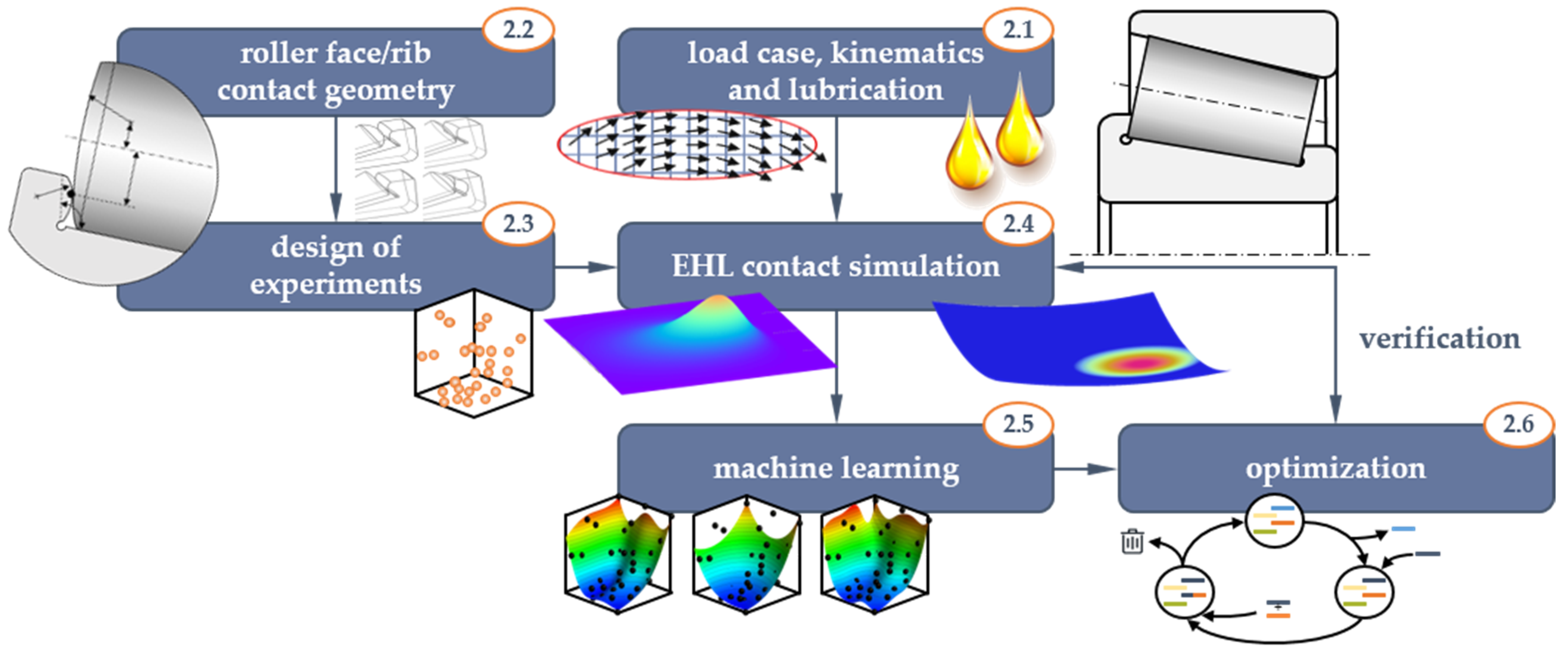
2. Materials and Methods

The general optimization procedure utilized within the scope of this contribution and as illustrated in Figure 1 has already been successfully applied to derive tailored micro-texture geometries for EHL contacts by Marian et al. [23]. Based on the geometric parameters describing the roller end face and rib geometries, they were sampled by a statistical design of experiments (DoE) and the tribological behavior was predicted by means of EHL contact simulations. Special attention has been paid to modeling the complex geometry pairings and kinematics, which exceeds most cases of classic EHL point- or line-contacts. For each of the geometric pairings considered, a database was generated on the basis of which key target variables such as coefficient of friction (COF), maximum pressure and minimal lubricant film height were approximated by a meta-model and an optimization was carried out. Finally, the predicted optima were verified again by EHL simulations. This whole process was done separately for each geometric pairing to finally compare their respective optima and derive generalized design recommendations. The relevant aspects are described in detail in the following Section 2.2, Section 2.3, Section 2.4, Section 2.5 and Section 2.6. At first, however, the parameters and properties of the TRB, load case and lubricant considered in this study are defined in Section 2.1.

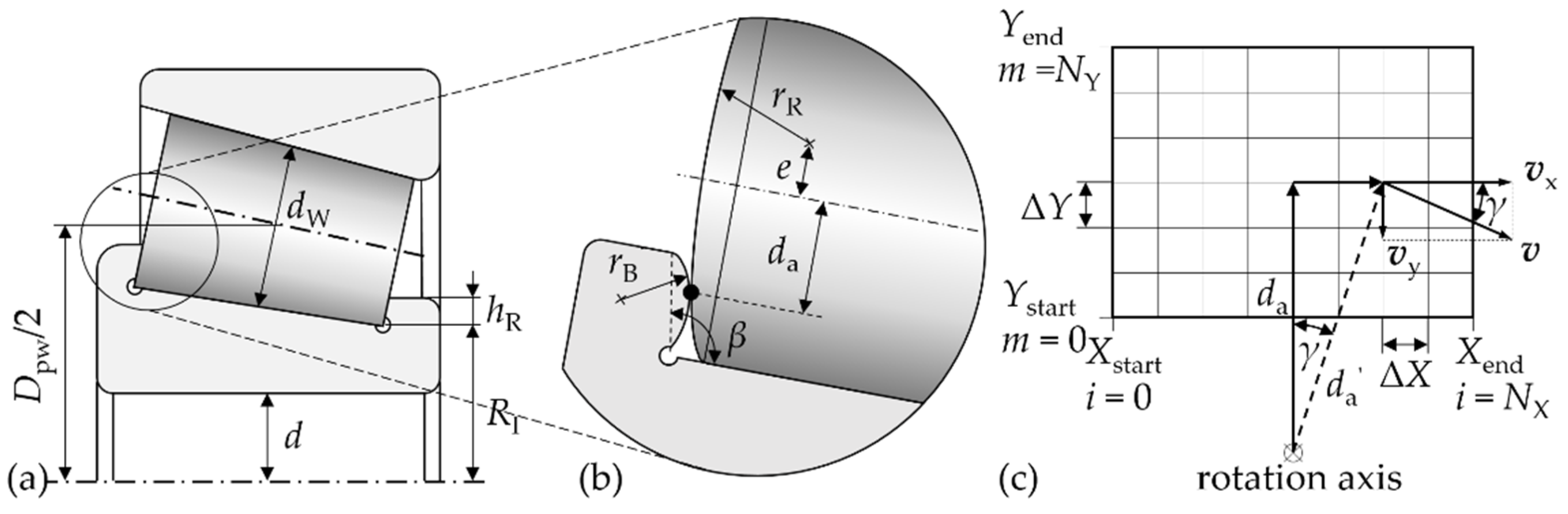
2.1. TRB Load Case, Kinematics and Lubrication

A standard TRB 30207, as illustrated in Figure 2a, with an inner ring rotational speed nI of 1000 min−1 under a pure axial load of 12 kN, to get an equal load at the rib for each roller, was studied. For the materials, typical values for rolling bearing steel (100Cr6) were considered with a Young’s modulus E of 210,000 N/mm2 and a Poisson’s ratio ν of 0.3.
The kinematics for the roller face/rib contact of the TRB (see Figure 2b) were described by a discretized velocity matrix and mapped to the surface matrix of the EHL simulation (see Section 2.4) as depicted in Figure 2c. Thereby, the velocities in x- and y-direction of both contacting bodies were calculated at each grid node. When assuming the outer ring to be stationary, the rotational speed of each roller element can be written as follows [24]:
n W = n I 2 · ( D p w 2 · d W 2 · d W · cos 2 β D p w ) ,
with the pitch diameter given by:
D p w = 2 · ( R I + d W cos β ) ,
the average diameter of the roller dW and the rib angle β. Here, the grid had lateral dimensions (Xstart, Xend, Ystart, Yend) to cover eight times the Hertzian width (see Section 2.4) and was meshed with a number of 1024 nodes each in the x- (Nx) and y-direction (Ny), which also corresponded to the EHL calculation domain. The discrete distance between the nodes was given by:
Δ X = X e n d X s t a r t N X ,   Δ Y = Y e n d Y s t a r t N Y   .
Each node was expressed by a column indexed by i in the x-direction and a row indexed by m in the y-direction. Thus, the distance da of the contact point in the middle of the grid to the rotation axis of the rolling element or the ring was derived:
d a = R I + ( h R 2 + Y e n d m · Δ Y ) · cos β .
With the angle γ resulting from the number of columns and the distance of notes in x-direction, the distance da′ to the rotation axis for each node was obtained:
d a = d R cos γ   with   γ ( i ) = tan 1 X s t a r t + Δ X · i d a .
The velocity v tangential to the axis of rotation for each node was thus determined by [24]:
v ( i ,   m ) = 2 · d a · π · n I / W ,
whereas the components of this vector in the x- and y-direction were calculated by:
v x = v · cos γ   and   v y = v · sin γ .
Thus, the velocity distribution of both, the inner ring and the rolling element, in each node could be determined. It should be noted that both have different algebraic signs and the former had larger values than the latter.
The contact was assumed to be lubricated with a sufficient amount (fully flooded) of FVA 3 reference mineral oil. The respective properties are summarized in Table 1. Pressure p dependent density ρ and viscosity η were considered following the models from Dowson and Higginson [25]:
ρ ( p ) = ρ 0 5.9 · 10 8 + 1.34 · p 5.9 · 10 8 + p
as well as Roelands [26]:
η ( p ) = η 0 · e { [ ln ( η 0 ) + 9.67 ] · [ 1 + ( 1 p p R ) z R ] } ,
respectively. Non-Newtonian rheology, i.e., shear-thinning of the fluid, was modeled by means of the Ree–Eyring approach [27]:
γ ˙ = F ( τ ) = τ 0 η · sinh ( τ τ 0 ) .

2.2. Roller Face/Rib Contact Geometry

While the geometry of the roller end face can be described by the face radius rR and the eccentricity e, the rib is characterized by the raceway/rib angle β as well as the rib radius rB, see Figure 2b.
The position of the contact point is another constraint. Therefore, the contact point lies in the middle of the rib height. The variations of the radii and the eccentricity yield the rib angle. Within this contribution, the principle pairing possibilities of sphere, cone and torus were evaluated by means of parameter variations and limitations as shown in Table 2.
Based on these parameters, the geometric pairing was transferred to the EHL simulation (Section 2.4). Before, this required further processing, for which parts of the so-called PIMP-method as introduced by Wirsching et al. [28] was applied. At first, the relative positions of the two contacting bodies and their local coordinate system within the global one were determined. The contact zone position was calculated using the position vectors q (x, y, z) and the vectors n (x, y, z) normal to the bodies’ surface in the local coordinate systems. The latter are in the same position and oriented in opposite directions. Subsequently, the geometry of each body was described analytically in the Cartesian coordinate system G. For the sphere, this was defined as:
x 2 + y 2 + z 2 = r 2 ,
for the cone as:
x 2 + y 2 m · z 2 = 0
and for the torus as:
( x 2 + y 2 + z 2 + R 2 r 2 ) 2 = 4 · R 2 · ( x 2 + y 2 ) .
The vectors q and n determined the position and orientation of the point of contact and a projection plane for each body. A ray tracing method projected the geometry on the projection planes in the Cartesian coordinate system G:
s ( t ) = q + t · n .
The two projection planes were parallel and congruent, and the contact point was located in the center. By converting above equations, a function defining the distance between the two rigid bodies to the projection plane was derived. For the case of the sphere, this can be written as follows:
g G ( x , y ) : t = ( q x n x + q y n y + q z n z ) + ( q x n x + q y n y + q z n z ) 2 ( q x 2 + q y 2 + q z 2 r 2 ) ,
where t = 0 is the point of contact and both geometries of the two bodies were described by the distance functions g1(x, y) and g2(x, y). With:
g ( x , y ) = g 1 ( x , y ) g 2 ( x , y ) ,
a substitute geometry was finally generated to equivalently describe the contact of the two rigid bodies [28]. The corresponding expressions for the cone could be written as:
g G ( x , y ) :   t = ( q x n x + q y n y m 2 q z n z ) + ( q x n x + q y n y m 2 q z n z ) 2 ( d x 2 + d y 2 d z 2 m 2 ) · ( q x 2 + q y 2 q z 2 m 2 ) ( d x 2 + d y 2 d z 2 m 2 )
and the torus:
t 4 + 4 ( q x n x + q y n y + q z n z ) t 3 + 2 [ ( q x 2 + q y 2 + q z 2 ) + 2 ( q x n x + q y n y + q z n z ) 2 + R 2 ( 1 2 n x 2 2 n y 2 ) r 2 ] t 2 + 4 [ ( q x 2 + q y 2 + q z 2 ) ( q x n x + q y n y + q z n z ) + R 2 ( q x n x q y n y + q z n z ) r 2 ( q x n x + q y n y + q z n z ) ] t + [ ( q x 2 + q y 2 + q z 2 ) + R 2 r 2 ] 2 4 R 2 ( q x 2 + q y 2 ) = 0
respectively.

2.3. Design of Experiments

In order to generate a sufficient database for the deduction of correlations between input and target variables with a minimum of computational effort, methods of statistical DoE can be applied. Here, a so-called latin hypercube sampling (LHS) from the group of uniformly distributed test field was used, since this is particularly suitable for generating a wide range of approximation or meta-models (see Section 2.5). Thereby, the trial points are partitioned in such a way that they fill the design space as uniformly as possible and provide information about almost every area with little computational effort. The LHS elements are created by subtracting a random number between zero and one from each element of a matrix with columns consisting of random permutations of the numbers {1, …, nf}, with nf being the number of input factors, and then dividing this value by the number of trial points np. For this, the Statistics and Machine Learning toolbox of MATLAB (The Mathworks Inc., Natick, MA, USA) was utilized to obtain LHS designs optimized regarding the distances of the trial points by means of the Maximin criterion [29,30]. The number of trial points was chosen as 20 for nf = 1, 50 for nf = 2 and 100 for nf = 3, see Table 2. The concave geometry pairings had the additional constraint, that the absolute value of the rib radius rB had to be larger than the roller face radius rR. Therefore, the number of trial points was doubled and the points outside the constraint were deleted.

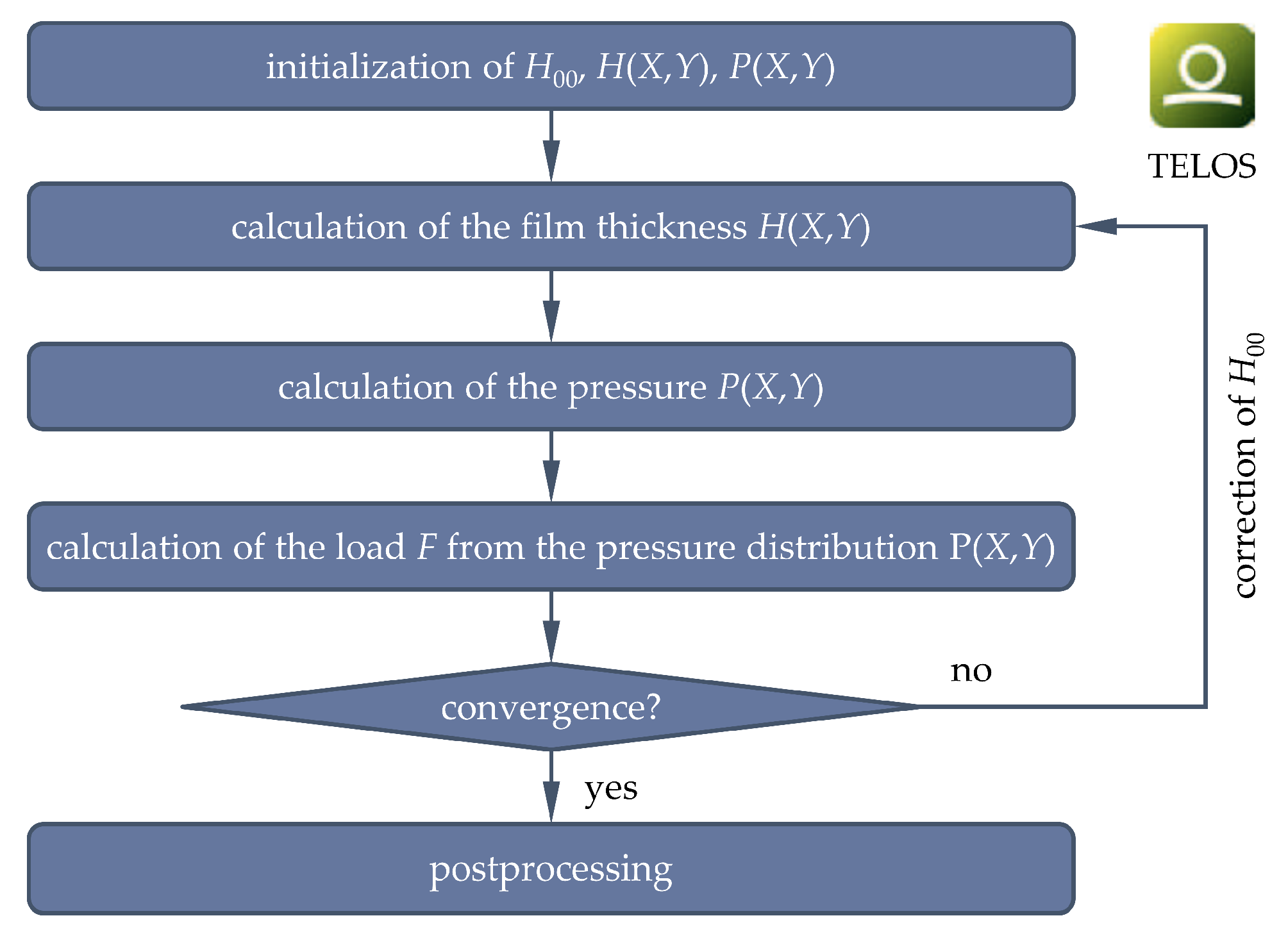
2.4. EHL Contact Simulation

Numerical EHL modeling is usually done by a coupled solution of the lubricant’s hydrodynamics and the elastic deformation of the contacting bodies. For this purpose, the software tool TELOS 5.0 (Schaeffler Technologies AG & Co. KG, Herzogenaurach, Germany) was used for a quasi-static, isothermal, lubricated contact simulation with a non-Newtonian rheology model. For a better conditioning and stabilized solution of the system of equations, which are briefly introduced below, the coordinates x and y, the lubricant gap h, the hydrodynamic pressure p as well as viscosity η and density ρ were normalized with the Hertzian contact widths a’, the Hertzian approach of both bodies c’, the maximal Hertzian pressure p0 as well as the ambient viscosity η0 and density ρ0:
X = x a ,   Y = y a ,   H = h c ,   P = p p 0 ,   η ¯ = η η 0 ,   ρ ¯ = ρ ρ 0 ,
Due to the geometries differing strongly from classical point contacts, the normalization was done using the values of a ball-on-plane pairing with a ball diameter of 100 mm.
The geometry was described by the lubricant gap equation taking into account the distance of the rigid bodies H00, the approximated undeformed geometry of the respective pairing G(X, Y) as well as the combined elastic deformation:
H ( X , Y ) = H 00 + G ( X , Y ) + 2 π · E · Ω   P ( X , Y ) ( X X ) 2 + ( Y Y ) 2 d X d Y .
The calculation of the elastic contact was based on a variational principle [31]. Here, the pressure distribution and the actual contact zone minimized the absolute complementary distortion energy. An iterative algorithm following Polonsky and Keer [32] was used to solve the contact problem described here. This was based on the conjugate gradient method and the fast Fourier transformation, allowing a stable and efficient solution. The quasi-stationary Reynolds differential equation was applied to account for the fluid flow and hydrodynamic pressure generation:
X ( ρ ¯ H 3 η ¯ P X ) + Y ( ρ ¯ H 3 η ¯ P Y ) = 6 · ( u 1 + u 2 ) · ( ρ ¯ H ) X + 6 · ( v 1 + v 2 ) · ( ρ ¯ H ) Y .
Here, the sum velocities u1,2 and v1,2 in x- and y-direction mapped the motion of the contacting bodies (see Section 2.1). Non-Newtonian effects were considered according to the rheology model of Ree-Eyring:
u X = τ x y η ¯ · F ( τ )   with   F ( τ ) 1 .
Furthermore, the following boundary conditions were assumed:
P ( X ,   Y ) = 0 ;   ( X , Y ) d Ω ;   here   d Ω   denoted   the   edges   of   the   domain
P ( X ,   Y ) 0 ;   ( X , Y ) Ω ,   Ω   denoted   all   points   in   the   comupational   space
The equilibrium between normal load F and the hydrodynamic pressure was ensured by the load balance equation:
F =   Ω   P ( X , Y ) d X d Y .
The whole system of equations was solved iteratively based upon the finite difference method as well as the elastic half-space theory while applying multigrid methods and fast Fourier transformation as well as relaxation for numerical damping and stabilization [33]. The discretization of the domain was controlled stepwise with a binary system from 64 to 2048 points and the size of the calculation domain was chosen to be rectangular with lateral dimensions of eight times the Hertzian contact width a’. The numerical solution scheme is shown in Figure 3 and for more numerical details, the interested reader is referred to [34,35,36]. After the converged calculation, the COF was calculated:
C O F = Ω τ x y   d X d Y F .

2.5. Machine Learning

Based on the simulation results of the DoE introduced in Section 2.3, the tribological behavior can be described by approximation- or meta-models [38,39]. Thus, the effect of the different factor combinations in the form of geometric parameters on the target variables (pressure, fluid film height, COF) can be determined and an optimization can be performed in a computationally efficient way. The meta-model, a representation of the simulation results, may be based on different approaches. One of the most elementary forms is polynomial regression, where an unknown function is approximated by a polynomial solution of usually low degree [29,40]. An extension with local character based on local weighting functions is the method of moving least squares (MLS) [41]. Usually, linear or quadratic terms are utilized for the base function. Furthermore, the Kriging model, also known as Gaussian process regression, is an accurate surrogate model due to its flexibility in approximating different and complex response functions by interpolating the data points and providing a confidence interval of the prediction [42]. The assessment of the prediction quality of the respective approach represents a central aspect of meta-modeling. An automated optimization was enabled by a so-called Meta-model of Optimal Prognosis (MOP). The concept developed by Most and Will [40,43] builds upon a two-step elimination process of non-significant variables based on a coefficient of determination (COD) and importance (COI) as well as the automatic selection of the most suitable of aforementioned approximations based on a coefficient of prognosis (COP). The latter is advantageous due to its automatic scaling to values between 0 and 1. For example, a COP of 0.9 corresponds to a prediction quality of 90% for new data points. Here, the initial data set was split into training and test data with a ratio of 70/30 in such a way that the response ranges in the data sets displayed maximum conformity to the overall data set. The MOP was implemented in the software OptiSlang version 8.1.0 (Dynardo GmbH, Weimar, Germany).

2.6. Optimization

For the determination of global optima of the geometric parameters based upon the MOP, various algorithms can be utilized. Basically, there are gradient-based methods [44], response surface methods (RSM) [45] and methods inspired by nature, such as particle swarm optimization (PSO) [46] or evolutionary/genetic algorithms (EA/GA) [47]. The latter were used within the scope of this study since they are an efficient and flexible way to optimize unknown problems and were also implemented in the software OptiSlang. Thereby, a population of solution candidates for the optimization problem was simulated in a selection process with underlying evolutionary principles. At first, the initial individuals were evaluated with respect to the optimization goals, which defined subsequent mating selection and the generation of child individuals from each parent. The new generation was created by recombining the characteristics of the parent individuals as well as a mutation and integrated into the existing population under environmental selection, replacing parent individuals. After each cycle, the termination conditions in form of a maximum number of iterations and a quality stagnation for a defined number of generations were checked. The EA setting underlying this contribution is summarized in Table 3.

3. Results

In the following, sample results of the EHL simulations are shown in Section 3.1, followed by the results of meta-modeling in Section 3.3, optimization in Section 3.3 as well as verification in Section 3.4.

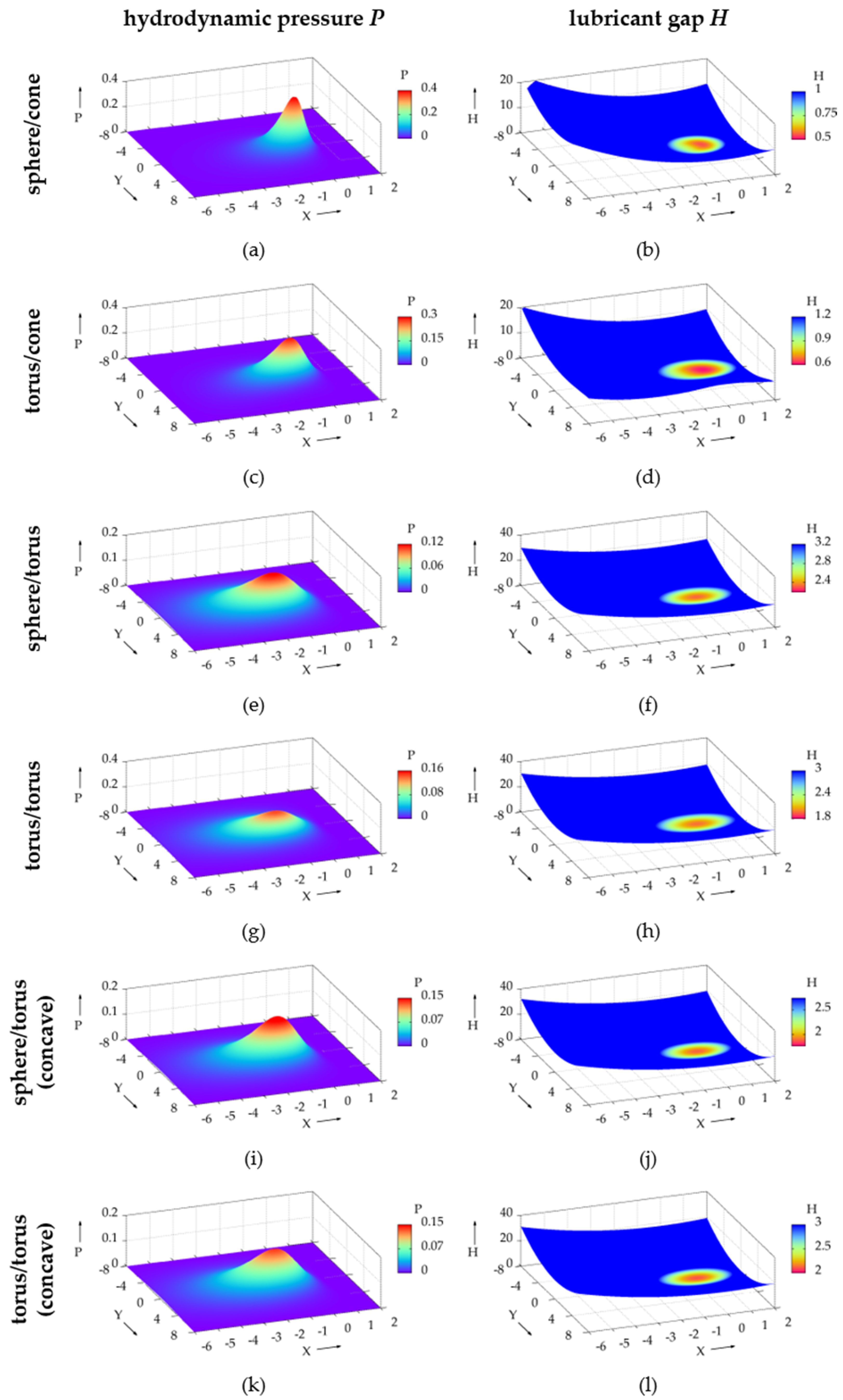
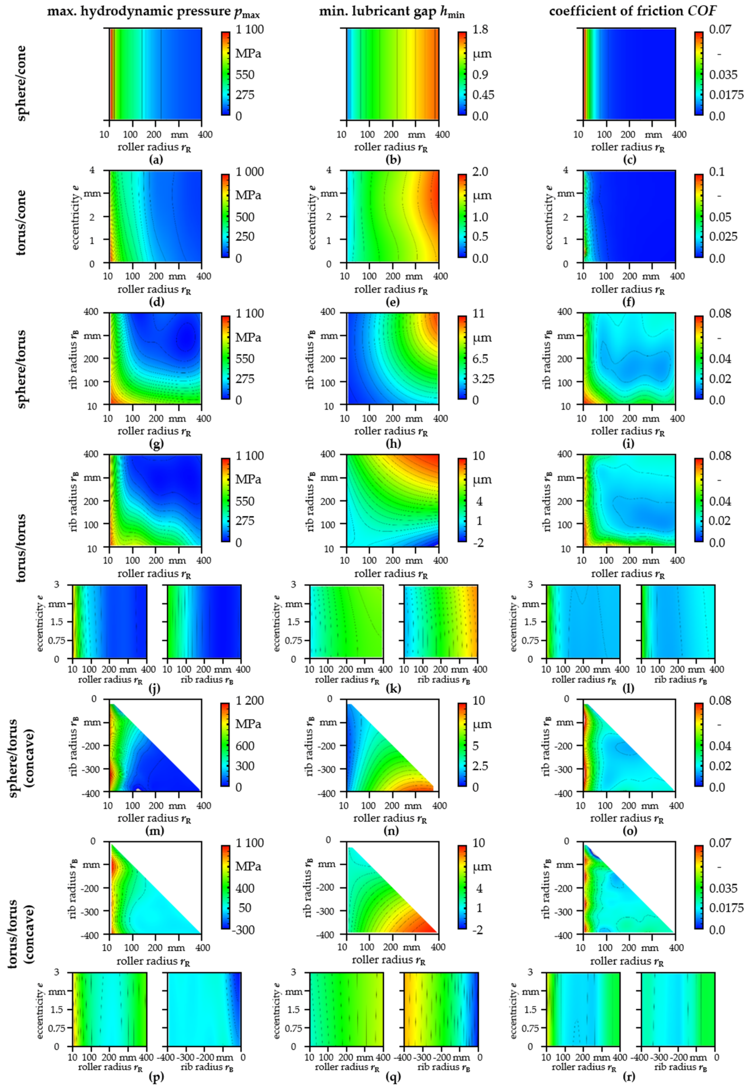
3.1. Pressure, Film Thickness and Friction

The calculated pressure and lubricant gap distributions of one representative parameter set near the center of the parameter field for each pairing (see Table 4) are illustrated in Figure 4a–l). The main direction of motion of the rolling element and inner ring and thus the main fluid flow was in the x-direction. Accordingly, the pressure in the contact inlet increased and reached a maximum in the contact center before dropping again at the contact outlet. No pronounced Petrusevich spike was observed. Correspondingly, there was an elastic flattening in the contact center as well as a minimum in the lubricant film height with a slight horseshoe-shape near the contact outlet. In the y-direction, the distributions were nearly axisymmetric with small form deviations due to the variation in flow velocities.
For all geometric pairings, a different degree of ellipticity of the elastically deformed contact area with the longer semi-axis in the x-direction was found. This was less distinct for the sphere/cone and torus/cone pairings, but strongly pronounced for the sphere/torus and torus/torus pairings. Moreover, there were considerable differences in the magnitudes of the pressure maxima and the lubricant film heights between the different geometry pairings, see Table 4. In particular, the sphere/cone and torus/cone pairings exhibited larger pressures due to smaller elastically deformed contact areas while the sphere/torus and torus/torus geometries resulted in higher lubricant gaps. Accordingly, differences in the COF were observed. It was noticeable that the sphere/cone and torus/cone pairings featured rather low COFs and the sphere/torus and torus/torus geometries exhibited higher levels.

3.2. Influence of the Roller Face/Rib Geometry

In the following, the effects of the various geometric parameters on friction as well as the lubricant gap as an indicator of potential wear and the maximum hydrodynamic pressure will be shown. The results from the EHL simulations from the LHS are provided in the Supplementary Material and the calculated response surfaces of the MOP are displayed in Figure 5a–r).
Generally, red color indicates higher and blue color lower values of studied variables. The maximum hydrodynamic pressure and the COF were most accurately approximated by anisotropic kriging except for the pairing sphere/cone, where MLS was used for the pressure and linear regression for the COF. MLS was also applied for minimum lubricant gap of the sphere/cone pairing. The lubricant gap of all other pairings was represented by linear regression. The corresponding COPs are listed in Table 5.
For the sphere/cone geometry (Figure 5a–c), the maximum hydrodynamic pressure, the minimum lubricant gap and the COF only depended on the face radius rR as single geometrical variable. Apparently, a smaller radius resulted in higher pressure and COFs as well as smaller lubricant gaps and vice versa. The same behavior was basically also observed for the torus/cone (Figure 5d–f), sphere/torus concave (m–o) and torus/torus concave (p–r) pairings. Furthermore, the eccentricity e of roller radius had a rather small or no influence on calculated results (Figure 5d–f,j–l,p–r) since the response surfaces barely changed in the eccentricity direction. Moreover, for all geometries, lower maximum pressures and larger lubricant gaps were achieved for larger radii rB and rR. However, the lowest COFs were partly obtained within the studied parameter field, see Figure 5i,l,o,r).

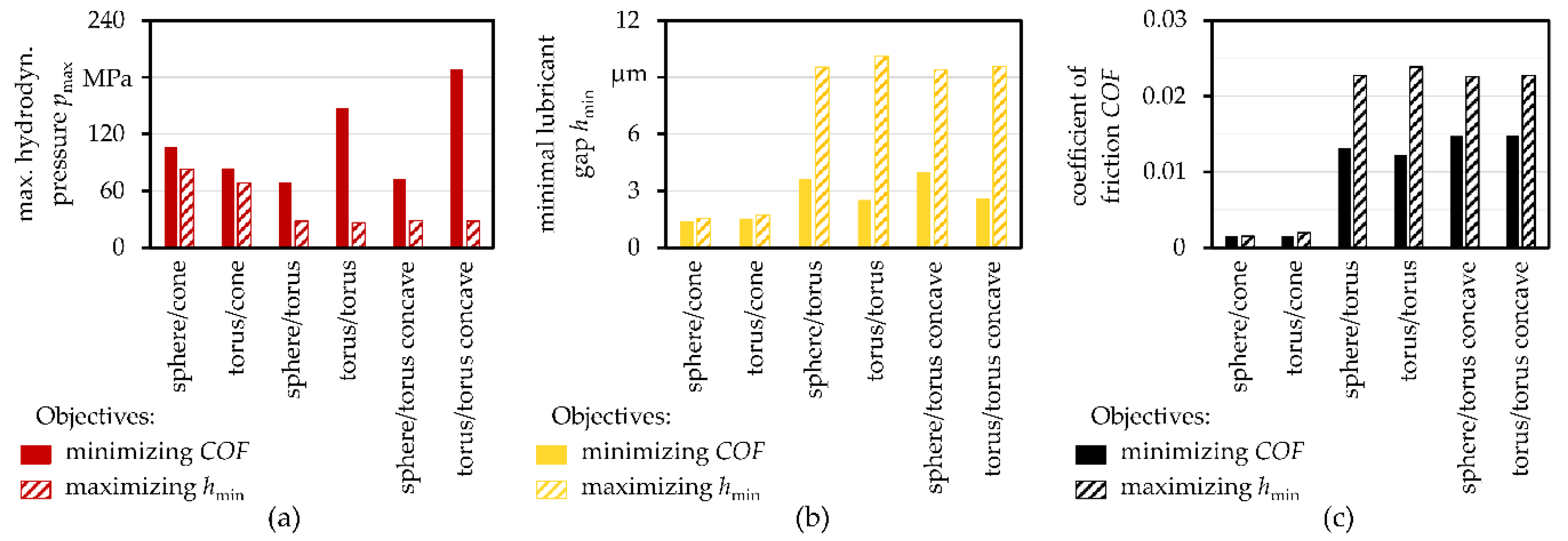
3.3. Optimization of the Roller Face/Rib Geometry

Multi-objective optimization by means of the EA was performed based upon the MOP response surfaces in order to minimize the COFs or maximize the minimum lubricant gap. This led to a Pareto front of which the extrema in the respect to the optimization goals (lowest friction or highest film height) are summarized in Figure 6. The resulting maximum pressure, minimum film height and COF are illustrated in Figure 6a–c). It can be seen that both objectives led to contradicting results since the lowest friction (sphere/cone and torus/cone geometry in Figure 6c) also resulted in rather small lubricant gaps (sphere/cone and torus/cone geometry in Figure 6b) while higher lubricant gaps also led to higher COFs. The hydrodynamic pressure behaved similar to the minimal lubricant gap and thinner lubricant gaps resulted in higher hydrodynamic pressures. Generally, toroidal rib geometries generated lower hydrodynamic pressures. Accordingly, the optimized geometry parameters in Table 6 differed in dependency of the objective. When targeting a higher minimum film height, the optima were found near the extrema of the studied parameter field (largest possible radii) while the optima were found rather in the middle of the rib radius and the roller face radius field for the pairings torus/torus, sphere/torus concave and torus/torus concave when minimizing friction.

3.4. Verification of Optimized Roller Face/Rib Geometry

Finally, the optimization results based upon the MOP/EA were verified. Therefore, the parameter combinations from the optimization for each geometry pairing (Table 6) were recalculated by means of EHL contact simulations. The maximum hydrodynamic pressure, the minimum lubricant gap and the COF were compared to the prediction from the MOP/EA, see Table 7. Thereby, rather small deviations between the prediction and the EHL simulation for most variables and geometry combinations occurred. The minimum lubricant film height and COF in particular were excellently predicted with errors below 2%. Only the accuracy of the hydrodynamic pressure for the sphere/torus, torus/torus concave after minimizing the COF as well as for sphere/torus and torus/torus when maximizing the lubricant gap showed larger discrepancies.

4. Discussion

4.1. Load Carrying Capracity Versus Friction—Influences of the Geometries

The roller face/rib contact was characterized by rather moderate loads and high sliding speeds. Hence, pressure and lubricant gap distribution (Figure 4) showed typical characteristics for EHL contacts operating under such conditions [48] and similarities to other studies on that contact reported in literature [16,17,21]. As a result of the velocity differences between the two bodies, there were also considerable frictional losses depending on the respective geometry pairings (Figure 5). Generally, larger radii tended to result in wider contact areas and thus also in higher fluid film heights as well as lower pressures required to carry the load. Correspondingly, larger radii exhibited a bigger load-bearing capacity, i.e., better protection against potential solid asperity contact and wear. However, these did not necessarily lead to lower COFs due to more fluid being sheared within the wider contact areas. In this respect, the findings corresponded well to the experimental studies from Korrenn [11]. Going beyond other studies [11,16,17,21], it was shown that, in addition to the radii, the basic geometric pairings also had a major influence on the tribological properties in terms of load-bearing capacity and frictional losses. This can be attributed to differences in the shapes and sizes of the contact areas as well as the velocity distributions, which is also substantiated by the experimental investigations from Jamison et al. [10]. Nevertheless, there remains a certain trade-off between high load carrying capacity and low friction (see Figure 6b,c). Thereby, spherical or toroidal geometries on the roller end face featuring a large radius paired with a tapered (cone) rib geometry without curvature were found to be advantageous in terms of low friction losses. For larger lubricant film heights to separate surface asperities or to support higher loads, however, spherical or toroidal roller on toroidal rib geometries with radii in the center of the analyzed parameter range were favorable (Table 6). Similar to [16,17], favorable ratios of the radii were withing the range of 0.8–0.9 for concave geometries. However, advantageous ratios were substantially larger for convex geometry pairings (~1–2) or not available after all due to one contacting partner having an uncurved surface, especially when optimizing for minimum friction.

4.2. Applicability and Limitations

Within the scope of this contribution, one TRB type, lubricant and load case with pure axial load were investigated. The conclusions are mainly valid in this respect. Changes in the boundary conditions may lead to an alteration or shift of presented results. For example, radial loads lead to the formation of a load zone and thus to variable forces and speeds for each individual roller end face/rib EHL contact during one revolution of the bearing, which would demand for time-transient calculation. In addition, the influences of the load carrying capacity of the secondary roller end face/rib contact on the behavior of the primary roller/raceway contacts were not further considered. For additional quantitative prediction accuracy regarding the frictional behavior, which would allow a comparison with corresponding experimental data, a more detailed characterization of the rheological fluid behavior as well as an adaptation of the used models might be essential [49]. Furthermore, as for most numerical EHL studies, the underlying simulations for this investigation were subject to certain assumptions (regarding the applicability of the Reynolds equation, fully flooded conditions, linear elastic material behavior etc.), which, however, can be considered to be relatively well satisfied for the studied contact. Surface roughness and thermal effects might have an influence on the tribological behavior. Taking them into account, however, also increases computational costs, which is why they were neglected considering the large number of calculations performed within the DoE. Therefore, we consider the implications to be conclusive and to have universalizability.

4.3. Prediction Capability of the ML Approach

For most geometries and objectives, the adopted ML approach based upon the MOP provided a very good prognosis, which was reflected in the high COP values mostly above 90% (Table 5) as well as the small deviations of the optimization based upon MOP/EA compared to EHL verification calculations mainly below 2% (Table 7). This indicated the possession of a sufficient database as well as the quality of the meta-models automatically selected by the MOP. Only torus rib geometries yielded somewhat larger errors, especially for very small rib radii, which can be attributed to instabilities in the EHL simulations (non-converged solutions) and thus in the underlying database in that region. However, these areas were not pertinent for the optimization regarding friction or load carrying capacity, which is why the good prediction quality in most other areas prevailed. The approach to predict and optimize the tribological behavior with the chosen approach consisting of MOP and EA can thus be evaluated as suitable. This does not have to be limited to the macro-geometry of the roller end face/rib EHL contact but can also be applied to its micro-geometry, e.g., for tailoring roughness, grinding patterns or surface textures, or to other EHL contacts.

5. Conclusions

The tribological behavior of the roller end/face rib contact of tapered roller bearings as a function of different macro-geometries was investigated within the scope of this contribution. Therefore, geometric parameters describing the roller end face and rib geometries were sampled by a statistical design of experiments. The tribological behavior was predicted by means of EHL contact simulations taking into account the complex geometry pairings and kinematics. For each of the geometric pairings considered (sphere/cone, torus/cone, sphere/torus, torus/torus, sphere/torus concave and torus/torus concave), a database was generated. Key target variables such as COF, maximum pressure and minimal lubricant film height were approximated by a meta-model of optimal prognosis and optimization was carried out using a genetic algorithm. Finally, the predicted optima were verified again by EHL simulations. For the studied load case, contact conditions and geometries, the following conclusions could be drawn:
  • The introduced machine learning approach featured excellent prediction quality and was able to efficiently and effectively support geometry optimization of EHL contacts with respect to the tribological behavior.
  • The tribological behavior of the roller end face/rib contact is mainly determined by the basic geometric pairing and the radii; eccentricity is of subordinate role.
  • There is a certain trade-off between high load carrying capacity and low frictional losses.
  • If the bearing is subjected to rather low axial loads and/or higher velocities, i.e., there is moderate risk of mixed lubrication and wear, but energy losses are to be minimized, spherical or toroidal geometries on the roller end face featuring a large radius paired with a tapered (cone) rib geometry without curvature are favorable.
  • If the bearing expects higher demands regarding axial load carrying capacity and/or lower speeds, spherical or toroidal roller on toroidal rib geometries with radii in the center of the analyzed parameter range are advantageous.

Supplementary Materials

The following are available online at https://0-www-mdpi-com.brum.beds.ac.uk/article/10.3390/lubricants9070067/s1, LHS databases from EHL simulations.

Author Contributions

Conceptualization, S.W. (Sven Wirsching) and M.M.; methodology, S.W. (Sven Wirsching) and M.M.; software, S.W. (Sven Wirsching); formal analysis, S.W. (Sven Wirsching) and M.M.; investigation, S.W. (Sven Wirsching); resources, T.S. and S.W. (Sandro Wartzack); data curation, S.W. (Sven Wirsching); writing—original draft preparation, S.W. (Sven Wirsching) and M.M.; writing—review and editing, M.M., M.B., T.S. and S.W. (Sandro Wartzack); visualization, S.W. (Sven Wirsching) and M.M.; supervision, M.M., M.B., T.S. and S.W. (Sandro Wartzack); project administration, S.W. (Sven Wirsching), M.B., T.S. and S.W. (Sandro Wartzack). All authors have read and agreed to the published version of the manuscript.

Funding

This research was funded by Schaeffler Technologies AG & Co. KG.

Institutional Review Board Statement

Not applicable.

Informed Consent Statement

Not applicable.

Data Availability Statement

The data presented in this study are available on request from the corresponding author.

Acknowledgments

The authors greatly acknowledge Schaeffler Technologies AG & Co. KG for funding the project, the permission to utilize the Telos software and to publish the results.

Conflicts of Interest

The authors declare no conflict of interest.

Nomenclature

aHertzian contact width in x-direction
bHertzian contact width in y-direction
cHertzian contact approach in z-direction
CODcoefficient of determination
COFcoefficient of friction
COIcoefficient of importance
COPcoefficient of prognosis
dinner ring bore diameter
dacontact point distance
dadistance to rotation axis
dWrolling element diameter
Dpwpitch diameter
eeccentricity
EYoung’s modulus
Fnormal load
gidistance function
Gundeformed geometry profile
hlubricant gap
hRrib height
Hnormalized lubricant gap
icolumn index
mrow index
mslope of the cone
nIinner ring speed
nfnumber of input faktors
nWrolling element speed
n normal vector
Ninumber of nodes
phydrodynamic pressure
pRreference hydrodynamic pressure
Pnormalized hydrodynamic pressure
q position vector
rradius
rBrib radius
rRroller end face radius
Rtorus radius
RIinner ring raceway radius
s projection vector
tdistance to projection plane
uisliding velocity
vtangential sliding velocity
visliding velocity
x, y, zcartesian coordinates
X, Y, Z
zRRoelands exponent
αppressure-viscosity coefficient
βrib angle
βVvolume expansion coefficient
γangle from rotational axis
γLpressure limiting shear stress
γ ˙ shear rate
Δ X ,   Δ Y
ηfluid viscosity
η0base viscosity
η ¯ normalized fluid viscosity
νPoisson’s ratio
ρfluid density
ρ0base density
ρ ¯ normalized fluid density
τshear stress
τ0equivalent shear stress
τLlimiting shear stress
Ωcontact domain

References

  1. Tong, V.-C.; Hong, S.-W. Characteristics of tapered roller bearing subjected to combined radial and moment loads. Int. J. Precis. Eng. Manuf. Green Technol. 2014, 1, 323–328. [Google Scholar] [CrossRef] [Green Version]
  2. Dragoni, E. Optimal design of tapered roller bearings for maximum rating life under combined loads. Mech. Ind. 2017, 18, 112. [Google Scholar] [CrossRef] [Green Version]
  3. Lostado, R.; Escribano García, R.; Fernandez Martinez, R. Optimization of operating conditions for a double-row tapered roller bearing. Int. J. Mech. Mater. Des. 2016, 12, 353–373. [Google Scholar] [CrossRef]
  4. Dean, S.W.; Cowles, J.H.; Houle, C.A. Roller Profile Development for an Axially Loaded, Single Row Spherical Roller Bearing in an Oscillating Application. J. ASTM Int. 2012, 9, 103891. [Google Scholar] [CrossRef]
  5. Wang, Z.W.; Meng, L.Q.; Hao, W.S.; Zhang, E. Finite Element Method Analysis and Optimal Design of Roller Convexity of Tapered Roller Bearing. AMR 2010, 139–141, 1079–1083. [Google Scholar] [CrossRef]
  6. Lostado-Lorza, R.; Escribano-Garcia, R.; Fernandez-Martinez, R.; Illera-cueva, M.; Mac Donald, B.J. Using the finite element method and data mining techniques as an alternative method to determine the maximum load capacity in tapered roller bearings. J. Appl. Log. 2017, 24, 4–14. [Google Scholar] [CrossRef]
  7. Kalyan, M.; Tiwari, R.; Ahmad, M.S. Multi-objective optimization in geometric design of tapered roller bearings based on fatigue, wear and thermal considerations through genetic algorithms. Sādhanā 2020, 45. [Google Scholar] [CrossRef]
  8. Tiwari, R.; Sunil, K.K.; Reddy, R.S. An Optimal Design Methodology of Tapered Roller Bearings Using Genetic Algorithms. Int. J. Comput. Methods Eng. Sci. Mech. 2012, 13, 108–127. [Google Scholar] [CrossRef]
  9. Jurko, J.; Panda, A.; Valíček, J.; Harničárová, M.; Pandová, I. Study on cone roller bearing surface roughness improvement and the effect of surface roughness on tapered roller bearing service life. Int. J. Adv. Manuf. Technol. 2016, 82, 1099–1106. [Google Scholar] [CrossRef]
  10. Jamison, W.E.; Kauzlarich, J.J.; Mochel, E.V. Geometric Effects on the Rib-Roller Contact in Tapered Roller Bearings. AsLE Trans. 1977, 20, 79–88. [Google Scholar] [CrossRef]
  11. Korrenn, H. Gleitreibung und Grenzbelastung an den Bordflächen von Kegelrollenlagern Einfluß von Drehzahl, Belastung, Schmierstoff und Gestaltung der Gleitflächen nach Versuch und Berechnung; VDI-Verl.: Düsseldorf, Germany, 1967; ISBN 0341-1648. [Google Scholar]
  12. Tong, V.-C.; Hong, S.-W. Optimization of partially crowned roller profiles for tapered roller bearings. J. Mech. Sci. Technol. 2017, 31, 641–650. [Google Scholar] [CrossRef]
  13. Porras-Vazquez, A.; Fillot, N.; Vergne, P.; Philippon, D.; Morales-Espejel, G.E. Influence of spin on film thickness in elastohydrodynamic starved point contacts. Tribol. Int. 2021, 156, 106825. [Google Scholar] [CrossRef]
  14. Dormois, H.; Fillot, N.; Vergne, P.; Dalmaz, G.; Querry, M.; Ioannides, E.; Morales-Espejel, G.E. First Traction Results of High Spinning Large-Size Circular EHD Contacts from a New Test Rig: Tribogyr. Tribol. Trans. 2009, 52, 171–179. [Google Scholar] [CrossRef]
  15. Zhang, Z.; Qiu, X.; Hong, Y. EHL Analysis of Rib-Roller End Contact in Tapered Roller Bearings. Tribol. Trans. 1988, 31, 461–467. [Google Scholar] [CrossRef]
  16. Gadallah, N.; Dalmaz, G. Hydrodynamic Lubrication of the Rib-Roller End Contact of a Tapered Roller Bearing. J. Tribol. Trans. ASME 1984, 106, 265–272. [Google Scholar] [CrossRef]
  17. Wang, W.; Wong, P.L.; Zhang, Z. Partial EHL analysis of rib-roller end contact in tapered roller bearings. Tribol. Int. 1996, 29, 313–321. [Google Scholar] [CrossRef]
  18. Patir, N.; Cheng, H.S. An Average Flow Model for Determining Effects of Three-Dimensional Roughness on Partial Hydrodynamic Lubrication. J. Lubr. Technol. 1978, 100, 12–17. [Google Scholar] [CrossRef]
  19. Greenwood, J.A.; Tripp, J.H. The Contact of Two Nominally Flat Rough Surfaces. Proc. Inst. Mech. Eng. 1970, 185, 625–633. [Google Scholar] [CrossRef]
  20. Colin, F.; Chevalier, F.; Chaomleffel, J.-P.; Dalmaz, G.; de Mul, J. Starved Elastohydrodynamic Lubrication of the Rib-Roller End Contact in Tapered Roller Bearings: Film Thickness, Traction and Moments. In Tribology for Energy Conservation, Proceedings of the 24th Leeds-Lyon Symposium on Tribology, London, UK, 4–6 September 1997; Elsevier: Amsterdam, The Netherlands, 1998; pp. 253–263. ISBN 9780444500335. [Google Scholar]
  21. Fujiwara, H.; Tsujimoto, T.; Yamauchi, K. Optimized Radius of Roller Large End Face in Tapered Roller Bearings(Machine Elements, Design and Manufacturing). JSMET 2009, 75, 2319–2326. [Google Scholar] [CrossRef] [Green Version]
  22. Rosenkranz, A.; Marian, M.; Profito, F.J.; Aragon, N.; Shah, R. The Use of Artificial Intelligence in Tribology—A Perspective. Lubricants 2021, 9, 2. [Google Scholar] [CrossRef]
  23. Marian, M.; Grützmacher, P.; Rosenkranz, A.; Tremmel, S.; Mücklich, F.; Wartzack, S. Designing surface textures for EHL point-contacts—Transient 3D simulations, meta-modeling and experimental validation. Tribol. Int. 2019, 137, 152–163. [Google Scholar] [CrossRef]
  24. Harris, T.A.; Kotzalas, M.N. Rolling Bearing Analysis; CRC—Taylor & Francis: Boca Raton, FL, USA, 2007; ISBN 9780849381676. [Google Scholar]
  25. Dowson, D.; Higginson, G.R.; Hopkins, D.W. Elasto-Hydrodynamic Lubrication: International Series on Materials Science and Technology; Elsevier Science: Burlington, MA, USA, 2014; ISBN 9781483181899. [Google Scholar]
  26. Roelands, C. Correlational Aspects of the Viscosity-Temperature-Pressure Relationship of Lubricating Oils. Ph.D. Thesis, Delft University of Technology, Delft, The Netherlands, 1966. [Google Scholar]
  27. Ree, F.; Ree, T.; Eyring, H. Relaxation Theory of Transport Problems in Condensed Systems. Ind. Eng. Chem. 1958, 50, 1036–1040. [Google Scholar] [CrossRef]
  28. Wirsching, S.; Schwarz, S.; Tremmel, S. Use of analytically describable geometries to calculate the contact between rolling element face and rib in bearing simulations. Tribol. Und. Schmier. 2020, 67, 25–33. [Google Scholar] [CrossRef]
  29. Siebertz, K.; van Bebber, D.; Hochkirchen, T. Statistische Versuchsplanung: Design of Experiments (DoE); Springer: Berlin, Germany, 2010; ISBN 978-3-642-05493-8. [Google Scholar]
  30. Johnson, M.E.; Moore, L.M.; Ylvisaker, D. Minimax and maximin distance designs. J. Stat. Plan. Inference 1990, 26, 131–148. [Google Scholar] [CrossRef]
  31. Kalker, J.J. Variational Principles of Contact Elastostatics. IMA J. Appl. Math. 1977, 20, 199–219. [Google Scholar] [CrossRef]
  32. Polonsky, I.A.; Keer, L.M. A numerical method for solving rough contact problems based on the multi-level multi-summation and conjugate gradient techniques. Wear 1999, 231, 206–219. [Google Scholar] [CrossRef]
  33. Lubrecht, A.A. The Numerical Solution of the Elastohydrodynamically Lubricated Line- and Point Contact Problem, Using Multigrid Techniques. Ph.D. Thesis, University of Twente, Enschede, The Netherlands, 1987. [Google Scholar]
  34. Wijnant, Y.H. Contact Dynamics in the Field of Elastohydrodynamic Lubrication. Ph.D. Thesis, University of Twente, Enschede, The Netherlands, 1998. [Google Scholar]
  35. Venner, C.H.; Lubrecht, A.A. Multilevel Methods in Lubrication, 1st ed.; Elsevier: Amsterdam, The Netherlands, 2000; ISBN 0-444-50503-2. [Google Scholar]
  36. Venner, C.H. Multilevel Solution of the EHL Line and Point Contact Problems. Ph.D. Thesis, University of Twente, Enschede, The Netherlands, 1991. [Google Scholar]
  37. Pausch, M. Untersuchung des Einflusses von Definiert Gefertigten Mikrostrukturen auf Schmierfilmbildung und Kontaktpressung in Hoch Belasteten Wälzkontakten; VDI-Verlag: Dusseldorf, Germany, 2013. [Google Scholar]
  38. Booker, A.J.; Dennis, J.E.; Frank, P.D.; Serafini, D.B.; Torczon, V.; Trosset, M.W. A rigorous framework for optimization of expensive functions by surrogates. Struct. Optim. 1999, 17, 1–13. [Google Scholar] [CrossRef]
  39. Simpson, T.W.; Poplinski, J.D.; Koch, P.N.; Allen, J.K. Metamodels for Computer-based Engineering Design: Survey and recommendations. EWC 2001, 17, 129–150. [Google Scholar] [CrossRef] [Green Version]
  40. Most, T.; Will, J. Metamodel of Optimal Prognosis—An automatic approach for variable reduction and optimal meta-model selection. Weimarer Optim. Stochastiktage 2008, 5, 20–21. [Google Scholar] [CrossRef]
  41. Lancaster, P.; Salkauskas, K. Surfaces Generated by Moving Least Squares Methods. Math. Comput. 1981, 37, 141. [Google Scholar] [CrossRef]
  42. Martin, J.D.; Simpson, T.W. Use of Kriging Models to Approximate Deterministic Computer Models. AIAA J. 2005, 43, 853–863. [Google Scholar] [CrossRef]
  43. Most, T.; Will, J. Recent advances in Meta-model of Optimal Prognosis. Proc. Weimarer Optim. Stochastiktage 2010, 7, 21–22. [Google Scholar]
  44. Nocedal, J.; Wright, S.J. Numerical Optimization; Springer: New York, NY, USA, 2006; ISBN 978-0-387-30303-1. [Google Scholar]
  45. Box, G.E.P.; Draper, N.R. Response Surfaces, Mixtures, and Ridge Analyses, 2nd ed.; John Wiley & Sons: New York, NY, USA, 2007; ISBN 978-0-470-05357-7. [Google Scholar]
  46. Eberhart, R.; Kennedy, J. A new optimizer using particle swarm theory. In MHS’95. Proceedings of the Sixth International Symposium on Micro Machine and Human Science, Nagoya, Japan, 4–6 October 1995; IEEE: New York, NY, USA, 1995; pp. 39–43. ISBN 0-7803-2676-8. [Google Scholar]
  47. Weicker, K. Evolutionäre Algorithmen, 3rd ed.; Springer: Wiesbaden, Germany, 2015; ISBN 978-3-658-09958-9. [Google Scholar]
  48. Hamrock, B.J.; Schmid, S.R.; Jacobson, B.O. Fundamentals of fluid film lubrication, 2nd ed.; Dekker: New York, NY, USA, 2004; ISBN 0-8247-5371-2. [Google Scholar]
  49. Vergne, P.; Bair, S. Classical EHL Versus Quantitative EHL: A Perspective Part I—Real Viscosity-Pressure Dependence and the Viscosity-Pressure Coefficient for Predicting Film Thickness. Tribol. Lett. 2014, 54, 1–12. [Google Scholar] [CrossRef]
Figure 1. Global optimization scheme and article structure.
Lubricants 09 00067 g001
Figure 2. Schematic illustration of a TRB (a) with the relevant geometrical parameters of the roller end face and rib (b) as well as the velocity matrix of the roller face/rib contact (c).
Lubricants 09 00067 g002
Figure 3. Numerical solution scheme of TELOS [37].
Lubricants 09 00067 g003
Figure 4. Representative hydrodynamic pressure and lubricant gap distributions (normalized values) over the contact area for sphere/cone- (a,b), torus/cone- (c,d), sphere/torus- (e,f), torus/torus- (g,h), sphere/torus-concave- (I,j) and torus/torus-concave-pairings (k,l).
Lubricants 09 00067 g004
Figure 5. Response surfaces for the maximum lubricant pressure, minimal lubricant gap and COF obtained from the MOP for the geometry pairings sphere/cone (ac), torus/cone (df), sphere/torus (gi), torus/torus (jl), sphere/torus concave (mo) and torus/torus concave (pr).
Lubricants 09 00067 g005
Figure 6. Evaluation of the optimization results from MOP/EA, namely maximum hydrodynamic pressure (a), the minimal lubricant gap (b) and the COF (c), with the different optimization targets minimizing the COF and maximizing the lubricant gap of all geometry pairings.
Lubricants 09 00067 g006
Table 1. Lubricant properties [24].
Density ρ0 at 40 °C867 kg/m3
Kinematic viscosity ν0 at 40 °C95 mm2/s
Dynamic viscosityη0 at 40 °C0.08 Pa·s
Pressure-viscosity coefficient αp at 40 °C198 MPa−1
Limiting shear stress τL11.0 N/mm²
Pressure limiting shear stress γL4.76 MPa
Table 2. Considered geometry pairings and parameter ranges with the number of trial points.
Geometry Pairing
(Roller Face/rib)
Roller Face Radius rREccentricity eRib Radius rBTrial Points
sphere/cone10–400 mm0 mm20
torus/cone10–400 mm0–3 mm50
sphere/torus10–400 mm0 mm10–400 mm50
torus/torus10–400 mm0–3 mm10–400 mm100
sphere/torus concave10–400 mm0 mm−400–−10 mm50
torus/torus concave10–400 mm0–3 mm−400–−10 mm100
Table 3. Relevant boundary conditions of the evolutionary optimization algorithm.
CriteriaOptimization GoalTraction Coefficient COF ↓
Min. Fluid Film Height hmin ↑
initializationstart population size20
min. number of generations10
max. number of generations50
stop after generations of stagnations10
selectionrankingpareto
number of parents10
selectiontournament size 2
crossovermethod (hybrid)multipoint
simulated binary
crossover probability50%
distribution parameter2.0
mutationtypeself-adaptive
mutation rate70%
standard deviation0.05–0.10
Table 4. Representative parameter combinations for the sample results shown in Figure 4.
Geometry PairingRoller Face
Radius rR
Eccentricity eRib
Radius rB
Max.
Pressure Pmax
Min. Film
Thickness Hmin
Coefficient of
Friction COF
sphere/cone193 mm0 mm0.4060.5530.00177
torus/cone190 mm2.5 mm0.2910.6160.00229
sphere/torus211 mm0 mm234 mm0.1212.3360.01567
torus/torus206 mm0.8 mm202 mm0.1461.9790.01460
sphere/torus concave185 mm0 mm−204 mm0.1611.8810.01437
torus/torus concave187 mm2,2 mm−219 mm0.1392.1110.01528
Table 5. COPs of the MOP of each geometry pairing shown in Figure 5.
Geometry Pairingmax. Hydrodynamic
Pressure pmax
Min. Lubricant
Gap hmin
Coefficient of
Friction COF
sphere/cone99.5%99.8%99.0%
torus/cone98.7%98.6%99.9%
sphere/torus94.5%98.2%90.9%
torus/torus91.8%98.7%97.1%
sphere/torus concave90.8%95.0%83.9%
torus/torus concave97.0%98.3%94.5%
Table 6. Optimal geometry parameters of each pairing for the two objectives minimizing of the COF and maximizing the minimal lubricant gap.
Geometry PairingRoller Face Radius rR in mmEccentricity e in mmRib Radius rB in mm
(Roller Face/Rib)min COFmax. hminmin COFmax. hminmin COFmax. hmin
sphere/cone31740000
torus/cone3923930.12.9
sphere/torus33737000159387
torus/torus2834000.12.9137400
sphere/torus concave18032900−215−393
torus/torus concave1603640.70.3−171−390
Table 7. Accuracy of the optimization results for maximum hydrodynamic pressure, the minimal lubricant gap and the COF from MOP/EA to the recalculation by EHL simulations.
Geometry PairingMinimizing COFMaximizing Lubricant Gap
(Roller Face/Rib)pmaxhminCOFpmaxhminCOF
sphere/cone98.5%99.8%98.2%98.2%99.7%99.8%
torus/cone99.5%99.8%99.6%96.4%99.0%99.2%
sphere/torus88.3%99.4%99.3%85.2%99.7%99.9%
torus/torus94.2%99.8%99.1%55.6%99.8%99.8%
sphere/torus concave98.6%99.9%99.6%99.9%99.9%99.9%
torus/torus concave19,7%99.9%93.2%99.9%99.9%99.8%
Publisher’s Note: MDPI stays neutral with regard to jurisdictional claims in published maps and institutional affiliations.

