Determination of the Natural Frequency of the Model Spindle System with Active Regulation of the Initial Tension of the Bearings


Department of Machine Tools and Mechanical Technologies, Wroclaw University of Science and Technology, Lukasiewicza 5 Street, Building B-4, 50-370 Wroclaw, Poland
Lubricants 2021, 9(7), 68; https://0-doi-org.brum.beds.ac.uk/10.3390/lubricants9070068
Submission received: 8 June 2021
/
Revised: 2 July 2021
/
Accepted: 6 July 2021
/
Published: 13 July 2021
(This article belongs to the Special Issue Research Trends in Hydrodynamic Journal and Thrust Bearings)
Abstract
:This article presents a test stand with a model high-speed spindle equipped with a system of active control of the preload of the bearings. This preload was changed by means of three piezo actuators. The work presents the results of tests during which the commercial Abacus measuring equipment from Data Physics was used. Its application has shown that the spindle system with angular contact ball bearings is responsive to changes in the preload value of these bearings. The change preload resulted in a change in the value of the resonant frequency of the system and its amplitude. This article presents the dependence between the variable value of the preload of the bearings and the corresponding values of the resonance frequency and amplitude of the spindle system. The use of the Abacus measuring equipment for testing allowed for the preparation of a model showing the dynamic behavior of the spindle. The system was forced by a signal with known parameters, and the response to this excitation was recorded at eleven points located on the surface of the entire spindle.
1. Introduction
Modern main drive machine tools usually use electro-spindles. For their bearing, designers are very eager to use angular contact ball bearings, which have the ability to bear both radial and axial loads [1]. In order to function properly, angular contact bearings must be preloaded, i.e., have so-called negative clearance. Its value is a very important matter responsible for the proper functioning of the entire spindle system. The correct value of this preload [2] has the main influence on the dynamic properties of the spindle. It ensures its stable operation and is related to the natural frequencies and modes of the spindle system vibrations. Due to a number of physical phenomena that occur in the spindle system, in modern machine tool spindles, various types of mechanical or mechatronic solutions are used to control and correct the value of the initial tension of the bearings during spindle operation. In the publicly available literature, one can find many examples where mechatronic solutions [3,4,5] are used to change the value of the initial stress of bearing nodes. By using such additional systems, it is possible to significantly extend the operating range of a given spindle and actively influence its operating parameters [6] and dynamic properties. The analysis of the spindle behavior is often based on a model on the basis of which it is possible to determine, for example, frequencies and modes of natural vibrations. When developing a spindle model, it can be reduced to a structure consisting of a shaft supported on two supports. This type of solution is easy to model [7]. In the case of mechanical structures, such as bars, beams, or shafts, one should also be aware of resonance vibrations, which can lead to a reduction in durability or damage to a given type of structure. Self-excited vibrations are also particularly destructive for machine tools [8].
Despite the wide possibilities of modern programs using FEM (finite element method) to carry out the modal analysis of spindle systems [9,10], measurements on a real object are still quite popular [11,12]. They allow for the most objective presentation of the behavior of, e.g., a machine tool spindle at a specific external input. Experimental studies, however, do not allow for examining a given object for all possible cases, and the very interpretation of modal analysis is quite difficult [13]. In [14], the authors present a system for the automatic implementation and interpretation of the modal analysis of machine tool spindles.
This article presents a spindle model based on an actual test stand on which the spindle behavior under the influence of external force was tested. Based on the measurements, a modal analysis was carried out, and it was shown that the system of active preload in the machine tool spindle allows its frequency and the value of the vibration amplitude to be changed. The model developed in this way presented a visualization of the work of the entire spindle subjected to external forces. It allows the amplitudes of vibrations in any place on the object to be read. However, due to the nature of the work of the spindles, the main emphasis was placed on the behavior of its front end.
The series of tests carried out as part of this article can be used to develop an active control system for an active support in the spindle under test. Knowing the characteristics of the spindle system and its response to extortion by external force, it is possible to develop an algorithm that controls the preload system operating in real time. Such a solution would allow the scope of the work to be increased and the functionality of the spindle system to be extended.
2. Basics of Modal Analysis
In the case of grinding spindles, their dynamic properties are important parameters [15]. They determine the quality and accuracy of machining and affect the durability of the tools. In the course of modal analysis, the so-called system transition function (FRF—frequency response function) [16] and, above all, the minimum values of the real part of this function, which determine the dynamic susceptibility of the machine tool [17], are determined. The measurement method in modal analysis depends on the number of places and types of excitations and the system response [18]. For the forcing, it is possible to use a broadband signal of the sine sweep type (signals generated by an inductor) or pulse excitation (using a modal hammer). Regardless of the measurement method, two signals are recorded simultaneously—the input and the response of the system. Determining modal parameters is complicated and requires determining the form of vibrations by recognizing the characteristic waveforms for the real and imaginary part of the transition function [19].
According to the theory, in order for an object to be subject to modal analysis, it must meet several important features:
- must be linear and can be described using ordinary or partial differential equations, and coefficients of the equations describing the dynamics of the system must be constant during the measurements;
- the system must be observable and allow for the measurement of all the characteristics that are necessary to create the model;
- the tested system must meet the Maxwell principle of reciprocity, which assumes symmetry of the mass, stiffness, and damping matrices;
- system damping must be low and proportional to mass or elasticity.
- Modal analysis can be performed theoretically and experimentally [15]. In these areas, three types of research can be distinguished:
- theoretical analysis—based on the numerical model of the structure;
- experimental analysis—(EMA—experimental modal analysis), based on the measurement of excitation and system response;
- operational analysis—based on the measurement of the system response.
It is successfully used for testing spindle systems of machine tools, in particular for its rotating elements, such as the spindle shaft [20]. It is mainly focused on the accuracy of the spindle’s work, but not only on the accuracy of machining the work pieces. Therefore, it is very important to know the operating characteristics of the machine tool spindle under the influence of various types of excitations that may arise in real machining conditions as a result of, for example, contact of the cutting tool with the processed material. For the purposes of the presented work, a wide range of applications of modal analysis has been limited only to determining the value of the fundamental resonance frequency of the tested spindle and its amplitude. An important goal was to check whether there is a relationship (and if so, what) between the change in the initial stress of the bearings and the value of this frequency. These tests were also to determine whether and how the value of the vibration amplitude changes.
The commercial Abacus measurement system with the D780 measurement card from Data Physics was used to conduct the modal analysis. The Abacus is a high-performance scaled real-time analyzer with 4 to 32 inputs. It is a measuring set that can be used to measure vibrations. It has high-quality analog components, and 24-bit analog-to-digital and digital-to-analog converters, ensuring a dynamic range of up to 150 dB. This system offers various programs that are used to carry out the next stages of the research process. It enables the modeling of the geometry of the tested device, on which a mesh similar to that observed in the numerical analysis of the FEM type is applied. Node points are created at the intersection of the grid lines. The appropriate number of nodal points is selected to define the measurement points. The greater their number, the more accurate the mapping of the behavior of the tested object in the modal model (Mod Shape) [21], on the basis of which the selection of damping elements of the system and the broadly understood machine diagnostics can be performed.
3. Description of the Test Stand
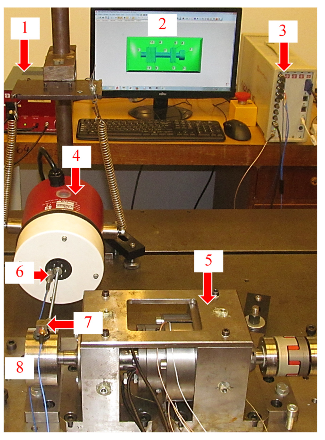
As part of the work, a measuring stand was set up, the main element of which was the model grinding spindles (Figure 1). The view of the complete test stand is shown in Figure 2. It consists of the tested spindle (5) with an active support, which was disconnected from the external drive during the tests. A replacement mass (8) is attached to its front end, to which the GW-V20 vibration exciter by Data Physics (4) is connected. The power amplifier type PA 100E by Data Physics (1) was used to power the exciter. Two piezoelectric sensors were used for the measurements.
The first, uniaxial type 62551 by Brűel & Kjaer (6), was used to measure the exciting force signal, and the second, triaxial type T356A15 by PCB Piezotronics (7), measured the vibrations of the structure. Both sensors required a DC power supply and were used to convert a high impedance charge signal into a low impedance voltage signal. They were equipped with a function called TEDS (Transducer Electronic Data Sheet) by the manufacturer, which allowed technical information about the sensor to be saved directly in its memory. Such a sensor, after connecting to the measuring system, automatically provided its calibration parameters. These sensors were connected to the Abacus measurement system using the Data Physics D780 card (3). Additionally, the system was equipped with an external monitor (2) enabling the visualization of the entire tested object.
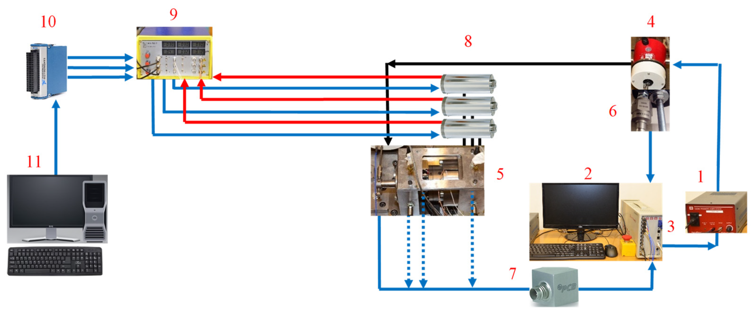
Figure 3 additionally shows a diagram of the measurement path for modal analysis. The PC (11) was used to generate a signal for a specific value of the preload force of the bearings. This signal, using the measurement card type 9264 from National Instruments (10), was converted into an electrical value and fed to the input of the piezo actuator amplifier type SVR 150/3 by Piezomechanik GmbH (9). All piezo actuators (8) of the PSt 150/40/10 type by Piezomechanik GmbH were connected to the amplifier. They had a built-in strain gauge system, which made it possible to read the values of their displacement. After setting the required preload value, the spindle system (5) was made to vibrate by means of vibration exciter type GW V20 by Data Physics (4) powered by an amplifier type PA 100E by Data Physics (1). The Abacus measurement system with D780 card by Data Physics (2) was responsible for recording the signals; the forcing (6), with the use of a one-axis piezoelectric acceleration sensor, type 62551 by Brűel & Kjaer; and the system response, using a three-axis piezoelectric acceleration sensor, type T356A15 from PCB Piezotronics (7) and for determining the parameters for the modal analysis performed.
4. Development of a Measurement Model and Research Results
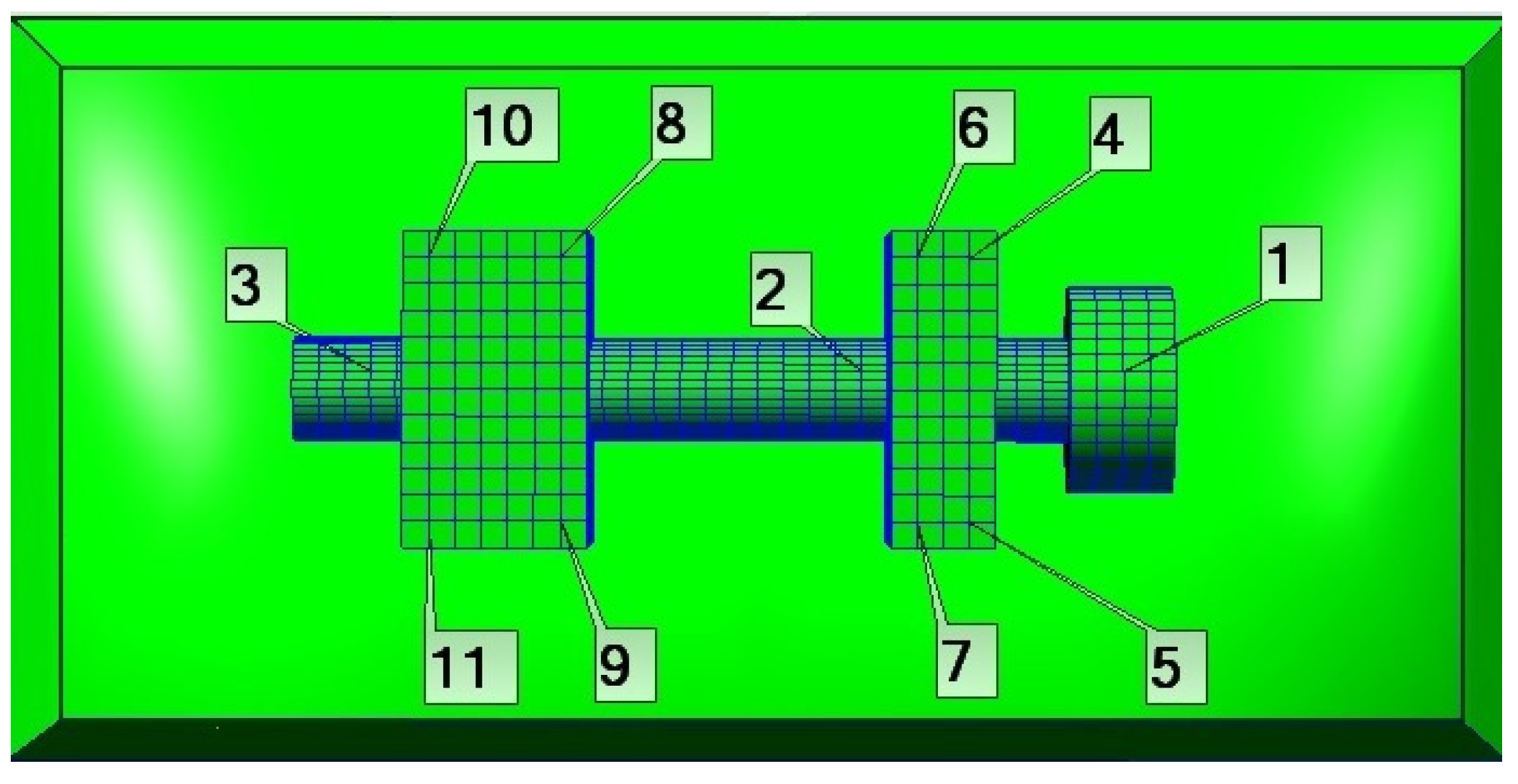
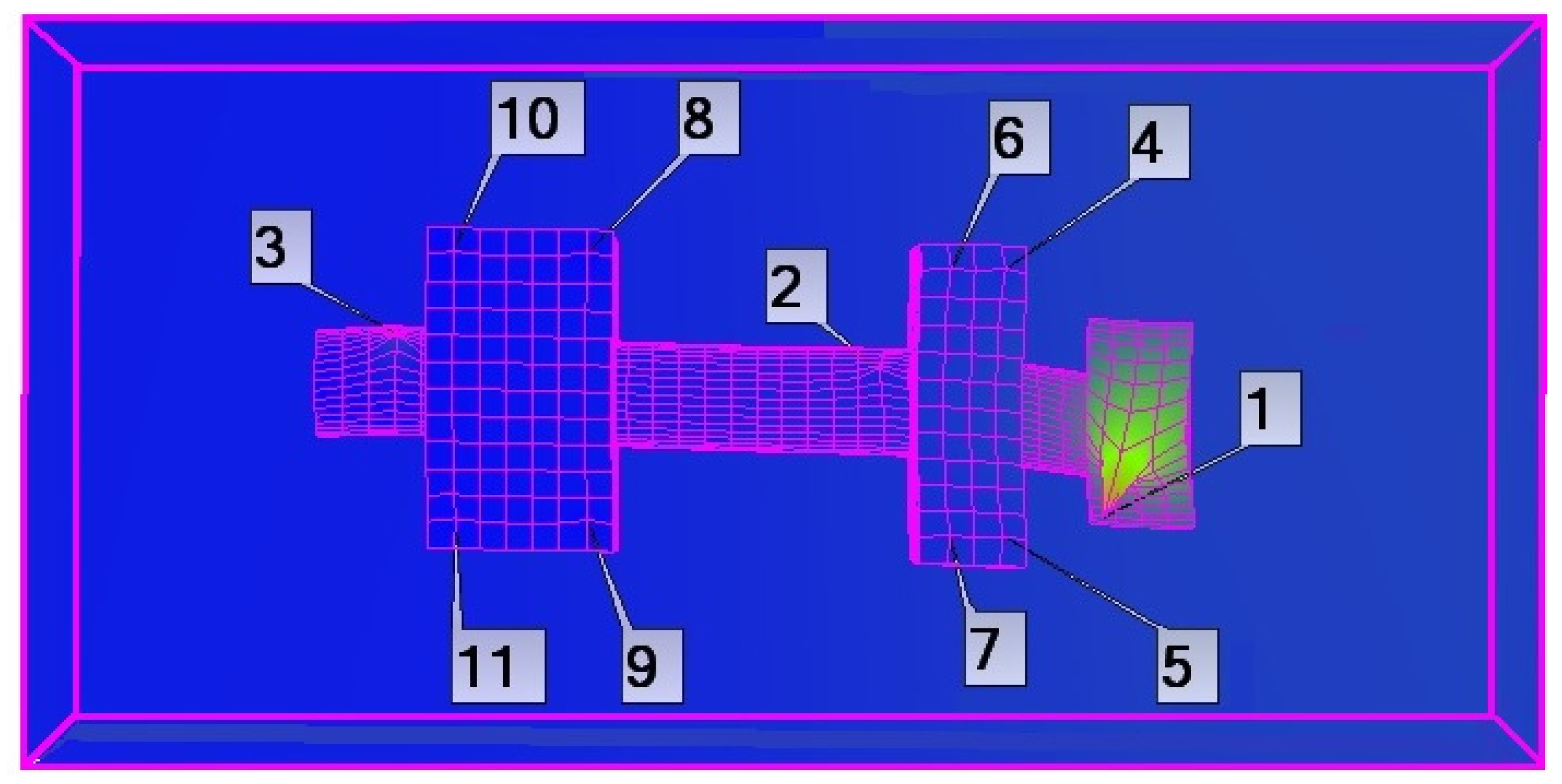
A comprehensive modal spindle analysis was carried out in two stages. For its proper performance, it was necessary to build a simplified geometric model of the spindle. It came down to modeling only two bearing supports and the spindle shaft with the equivalent mass. They were given dimensions corresponding to the actual structure. A mesh was applied to the spindle elements. Eleven measurement points were set at its nodes (Figure 4). Three of them were on the spindle shaft (start, center, end) and the remaining eight on the top surface of the bearing supports, four on each support. At these points, a measuring sensor was placed successively, which registered the behavior of the spindle system under the influence of harmonic excitations. These results were recorded using the SignalStar Vector program.
To perform the test, it was necessary to determine the parameters of the sweep, namely:
- definition of minimum and maximum frequency (Min/Max Freq);
- definition of the speed of the sweep (Rate);
- definition of the duration of the sweep (Time);
- definition of the force sensitivity (Magnitude Sensitivity);
- definition of the minimum gain level (Minimum Level (dB)).
From a practical point of view, during the measurements, it was important to select the parameters of the sweeping signal in such a way that it did not exceed the predetermined measurement limits. These exceedances usually occur where the system resonance frequencies appear. They are mainly caused by an excessive sweep speed or too high of a boost gain level. During the measurements, the SignalStar Vector software provided a visualization of the adopted “tunnel”, i.e., the range in which the control signal is to be located. The size of the “tunnel” was determined by the logarithm of the acceleration (Log.Mag.g) (we assume how large the allowed amplitude value is on the tested object), and the level of the control signal was based on the logarithm of the voltage value (Log.Mag.V) (we assume the appropriate excitation level). In the case of this work, all values of the sweep parameters were selected experimentally based on the previously performed measurements of the FFT analysis. On this basis, it was possible to conclude in what frequency range the resonance frequencies of the spindle system should be expected and at what level the speed and time of the sweep should be determined. The frequency range for the sweep was 50–1100 (Hz), and the sweep time was 15 (min). These measurements were performed for five preload states corresponding to the full range of supply voltage for piezoactuators from −30–150 (V) (the value of the preload force 60 (N), 107 (N), 200 (N), 320 (N), 430 (N)). At a given value of initial stress, the data from all eleven measurement points were successively recorded. The same measurement parameters were maintained at each point. At the same time, at each measuring point, the response of the system to the excitation was recorded three times to increase the accuracy of the results.
The obtained results were imported into the MS Scope program, which allowed for modal analysis. In this case, it was very important to correctly define the degrees of freedom and to define the directions for the measurements. After reading the measurement data, it was possible to automatically average the values for the remaining nodal points of the spindle where no measurements were made. Conducting a modal analysis based on signals recorded on a real object seems to be a better solution than only simulation tests in which some kinds of simplifications are always made. The actual measurement takes into account, e.g., assembly errors, inaccuracies in the performance of components, or contact on the contact surfaces, which is difficult to determine by simulation (surface roughness, coefficient of friction, contact surface, etc.).
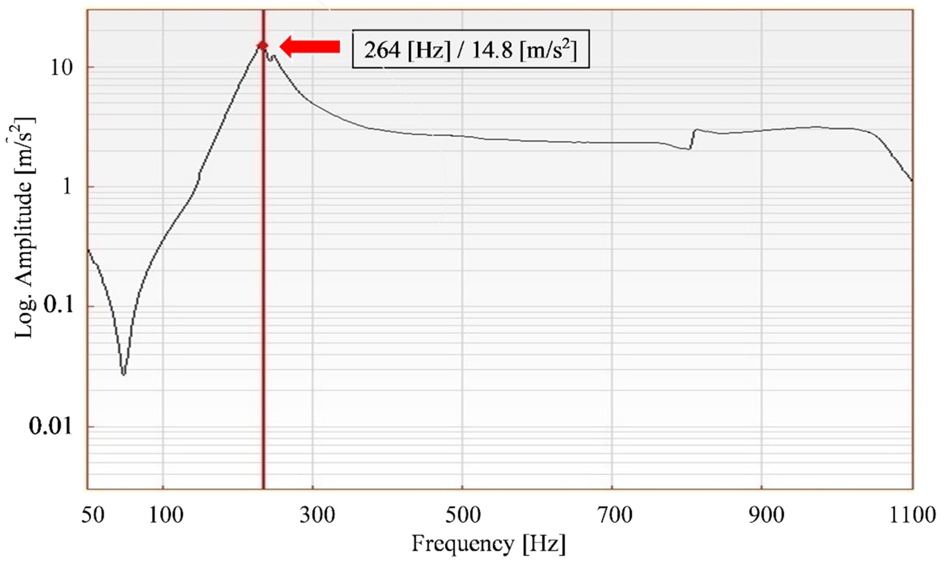
In the presented solution, the measurements were carried out in the frequency domain. This allowed the values of the resonance frequencies of the system and the corresponding acceleration amplitudes to be determined. The 3D model presented in the research was used to visualize the behavior of the spindle under the influence of the forcing forces. It was given dimensions corresponding to the actual structure. The visualization of the results was based on eleven measuring points. In this way, it is possible to present the behavior of the spindle at any frequency within the measuring range (50–1100 (Hz)) and the selected preload value. Figure 5 shows the behavior of the spindle at the frequency of 264 (Hz) and the initial voltage of the bearings corresponding to the supply voltage of piezo actuators +60 (V) of the value of 200 (N). We observe the spindle swinging on the supports. The maximum amplitude values occur in the direction of the system excitation.
Figure 6 shows an example of the amplitude frequency characteristic of the system in the full range of tested frequencies (50–1100 Hz) for the preload of 200 (N). In the given example, the resonance frequency was 264 (Hz). This frequency changed with the change of the preload of the bearings; therefore, such characteristics have been developed for different values of the preload of the bearings. Based on these characteristics, it was possible to determine the relationship between the preload of the bearings and the resonant frequency of the spindle system.
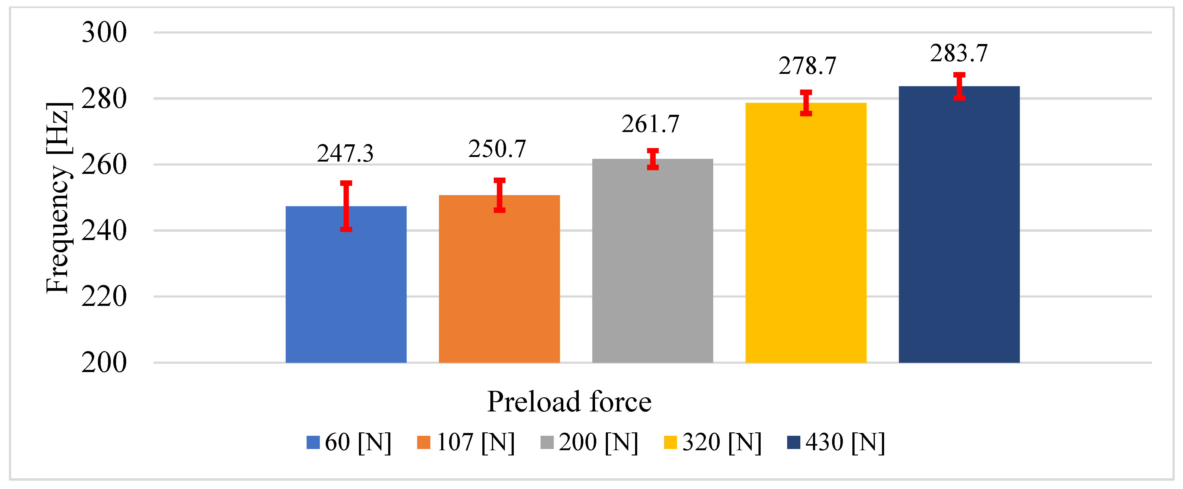
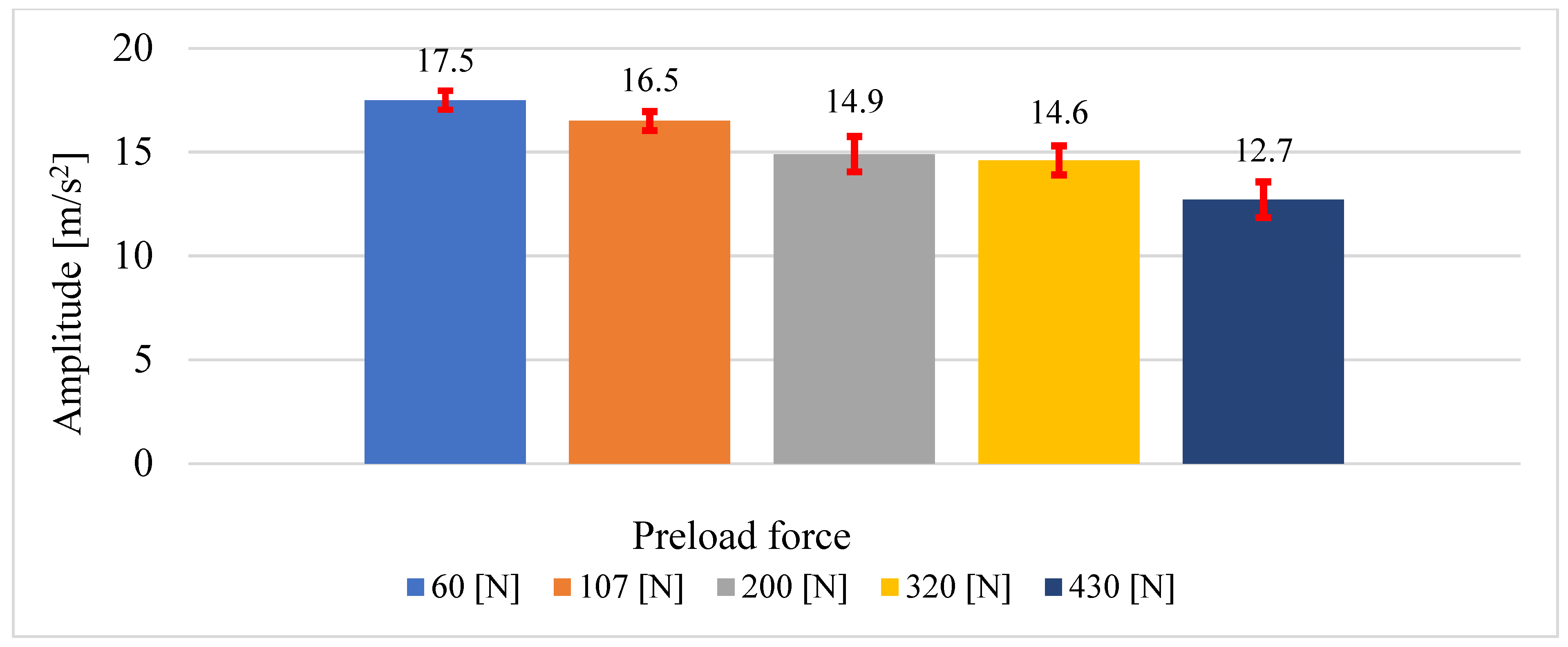
A summary of all the values of the resonance vibration frequencies and the corresponding amplitudes for the successive states of the initial tension of the spindle system is presented in Table 1. Additionally, Figure 7 and Figure 8 show bar graphs of the resonance frequencies and the corresponding amplitudes divided into five areas, each area of which corresponds to a different value of the preload of the bearings. For each area, i.e., a specific value of the preload of the bearings, the measurement was performed three times. This made it possible to calculate the value of the standard deviation and to determine the error spread as a range between the min/max value. The value of the standard deviation and the spread of errors are characterized by a small value, which clearly provides information about the high repeatability of the obtained results. It also allows for the conclusion that the obtained values of resonance frequencies are not the result of chance but clearly reflect the behavior of the real spindle system at the given parameters. If one wishes to be more certain that the tests have been performed correctly, the number of measurements should be increased; this, however, causes a significant extension of the analysis time due to the number of measurement points.
5. Summary and Conclusions
The use of commercial measuring equipment by DataPhysics for research facilitates this type of measurement. The possibility of developing a model of the tested structure makes it possible to visualize its behavior in real working conditions. The use of this system in the case of the tested spindle system allows it to be stated, on the basis of the obtained results, that the designed spindle system is dynamically sensitive to changes in the initial tension of the bearings. This sensitivity is characterized by an increase in the fundamental resonant frequency to an increase in the preload of the bearings in the system and a decrease in the corresponding amplitude. This makes it possible to use the preload state of the bearings to control changes in the frequency and form of spindle vibrations. It also makes it possible to develop an algorithm that will actively react to momentary changes in the spindle operating parameters.
Funding
This research received no external funding.
Data Availability Statement
The presented research work was carried out on the basis of the statutory funding of the Wrocław University of Technology. All results and analyzes are not made publicly available in any database.
Acknowledgments
Not applicable.
Conflicts of Interest
The author declares no conflict of interest.
References
- Jędrzejewski, J.; Kwasny, W. Modelling of angular contact ball bearings and axial displacements for high–speed spindles. CIRP Ann. Manuf. Technol. 2010, 59, 377–382. [Google Scholar] [CrossRef]
- Chen, J.S.; Chen, K.W. Bearing load analysis and control of a motorized high speed spindle. Int. J. Mach. Tools Manuf. 2005, 45, 1487–1493. [Google Scholar] [CrossRef]
- Chen, F.; Liu, G. Active damping of machine tool vibrations and cutting force measurement with a magnetic actuator. Int. J. Adv. Manuf. Technol. 2017, 89, 691–700. [Google Scholar] [CrossRef]
- Hadi Hosseinabadi, A.H.; Altintas, Y. Modeling and active damping of structural vibration in machine tools. CIRP JMST 2014, 7, 246–257. [Google Scholar] [CrossRef] [Green Version]
- Hwang, Y.K.; Lee, C.M. Development of a newly structured variable preload control device for a spindle rolling bearing by using an electromagnet Int. J. Mach. Tools Manuf. 2010, 50, 253–259. [Google Scholar] [CrossRef]
- Sikorski, J.; Pawłowski, W. Innovative mechanisms of introducing preload in angular contact bearing systems. Mechanik 2018, 2, 138–140. (In Polish) [Google Scholar] [CrossRef] [Green Version]
- Jiang, S.; Mao, H. Investigation of Variable Optimum Preload for a Machine Tool Spindle. Int. J. Mach. Tools Manuf. 2010, 50, 19–28. [Google Scholar] [CrossRef]
- Parus, A.; Chodzko, M.; Hoffman, M. Elimination of self-excited vibrations using an active machining chuck. Modelowanie Inzynierskie 2011, 42, 325–332. (In Polish) [Google Scholar]
- Basavaraj Swamy, S. Design, static, and modal analysis of high speed motorized milling spindle. Int. Res. J. Eng. Technol. 2018, 5, 787–799. [Google Scholar]
- Kong, J.; Cheng, X. Modal Analysis of CNC Lathe’s Spindle Based on Finite Element. Adv. Eng. Res. 2017, 148, 318–321. [Google Scholar]
- Guo, M.; Li, B.; Yang, J.; Liang, S. Study of experimental modal analysis method of machine tool spindle system. J. Vibroeng. 2015, 17, 3173–3186. [Google Scholar]
- Li, B.; Li, L.; He, H.; Mao, X.; Jiang, X.; Peng, Y. Research on modal analysis method of CNC machine tool based on operational impact excitation. Int. J. Adv. Manuf. Technol. 2019, 103, 1155–1174. [Google Scholar] [CrossRef]
- Özşahin, O.; Ritou, M.; Budak, E.; Rabréau, C.; Le Loch, S. Identification of spindle dynamics by receptance coupling for non-contact excitation system. Procedia CIRP 2019, 82, 273–278. [Google Scholar] [CrossRef]
- Bąk, P.; Jemielniak, K. Automatic experimental modal analysis of milling machine tool spindles. J. Eng. Manuf. 2016, 230, 1673–1683. [Google Scholar] [CrossRef]
- Pawłowski, W.; Bojanowski, S. Theoretical modal analysis of the headstock assembly of the hole grinder. Mechanik 2011, 11, 870–874. (In Polish) [Google Scholar]
- Ewins, D.J. Modal: Theory, Practice and Application, 2nd ed.; Research Studies Press Ltd.: Baldock, UK, 2000. [Google Scholar]
- Budak, E. Dynamic Analysis and Control; Springer: London, UK, 2009. [Google Scholar]
- Maia, N.M.M.; Silva, J.M.M. Modal analysis identification techniques. Phil. Trans. R. Soc. A 2001, 359, 29–40. [Google Scholar] [CrossRef]
- Altintas, Y. Machining Process Modeling, Machine Tap Testing and Chatter Vibration Avoidance; University of British Columbia: Vancouver, BC, Canada, 2002. [Google Scholar]
- Pop, D.; Morar, L.; Câmpean, E.; Tănase, I. Experimental modal analysis of a milling machine spindle—tool holder—cutter assembly. Acta Technol. Napoc. Ser. Appl. Math. Mech. 2012, 55, 233–238. [Google Scholar]
- Lajmert, P.; Sikora, M.; Kruszyński, B.; Wrąbel, D. Application of experimental and numerical modal analysis to determine the dynamic properties of a center cylindrical grinder. Mechanik 2013, 8/9, 283–290. (In Polish) [Google Scholar]
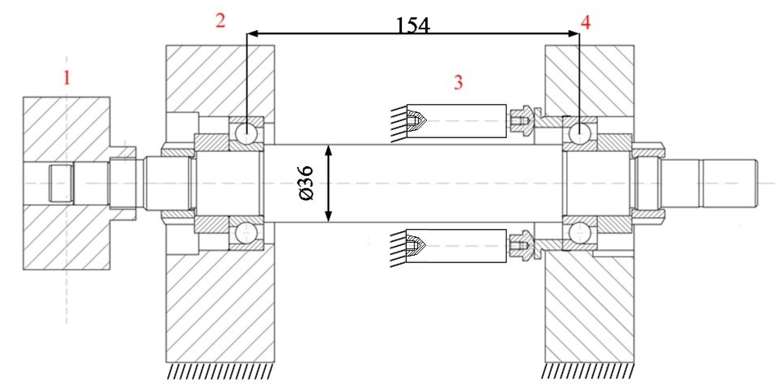
Figure 1.
Arrangement diagram of accelerometers on the spindle shaft, 1—substitute weight, 2—front support, 3—piezo actuators, 4—rear support.
Figure 1.
Arrangement diagram of accelerometers on the spindle shaft, 1—substitute weight, 2—front support, 3—piezo actuators, 4—rear support.

Figure 2.
View of the test stand used in modal analysis.

Figure 3.
Diagram of the measuring track for the test stand for modal analysis of the spindle system with active regulation of the initial tension of the bearings.
Figure 3.
Diagram of the measuring track for the test stand for modal analysis of the spindle system with active regulation of the initial tension of the bearings.

Figure 4.
Geometric structure of the spindle assembly model for modal analysis with the distribution of measurement points.
Figure 4.
Geometric structure of the spindle assembly model for modal analysis with the distribution of measurement points.

Figure 5.
Visualization of the behavior of the spindle system for the frequency of 264 (Hz) at the supply voltage of 60 (V) (200 (N)) piezoactuators.
Figure 5.
Visualization of the behavior of the spindle system for the frequency of 264 (Hz) at the supply voltage of 60 (V) (200 (N)) piezoactuators.

Figure 6.
An exemplary amplitude-frequency characteristic of a spindle for the bearing preload equal to 60V (200 (N)) measured at the spindle tip in the direction of the input.
Figure 6.
An exemplary amplitude-frequency characteristic of a spindle for the bearing preload equal to 60V (200 (N)) measured at the spindle tip in the direction of the input.

Figure 7.
Comparison of the average values of the resonant frequency of the spindle system measured at the spindle tip in the direction of the input operation at different bearing preload conditions.
Figure 7.
Comparison of the average values of the resonant frequency of the spindle system measured at the spindle tip in the direction of the input operation at different bearing preload conditions.

Figure 8.
Comparison of the average values of the acceleration amplitudes for the resonance frequency of the spindle system measured in the direction of the input action at different bearing preload conditions.
Figure 8.
Comparison of the average values of the acceleration amplitudes for the resonance frequency of the spindle system measured in the direction of the input action at different bearing preload conditions.


Table 1.
Comparison of resonant vibration frequencies and amplitudes for variable bearing preload conditions.
Table 1.
Comparison of resonant vibration frequencies and amplitudes for variable bearing preload conditions.
| −30 V/60 (N) | 15 V/107 (N) | 60V/200(N) | 105V/320(N) | 150V/430(N) | ||||||
|---|---|---|---|---|---|---|---|---|---|---|
| Frequency (Hz) | Amp. (m/s2) | Frequency (Hz) | Amp. (m/s2) | Frequency (Hz) | Amp. (m/s2) | Frequency (Hz) | Amp. (m/s2) | Frequency (Hz) | Amp. (m/s2) | |
| 247.3 | 17.5 | 250.7 | 16.5 | 261.7 | 14.9 | 278.7 | 14.6 | 283.7 | 12.7 | |
| s—standard deviation | 7.02 | 0.46 | 4.51 | 0.46 | 2.52 | 0.85 | 3.21 | 0.70 | 3.51 | 0.86 |
Publisher’s Note: MDPI stays neutral with regard to jurisdictional claims in published maps and institutional affiliations. |
© 2021 by the author. Licensee MDPI, Basel, Switzerland. This article is an open access article distributed under the terms and conditions of the Creative Commons Attribution (CC BY) license (https://creativecommons.org/licenses/by/4.0/).
Share and Cite
MDPI and ACS Style
Turek, P. Determination of the Natural Frequency of the Model Spindle System with Active Regulation of the Initial Tension of the Bearings. Lubricants 2021, 9, 68. https://0-doi-org.brum.beds.ac.uk/10.3390/lubricants9070068
AMA Style
Turek P. Determination of the Natural Frequency of the Model Spindle System with Active Regulation of the Initial Tension of the Bearings. Lubricants. 2021; 9(7):68. https://0-doi-org.brum.beds.ac.uk/10.3390/lubricants9070068
Chicago/Turabian StyleTurek, Paweł. 2021. "Determination of the Natural Frequency of the Model Spindle System with Active Regulation of the Initial Tension of the Bearings" Lubricants 9, no. 7: 68. https://0-doi-org.brum.beds.ac.uk/10.3390/lubricants9070068
Note that from the first issue of 2016, this journal uses article numbers instead of page numbers. See further details here.