Effects of Side Flushing and Multi-Aperture Inner Flushing on Characteristics of Electrical Discharge Machining Macro Deep Holes

Department of Industrial Engineering, Faculty of Engineering, King Mongkut’s Institute of Technology Ladkrabang, Bangkok 10520, Thailand
*
Author to whom correspondence should be addressed.
Metals 2021, 11(1), 148; https://0-doi-org.brum.beds.ac.uk/10.3390/met11010148
Submission received: 4 November 2020
/
Revised: 23 December 2020
/
Accepted: 28 December 2020
/
Published: 13 January 2021
Abstract
:This research investigates the effect of machining parameters on material removal rate, electrode wear ratio, and gap clearance of macro deep holes with a depth-to-diameter ratio over four. The experiments were carried out using electrical discharge machining with side flushing and multi-aperture flushing to improve the machining performance and surface integrity. The machining parameters were pulse on-time, pulse off-time, current, and electrode rotation. Response surface methodology and the desirability function were used to optimize the electrical discharge machining parameters. The results showed that pulse on-time, current, and electrode rotation were positively correlated with the material removal rate. The electrode wear ratio was inversely correlated with pulse on-time and electrode rotation but positively correlated with current. Gap clearance was positively correlated with pulse on-time but inversely correlated with pulse off-time, current, and electrode rotation. The optimal machining condition of electrical discharge machining with side flushing was 100 µs pulse on-time, 20 µs pulse off-time, 15 A current, and 70 rpm electrode rotation; and that of electrical discharge machining with multi-aperture flushing was 130 µs, 2 µs, 15 A, and 70 rpm. The novelty of this research lies in the use of multi-aperture flushing to improve the machining performance, enable a more uniform GC profile, and minimize the incidence of recast layer.
1. Introduction
Electrical discharge machining (EDM) is a non-traditional machining method that relies on the electro-thermal effect of the discharge current between the electrode and workpiece to remove material in dielectric fluid. EDM is used to fabricate machining holes in tool materials [1,2,3]. There are three groups of EDM holes, depending on the cross-sectional area of the electrode: micro (cross-sectional area of electrode <1 mm2), meso (<10 mm2), and macro (>10 mm2).
The characteristics of the EDM deep hole are subject to several machining parameters, such as the flushing method and machining depth [4,5]. Non-ideal EDM conditions result in gap clearance (GC) distortion. Figure 1a–c show three types of gap clearance distortion: (a) reverse taper, (b) V-shaped taper, and (c) barrel taper [6,7,8,9]. The gap clearance distortion worsens as the ratio of hole depth to electrode diameter (depth-to-diameter ratio) increases.
The non-flushing EDM technology is unsuitable for deep holes with large depth-to-diameter ratios due to poor debris removal [10]. In [11], Tanjilul et al. investigated the effect of debris particle size and flushing mechanism on debris removal efficiency. The disproportionate depth-to-diameter ratio (i.e., the depth of the copper electrode is excessively greater than its diameter) induced distortion in the cavity wall. Specifically, in this research, the copper electrode depth and diameter are 50 mm and 12 mm, resulting in a disproportionate depth-to-diameter ratio. Meanwhile, pulse on-time and electrical current influenced the deep hole profile [12].
Flushing plays a crucial role in the EDM process, since flushing removes debris from the machining gap and affects the EDM performance and deep hole characteristics [13]. Side flushing is conventionally used in EDM due to its simplicity and relatively efficient debris removal. The accumulated debris in the machining gap increases the electrical conductivity of dielectric fluid, giving rise to secondary spark and poor EDM performance.
In deep-hole EDM with side flushing, the increased viscosity of the dielectric fluid in the narrow machining gap hinders the removal of debris and air bubbles. The inefficient removal of debris and bubbles induces a secondary spark, resulting in low EDM performance. As a result, alternative flushing methods have been proposed, including linear motor equipped [14], mono hole inner flushing [15], side suction flushing [16], and modified electrodes [17]. In [14,15,16,17], single-channel, multi-channel, and channel-less cylindrical electrodes were comparatively investigated. The results showed that compared to the multi-channel electrode, the single-channel electrode is less ideal for blind-hole drilling due to spike at the center of the hole base. The channel-less cylindrical electrode is commonly used in die sinking.
Specially designed electrodes were also proposed for specific machining tasks. In [18], an inclined multi-hole electrode was proposed to reduce the accumulation of debris in the machining gap. In [19], a novel flushing technique using multiple hollow electrodes bundled together was investigated in comparison with side flushing using a single solid electrode in machining titanium alloy.
The material removal rate and electrode wear ratio are commonly used to assess the EDM performance. Gap clearance determines the dimensional accuracy and quality of machined holes. The EDM performance metrics (material removal rate, electrode wear ratio, and gap clearance) deteriorate as the hole depth increases. Nevertheless, the deterioration could be mitigated by optimizing the machining parameters, such as the pulse on-time, pulse off-time, current, electrode rotation, flushing method, machining depth, and electrode different designs. Open-gap voltage also affects the size of the spark gap. Specifically, in high-conductivity workpieces and electrodes.
The trade-off nature of the material removal rate, electrode wear ratio, and gap clearance presents challenges to EDM machine operators [20,21,22]. In [23], a mathematical model, based on response surface methodology and desirability function, was proposed to analyze the effect of EDM parameters on metal matrix composite (MMC) material. In [24], a response surface methodology based on a mathematical model was proposed to establish the relationship between EDM parameters (pulse on-time, gap voltage, and current) and material removal rate, gap size, roughness average, and electrode wear ratio. In [25], a response surface methodology based on the desirability function was utilized to investigate the EDM of tool steels, and it was found that a longer pulse on-time increased the material removal rate while reducing the electrode wear ratio.
The effects of machining parameters on the EDM performance and characteristics of EDM micro deep holes have been extensively researched [26,27,28]. However, research on the effect of machining parameters on the EDM macro deep holes is very limited. In practice, in macro deep hole machining, EDM with side flushing is prone to gap clearance distortion, and the distortion worsens as the depth-to-diameter ratio increases [29].
As a result, this research proposes EDM with multi-aperture inner flushing for machining macro deep holes with a depth-to-diameter ratio greater than four. In addition, the effects of machining parameters on the material removal rate, electrode wear ratio, and gap clearance of EDM with conventional side flushing and proposed multi-aperture flushing were investigated and compared. The machining parameters included pulse on-time, pulse off-time, current, and electrode rotation. Given the trade-off nature of the material removal rate, electrode wear ratio, and gap clearance, response surface methodology and desirability function were used to optimize the machining conditions of EDM with side flushing and multi-aperture flushing. This study also examined the effect of side flushing and multi-aperture flushing on the gap clearance profile and surface characteristics. This research lies in the use of multi-aperture flushing to improve the flushing ability and removal of debris from the machining gap during the EDM of the deep hole process, leading to the EDM deep holes performance and integrity of the machined surface.
2. Materials and Methods
2.1. Experimental Materials and Setup
In this research, an ARISTECH CNC-EDM 430 electrical discharge machine (Aristech, Taiwan) with a positive-polarity copper electrode was used to machine AISI P20 plastic mold steel. The mold steel was 57 mm × 55 mm × 12 mm (W × L × T) in dimension, and the electrode was of copper (99.90% purity) and 12 mm × 100 mm (Ø × L) in dimension.
Prior to machining, the mold steel (i.e., workpiece) was polished by a surface grinder and rotated by 90°. The rotated workpiece was 57 mm × 12 mm × 55 mm (W × L × T) in dimension, and the machining hole was 50 mm deep. The macro deep holes were fabricated by EDM with conventional side flushing and proposed multi-aperture flushing. The dielectric fluid was EDM oil of commercial grade (TOTAL DIEL MS 700, Total Lubrifiants, Nanterre Cedex, France). The flushing pressure of the side flushing and proposed multi-aperture flushing were carried out under the same conditions (0.098 MPa). Table 1 tabulates the chemical composition of the experimental plastic mold steel.
Figure 2a shows the schematics of EDM macro deep hole experimental setup. A specially designed rotary chuck was used in the EDM deep hole process and outfitted to the EDM machine. The rotary chuck was employed to rotate the electrode, resulting in improved flushing and debris removal from the machining gap. Figure 2b shows a prototype of the multi-aperture inner flushing copper electrode. The inner and outer diameters of the copper electrode are 8.4 mm and 12 mm, respectively. The electrode has 12 inner apertures at the base (1 mm in diameter). The flushing pressure was 0.098 MPa.
Given the depth-to-diameter ratio greater than four (machining depth of 50 mm and copper electrode diameter of 12 mm), the gap clearance (GC) between the electrode and workpiece is susceptible to distortion. In this research, the GC profiles of deep holes machined with side flushing and multi-aperture inner flushing were characterized by using a 3D handy scanner (Creaform REVscan, Creaform Inc., Levis, QC, Canada) and noncontact laser scanning confocal microscope (LEXT OLS 5000, Olympus, Tokyo, Japan). The copper electrode diameter was determined by the 3D handy scanner, and the EDM deep hole diameter was determined by the noncontact laser scanning confocal microscope. To determine distortion, the GC was measured at six locations (1, 10, 20, 30, 40, and 50 mm) in the machining direction, as shown in Figure 3. The maximum distortion of the six locations was used as the GC of a given EDM specimen because the maximum distortion reflects the effect of the disproportionate depth-to-diameter ratio (i.e., >4). The microstructure of the copper electrode and machined workpiece was analyzed by scanning electron microscopy (SEM) (JSM-5800LV, JEOL, Peabody, MA, USA), and the elemental composition was analyzed by energy-dispersive spectrometry (EDS) (X-Max, OXFORD Instruments, Concord, MA, USA). The effect of a secondary spark on the copper electrode of EDM with side flushing and multi-aperture flushing were characterized by using digital microscope (DSX 1000, Olympus, Japan).
2.2. Experimental Design
RSM-based central composite design (CCD) was used to individually optimize the machining parameters of EDM deep hole that maximized material removal rate (MRR) while minimizing electrode wear ratio (EWR) and gap clearance (GC). There were four machining parameters: pulse on-time, pulse off-time, current, and electrode rotation. Table 2 tabulates the design scheme of the machining parameters and their levels: low, center, and high. The CCD generated 31 machining conditions, consisting of 16 factorial points, 7 center points, and 8 axial points. The EDM parameters and corresponding parametric values were based on previous studies on EDM using modified copper electrodes [4,30,31].
In this research, the workpiece and electrode were weighed before and after the deep hole machining with 0.001-g precision scale. The MRR and EWR was calculated by Equation (1) and (2), respectively.
In Equation (1), Ww1 and Ww2 represent the weight of the workpiece before and after deep hole machining; and ρw and Mt stand for the density of the workpiece (AISI P20, 7.786 g/cm3) and EDM machining time (min), respectively. In Equation (2), WE1 and WE2 represent the electrode weight before and after machining; and ρE is the density of copper electrodes (8.94 g/cm3) [20,24].
2.3. Multi-Response Optimization
Due to the trade-off nature of the responses (MRR, EWR, and GC), this research utilized the desirability function to collectively optimize the machining parameters. A desirability function assesses the effectiveness of a collection of machining parameters in satisfying the response goals. Specifically, the composite desirability function (D) is the summation of individual desirabilities (di).
The individual desirability scores (di) range from 0 to 1, where 0 indicates a response outside the parameter boundaries and 1 indicates an ideal response. Higher individual desirabilities (di) contribute to a higher composite desirability (D) [32]. The individual desirability functions for maximum and minimum responses are expressed in Equations (3) and (4), respectively. In this research, the response goals are the maximum MRR and minimum EWR and GC.
where di is the individual desirability function, Li is the lower limit, Ui is the upper limit, yi is the response, Ti is the target response, and w is the individual desirability weight. The desirability weight was varied between 0.1 and 10, depending on the emphasis given to a particular response.
Likewise, the composite desirability function (D) scores range from 0 to 1, where 0 indicates a response outside the parameter boundaries and 1 indicates an ideal response. The desirability weight (w) was varied between 0.1 and 10, depending on the emphasis given to a particular response [33]. The composite desirability function (D) to optimize a collection of machining parameters is expressed in Equation (5).
3. Results and Discussion
3.1. Effect of the Machining Parameters on MRR of EDM With Side and Multi-Aperture Flushing
Table 3 tabulates the analysis of variance (ANOVA) results of the reduced regression model for MRR of EDM with side flushing (MRRsf). MRRsf was significantly correlated to pulse on-time (A), current (C), current squared (C2), and interaction between A and C (p < 0.05), with R2 and adjusted R2 of 85.33% and 83.07%. The reduced multiple regression model for MRRsf is expressed in Equation (6).
MRRsf = 22.0391 − 0.0619A − 3.2590C + 0.1558C2 + 0.0081AC
Figure 4 illustrates the MRR of EDM with side flushing as a function of pulse on-time and current. MRRsf is positively correlated with pulse on-time and current. A longer pulse on-time and higher current generated high machining temperatures and high-intensity electrical discharge, resulting in efficient material removal. In Figure 4, the maximum MRRsf was achieved under 150 µs pulse on-time and 15 A current.
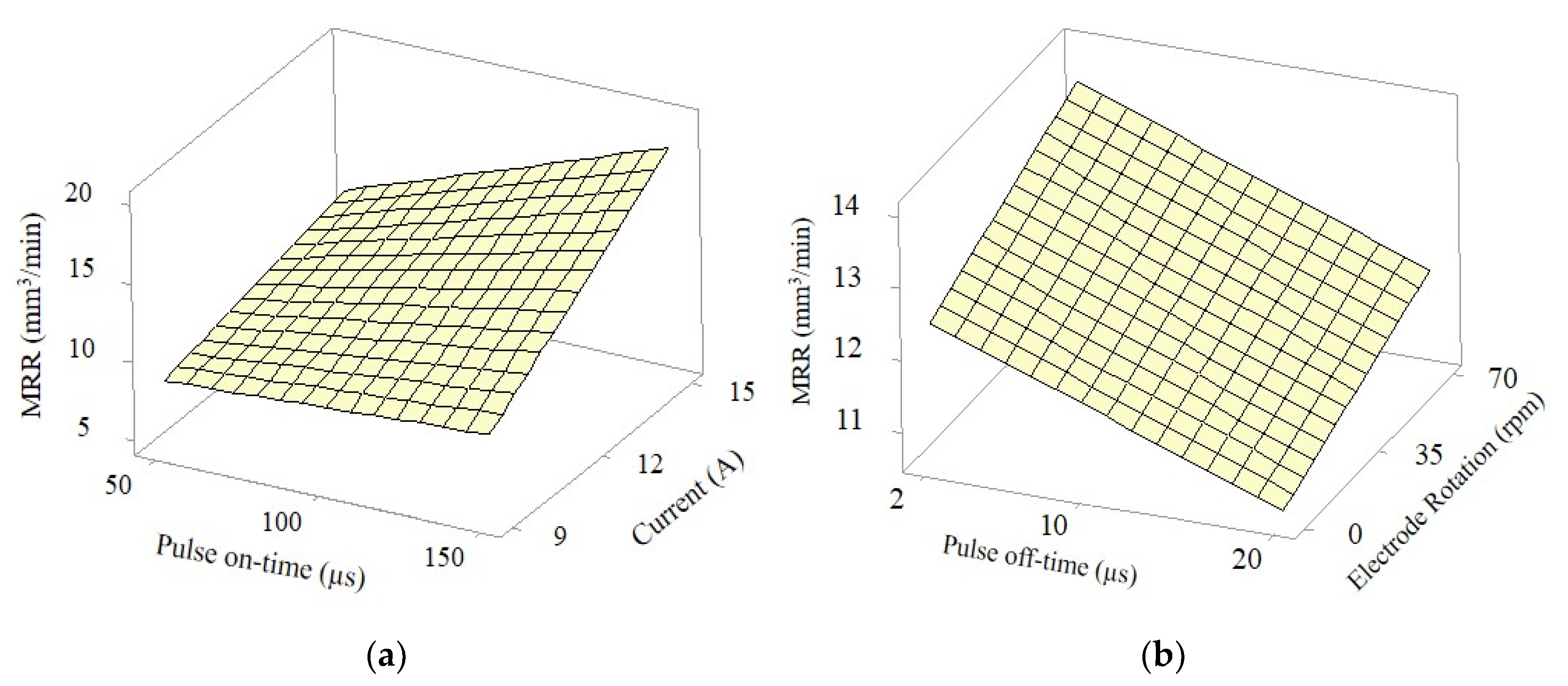
Table 4 presents the ANOVA results of the reduced regression model for MRR of EDM with multi-aperture flushing (MRRmf). MRRmf was significantly correlated to pulse on-time (A), pulse off-time (B), current (C), electrode rotation (D), and AC interaction (p < 0.05), with R2 and adjusted R2 of 92.64% and 91.16%. Equation (7) is the reduced multiple regression model for MRRmf.
MRRmf = 8.90 − 0.0805A − 0.1016B − 0.038C + 0.01709D + 0.01021AC
In Figure 5a, MRRmf was positively correlated with pulse on-time and current. A longer pulse on-time and higher electrical current generated higher temperatures in the machining gap, resulting in higher material removal efficiency. A shorter pulse off-time and faster electrode rotation improved the material removal in the machining gap (Figure 5b). Based on Figure 5a,b, the maximum MRRmf was achieved under 150 µs pulse on-time, 2 µs pulse off-time, 15 A current, and 70 rpm electrode rotation.
3.2. Effect of the Machining Parameters on EWR of EDM with Side and Multi-Aperture Flushing
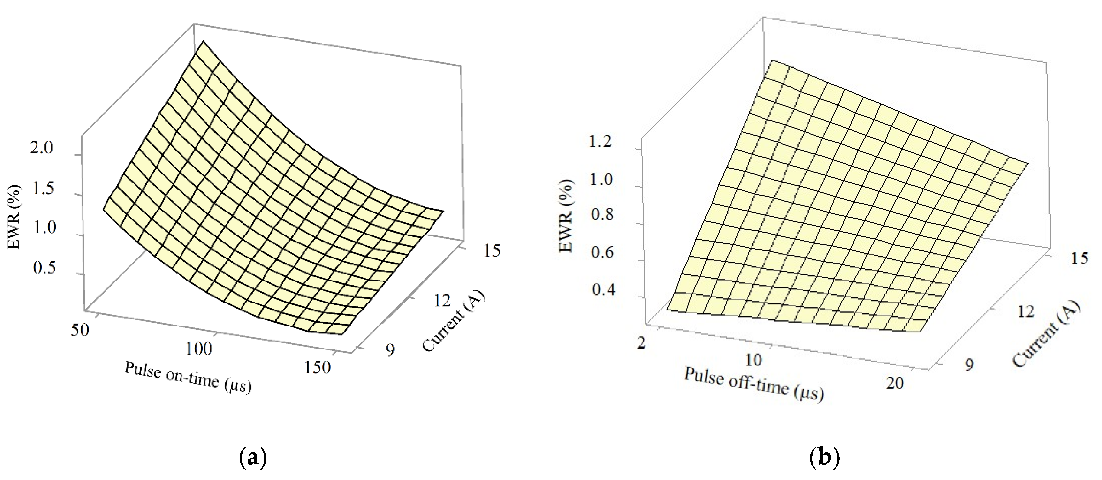
Table 5 presents the ANOVA results of the reduced regression model for EWR of EDM with side flushing (EWRsf). EWRsf was significantly correlated to pulse on-time (A), current (C), electrode rotation (D), square of the pulse on-time (A2), and AC and BC interactions (p < 0.05), with R2 and adjusted R2 of 93.24% and 91.18%. The reduced multiple regression model for EWRsf is expressed in Equation (8).
EWRsf = 0.887 − 0.0320A + 0.0423B + 0.2355C − 0.0034D + 0.00015A2 − 0.000975AC − 0.00412BC
Figure 6a,b illustrates the EWR of EDM with side flushing (EWRsf) as a function of pulse on-time and current, and pulse off-time and current. In Figure 6a, the pulse on-time was inversely correlated with EWR. Under 50 µs pulse on-time condition, the high EWRsf was attributable to the movement of electrons from the workpiece (cathode) to the positive-polarity electrode. On the other hand, a longer pulse on-time (150 µs) expanded the plasma channel radius, leading to the movement of positive ions from the positive-polarity electrode to the workpiece and the collision of positive ions. As a result, the EWR decreased with increase in pulse on-time [34].
In Figure 6b, at 2 µs pulse off-time, EWRsf significantly increased with higher current. On the other hand, at longer pulse off-time (20 µs), EWRsf was lower as the current increased. Based on Figure 6a,b, the minimum EWRsf was achieved with 150 µs pulse on-time, 20 µs pulse off-time, and 9 A current.
More specifically, in Figure 6a, given 50 µs pulse on-time, EWR significantly increased with the increase in the current. Meanwhile, under the longer pulse on-time (150 µs), a higher current had a minimal effect on EWR. The longer pulse on-time and higher electrical current induced the formation of film-like carbon black on the copper electrode as carbon in the workpiece migrated to the electrode [35]. The film-like carbon black protected against the electrode wear, resulting in lower EWR [2].
Figure 7a shows the film-like carbon black on the electrode and the SEM micrograph at 40 mm depth, given 150 µs pulse on-time and 15 A current. Figure 7b illustrates the corresponding EDS compositional analysis, with 51.89% carbon element, 9.85% oxide element, 25.51% copper element, 11.85% Fe element, and other elements.
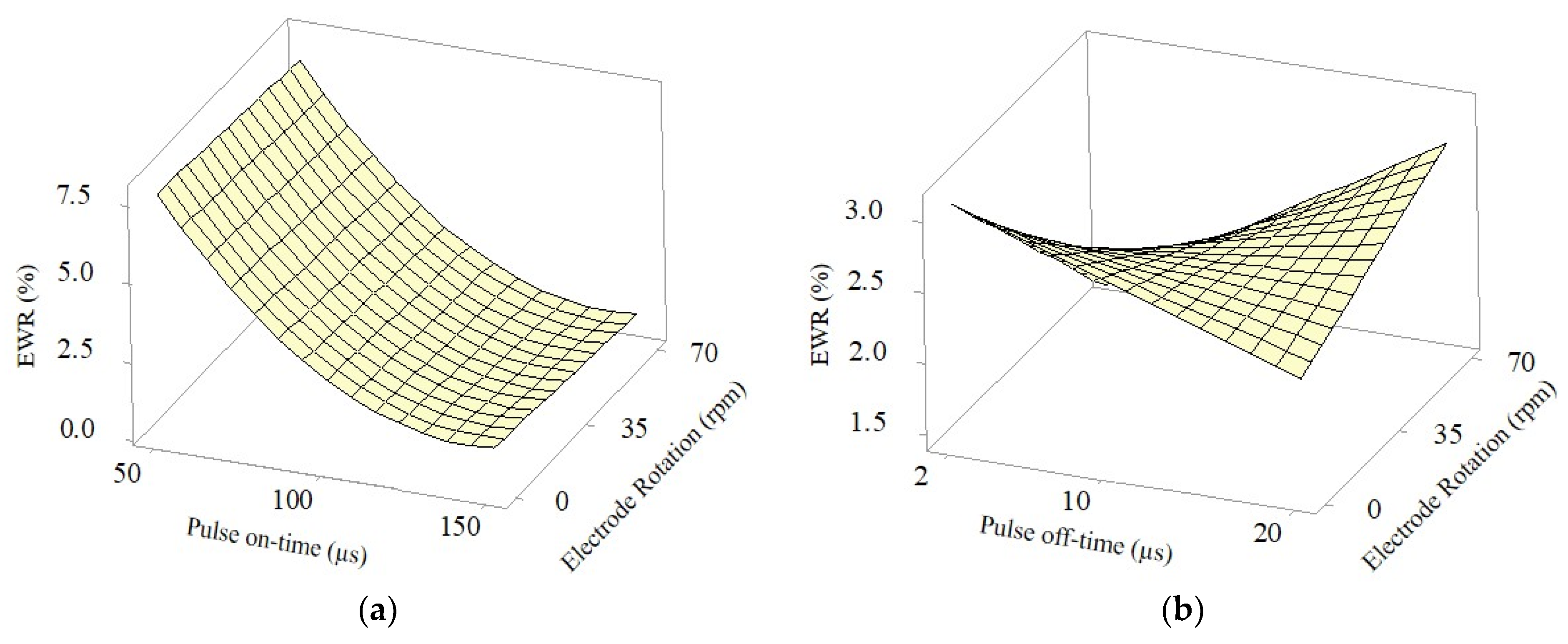
The ANOVA results of the reduced regression model for EWR of EDM with multi-aperture flushing (EWRmf) are tabulated in Table 6. EWRmf was significantly correlated to pulse on-time (A), square of pulse on-time (A2), and pulse off-time (B), current (C) and pulse off-time (B), electrode rotation (D) interaction (p < 0.05), with R2 and adjusted R2 of 91.31% and 87.59%. The reduced multiple regression model for EWRmf is expressed in Equation (9).
EWRmf = 14.80 − 0.2181A + 0.190B + 0.219C − 0.0843D + 0.000756A2 + 0.000093AD − 0.01976BC + 0.001769BD + 0.00404CD
In Figure 8a, EWRmf and pulse on-time were inversely correlated, and the electrode rotation had a negligible effect on EWRmf. In Figure 8b, at 2 µs pulse off-time, EWRmf was inversely correlated to the electrode rotation. The lower EWRmf was attributable to greater flushing capability of the multi-aperture inner scheme, which resulted in higher debris removal efficiency as the electrode rotation increased. At 20 µs pulse off-time, EWRmf increased with increase in the electrode rotation. Based on Figure 8a,b, the minimum EWRmf was achieved with 150 µs pulse on-time, 2 µs pulse off-time, and 70 rpm electrode rotation.
3.3. Effect of the Machining Parameters on GC of EDM with Side and Multi-Aperture Flushing
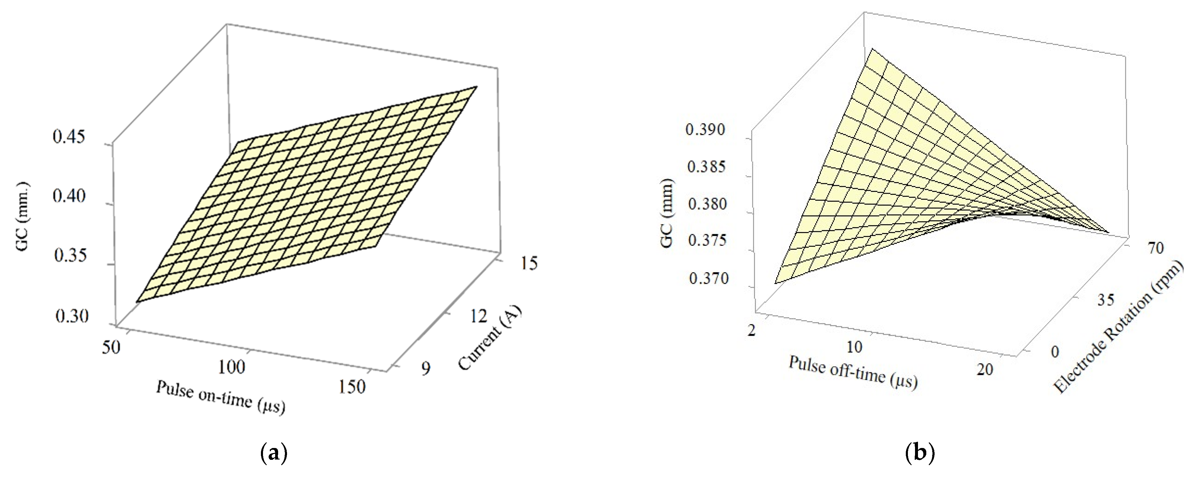
Table 7 presents the ANOVA results of the reduced regression model for the GC of EDM with side flushing (GCsf). GCsf was significantly correlated to pulse on-time (A), current (C), and BD and CD interactions (p < 0.05), with R2 and adjusted R2 of 90.26% and 87.82%. The reduced multiple regression model for GCsf is expressed in Equation (10).
GCsf = 0.0843 + 0.000398A + 0.000434B + 0.005006C + 0.0006D − 0.000014BD − 0.000037CD
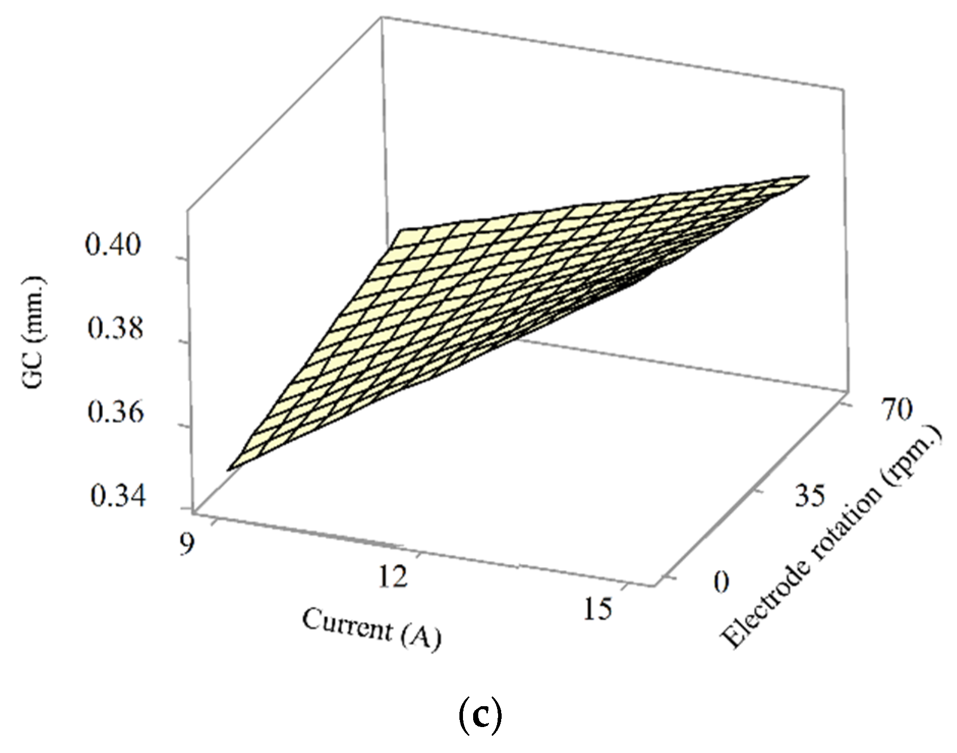
Figure 9a–c illustrates the GC of EDM with side flushing (GCsf) as a function of pulse on-time and current; pulse off-time and electrode rotation; and current and electrode rotation, respectively. In Figure 9a, GCsf was positively correlated to pulse on-time and electrical current. With side flushing, a longer pulse on-time and higher current generated higher temperatures and higher intensity discharge, enhancing machining efficiency. Nevertheless, the enhanced machining resulted in the rapid accumulation of debris and eventually wider GCsf, given the limited debris removal efficiency of side flushing [25]. GCsf became disproportionately wider as the depth-to-diameter ratio increased.
In Figure 9b, a longer pulse off-time and faster rotational speed resulted in narrower GCsf as sufficient time was provided for the removal of debris. In Figure 9c, GCsf became wider as the current increased. Nevertheless, the CG distortion was partially offset with increased electrode rotation speed. The minimum GCsf was achieved with 50 µs pulse on-time, 2 µs pulse off-time, 9 A current, and 70 rpm electrode rotation.
Table 8 presents the ANOVA results of the reduced regression model for GC of EDM with multi-aperture flushing (GCmf). GCmf was significantly correlated to pulse on-time (A), current (C), electrode rotation (D), and AB and AC interactions (p < 0.05), with R2 and adjusted R2 of 78.34% and 70.46%. The reduced multiple regression model for GCmf is in Equation (11).
GCmf = 0.1758 − 0.000449A − 0.002395B − 0.00141C − 0.00045D + 0.000001D2 + 0.000022AB + 0.000041AC + 0.000001AD
In Figure 10a, GCmf was positively correlated to pulse on-time and pulse off-time. A longer pulse on-time and longer pulse off-time increased the material removal efficiency and accumulation of debris. By comparison, GCmf was narrower than GCsf due to the greater debris removal efficiency of multi-aperture flushing. In Figure 10b, a longer pulse on-time increased the width of GCmf, and the distortion worsened with increase in the electrical current. In Figure 10c, the GCmf width increased with increase in the pulse on-time, while increased electrode rotation speeds minimally affected the GCmf.
3.4. Multi-Response Optimization Using Desirability Function.
The machining parameters (pulse on-time, pulse off-time, current, and electrode rotation) were collectively optimized by using the desirability function to achieve maximum MRR and minimum EWR and GC. The objective functions were mathematically expressed in Equations (12)–(14), subject to the parameter boundaries.
Table 9 tabulates the criteria for multi-response optimization of EDM with side flushing. The output responses were assigned equal importance, while the weights (w) were 1.2, 1.0, and 1.0 for GC, EWR, and MRR. The depth-to-diameter ratio greater than four (machining depth of 50 mm and copper electrode diameter of 12 mm) rendered GC highly susceptible to distortion, resulting in the greater weight for GC (1.2). The optimal machining condition of EDM with side flushing was 100 µs pulse on-time, 20 µs off-time, 15 A current, and 70 rpm electrode rotation.
Objective functions:
and
Subject to,
Table 10 tabulates the criteria for multi-response optimization of EDM with multi-aperture flushing. Similarly, the output responses were assigned equal importance, while the weights (w) were 1.2, 1.0, and 1.0 for GC, EWR, and MRR. The optimal machining condition of EDM with multi-aperture flushing was 130 µs pulse on-time, 2 µs off-time, 15 A current, and 70 rpm electrode rotation. However, the machining parameter of our EDM machine was step-type controlled, the pulse on-time could only be set at 80, 100, 150, or 200 µs. Therefore, in the following confirmation test, the pulse on-time was set at 150 µs, which was the closest value of the optimal pulse on-time.
To verify, experiments were carried out with five specimens of AISI P20 mold steel under the optimal conditions of EDM with side flushing and multi-aperture flushing. Table 11 and Table 12 compare the predicted and experimental results of EDM with side flushing and multi-aperture flushing, respectively. In the Table 11, the experimental and RSM-predicted results were comparable, as evidenced by the average of error percentages below 5.4%. Specifically, in Table 12, the percentage errors of GC of EDM with multi-aperture flushing were noticeably higher than those of EDM with side flushing. The larger percentage errors of GC could be attributed to two key reasons: first, the substantially lower R2 of the prediction model of EDM with multi-aperture flushing (78.34%; Table 8), in comparison with that of EDM with side flushing (90.26%; Table 7); and second, the machining parameter of our EDM machine was step-type controlled. The pulse on-time of the experimental multi-aperture flushing EDM machine ranges from 2 to 510 µs (i.e., 2, 4, 8, 10, 16, 20, 50, 80, 100, 150, 200, 400, and 510 µs). However, the optimal pulse on-time of EDM with multi-aperture flushing was 130 µs. Given the machine limitation, the pulse on-time of 150 µs was used in the experiment while the pulse off-time, current, and electrode rotation were optimal values (2 µs, 15 A, and 70 rpm), thereby resulting in larger percentage errors of GC.
On the other hand, the experiments with the EDM with side flushing were carried out as per the optimal machining condition, resulting in substantially lower percentage errors. Despite the considerably larger GC percentage errors of the multi-aperture flushing EDM, its GC profile was more uniform than that of side flushing EDM, as shown in Figure 11.
3.5. Comparison between the Performance of EDM with Side Flushing and Multi-Aperture Flushing
In practice, EDM flushing plays an important role in machining macro deep holes. In addition to the removal of debris from the machining gap, the chosen flushing method influences MRR, EWR, and GC. Side flushing is typically adopted in EDM due to ease of use and relatively efficient debris removal. However, for a deep hole with a depth-to-diameter ratio greater than three, the conventional side flushing suffers from limited debris removal. The inefficient flushing induces an accumulation of debris in the machining gap, which causes a secondary spark and GC distortion [30].
Table 13 compares the machining performance of EDM with conventional side flushing and the proposed multi-aperture inner flushing under the optimal machining conditions. The experiments were carried out with AISI P20 mold steel, and the machining performance metrics were MRR, EWR, GC, and machining time (MT).
The MMR of multi-aperture flushing (21.660 mm3/min) was higher than that of side flushing (15.729 mm3/min), indicating the higher material removal efficiency of EDM with multi-aperture flushing. The EWR of multi-aperture flushing (1.588%) was noticeably greater than that of conventional side flushing (0.581%). The larger EWR was attributable to the higher intensity discharge on the electrode and smaller surface area of the multi-aperture flushing electrode in comparison with the side flushing electrode. Specifically, the multi-aperture flushing significantly improved the recovery of dielectric strength in the machining gap, which in turn increased the spark intensity. The higher spark intensity subsequently increased the MRR and EWR [5,19,31].
The GC of multi-aperture flushing (0.196 mm) was minimally wider than that of side flushing (0.194 mm), while the MT of multi-aperture flushing (250.53 min) was substantially shorter than that of side flushing (339.01 min). The substantial shorter MT was attributable to the more efficient flow of dielectric fluid of multi-aperture flushing and enhanced removal of debris [36].
3.6. Characteristics of GC of EDM with Side and Multi-Aperture Flushing
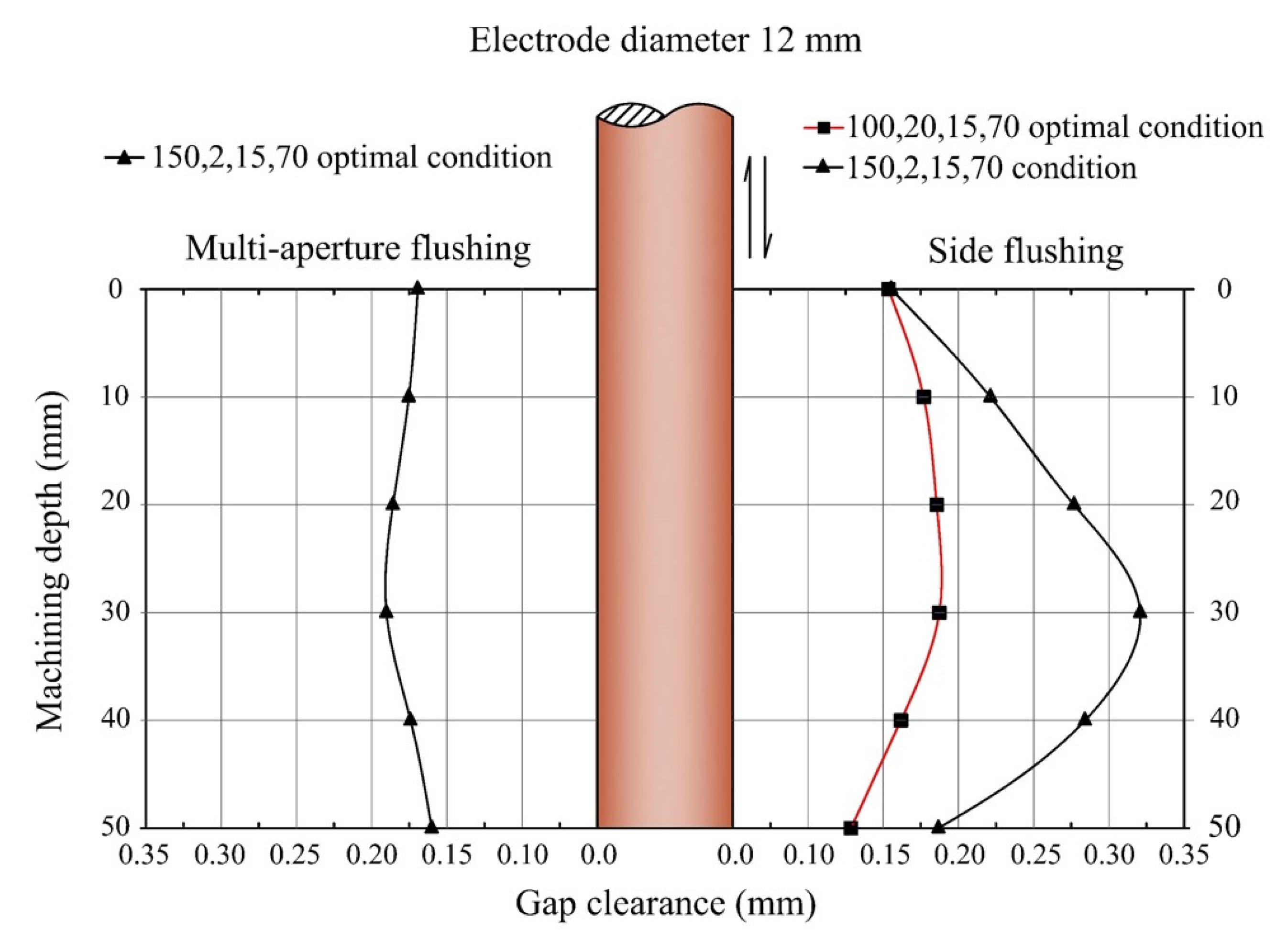
The GC profiles of EDM with side flushing and multi-aperture flushing were characterized at six machining depths: 1, 10, 20, 30, 40, and 50 mm, using a 3D handy scanner and noncontact laser scanning confocal microscope. Figure 11 compares the GC profiles of EDM with side and multi-aperture flushing under their respective optimal machining conditions, given 50 mm machining depth and 12 mm electrode diameter.
The optimal machining condition of EDM with side flushing was 100 µs pulse on-time, 20 µs pulse off-time, 10 A current, and 70 rpm electrode rotation, while that of multi-aperture flushing was 150 µs pulse on-time, 2 µs pulse off-time, 10 A current, and 70 rpm electrode rotation. The GC profiles of both flushing schemes under the optimal machining conditions were almost identical (0.194 and 0.196 mm for EDM with side flushing and multi-aperture flushing). However, the MRR of EDM with multi-aperture flushing was higher with a substantially shorter machining time (Table 13).
Furthermore, given the identical machining condition for side flushing and multi-aperture flushing (150 µs pulse on-time, 2 µs pulse off-time, 10 A current, and 70 rpm electrode rotation), the GC profile of EDM with side flushing exhibited large distortion at 30 mm machining depth (Figure 11). The large bulge (0.319 mm) was attributable to the rapid accumulation of debris as a result of enhanced MRR. The rapid accumulation of debris induced the incidence of a secondary spark, resulting in the GC distortion [37].
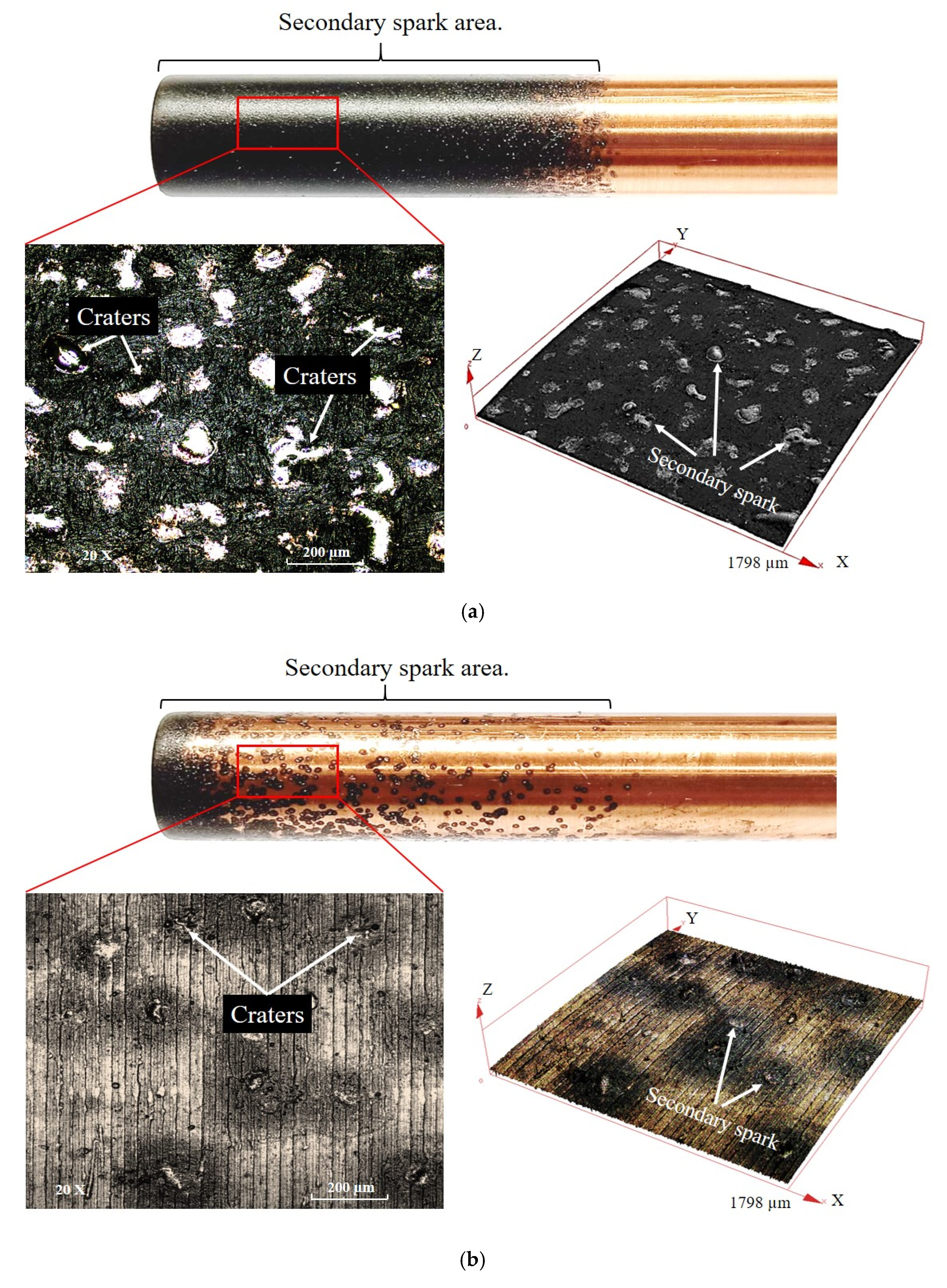
Figure 12a,b shows the effect of a secondary spark on the copper electrode of EDM with side flushing and multi-aperture flushing, respectively. In Figure 12a, large film-like carbon black was formed on the electrode surface, in addition to ubiquitous secondary spark craters. In Figure 12b, substantially smaller film-like carbon black was formed on the tip of the multi-aperture flushing electrode. There were a lower number of secondary spark craters but of larger sizes. The infrequent incidence of a secondary spark was attributable to the efficient removal of debris (and low debris accumulation) as a result of multi-aperture flushing and a faster electrode rotation speed.
3.7. Surface Characteristics of EDM Deep Holes
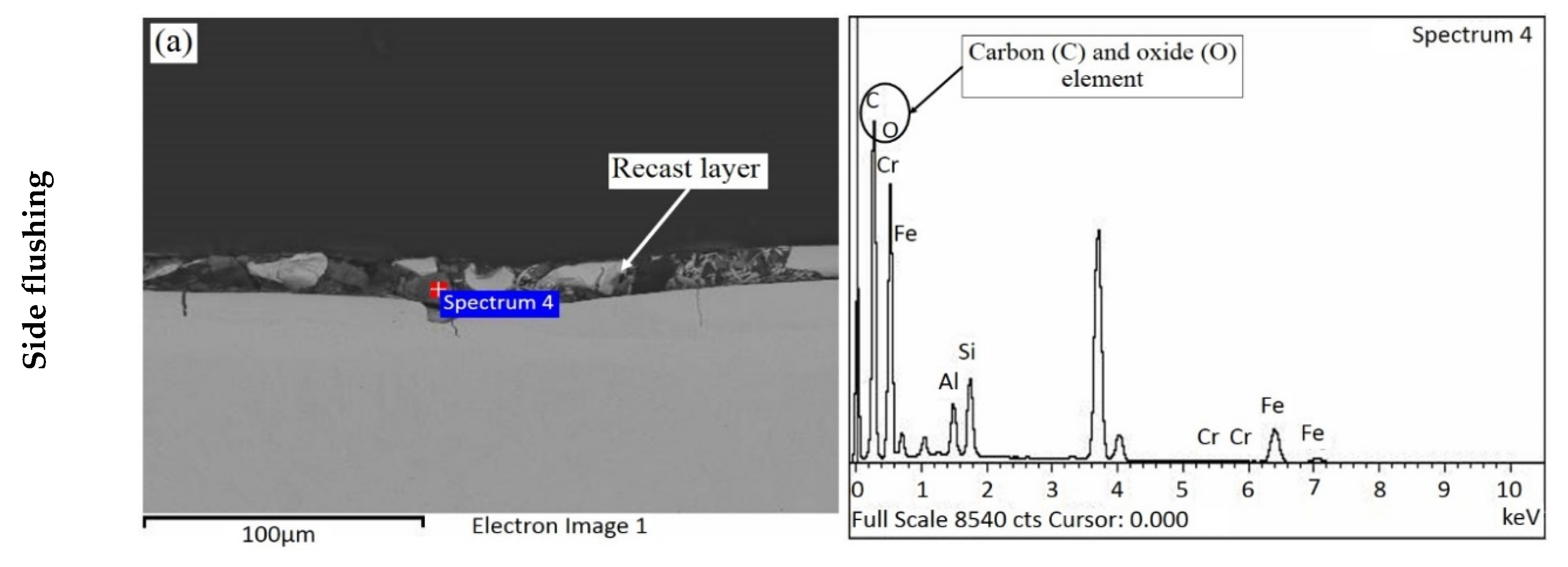
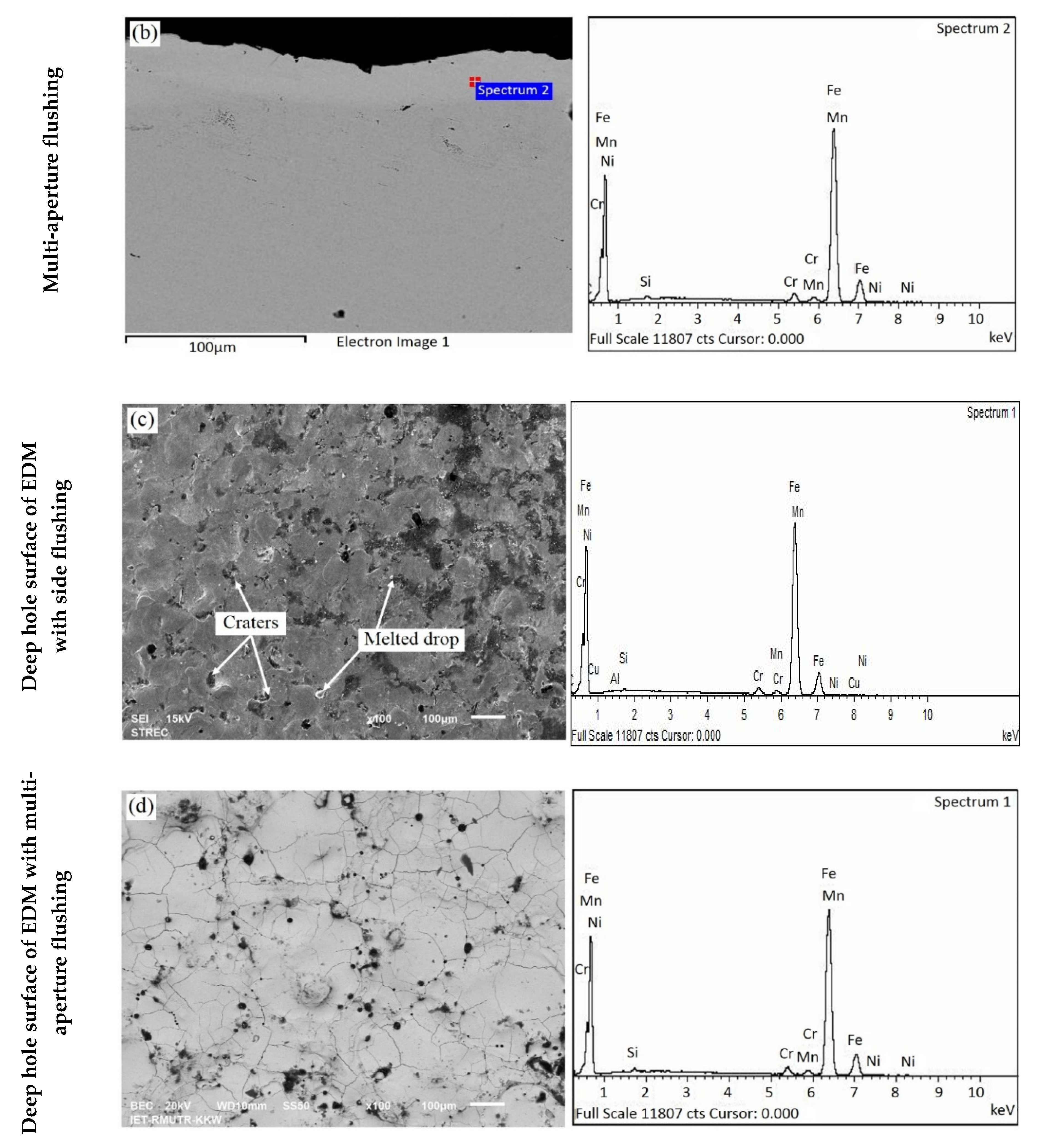
Figure 13a,b shows the cross-sectional SEM images of macro deep holes at 30 mm machining depth using EDM with side flushing and multi-aperture flushing. Figure 13c,d illustrates the deep hole surface of EDM with side flushing and multi-aperture flushing.
In Figure 13a, a recast layer was formed on the workpiece machined with side flushing. The recast layer was the deposition and re-settlement of melted material from the workpiece and electrode and carbon from the dielectric fluid [38]. The EDS compositional analysis showed the presence of carbon (46.31% w/w) and oxide elements (44.66% w/w) in great quantity, as shown in Table 14. The carbon and oxide elements induced the formation of a recast layer on the workpiece. Micro cracks were observed in the workpiece underneath the recast layer. The cracks were primarily attributable to the differential thermal contraction between the higher-temperature recast layer and lower-temperature workpiece [39].
In Figure 13b, no recast layer was detected on the workpiece machined with EDM with multi-aperture flushing. The carbon and ferrous elements were 18.73 and 76.58% w/w without the oxide element, indicating the absence of a recast layer (Table 14). The melted material and debris were efficiently removed with multi-aperture flushing, thereby minimizing re-solidification. The incidence of recast layer formation on the workpiece was substantially reduced with multi-aperture flushing. Nevertheless, micro cracks with shallow penetration depths were observed on the workpiece surface (Figure 13d).
In Figure 13c, the recast layer, melted drops, and spark craters were formed on the workpiece surface. The workpiece surface appeared smooth, as the recast layer mostly concealed the spark craters. In Figure 13d, the micro cracks with shallow penetration depths were observed on the workpiece surface. The shallow micro cracks were attributable to the rapid recovery of dielectric strength in the machining process. The dielectric strength induced strong spark and such high temperatures that the heat could not be drawn quickly enough from the workpiece [40]. In essence, the recast layer formation was substantially reduced by using the multi-aperture flushing. In addition, the cracks on the workpiece surface were shallower than those on the side flushing.
Finally, the results of this research were compared to those of previous research as presented in Table 15. In this research, the proposed multi-aperture flushing improved the MRR and reduced the machining time. The EDM efficiency was also enhanced as the electrode rotation improved the flushing of the dielectric liquid out of the machining gap, resulting in a more uniform GC profile and lower incidence of recast layer. These findings are consistent with those of Kliuev et al. [13]. They reported that insufficient flushing has a tendency to increase the recast layer thickness, and the effect is significant for high aspect ratios of hole diameter and hole depth. Furthermore, better flushing not only enhances the abilities of deep hole drilling, but it also reduces the recast layer. Previous research of Dwivedi et al. [38], which used the same pulse on-time (150 µs), copper electrode, current (15 A), and electrode rotation, found that the average recast layer thickness obtained from the rotary tool EDM process is 40.26 μm, whereas it is 69.03 μm for the stationary tool EDM. The results show that the rotation of the tool reduces the recast layer thickness significantly. In case of the same workpiece material, Dewangan et al. [41] showed that both brass and copper tools show significant influence on affecting the thickness of the react layer formation when using conventional side flushing.
With different workpiece and electrode materials, it was possible to produce different machining characteristics, i.e., MRR, EWR, GC, and surface quality. Zheng et al. [42] used tube-electrode high-speed electrochemical discharge drilling (ECDD) for the machining of nickel-based superalloy. Their findings indicated that the lateral wall of the EDM hole is covered with a recast layer, which is 20–30 μm thickness, but the lateral wall of the hole in ECDD is almost free of a recast layer.
A recast layer produced by EDM is named a white layer because of its color after the etching process. Recast layers exhibit high hardness, good adherence to the bulk material, and good resistance to corrosion. However, the structure of the recast layer is different from that of the base material. Although it is favorable in terms of improved wear resistance, defects such as voids, cracks, and residual stresses result in an overall deterioration of the component mechanical properties [39].
4. Conclusions
This research investigated the effect of machining parameters on MRR, EWR, and GC of macro deep holes of EDM with side flushing and multi-aperture inner flushing. The depth-to-diameter ratio was greater than four (the hole depth of 50 mm and the electrode diameter of 12 mm). The machining parameters included the pulse on-time, pulse off-time, current, and electrode rotation. The following conclusions could be drawn from the experiments:
- The pulse on-time, current, and electrode rotation were positively correlated with the MRR of side-flushing and multi-aperture-flushing EDM. However, a higher MRR induced the rapid accumulation of debris and incidence of secondary spark on the cavity wall, resulting in GC distortion.
- The EWRs of side flushing and multi-aperture flushing were inversely correlated with the pulse on-time and electrode rotation but positively correlated with current.
- Under both flushing schemes, GC was positively correlated with pulse on-time but inversely correlated with pulse off-time, current, and electrode rotation. The electrode rotation played a crucial role in the GC characteristics. Specifically, faster rotational speeds induced centrifugal forces and radial fluid outflow, which enhanced debris removal efficiency. The higher debris removal efficiency resulted in narrower GC and lower EWR.
- Given the trade-off nature of MRR, EWR, and GC, the multi-response desirability function was used to optimize the machining conditions that maximized MRR and minimized EWR and GC, given the desirability weights (w) of 1.0 for MRR, 1.0 for EWR, and 1.2 for GC. The optimal machining condition of EDM with side flushing was 100 µs pulse on-time, 20 µs pulse off-time, 15 A current, and 70 rpm electrode rotation; and that of multi-aperture flushing was 130 µs pulse on-time, 2 µs pulse off-time, 15 A current, and 70 rpm electrode rotation.
- The EDM with multi-aperture flushing, given 50 mm machining depth, achieved a higher MRR and shorter machining time despite greater EWR. Meanwhile, the GC of side flushing and multi-aperture flushing were almost identical.
- The recast layer could be observed on the workpiece machined with side-flushing EDM. However, no recast layer was detected on the workpiece machined with multi-aperture flushing.
- Inefficient flushing of dielectric liquid causes debris to accumulate in the machining gap. The accumulation increases the electrical conductivity of the dielectric liquid, resulting in secondary spark and unsatisfactory machining performance. The proposed multi-aperture flushing improved the MRR and reduced the machining time. The EDM efficiency was also enhanced as the electrode rotation improved the flushing of the dielectric liquid out of the machining gap, resulting in a more uniform GC profile and lower incidence of recast layer. In essence, the multi-aperture flushing EDM effectively removes the debris and improves the performance of macro deep hole machining.
Author Contributions
Conceptualization, S.C., K.K.; Formal analysis, S.C.; Funding acquisition, K.K.; Investigation, S.C., K.K.; Methodology, S.C., K.K.; Project administration, K.K.; Validation, S.C.; Writing—original draft, S.C.; Writing—review and editing, K.K. All authors have read and agreed to the published version of the manuscript.
Funding
This research was financed in part by the Faculty of Engineering, King Mongkut’s Institute of Technology Ladkrabang under grant ID 58601317.
Institutional Review Board Statement
Not applicable.
Informed Consent Statement
Not applicable.
Data Availability Statement
Data sharing not applicable.
Acknowledgments
The authors would like to extend sincere appreciation to the Faculty of Engineering, King Mongkut’s Institute of Technology Ladkrabang, for financial sponsorship; and Rajamangala University of Technology Krungthep for technical support.
Conflicts of Interest
The authors declare no conflict of interest.
References
- Kuppan, P.; Rajadurai, A.; Narayanan, S. Influence of EDM process parameters in deep hole drilling of Inconel 718. Int. J. Adv. Manuf. Technol. 2007, 38, 74–84. [Google Scholar] [CrossRef]
- Maradia, U.; Boccadoro, M.; Stirnimann, J.; Beltrami, I.; Kuster, F.; Wegener, K. Die-sink EDM in Meso-Micro Machining. Procedia CIRP 2012, 1, 166–171. [Google Scholar] [CrossRef]
- Ho, K.H.; Newman, S.T. State of the art electrical discharge machining (EDM). Int. J. Mach. Tools Manuf. 2003, 43, 1287–1300. [Google Scholar] [CrossRef]
- Jamkamon, K.; Janmanee, P. Deep Hole of AISI P20 Mold Steel Material by Electrical Discharge Machining. Appl. Mech. Mater. 2014, 590, 244–248. [Google Scholar]
- Risto, M.; Haas, R.; Munz, M. Optimization of the EDM Drilling Process to Increase the Productivity and Geometrical Accuracy. Procedia CIRP 2016, 42, 537–542. [Google Scholar] [CrossRef]
- Ashkenasi, D.; Kaszemeikat, T.; Mueller, N.; Dietrich, R.; Eichler, H.J.; Illing, G. Laser Trepanning for Industrial Applications. Phys. Preced. 2011, 12, 323–331. [Google Scholar] [CrossRef] [Green Version]
- Diver, C.; Atkinson, J.; Helml, H.J.; Li, L. Micro-EDM drilling of tapered holes for industrial applications. J. Mater. Process. Technol. 2004, 149, 296–303. [Google Scholar] [CrossRef]
- Homri, L.; Goka, E.; Levasseur, G.; Dantan, J.Y. Tolerance analysis-Form defects modeling and simulation by model decomposition and optimization. Comput. Aided Des. 2017, 91, 46–59. [Google Scholar] [CrossRef] [Green Version]
- Uthayakumar, M.; Khan, M.A.; Kumaran, S.T.; Slota, A.; Zajac, J. Machinability of Nickel-Based Superalloy by Abrasive Water Jet Machining. Mater. Manuf. Process. 2016, 31, 1733–1739. [Google Scholar] [CrossRef]
- Murray, J.; Zdebski, D.; Clare, A.T. Workpiece debris deposition on tool electrodes and secondary discharge phenomena in micro-EDM. J. Mater. Process. Technol. 2012, 212, 1537–1547. [Google Scholar] [CrossRef]
- Tanjilul, M.; Ahmed, A.; Kumar, A.S.; Rahman, M. A study on EDM debris particle size and flushing mechanism for efficient debris removal in EDM-drilling of Inconel 718. J. Mater. Process. Technol. 2018, 255, 263–274. [Google Scholar] [CrossRef]
- Cetin, S.; Okada, A.; Uno, Y. Effect of Debris Distribution on Wall Concavity in Deep-Hole EDM. JSME Int. J. Ser. C Mech. Syst. Mach. Elem. Manuf. 2004, 47, 553–559. [Google Scholar] [CrossRef] [Green Version]
- Kliuev, M.; Baumgart, C.; Büttner, H.; Wegener, K. Flushing Velocity Observations and Analysis during EDM Drilling. Procedia CIRP 2018, 77, 590–593. [Google Scholar] [CrossRef]
- Liao, Y.S.; Liang, F.Y.; Tsai, Y.Y. A Study of the Debris Exclusion for Various Cross-section Electrodes in Linear Motor Equipped Deep Cavity EDM Process. Procedia CIRP 2018, 68, 660–665. [Google Scholar] [CrossRef]
- Gadeschi, G.B.; Schneider, S.; Mohammadnejad, M.; Meinke, M.; Klink, A.; Schröder, W.; Klocke, F. Numerical Analysis of Flushing-Induced Thermal Cooling Including Debris Transport in Electrical Discharge Machining (EDM). Procedia CIRP 2017, 58, 116–121. [Google Scholar] [CrossRef]
- Mathai, V.; Dave, H.; Desai, K. Effect of Flushing Strategies on Responses during Planetary EDM of Ti-6Al-4V. In Proceedings of the International Conference on Precision, Meso, Micro and Nano Engineering (COPEN 9), Indian Institute of Technology, Bombay, India, 10–12 December, 2015. [Google Scholar]
- Goiogana, M.; Elkaseer, A. Self-Flushing in EDM Drilling of Ti6Al4V Using Rotating Shaped Electrodes. Materials 2019, 12, 989. [Google Scholar] [CrossRef] [Green Version]
- Kumar, R.; Singh, I. A modified electrode design for improving process performance of electric discharge drilling. J. Mater. Process. Technol. 2019, 264, 211–219. [Google Scholar] [CrossRef]
- Li, L.; Gu, L.; Xi, X.; Zhao, W. Influence of flushing on performance of EDM with bunched electrode. Int. J. Adv. Manuf. Technol. 2012, 58, 187–194. [Google Scholar] [CrossRef]
- Barenji, R.V.; Pourasl, H.H.; Khojastehnezhad, V.M. Electrical discharge machining of the AISI D6 tool steel: Prediction and modeling of the material removal rate and tool wear ratio. Precis. Eng. 2016, 45, 435–444. [Google Scholar] [CrossRef]
- Lin, Y.C.; Tsao, C.C.; Hsu, C.Y.; Hung, S.K.; Wen, D.C. Evaluation of the characteristics of the microelectrical discharge machining process using response surface methodology based on the central composite design. Int. J. Adv. Manuf. Technol. 2011, 62, 1013–1023. [Google Scholar] [CrossRef]
- Sultan, T.; Kumar, A.; Gupta, R.D. Material Removal Rate, Electrode Wear Rate, and Surface Roughness Evaluation in Die Sinking EDM with Hollow Tool through Response Surface Methodology. Int. J. Manuf. Eng. 2014, 2014, 1–16. [Google Scholar] [CrossRef] [Green Version]
- Gopalakannan, D.S. Optimization of machining parameters for EDM operations based on central composite design and desirability approach. J. Mech. Sci. Technol. 2014, 28, 1045–1053. [Google Scholar] [CrossRef]
- Habib, S.S. Study of the parameters in electrical discharge machining through response surface methodology approach. Appl. Math. Model. 2009, 33, 4397–4407. [Google Scholar] [CrossRef] [Green Version]
- Hourmand, M.; Farahany, S.; Sarhan, A.A.D.; Noordin, M.Y. Investigating the electrical discharge machining (EDM) parameter effects on Al-Mg2Si metal matrix composite (MMC) for high material removal rate (MRR) and less EWR–RSM approach. Int. J. Adv. Manuf. Technol. 2014, 77, 831–838. [Google Scholar] [CrossRef]
- Liu, Q.; Zhang, Q.; Zhang, M.; Zhang, J. Review of size effects in micro electrical discharge machining. Precis. Eng. 2016, 44, 29–40. [Google Scholar] [CrossRef]
- Plaza, S.; Sanchez, J.A.; Perez, E.; Gil, R.; Izquierdo, B.; Ortega, N.; Pombo, I. Experimental study on micro EDM-drilling of Ti6Al4V using helical electrode. Precis. Eng. 2014, 38, 821–827. [Google Scholar] [CrossRef]
- Nakagawa, T.; Yuzawa, T.; Sampei, M.; Hirata, A. Improvement in machining speed with working gap control in EDM milling. Precis. Eng. 2017, 47, 303–310. [Google Scholar] [CrossRef]
- Zhang, S.; Zhang, W.; Liu, Y.; Ma, F.; Su, C.; Sha, Z. Study on the Gap Flow Simulation in EDM Small Hole Machining with Ti Alloy. Adv. Mater. Sci. Eng. 2017, 2017, 1–23. [Google Scholar]
- Chuvaree, S.; Kanlayasiri, K. An investigation on dimensional accuracy of EDM deep hole using multi-hole interior flushing electrode. MATEC Web Conf. 2018, 192, 01029. [Google Scholar] [CrossRef]
- Chuvaree, S.; Kanlayasiri, K. Improving the performance of EDM deep hole using multi-hole interior flushing electrode. IOP Conf. Ser. Mater. Sci. Eng. 2018, 361, 012013. [Google Scholar] [CrossRef]
- Park, S.H.; Park, J.O. Simultaneous Optimization of Multiple Responses Using a Weighted Desirability Function. In Quality Improvement through Statistical Methods; Abraham, B., Ed.; Birkhäuser Boston: Boston, MA, USA, 1998; pp. 299–311. [Google Scholar]
- Wang, J.; He, Z.; Oh, J.; Park, S. Multi-Response Robust Optimization Using Desirability Function. In Proceedings of the 2008 IEEE Symposium on Advanced Management of Information for Globalized Enterprises (AMIGE), Tianjin, China, 28–29 September 2008; pp. 1–3. [Google Scholar]
- Naveen Beri, H.P.; Kumar, A. To Study the Effect of Polarity and Current during Electric Discharge Machining of Inconel 718 with CuW Powder Metallurgy Electrode. In Proceedings of the National Conference on Trends and Advances in Mechanical Engineering, Faridabad, Haryana, India, 19–20 October 2012; pp. 476–481. [Google Scholar]
- Mohri, N.; Suzuki, M.; Furuya, M.; Saito, N.; Kobayashi, A. Electrode Wear Process in Electrical Discharge Machinings. Cirp Ann. 1995, 44, 165–168. [Google Scholar] [CrossRef]
- Madiha, R.; Nadeem, A.M.; Naveed, A.; Abdulrahman, M.A.; Amjad, H. EDM of D2 Steel: Performance Comparison of EDM die Sinking Electrode Designs. Appl. Sci. 2020, 10, 7411. [Google Scholar]
- Ekmekci, B.; Sayar, A. Debris and consequences in micro electric discharge machining of micro-holes. Int. J. Mach. Tools Manuf. 2013, 65, 58–67. [Google Scholar] [CrossRef]
- Dwivedi, A.P.; Choudhury, S.K. Estimation of Recast Layer Thickness in Rotary Tool EDM Process for Machining AISI D3 Tool Steel. Mater. Today Proc. 2017, 4, 10816–10822. [Google Scholar] [CrossRef]
- Ekmekci, B. White Layer Composition, Heat Treatment, and Crack Formation in Electric Discharge Machining Process. Metall. Mater. Trans. B 2009, 40, 70–81. [Google Scholar] [CrossRef]
- Yilmaz, O.; Okka, M.A. Effect of single and multi-channel electrodes application on EDM fast hole drilling performance. Int. J. Adv. Manuf. Technol. 2010, 51, 185–194. [Google Scholar] [CrossRef]
- Dewangan, S.; Biswas, C.K.; Gangopadhyay, S. Influence of Different Tool Electrode Materials on EDMed Surface Integrity of AISI P20 Tool Steel. Mater. Manuf. Process. 2014, 29, 1387–1394. [Google Scholar] [CrossRef]
- Zheng, Y.X.; Zhang, Y.; Ding, F. An electrochemical discharge drilling method of small deep holes. Int. J. Adv. Manuf. Technol. 2018, 95, 3037–3044. [Google Scholar]
Figure 1.
Gap clearance distortion: (a) Reverse taper, (b) V-shaped taper, (c) barrel taper.

Figure 2.
(a) Schematics of electrical discharge machining (EDM) macro deep hole experimental setup (conventional side flushing and multi-aperture flushing), (b) multi-aperture inner flushing copper electrode (electrode prototype).
Figure 2.
(a) Schematics of electrical discharge machining (EDM) macro deep hole experimental setup (conventional side flushing and multi-aperture flushing), (b) multi-aperture inner flushing copper electrode (electrode prototype).

Figure 3.
The gap clearance profiles: (a) dismembered AISI P20 tool steel workpieces, (b) maximum gap clearance (GC) distortion measurement, (c) locations of GC distortion measurement.
Figure 3.
The gap clearance profiles: (a) dismembered AISI P20 tool steel workpieces, (b) maximum gap clearance (GC) distortion measurement, (c) locations of GC distortion measurement.

Figure 4.
MRRsf as a function of pulse on-time and current, given pulse off-time = 10 µs and electrode rotation = 35 rpm.
Figure 4.
MRRsf as a function of pulse on-time and current, given pulse off-time = 10 µs and electrode rotation = 35 rpm.

Figure 5.
MRRmf as a function of (a) pulse on-time and current, given pulse off-time = 10 µs and electrode rotation = 35 rpm, (b) pulse off-time and electrode rotation, given pulse on-time = 100 µs and current = 12 A.
Figure 5.
MRRmf as a function of (a) pulse on-time and current, given pulse off-time = 10 µs and electrode rotation = 35 rpm, (b) pulse off-time and electrode rotation, given pulse on-time = 100 µs and current = 12 A.

Figure 6.
EWRsf as a function of: (a) pulse on-time and current, given pulse off-time = 10 µs and electrode rotation = 35 rpm, (b) pulse off-time and current, given pulse on-time = 100 µs and current = 12 A.
Figure 6.
EWRsf as a function of: (a) pulse on-time and current, given pulse off-time = 10 µs and electrode rotation = 35 rpm, (b) pulse off-time and current, given pulse on-time = 100 µs and current = 12 A.

Figure 7.
Film-like carbon black on copper electrode: (a) SEM micrograph at 40 mm depth, (b) energy-dispersive spectrometry (EDS) compositional analysis.
Figure 7.
Film-like carbon black on copper electrode: (a) SEM micrograph at 40 mm depth, (b) energy-dispersive spectrometry (EDS) compositional analysis.

Figure 8.
EWRmf as a function of (a) pulse on-time and electrode rotation, given pulse off-time = 10 µs and current 12 A, (b) pulse off-time and electrode rotation, given pulse on-time = 100 µs and current = 12 A.
Figure 8.
EWRmf as a function of (a) pulse on-time and electrode rotation, given pulse off-time = 10 µs and current 12 A, (b) pulse off-time and electrode rotation, given pulse on-time = 100 µs and current = 12 A.

Figure 9.
GCsf as a function of (a) pulse on-time and current, given pulse off-time = 10 µs and electrode rotation = 35 rpm, (b) pulse off-time and electrode rotation, given pulse on-time = 100 µs and current = 12 A, (c) current and electrode rotation, given pulse on-time = 100 µs, and pulse off-time = 10 µs.


Figure 10.
GCmf as a function of (a) pulse on-time and pulse off-time, given current = 12 A and electrode rotation = 35 rpm, (b) pulse on-time and current, given pulse off-time = 10 µs and electrode rotation = 35 rpm, (c) pulse on-time and electrode rotation, given pulse off-time = 10 µs and current = 12 A.

Figure 11.
GC profiles of EDM with side flushing and multi-aperture flushing.

Figure 12.
Craters and secondary sparks on the electrode: (a) EDM with side flushing, (b) EDM with multi-aperture flushing.
Figure 12.
Craters and secondary sparks on the electrode: (a) EDM with side flushing, (b) EDM with multi-aperture flushing.

Figure 13.
SEM images and EDS compositional analysis at 30 mm machining depth: (a) cross-sectional view of side flushing, (b) cross-sectional view of multi-aperture flushing, (c) deep hole surface of side flushing, (d) deep hole surface of multi-aperture flushing.
Figure 13.
SEM images and EDS compositional analysis at 30 mm machining depth: (a) cross-sectional view of side flushing, (b) cross-sectional view of multi-aperture flushing, (c) deep hole surface of side flushing, (d) deep hole surface of multi-aperture flushing.


Table 1.
Chemical composition of AISI P20 plastic mold steel.
| Element | C | Mn | Cr | Mo | Si | S | Fe |
|---|---|---|---|---|---|---|---|
| wt % | 0.28 | 0.6 | 2.0 | 0.5 | 0.2 | <0.03 | Bal. |
Table 2.
Design scheme of machining parameters and their levels.
| Factor Symbol/Notation | Parameters | Unit | Levels | ||
|---|---|---|---|---|---|
| Low (−1) | Center (0) | High (+1) | |||
| A (ton) | Pulse on-time | µs | 50 | 100 | 150 |
| B (toff) | Pulse off-time | µs | 2 | 10 | 20 |
| C (I) | Current | A | 9 | 12 | 15 |
| D (N) | Electrode rotation | rpm | 0 | 35 | 70 |
Table 3.
The ANOVA of the reduced regression model for material removal rate (MRR) of EDM with side flushing.
Table 3.
The ANOVA of the reduced regression model for material removal rate (MRR) of EDM with side flushing.
| Source | Sum of Squares | Degree of Freedom | Mean Square | F-Value | p-Value | Coefficient |
|---|---|---|---|---|---|---|
| Model | 364.13 | 4 | 91.033 | 37.80 | <0.001 | 22.0391 |
| A | 55.86 | 1 | 55.859 | 23.19 | <0.001 | −0.0619 |
| C | 269.82 | 1 | 269.816 | 112.02 | <0.001 | −3.2590 |
| C2 | 14.85 | 1 | 14.846 | 6.16 | 0.020 | 0.1558 |
| AC | 23.61 | 1 | 23.612 | 9.80 | 0.004 | 0.0081 |
| Error | 62.62 | 26 | 2.409 | |||
| Total | 426.76 | 30 | ||||
| R2 = 85.33% | R2 (adj) = 83.07% |
Table 4.
The ANOVA of the reduced regression model for the material removal rate (MRR) of EDM with multi-aperture flushing.
Table 4.
The ANOVA of the reduced regression model for the material removal rate (MRR) of EDM with multi-aperture flushing.
| Source | Sum of Squares | Degree of Freedom | Mean Square | F-Value | p-Value | Coefficient |
|---|---|---|---|---|---|---|
| Model | 295.459 | 5 | 59.092 | 62.89 | <0.001 | 8.90 |
| A | 79.632 | 1 | 79.632 | 84.76 | <0.001 | −0.0805 |
| B | 15.127 | 1 | 15.127 | 16.10 | <0.001 | −0.1016 |
| C | 156.722 | 1 | 156.722 | 166.81 | <0.001 | −0.038 |
| D | 6.438 | 1 | 6.438 | 6.85 | 0.015 | 0.01709 |
| AC | 37.540 | 1 | 37.540 | 39.96 | <0.001 | 0.01021 |
| Error | 23.488 | 25 | 0.940 | |||
| Total | 318.948 | 30 | ||||
| R2 = 92.64% | R2 (adj) = 91.16% |
Table 5.
The ANOVA of the reduced regression model for electrode wear ratio (EWR) of EDM with side flushing.
Table 5.
The ANOVA of the reduced regression model for electrode wear ratio (EWR) of EDM with side flushing.
| Source | Sum of Squares | Degree of Freedom | Mean Square | F-Value | p-Value | Coefficient |
|---|---|---|---|---|---|---|
| Model | 11.8348 | 7 | 1.69069 | 45.31 | <0.001 | 0.887 |
| A | 8.5257 | 1 | 8.52570 | 228.48 | <0.001 | −0.0320 |
| B | 0.0730 | 1 | 0.07301 | 1.96 | 0.175 | 0.0423 |
| C | 1.3916 | 1 | 1.39160 | 37.29 | <0.001 | 0.2355 |
| D | 0.2554 | 1 | 0.25537 | 6.84 | 0.015 | −0.0034 |
| A2 | 1.0609 | 1 | 1.06094 | 28.43 | <0.001 | 0.00015 |
| AC | 0.3425 | 1 | 0.34252 | 9.18 | 0.006 | −0.000975 |
| BC | 0.1979 | 1 | 0.19793 | 5.30 | 0.031 | −0.00412 |
| Error | 0.8582 | 23 | 0.03731 | |||
| Total | 12.6930 | 30 | ||||
| R2 = 93.24% | R2 (adj) = 91.18% |
Table 6.
The ANOVA of the reduced regression model for electrode wear ratio (EWR) of EDM with multi-aperture flushing.
Table 6.
The ANOVA of the reduced regression model for electrode wear ratio (EWR) of EDM with multi-aperture flushing.
| Source | Sum of Squares | Degree of Freedom | Mean Square | F-Value | p-Value | Coefficient |
|---|---|---|---|---|---|---|
| model | 227.120 | 9 | 25.234 | 32.82 | <0.001 | 14.80 |
| A | 182.049 | 1 | 182.049 | 176.89 | <0.001 | −0.2181 |
| B | 0.343 | 1 | 0.343 | 0.330 | 0.570 | 0.190 |
| C | 3.312 | 1 | 3.312 | 3.220 | 0.087 | 0.219 |
| D | 1.110 | 1 | 1.110 | 1.08 | 0.311 | −0.0843 |
| A2 | 26.896 | 1 | 26.896 | 26.13 | <0.001 | 0.000756 |
| AD | 0.420 | 1 | 0.420 | 0.410 | 0.530 | 0.000093 |
| BC | 4.560 | 1 | 4.560 | 4.83 | 0.048 | −0.01976 |
| BD | 4.976 | 1 | 4.976 | 3.78 | 0.039 | 0.001769 |
| CD | 2.874 | 1 | 2.874 | 2.79 | 0.110 | 0.00404 |
| Error | 32.881 | 21 | 1.029 | |||
| Total | 248.715 | 30 | ||||
| R2 = 91.31% | R2 (adj) = 87.59% |
Table 7.
The ANOVA of the reduced regression model for gap clearance (GC) of EDM with side flushing.
Table 7.
The ANOVA of the reduced regression model for gap clearance (GC) of EDM with side flushing.
| Source | Sum of Squares | Degree of Freedom | Mean Square | F-Value | p-Value | Coefficient |
|---|---|---|---|---|---|---|
| Model | 0.039611 | 6 | 0.006602 | 37.05 | <0.001 | 0.0843 |
| A | 0.028481 | 1 | 0.028481 | 159.84 | <0.001 | 0.000398 |
| B | 0.000019 | 1 | 0.000019 | 0.10 | 0.750 | 0.000434 |
| C | 0.008889 | 1 | 0.008889 | 49.89 | <0.001 | 0.005006 |
| D | <0.00001 | 1 | <0.00001 | <0.001 | 0.999 | 0.0006 |
| BD | 0.001246 | 1 | 0.001246 | 6.99 | 0.014 | −0.000014 |
| CD | 0.00097 | 1 | 0.000977 | 5.48 | 0.028 | −0.000037 |
| Error | 0.004276 | 24 | 0.000178 | |||
| Total | 0.043888 | 30 | ||||
| R2 = 90.26% | R2 (adj)= 87.82% |
Table 8.
The ANOVA of the reduced regression model for gap clearance (GC) of EDM with multi-aperture flushing.
Table 8.
The ANOVA of the reduced regression model for gap clearance (GC) of EDM with multi-aperture flushing.
| Source | Sum of Squares | Degree of Freedom | Mean Square | F-Value | p-Value | Coefficient |
|---|---|---|---|---|---|---|
| model | 0.010194 | 8 | 0.001699 | 13.84 | <0.001 | 0.1758 |
| A | 0.005277 | 1 | 0.005277 | 43.00 | <0.001 | −0.000449 |
| B | 0.000038 | 1 | 0.000038 | 0.31 | 0.585 | −0.002395 |
| C | 0.001217 | 1 | 0.001217 | 9.92 | 0.004 | −0.00141 |
| D | 0.001503 | 1 | 0.001503 | 12.25 | 0.002 | −0.00045 |
| D2 | 0.000006 | 1 | 0.000006 | 0.22 | 0.829 | 0.000001 |
| AB | 0.001616 | 1 | 0.001616 | 13.16 | 0.001 | 0.000022 |
| AC | 0.000619 | 1 | 0.000619 | 5.04 | 0.034 | 0.000041 |
| AD | 0.000093 | 1 | 0.000093 | 0.85 | 0.407 | 0.000001 |
| Error | 0.002945 | 22 | 0.000123 | - | - | - |
| Total | 0.013139 | 30 | - | - | - | - |
| R2 = 78.34% | R2 (adj) = 70.46% |
Table 9.
Criteria for multi-response optimization of EDM with side flushing.
| Output Response | Goal | Lower (Li) | Upper (Ui) | Weight (w) | Importance |
|---|---|---|---|---|---|
| Pulse on-time (µs) | In range | 50 | 150 | 1 | - |
| Pulse off-time (µs) | In range | 2 | 20 | 1 | - |
| Current (A) | In range | 9 | 15 | 1 | - |
| Electrode rotation (rpm) | In range | 0 | 70 | 1 | - |
| GC (mm) | Minimum | 0.1545 | 0.238 | 1.2 | 1 |
| EWR (%) | Minimum | 0.0840 | 3.056 | 1.0 | 1 |
| MRR (mm3/min) | Maximum | 4.636 | 18.9650 | 1.0 | 1 |
Table 10.
Criteria for multi-response optimization of EDM with multi-aperture flushing.
| Output Response | Goal | Lower (Li) | Upper (Ui) | Weight (w) | Importance |
|---|---|---|---|---|---|
| Pulse on-time (µs) | In range | 50 | 150 | 1 | - |
| Pulse off-time (µs) | In range | 2 | 20 | 1 | - |
| Current (A) | In range | 9 | 15 | 1 | - |
| Electrode rotation (rpm) | In range | 0 | 70 | 1 | - |
| GC (mm) | Minimum | 0.1125 | 0.211 | 1.2 | 1 |
| EWR (%) | Minimum | 0.3690 | 8.742 | 1.0 | 1 |
| MRR (mm3/min) | Maximum | 7.366 | 21.660 | 1.0 | 1 |
Table 11.
The response surface methodology predicted and experimental results under the optimal machining condition of EDM with side flushing.
Table 11.
The response surface methodology predicted and experimental results under the optimal machining condition of EDM with side flushing.
| Exp. No. | Parameters | Material Removal Rate (mm3/min) | Electrode Wear Ratio (%) | Gap Clearance (mm) | |||||||||
|---|---|---|---|---|---|---|---|---|---|---|---|---|---|
| Pulse on-Time (µs) | Pulse off-Time (µs) | Current (A) | Electrode Rotation (rpm) | EXP. | Prediction | Error (%) | EXP. | Prediction | Error (%) | EXP. | Prediction | Error (%) | |
| 1 | 100 | 20 | 15 | 70 | 15.100 | 14.166 | 6.59 | 0.620 | 0.622 | −0.32 | 0.200 | 0.191 | 4.71 |
| 2 | 100 | 20 | 15 | 70 | 15.352 | 14.166 | 8.37 | 0.675 | 0.622 | 8.52 | 0.204 | 0.191 | 6.80 |
| 3 | 100 | 20 | 15 | 70 | 14.851 | 14.166 | 4.83 | 0.639 | 0.622 | 2.73 | 0.194 | 0.191 | 1.57 |
| 4 | 100 | 20 | 15 | 70 | 14.961 | 14.166 | 5.61 | 0.660 | 0.622 | 6.10 | 0.197 | 0.191 | 3.14 |
| 5 | 100 | 20 | 15 | 70 | 15.729 | 14.166 | 11.03 | 0.581 | 0.622 | −6.59 | 0.211 | 0.191 | 10.47 |
| Average | 15.200 | 7.286 | 0.635 | 4.856 | 0.201 | 5.338 | |||||||
Table 12.
The response surface methodology predicted and experimental results under the optimal machining condition of EDM with multi-aperture flushing.
Table 12.
The response surface methodology predicted and experimental results under the optimal machining condition of EDM with multi-aperture flushing.
| Exp. No. | Parameters | Material Removal Rate (mm3/min) | Electrode Wear Ratio (%) | Gap Clearance (mm) | |||||||||
|---|---|---|---|---|---|---|---|---|---|---|---|---|---|
| Pulse on-Time (µs) | Pulse off-Time (µs) | Current (A) | Electrode Rotation (rpm) | EXP. | Prediction | Error (%) | EXP. | Prediction | Error (%) | EXP. | Prediction | Error (%) | |
| 1 | 150 | 2 | 15 | 70 | 21.660 | 20.236 | 7.036 | 1.588 | 1.737 | −8.578 | 0.196 | 0.169 | 15.90 |
| 2 | 150 | 2 | 15 | 70 | 21.421 | 20.236 | 5.855 | 1.637 | 1.737 | −5.757 | 0.201 | 0.169 | 18.86 |
| 3 | 150 | 2 | 15 | 70 | 20.806 | 20.236 | 2.816 | 1.772 | 1.737 | −2.014 | 0.206 | 0.169 | 21.80 |
| 4 | 150 | 2 | 15 | 70 | 21.159 | 20.236 | 4.561 | 1.591 | 1.737 | −8.405 | 0.205 | 0.169 | 21.23 |
| 5 | 150 | 2 | 15 | 70 | 20.983 | 20.236 | 3.691 | 1.602 | 1.737 | −7.772 | 0.199 | 0.169 | 17.68 |
| Average | 21.206 | 4.792 | 1.638 | 6.5052 | 0.201 | 19.094 | |||||||
Table 13.
Optimal conditions and machining performance of EDM with side and multi-aperture flushing.
Table 13.
Optimal conditions and machining performance of EDM with side and multi-aperture flushing.
| Flushing Scheme | Optimal Machining Parameters | MRR (mm3/min) | EWR (%) | GC (mm) | Machining Time (min) | |||
|---|---|---|---|---|---|---|---|---|
| Pulse on-Time (µs) | Pulse off-Time (µs) | Current(A) | Electrode Rotation (rpm) | |||||
| Side flushing | 100 | 20 | 15 | 70 | 15.729 | 0.581 | 0.194 | 339.01 |
| Multi-aperture flushing | 150 | 2 | 15 | 70 | 21.660 | 1.588 | 0.196 | 250.53 |
Table 14.
EDS analysis of cross-sectional view and top view of deep hole surface of EDM with side and multi-aperture flushing at 30 mm machining depth.
Table 14.
EDS analysis of cross-sectional view and top view of deep hole surface of EDM with side and multi-aperture flushing at 30 mm machining depth.
| Element | Cross-Sectional View of Side Flushing | Cross-Sectional View of Multi-Aperture Flushing | Top View of EDM with Side Flushing | Top View of EDM with Multi-Aperture Flushing | ||||
|---|---|---|---|---|---|---|---|---|
| Weight % | Atomic % | Weight % | Atomic % | Weight % | Atomic % | Weight % | Atomic % | |
| C | 46.31 | 56.03 | 18.73 | 51.57 | 16.44 | 47.61 | 16.81 | 48.33 |
| O | 44.66 | 40.56 | - | - | - | - | - | - |
| Al | 1.54 | 0.83 | - | - | 0.18 | 0.23 | - | - |
| Si | 2.44 | 1.26 | 0.42 | 0.49 | 0.31 | 0.39 | 0.30 | 0.37 |
| Cr | 0.12 | 0.03 | 1.85 | 1.17 | 1.66 | 1.11 | 1.88 | 1.25 |
| Fe | 4.94 | 1.28 | 76.58 | 45.35 | 78.86 | 49.11 | 78.62 | 48.46 |
| Ni | - | - | 0.89 | 0.50 | 1.07 | 0.63 | 0.83 | 0.49 |
| Mn | - | - | 1.40 | 0.84 | 1.29 | 0.82 | 1.34 | 0.83 |
| Cu | - | - | 0.13 | 0.07 | 0.20 | 0.11 | 0.22 | 0.12 |
| Total | 100.00 | 100.00 | 100.00 | 100.00 | ||||
Table 15.
Comparison of the machining characteristics on the recast layer.
| Ref. | Electrode/Materials /Process | Parameters | Key Findings |
|---|---|---|---|
| This research | -Cu-electrode -AISI P20 -Side and multi-aperture inner flushing (Ø 12 mm) | Current (9, 12, 15 A) Pulse on-time (50, 100, and 150 µs) Pulse off-time (2,10, and 20 µs) Electrode rotation (0–70 rpm) Polarity (electrode +) Hole type (Blind) | The recast layer could be observed on the workpiece machined with side flushing EDM. However, no recast layer was detected on the workpiece machined with multi-aperture flushing. |
| [13] | -Cu-electrode -Inconel 718 -Single and multi-channels- electrode -CFD simulations | Pulse on-time (32 µs) Pulse off-time (15 µs) Polarity (electrode) Voltage (120 V) Hole type (Blind) | Insufficient flushing has a tendency to increase the recast layer thickness. The effect is significant for high aspect ratios between hole diameter and hole depth. |
| [38] | -Solid Cu-electrode -AISI D3-Stationary tool and rotary tool (Ø10 mm) | Current (10, 15, 20, and 25 A) Pulse on-time (150 µs) Pulse off-time (58.33 µs) Polarity (+) Tool rotary (0–1000 rpm) Hole type (Blind) | The average recast layer thickness obtained from the rotary tool EDM process is 40.26 μm whereas it is 69.03 μm for the stationary tool EDM. The results show that the rotation of the tool reduces the recast layer thickness significantly. |
| [41] | -Solid Copper-electrode, brass-electrode -AISI P20 -side flushing (Ø12 mm) | Current (2,4,6, and 8 A) Pulse on-time (50,80, and 100 µs) Duty cycle (75,85, and 95%) Polarity (Workpiece +, −) Hole type (Blind) | Both brass and copper tool show significant influence on thickness of the react layer formation. |
| [42] | -Metal tube -Nickel-based- super alloy -Tube-electrode high speed electrochemical discharge drilling (ECDD) | Pulse on-time (20 µs) Pulse off-time (12 µs) Polarity (electrode −) Voltage (80 V) | The lateral wall of EDM hole is covered with a recast layer which is 20–30-μm thick, but the lateral wall of the hole in ECDD is almost free of the recast layer. |
Publisher’s Note: MDPI stays neutral with regard to jurisdictional claims in published maps and institutional affiliations. |
© 2021 by the authors. Licensee MDPI, Basel, Switzerland. This article is an open access article distributed under the terms and conditions of the Creative Commons Attribution (CC BY) license (http://creativecommons.org/licenses/by/4.0/).
Share and Cite
MDPI and ACS Style
Chuvaree, S.; Kanlayasiri, K. Effects of Side Flushing and Multi-Aperture Inner Flushing on Characteristics of Electrical Discharge Machining Macro Deep Holes. Metals 2021, 11, 148. https://0-doi-org.brum.beds.ac.uk/10.3390/met11010148
AMA Style
Chuvaree S, Kanlayasiri K. Effects of Side Flushing and Multi-Aperture Inner Flushing on Characteristics of Electrical Discharge Machining Macro Deep Holes. Metals. 2021; 11(1):148. https://0-doi-org.brum.beds.ac.uk/10.3390/met11010148
Chicago/Turabian StyleChuvaree, Suppawat, and Kannachai Kanlayasiri. 2021. "Effects of Side Flushing and Multi-Aperture Inner Flushing on Characteristics of Electrical Discharge Machining Macro Deep Holes" Metals 11, no. 1: 148. https://0-doi-org.brum.beds.ac.uk/10.3390/met11010148
Note that from the first issue of 2016, this journal uses article numbers instead of page numbers. See further details here.