Article

A Novel Pyrometallurgical Recycling Process for Lithium-Ion Batteries and Its Application to the Recycling of LCO and LFP

by
Alexandra Holzer
*,
Stefan Windisch-Kern
,
Christoph Ponak
and
Harald Raupenstrauch
Chair of Thermal Processing Technology, Montanuniversitaet Leoben, Franz-Josef-Strasse 18, 8700 Leoben, Austria
*
Author to whom correspondence should be addressed.
Submission received: 11 December 2020 / Revised: 31 December 2020 / Accepted: 11 January 2021 / Published: 14 January 2021

Abstract

:
The bottleneck of recycling chains for spent lithium-ion batteries (LIBs) is the recovery of valuable metals from the black matter that remains after dismantling and deactivation in pre‑treatment processes, which has to be treated in a subsequent step with pyrometallurgical and/or hydrometallurgical methods. In the course of this paper, investigations in a heating microscope were conducted to determine the high-temperature behavior of the cathode materials lithium cobalt oxide (LCO—chem., LiCoO2) and lithium iron phosphate (LFP—chem., LiFePO4) from LIB with carbon addition. For the purpose of continuous process development of a novel pyrometallurgical recycling process and adaptation of this to the requirements of the LIB material, two different reactor designs were examined. When treating LCO in an Al2O3 crucible, lithium could be removed at a rate of 76% via the gas stream, which is directly and purely available for further processing. In contrast, a removal rate of lithium of up to 97% was achieved in an MgO crucible. In addition, the basic capability of the concept for the treatment of LFP was investigated whereby a phosphorus removal rate of 64% with a simultaneous lithium removal rate of 68% was observed.

1. Introduction

The development of lithium-ion batteries (LIBs) has experienced an enormous upswing in recent years, which is, in addition to portable devices, mainly due to the steadily increasing demand in the electric vehicle (EV) sector. According to forecasts, this trend will continue in the coming years [1,2]. Further prognoses predict that sales of LIBs are expected to increase from 160 GWh in 2018 to over 1.2 TWh in 2030 [1]. Their use in electrical appliances, EVs and stationary storage is due to their advantages over other storage media, such as high energy density, long service life and high operating voltage [3,4]. Since consumed LIBs contain a large number of valuable metals, recycling has a considerable environmental impact in view of the conservation of valuable resources [5]. In addition to this idea of resource protection, waste reduction and the energy-efficient and economical treatment of hazardous substances are also driving recycling efforts [6]. The timeliness and necessity of recycling LIBs is further underlined by the 2020 list of critical raw materials published by the European Commission. Among others, cobalt, lithium and phosphorus can be found [7].
A major challenge with regard to recycling is posed by the strongly fluctuating waste stream. This is the product of the requirements of the countless applications for energy storage and the resulting multitude of electrode materials of LIBs [8]. In the respective literature there is a variety of different recycling processes, which can basically be divided into preparation for recycling, pre‑treatment and main processing, including pyro- and hydro-metallurgy. In the first mentioned area, the processes of discharging and dismantling can be found [5]. The aim of the pre‑treatment is to improve the recovery rate, to adapt the waste stream to the downstream process step and to reduce the energy consumption of the following pyro- or hydro-metallurgical process [6,9]. In Europe, there are several companies that already perform the preparation and pre‑treatment of spent LIBs on a larger scale, like Accurec Recycling GmbH, Duesenfeld GmbH or Redux GmbH [10,11,12]. The latter starts the recycling process with collection and temporary storage, followed by manual sorting. As of this point in time there is still a considerable safety risk due to the residual charge of the LIBs. They are completely discharged, and the energy gained is fed back into the operating network. Subsequently, components such as electronics, cables, plastics, aluminum, and iron are dismantled and sorted. During the subsequent deactivation, the coating of the conductor foils is dissolved and the separator as well as the electrolyte are removed. During the mechanical treatment, the remaining components such as iron, aluminum, copper and the fine material (also called active material or black matter) of cathode and anode material are separated. The separation of the individual fractions is carried out with a magnetic separator, air separator and sieving [13]. The resulting black matter can be further treated in a pyro- or hydro-metallurgical process.
In pyrometallurgical treatment of LIBs, the physiochemical transformation temperatures above 1400 °C are used to recover the valuable metals [14]. As a partial step in an overall process, pyrometallurgy is a suitable instrument for purifying the feed stream of substances undesirable for hydrometallurgy. Fluorine, chlorine, graphite, phosphorus, etc., pose a particular challenge to hydrometallurgy. Pyrometallurgical processes are generally robust against impurities and organic contaminants, because volatile components can be evaporated [5]. Graphite from the anode can be used as a reducing agent and burned in various processes in the presence of oxygen, thus helping to maintain the process temperature. Since the reaction kinetics in pyrometallurgical processes increase extremely due to the high temperatures, productivity is higher compared to hydrometallurgy [15]. Although the large number of research activities in recent years has focused on hydrometallurgy [9], there is significant scientific output in the field of pyrometallurgy, some of which is already being applied on an industrial scale. Several recent reports claim that large-scale pyrometallurgical processes have greater potentials in terms of sustainability than their hydrometallurgical counterparts [16,17,18,19,20,21]. Industrial scale processes are those that have more than 1000 t/a recycling capacity. In Europe, the companies Umicore, Accurec and Nickelhütte Aue should be mentioned here, and outside the EU, for example, SungEel, Kyoei Seiko and Dowa. The overall processes usually lead via a mechanical and/or thermal step to pyro- and hydro-metallurgy [5]. The pyrometallurgical step is typically based on shaft furnaces or electric arc furnaces for melting this feedstock [22]. A direct comparison of the recycling efficiency of the individual processes is often very difficult, since the reference basis of the values given is usually not given or only partially given. However, it can be stated that recycling routes which include a pyrometallurgical step have the highest overall recycling efficiency, in some cases exceeding 50% [5]. Since pyrometallurgical processes are operated at high temperatures, their energy requirements are correspondingly high. In addition, large quantities of waste gas are produced which have to be treated. A disadvantage of current pyrometallurgical processes is the slagging of lithium, the recovery of which in turn requires an enormous hydrometallurgical effort [9,23]. The economic efficiency of lithium recovery depends on the concentration in the slag. As a rule, in the co-processing of LIBs in metallurgical plants, the lithium is diluted to such an extent that recovery is not economically feasible [24]. In recent years, a number of advances have been made in the field of slag post-treatment. These research ventures on a non-industrial scale focus, for example, on the concentration of Li in the slag by selective addition of slag-forming agents during the pyrometallurgical process and subsequent hydrometallurgical treatment [25,26]. Recent progress has also been made in the area of early-stage lithium extraction. In this process, sulphate roasting treatment was used to convert the cathode material from NMC batteries into a water-soluble lithium sulphate (Li2SO4) and a water-insoluble oxide (NiCoMn-oxide) [5]. However, depending on the price of lithium, processes specially developed for LIB recycling may in future be quite economical in terms of lithium recovery [24]. Various advantages and disadvantages also result from the different interconnection types of the overall process. For example, the primary energy consumption via pyrometallurgical routes is higher, but the resulting additional costs are more than compensated by lower operating costs in the hydrometallurgical step [5]. The recycling of P from LIBs is described in the literature in very few publications. Most of them are related to the hydrometallurgical process route, other processes deal with the regeneration of the cathode material [27].
Hydrometallurgical processes are highly selective and can therefore achieve high purities [15]. Leaching is the key process in hydrometallurgy to convert the metals to ions in a solution. This can be divided into bio leaching with metabolic excrements of microorganisms or fungi and chemical leaching with organic or inorganic acids [28,29,30]. Subsequently, the valuable metals are separated and recovered from the leaching solution. Since the structure of the leaching solution is complicated, it is usually necessary to use several different methods from the portfolio of solvent extraction, chemical precipitation and electrochemical deposition [28]. Hydrometallurgical methods result in extremely good recycling rates of up to 100% [28,31]. They also require a high level of equipment and a large number of process steps, which usually results in a correspondingly high volume of polluted wastewater. In order to operate the process economically, it is very important to separate and concentrate as many metals and impurities as possible in advance. For each additional metal, at least 1–2 additional process steps would be required, which is only economical if the metal value or quantity is correspondingly high [15].
Especially with regard to the raw materials contained in LIBs, which are included in the list of critical raw materials of the European Commission [7], and from an ecological point of view, a sustainable handling of spent LIBs is essential. According to Elwert et al. [32], recycling processes specialized in LIBs will gain more and more importance in the future. This is due to the increasing rate of return of spent LIBs to the waste stream, more regulations by the authorities and also decreasing amounts of valuable nickel and cobalt for direct use in nickel and cobalt producing plants. Furthermore, the growing market for LFP and the increasing interest in lithium recovery also plays a major role. Of particular importance in terms of regulation is the recently published European Commission proposal to revise EU Directive 2006/66/EC, which sets recovery rates of up to 70% for Li and 95% for other valuable metals such as Co, Ni and Cu by 2030 [33], which forces recyclers to increase recovery rates and their process efficiency.
It can be summarized that there is a multitude of different recycling processes and methods, which are characterized by their positive properties in certain areas but also have individual disadvantages. In the field of pyrometallurgy, lithium slagging and in particular the absence of possibilities to recover from the slag with reasonable effort can be identified as a bottleneck.
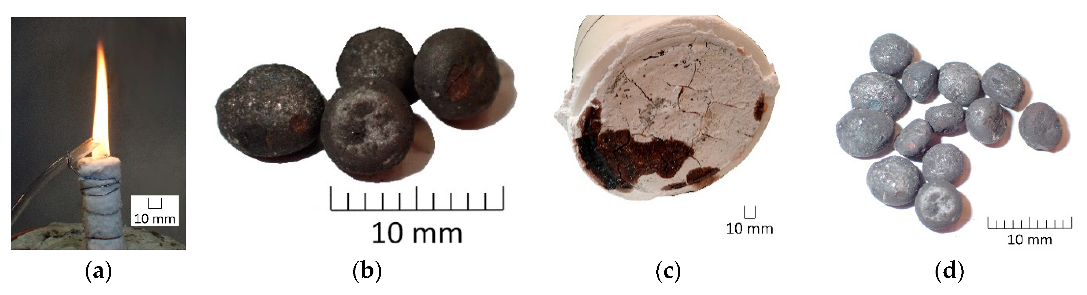
The novel pyrometallurgical recycling process presented in this paper is characterized by the recovery of an alloy with a simultaneous utilization of lithium and phosphorus via the gas flow. The following points provide a more detailed insight into the theoretical considerations and practical implementations for the most efficient recovery of valuable metals from LIBs using this process. Initially, appropriate analyses were carried out to better understand the behavior of cathode materials in high-temperature applications under reducing conditions. To determine the lithium removal rate without the presence of phosphorus, the cathode material lithium cobalt oxide (LCO) was examined in an experiment. In addition to the successive optimization of the reactor concept and adaptation to the waste stream from spent LIBs, another experiment with LCO in a modified setup was performed and compared to the previous one. To verify the basic suitability of the pyrometallurgical apparatus for the simultaneous removal of phosphorus and lithium via the gas flow, experiments were carried out with the cathode material lithium iron phosphate (LFP).

2. Process Concept and Methods

2.1. Used Materials

In total, three different experiments were carried out with two types of feedstock. As Windisch-Kern et al. [34] have already described, experiments with black mass from a pre-processing step have already shown that lithium could be removed to a considerable extent. As this has raised additional questions, a detailed investigation of the pure cathode materials, i.e., LCO, lithium nickel manganese cobalt oxide (NMC—chem., LiNi0.33Mn0.33Co0.33O2), lithium nickel cobalt aluminum oxide (NCA—chem., LiNi0.8Co0.15Al0.05O2) and LFP, was indispensable. For the purpose of clarifying the questions dealt with in this paper, the materials LCO and LFP were used, which were produced by the Chinese company Gelon Energy Corporation. The appearance of this feedstock can be described as a fine, black powder. Since this carbo-thermal process requires a reducing agent and the graphite bed in the reactor is only used for energy input, graphite powder from coke pellets of a steel mill is added. The graphite cubes with a side length of 2.5 cm come from electrodes of a steel mill and have an average purity of 99% with an electrical resistance of 4–8 µΩm and a density of 1.55–1.75 gcm−3. [35] The amount of graphite powder required for the reduction was determined by stoichiometry of the respective cathode material. For this purpose, the weighed mass of the cathode material was multiplied by the molar ratio of LiCoO2 or LiFePO4. After determining the moles O by multiplying the mass O by the relative atomic mass of O, the necessary mass of C was calculated by using the relative mass of C and assuming that a conversion to CO takes place in the reactor. The corresponding percentage C requirement is finally obtained by a rule of three of the masses of O and C. Table 1 shows the composition of the input materials determined from their stoichiometric composition.
The products obtained from the experiments were examined by ICP-OES and ICP-MS by means of aqua regia digestion according to ÖNORM EN 13657:2002-12.

2.2. Material Specific Investigations

Since the behavior of the individual cathode materials at high temperature applications is hardly or not at all described in the literature, detailed investigations were undertaken at the Chair of Thermal Processing Technology. These included analyses in a Hesse Instruments EM 201 with an HR18-1750/30 furnace heating microscope. The results should be used for planning the process control in the following experiments in the inductively heated reactor, which is presented in Section 2.3. Furthermore, a better understanding of the behavior of the cathode materials should be gained. To be able to simulate the planned process as detailed as possible, graphite powder was added to the cathode material. The addition of graphite powder was carried out to an extent of 10 wt.% under the assumption that C is converted to CO2 and transported away via the argon-purged atmosphere. The mixture of the corresponding cathode material and graphite powder was examined with at least one reproduction experiment. For better comparability a uniform heating rate was always set, which corresponds to the maximum possible with the heating microscope used. This is primarily to ensure the shortest possible residence time in the furnace chamber since interactions of LCO with the furnace material consisting of Al2O3 have been determined and damage to this should be prevented as far as possible. Up to a temperature of 1350 °C, a heating rate of 80 °C/min was selected, from 1350 to 1450 °C 50 °C/min and up to 1700 °C a heating rate of 10 °C/min with a holding time of 15 min at 1700 °C was dialed. To avoid oxidation with the ambient air, the reactor was flushed with argon at a flow rate of 2 L/min. A maximum furnace temperature of 1700 °C was chosen, which allows for an approximate sample temperature of 1630 °C.
Figure 1 illustrates the standardized sample preparation. The material is centrally positioned in a cylinder with a diameter of 3.5 mm and a height of 2.5 mm on an Al2O3 platelet with an approximate weight of 0.1 g.

2.3. Reactor Concept

The novel reactor concept, which was constructed at the Chair of Thermal Processing Technology of the Montanuniversitaet Leoben, is based on the inductive heating of graphite pieces in a packed bed reactor. The cornerstone of knowledge generation in this field was laid at the chair already in 2012, by the EU subsidized project RecoPhos for the pyrometallurgical treatment of sewage sludge ash for simultaneous recovery of phosphorus and the contained valuable metals. Its results are described by Schönberg et al. [36] and Samiei et al. [37]. Based on this and corresponding follow-up projects, also in the field of basic oxygen furnace slag (BOFS) treatment, a batch operated post-lab-scale plant and a pilot-scale plant as a continuous process have been developed and built. This knowledge advantage was used to adapt the mechanism for pyrometallurgical recovery of valuable metals from processed LIB material in two ways. On the one hand, the theoretical idea of the continuous reactor, which should be conceptually similar to the set-up from research work in the field of sewage sludge ash and BOFS utilization, is applied. On the other hand, the post-lab-scale setup developed in the subject area mentioned above can initially be used for first experiments without further adaptations. In the long term, the realization of larger scales and corresponding throughput of recycled material as a continuous unit is planned. Intensive research activities on a small scale are indispensable for the most efficient implementation of gradual scale-ups to industrial maturity. In view of the process development as well as the knowledge gained about the input material, the previously mentioned apparatus in batch operation, the so-called InduMelt plant, is used for this purpose. These two process concepts and their respective challenges and developments are explained in detail below.

2.3.1. Continuous Reactor Concept

In order to treat the expected future waste stream from used LIBs, a technology with correspondingly high throughput rates is required. The currently pursued approach at the Chair of Thermal Processing Technology is based on a continuous reactor concept which currently exists as a pilot plant with a material throughput rate of 10 kg/h. Even if, according to initial findings from investigations of the LIB black matter, the design must differ from that used for sewage sludge ash and BOFS, the basic principle remains the same. Ponak [38] describes the so-called InduRed reactor as an cylindrical arrangement of refractory materials filled with pieces of electrode graphite which allow a horizontal and radial homogeneous temperature distribution when heated by the induction coils, as seen in Figure 2.
The process starts with the material feed from a feed vessel above the reactor via a screw conveyor and a low volume of argon. Inert gas purging is highly relevant at this position, especially at higher temperatures, as the graphite bed is protected against oxidation by possible false air and, mainly, to direct small ash or black matter particles directly onto the graphite surface. In the first zone, the melting zone, the fine-grained material inserted is heated to melting temperature without reaching the reduction temperature of the critical component phosphorus. The resulting molten film then moves through the reactor to the reduction zone. In this zone the corresponding energy is induced so that the reduction temperature is reached close to the implemented gas flue. At this point, it has to be mentioned that the graphite pieces are not supposed to participate in the reduction reactions and serve only as a susceptor material. Added carbon powder functions as a reductant. Through this reaction process, phosphorus is converted into the gaseous phase and can be removed directly from the reactor via the gas flue by means of a negative pressure-generating induced draft fan. Downstream there is a post-combustion chamber in which external air or oxygen are used to convert elemental phosphorus to P2O5. The subsequent hydrolysis finally enables the production of phosphoric acid. The remaining material in the reactor moves on to the discharge zone, where the third and last coil provides enough energy that the phosphorus-free material does not reach the solidification temperature and finally leaves the reactor via the reactor floor. The resulting material can be divided into a metal and a slag fraction, which, however, are not yet separated from each other in the current expansion stage and are collected in a vessel below the reactor output.
The advantages of this apparatus are manifold. In comparison with an electric arc furnace (EAF), no molten bath of metal is formed so that the P2 (g)–Fe (l) contact possibility and in further consequence the formation of iron phosphide can be decreased immensely. This fact is promoted by a thin molten film, which massively shortens the distance of mass transport. In this case it is particularly important for the diffusion of P and its removal as gas. The graphite pieces offer a large surface area for reactions and by coupling into the induction field, the heat for the endothermic reduction reactions is permanently provided directly at the respective particle surface. Even if the energy demand is increased, the main form of the reduction reaction is direct reduction, resulting in a lower carbon demand. [38] In the course of the reaction processes in the reactor, a very low oxygen partial pressure and a correspondingly high CO to CO2 ratio is established, which in turn promotes the reduction reactions [40].
In order to use this process also for the waste stream from spent LIBs, the reactor design and the corresponding post-treatment of the output streams must be adapted. The input material for the planned continuous process comes from a pre-treatment plant, which is a fine fraction as low in Cu and Al as possible consisting of a mixture of cathode and anode materials. After being fed into the pyrometallurgical reactor, the material should react according to the principle described above. The most important difference is that the idea of the treatment of this material is to remove not only phosphorus but also lithium from the reactor via the gas flow. An initial concept for the post‑treatment of the liquid fraction, which leaves the reactor chamber via its bottom, provides for an oxygen inlet. Thus, in accordance with the different oxygen affinities, for example, the input stream of NMC, LCO, NCA and LFP should result in the purest possible CoNiFe alloy. Oxygen-affine elements such as Mn and Al, as well as the residues of P and Li that are not removed via the gas phase, are to be slagged. The resulting products can therefore either be sold on the market as raw materials as required, or further broken down into their constituent parts in further post-treatment steps, for example via the hydrometallurgical route. A further additional important step to be investigated is the post-treatment of the resulting gas fraction. In particular, it will be necessary to implement a corresponding process for the separation of Li and P and consequently to treat them further according to the resulting qualities. As the points just described show, a combination with other processes should be aimed for. With regard to the overall reactor design, an adaptation of the current development will be essential. This includes issues such as the optimal refractory material for the reactor wall or a possible need to expand the gas extraction system.

2.3.2. Batch Reactor Concept

Based on the technology described in Section 2.3.1, the process design shall be adapted to the requirements of the black matter out of LIBs. For this purpose, in-depth tests were carried out for a better understanding of the material to be processed, which are partly described in Windisch-Kern et al. [34]. Since the scale of a continuous pilot plant for experiments of this kind would firstly be too complex and secondly would not correspond to the research status at the Chair of Thermal Processing Technology in the LIB field, the experiments were carried out on a post-laboratory scale. For this purpose, the reactor concept of the unit operating in batch mode was adopted from the developments in the field of sewage sludge ash and BOFS, as shown in Figure 3a and hereinafter referred to as Design 1. The system behind it is similar to the continuous concept, with the difference that the material to be investigated is already in the reactor at the beginning of the experiment and there is no material output via the ground. Most of the material melted during the experiment is accumulated and collected at the bottom of the reactor or adheres to the cube surface as spherical formations. In addition, the gas outlet is also not subjected to negative pressure, so that the resulting gases leave the reactor without constraint. For the construction of the reactor, an Al2O3 ring with a diameter of 20 cm, Al2O3 mortar and refractory concrete were used. The graphite bed provides a cube surface of 1725 cm2 for the transfer of the induced heat. An insulation around the reactor has the function of the protection of the induction coil, to reduce the heat losses and to enable as good a separation as possible from ambient air.
To enable a qualitative measurement of the exhaust gas flow, a gas scrubber was additionally installed at the outlet of the gas flue (Figure 3b). This was realized with a bubbling frit in which the exhaust gas is enriched in a 2.5 molar H2SO4 solution. The temperature was measured on the outside of the reactor by two category S-thermocouples and inside the reactor by two category K-thermocouples. Due to the expected breakage of the second mentioned thermocouples, they are only used to find a correlation between the outside temperature and the inside temperature.
Preliminary tests have shown that LCO, with its high cobalt content, is highly reactive to the crucible material of Al2O3. In addition, sampling proved to be particularly difficult because it was not possible to separate the black mass clearly from the mortar. This makes it almost impossible to close the mass balance in the future. Another disadvantageous fact of this reactor concept is that, due to its position, the highest induction of the current takes place in the upper part of the reactor. Because of the inevitable turbulence in the reactor during the experiment due to the gases, the material accumulates at the bottom of the reactor, so the energy supply position is suboptimal. To take into account the mentioned disadvantages, a new design was developed, which is shown in Figure 4 and hereinafter referred to as Design 2.
This is a cylindrical crucible with a half-arc bottom made of MgO. It was placed centrally on a refractory concrete structure in a way that only the lower part of the MgO crucible is within the induction coil. Appropriate insulation made of refractory matting should reduce the heat loss and thus the energy requirement and protect as far as possible against the ingress of false air from the environment. To be able to make a qualitative statement about the escaping gas during the test, an exhaust pipe made of Al2O3 was again implemented. The temperature was measured by a category S-thermocouple from below and in the reactor by two category K-thermocouples.
For a direct comparison of the different reactor concepts of the InduMelt plant, the same feedstock, the mixture LCO‑C mentioned in Section 2.1 with a quantity of 550 g, was examined in both crucible concepts. To ensure that reproducible initial conditions prevailed in both designs, the charging of the cubes and the sample was also performed uniformly in all experiments. Thus, at the beginning, 15 cubes were positioned in the reactor and one third of the sample was charged onto them. After positioning a K-thermocouple, another 10 cubes were performed followed by addition of another third of the sample. This was repeated a second time to finally fill the reactor with 11 cubes after positioning the second K-thermocouple. This filling quantity also represents the maximum possible capacity of Design 1. The content of Design 2 is approximately 25% larger which, however, was not utilized due to the aforementioned comparability with Design 1. After the experiment, all components of the reactor are weighed. The adhesions to the graphite cubes are removed by light mechanical processing. These adhesions are consequently separated into fractions larger and smaller than 1 mm by means of a sieve tower, together with the remaining finer fraction that may be produced. With the aid of a magnet, these are further separated into magnetic and non-magnetic, with the former finally being assigned to metal and the latter referred to as slag. Larger pieces of metal are collected together after checking with a magnet. The same is done with larger non-magnetic pieces, which are again referred to as slag. The individual fractions are finally weighed and analyzed. The main difference in sampling between Design 1 and Design 2 is the collection of the diffused areas of the grout or reactor adhesions, which will be discussed in more detail in Section 3.2.1.
The aim is to determine the interaction between the cathode material respectively the reaction products of which and the corresponding crucible material and to compare them with each other. On the other hand, the individual transfer coefficients should provide information on whether the choice of the crucible material affects the recovery rates of the individual species.
In a third trial, the basic suitability of the overall reactor concept for the treatment of LFP with the aim of removing Li and P from the material was investigated. For this purpose, Design 1 from Figure 3a was selected again in which a quantity of 394.5 g of the mixture LFP‑C from Section 2.1 was charged into the reactor.

3. Results and Discussion

3.1. High-Temperature Properties of the Cathode Materials Used

In a first step to determine the behavior of cathode materials from LIBs at temperatures above 1600 °C and under reducing conditions, experiments were performed in a heating microscope. Figure 5a provides a picture of the result of the experiment with the mixture with LCO. A strong dark blue coloration was observed on the platelet. This may be due to a reaction between the Al2O3 platelet and cobalt to form cobalt aluminate with its typical blue appearance. [41] The product of the melting process under reducing conditions is a metal structure, which can be classified as strongly magnetic after examination with a magnet. This magnetism could also be detected in experiments with LFP, which is shown in (b). In contrast to the experiment described above, there is no blue coloration, but a brown to reddish appearance.
Figure 6 displays the recording of the replication experiment LCO‑C via optical measurement in the heating microscope. In Figure 6 the cross-sectional area of the experiments with LCO‑C (black dotted line) and its repetition LCO‑C‑Re (green dotted line) over temperature during the experiment is shown. This cross-sectional area is the size of the sample cylinder detected by the heating microscope respectively its change with temperature increase.
It should be mentioned that by comparing the recorded images with the corresponding values of the cross-sectional area, faulty measurements caused by incorrect detection of the baseline by the heating microscope were removed from the data series. Since the basic behavior at the individual temperatures is nearly identical and differs only by different cross-sectional areas, a mean value was determined, which represents the red line. When looking at Figure 6, the first noteworthy surface changes can be observed from 675 °C onwards. From 675 °C to 845 °C a growth of the cross-sectional area was detected, which subsequently decreased again to 1054 °C with single deflections to about 80% of the original area. Up to a temperature of 1127 °C an increase in magnification was detected, which remained relatively constant with single deflections up to 1380 °C. From this temperature on, the cross-sectional area decreased continuously with a smaller slope in the range of 1393 °C to 1507 °C and a significant decrease up to 1525 °C. Up to the end there was a further decrease of the cross-sectional area, which, however, when looking at the single images from the heating microscope, can be traced back to the continuous distribution of the molten material on the platelet.
Figure 7 illustrates the results of the experiments in the heating microscope with the mixture LFP‑C. The previously mentioned measurement error was particularly striking in the first experiment of LFP‑C (black dotted line in Figure 7) in the range from 1163 °C to about 1400 °C. Nevertheless, a corresponding trend could be determined by correctly measuring individual values in some cases, which in turn could be confirmed by a repeated measurement of LFP‑C‑Re (green dotted line in Figure 7). Again, the mean value is shown in the red curve.
The results show that up to a temperature of approximately 920 °C the cross-sectional area first rises slightly and then falls back to just below 100% of the initial value. Afterwards, a pulsating enlargement of the surface takes place which decreases at about 1200 °C. After a further pulsating behavior between 1240 and 1310 °C the area is continuous again to remain relatively constant from about 1410 °C on.

3.2. InduMelt Experiments: Process Development and Suitability of the Different Reactor Concepts

The main part of the experimental investigation of LIB cathode materials was examined in the InduMelt plant. For this purpose, three experiments were carried out, which will be considered separately below according to their purpose. According to the results of the analyses, as described in Section 3.1, the maximum necessary process temperatures for the tests in the InduMelt plant were set at 1525 °C for LCO‑C and 1400 °C for LFP‑C. This is due to the fact that the sample material should be completely liquid at this point in time according to the heating microscope.

3.2.1. Results from Experiments with LCO‑C in Both Reactor Designs

The first experiment, which is described in detail below, was carried out in Design 1. The entire experiment lasted nearly 8 h. Figure 8a shows the power input of the induction unit and the corresponding temperatures over the test time. Two type S‑thermocouples (S-TC 1 and S-TC 2 in Figure 8a) were used on the reactor surface and two type K‑thermocouples inside the reactor. The latter were initially installed at different heights in the reactor, one in the area of the first cube layer (K-TC bottom) and one in the upper area (K-TC top). In contrast to the S‑thermocouples, the measurement results of the K‑thermocouples are subject to considerable fluctuations due to melting of their insulation, influences of the material in the reactor, etc. However, an approximate temperature spread of the different thermocouple types of 500 °C could be determined up to the end.
During the process, noticeable anomalies were documented. Starting at 0.95 h and a K-TC bottom temperature of 450 °C a strong formation of condensate in the exhaust pipe to the gas scrubber was observed. This was attributed to the drying of the mortar. The temperature spread of the S‑thermocouples at 1.75 h (124 °C S-TC 1) can be explained by a slight realignment of S-TC 1. Especially interesting was the continuously increasing white smoke from the exhaust pipe, which started at 5.10 h and 1180 °C internal temperature and stopped at 1341 °C. This resulted in a continuous white deposit in the exhaust pipe of the scrubber, as shown in Figure 8b. After the white smoke formation stopped, the acid in the scrubber gradually changed from transparent to a slightly yellow liquid. The assumption that the white deposits are Li or a corresponding compound could be confirmed after analysis of the liquid in the scrubber, which are summarized in Table 2.
Sampling after the experiment revealed a total of 4 fractions, the results of which are shown in Table 3.
The fraction defined therein as slag could be identified as dark to light grey non-magnetic pieces smaller than 10 mm with minimal metallic inclusions, as illustrated in Figure 9a. The mortar shown represents the part into which the test material has diffused. This is optically visible by a dark discoloration of the originally white mortar. In Figure 9b the reactor is demonstrated from below after the concrete floor has been separated. During sampling, care was taken to find the clearest possible separation between the white mortar and the diffused areas, but this proved to be very difficult. The largest product of the experiment in terms of mass was the metal fraction, which could be obtained in pieces larger than 10 mm. The metal piece shown in Figure 9c serves as an example. The analysis showed an impressive purity of 100% Co and an impurity of only 0.01% Li. It should be noted that there may be some variation in sampling and digestion errors, resulting in the overall result not reaching exactly 100%. The fourth fraction was a powder with particles smaller than 1 mm, as can be seen in Figure 9d, which was mostly magnetic. This property is also confirmed by analyses with a cobalt content of 53.4%.
Taking into account the respective weighed masses and the analysis results, the transfer coefficients of the individual elements of the fractions were calculated. In detail, the analyses from ICP-MS and ICP-OES of the individual fractions were converted to mass percent and multiplied by the weighed mass at sampling. By adding the respective element masses, a total mass per element could be determined. This represents the amount that was still detectable in the fractions in the reactor after the test. Afterwards, a comparison of the masses before and after the experiment was carried out. The difference was assumed to be a transfer into the gas flow leaving the reactor during the experiment or a transfer into the individual solid fractions. The results of this calculation can be seen in Figure 10.
At this point it should be mentioned that the transfer coefficients determined must be seen as initial guide values and internal comparison values and must be confirmed accordingly by repeated experiments in the optimum reactor setup. Nevertheless, the trend was also observed in experiments with NMC and NCA, as described in Windisch-Kern et al. [34]. The result of the transfer coefficients in Figure 10 shows a Li removal rate of over 76% into the gas stream from the cathode material used. Based on the thermokinetic consideration of LCO by Kwon et al. [16] and assuming that most of the Li has left the reactor during the phase of white smoke (approximately 1160–1340 °C), it can be assumed that it is Li2O. The transfer of over 21% Li into the mortar can be considered as an undesirable result. The percentage of Li in the slag is not negligible in the analyses (Table 2) with 5.6%, but due to the small quantity of slag it is insignificant for the total consideration with 0.6%. The small amount of Li in the metal (0.1%) is a great result with regard to the purest possible metal fraction. A further potential for improvement can be seen when considering the Li content of 1.8% in the powder, whereby this value can possibly be lowered with a longer holding time of the final temperature. The result of Co can be interpreted as extremely promising. Only 7.5% is found in the powder and 95.2% in the metal, which can be directly transferred for further use in the corresponding metal industry. The resulting difference to 100% can be explained by the extremely difficult sampling, especially the identification of the individual fractions and the subsequent weighing. At this point, the proportion in the slag and mortar can also be neglected with less than 0.1%. The comparison of these results with other processes is difficult at this point because the composition of the input material differs significantly from a real waste stream of LIB. Nevertheless, by using pure cathode material, without impurities such as Al or Cu, a value of the theoretically maximum possible removal rate of Li can be determined. Vest [15] describes a Li2O transfer rate from the waste stream of LIB of 40.5% in their process based on an electric arc furnace. Even though a direct comparison with this value is not possible, the gap between Vest’s result and the theoretically possible value in this method shows an enormous potential.
Much more remarkable in this context is the result of Design 2. The temperature record of the LCO‑C experiment in Design 2, which can be viewed in Figure 11 in combination with the power input over time with the same naming as in the previous experiment described above, shows that the temperature is highest in the lower part of the reactor. Thus, the goal of the reactor design of a more targeted temperature provision in the lower area could be realized.
The extreme fluctuations of the K‑thermocouples between the test duration of approximately 1 to 3 h could be explained in retrospect in such a way that after the insulation around the thermocouple wires had melted, they reconnected at a higher point in the reactor. The initial theory could be confirmed when the reactor was opened after the experiment, because the thermocouples could be found in the upper part of the reactor free of cubes and no longer in the cube bed. Again, a white smoke formation with the same deposits in the exhaust pipe of the gas scrubber could be detected. This phenomenon occurred at an S-thermocouple temperature range from 1165 to 1340 °C. Again, as the smoke intensity decreased, a successive discoloration of the acid in the scrubber from transparent to a light yellow was to be determined. The results of the acid analysis from the gas scrubber can be taken from Table 4. The high value of Li confirms the impression, as already assumed in the experiment in Design 1, that Li can be removed from the reactor via the gas flow.
The results of the investigation of the test material LCO‑C in Design 2 can be seen in Table 5. Essentially, the analysis differs from the experiment in Design 1 only in that there was no mortar due to the construction. When the MgO crucible was weighed after the experiment, it was found to be 81.2 g heavier than the initial weight. This could be attributed to adhesions on the crucible, which were mechanically extracted as completely as possible. The result was a fine powder. Despite considerable mechanical effort, only 3.8 g could be removed from the crucible without damage, which will be referred to as crucible adhesion in the following.
The fractions did not differ in their appearance from those in Figure 9a,c,d. Only the metal pieces were larger, as shown in Figure 12. Analysis of the metal fraction revealed a purity of Co of 93.9% with a negligible amount of 0.12% Li.
The transfer coefficients, which are illustrated in Figure 13, were determined from the results in Table 5, taking into account the corresponding weight changes of the individual fractions during the experiment.
This result represents a unique selling point in the pyrometallurgical processing of cathode material from LIB. Compared to Design 1, even though only 85.9% of the Co was transferred to an almost pure Co-metal phase, more than 97% of the Li were removed from the material and the reactor via the gas flow. Thus, a nearly 21% higher Li removal rate could be achieved in Design 2.
Since the attribution of the Co not found to the gas phase is rather questionable to this extent and cannot be traced back exclusively to errors in sampling and analysis, a closer look at the results is necessary. In addition to the result display in Figure 13, another variant is possible. It is assumed that the difference of the weighed crucible adhesion (81.2 g) to the extracted amount (3.8 g) consists of the same composition as the extracted fraction. This results in a lithium removal rate of 81.7% with a Co value that was not found (i.e., attributed to the gas phase) of −3.12%. This variant cannot clarify the difference to 100%, but by combining the two methods, one obtains a range in which the transfer coefficients move.
Besides this result, Design 2 also turns out to be a better choice when considering the interactions between the sample material and the reactor. As shown in Figure 14a, a massive attack of the reactor wall was observed in Design 1 (Al2O3) with ring diameter reductions of up to 0.2 mm. On the other hand, Figure 14b shows the reactor in Design 2 (MgO) after the experiment. From the difference between the weighing before and after the test, it is known that the reactor was over 81 g heavier afterwards. The theory of adhesion to the reactor can also be seen in the illustration, whose boundary is marked with the red arrow.
This factor is particularly important for long-term experiments in a continuous set-up. If the sample material and the Al2O3-ceramics are in contact for a longer period of time, this attack would lead to a destruction of the reactor. In addition to the advantages already mentioned, Design 2 also features a much simpler construction and therefore easier sampling. A drawback of Design 2 is the higher energy input required, which can be seen in the comparison of the power curve of Figure 8 and Figure 11. However, this can be solved by an improved positioning of the induction coil. Furthermore, the consequences of adhesions in continuous operation must be investigated.
Even though the target temperatures were not reached in the experiments with LCO‑C, it can still be assumed that a sufficiently high temperature was reached. Firstly, the temperature in the reactor was measured in the space between the refractory mat and the graphite cubes, as mentioned above, which implies that the temperature in the cube bed must have been even higher due to the heat input in it. In addition, if the temperature was too low, the appearance of the products would be different. An example of this is the metal from Co, as shown in Figure 9c and Figure 12, whose melting point is known to be 1495 °C.

3.2.2. Results from Experiments with LFP‑C

The test with LFP‑C was carried out in Design 1. Since the temperature measurement via the K‑thermocouples was already faulty from the beginning of the experiment and a repair was no longer possible at this point in time, only the curves of the recordings from the S‑thermocouples are visible in Figure 15. However, the delta value to the K‑thermocouples should be similar to that in the LCO‑C experiment in Design 1, whereby approximately 500 °C can be added to the value of the S-thermocouples to determine the internal temperature at higher temperatures.
During the heating process, smoke development was particularly noticeable at an outside temperature of approximately 750 °C (approximate internal temperature of 1210 °C), which completely ignited after a short time. This flame, which is an indication of the reaction of phosphorus with oxygen [42], could finally be detected constantly up to an outside temperature of approximately 860 °C (approximate internal temperature of 1310 °C) as shown in Figure 16a. During this time the acid in the gas scrubber changed its color to a brownish liquid. The results of the exhaust gas analysis can be taken from Table 6.
In the exhaust gas analysis only a small value for P and a very small amount of Li could be found, which is possibly due to the formation of a flame out of the exhaust pipe. In order to be able to make a statement about the efficiency of the reactor concept for the recycling of LFP, the results of the ICP-OES or ICP-MS must be examined more closely.
A total of 5 fractions could be detected during sampling. The appearance of the fraction classified as non-magnetic slag (Slag 1) differed significantly from that in Figure 9a. Individual spheres with a diameter of up to 5 mm were detected, as shown in Figure 16b. In comparison with the appearance of the magnetic metal fraction in Figure 16d, the difficulty of clearly classifying the individual fractions is obvious. The analysis showed that the Fe content in the slag was even higher than in the material identified as metal. In addition, however, a significant amount of Li (3.19%) and P (15.9%) was also analyzed. Slag 2 in Table 7 is a non-magnetic powder with particles smaller than 1 mm the appearance of which is the same as in Figure 9d. The same applies to the magnetic material identified as powder. In this experiment, care was again taken during sampling to separate as much diffused areas of the sample material from the mortar. These brownish areas are also visible in Figure 16c, which shows the ceramic ring with the mortar after removal of the refractory concrete. Analysis of the metal displayed in Figure 16d shows only 51 wt.% Fe and over 8 wt.% P. This low Fe content suggests that no complete reduction has occurred. A further indication for the correctness of this assumption is the fact that during mechanical processing of the fraction with a hammer, the spheres disintegrated into a powder already with a small amount of force.
Referring to the respective masses of the individual fractions, the transfer coefficients can be taken from Figure 17.
Of particular interest are the removal rates of Li (68.4%) and P (64.5%) over the gas flow. The remaining amount of Li here is distributed relatively evenly among the other fractions with a slight concentration on the remaining powder. As already mentioned, it is reasonable to assume that no complete reduction of Fe has occurred. This is also reflected in a considerable value of phosphorus in the metal fraction.
A direct comparison of the experiments in Design 1 shows that the Li removal rate for LFP‑C of 68.4% is 8% lower than in the experiment with LCO‑C. However, the parallel removal of phosphorus of 64.5% represents a respectable result. It also can be seen that in both the LCO‑C test with a transfer coefficient of 21.1% (Figure 10) for Li and the LFP‑C test with 6.1% (Figure 17), a significant amount of Li was transferred to the mortar. If the results of LCO‑C in Design 2 are also included, it can be assumed that gasification rates for LFP‑C are better in this construction method. Looking at the transfer coefficients in Figure 17, a significant portion of the Fe (11.5%) is attributed to the gas flow. De facto, this is the amount that was not recovered during sampling compared to the input amount. The correctness or falsification of this classification and the above mentioned assumptions must be investigated in further experiments. Particular attention must be paid to safety in the pyrometallurgical removal of phosphorus from LIB, consisting of the cathode material LFP, in the exhaust gas post-processing. In addition to oxidation in the air, as shown in Figure 16a, the high toxicity [43] is also of particular importance. These factors must be given special consideration in future developments of the reactor concept presented.

4. Conclusions

Within the scope of this paper, the suitability of a new pyrometallurgical recycling process associated with materials from LIBs for the recovery of valuable metals was investigated. With the background of a continuous adaptation of the reactor concept to the waste stream from spent LIBs, two different reactor designs were used, in each of which the cathode material LCO with carbon addition was examined for better comparability. In a third trial, the basic capability of the technology for the treatment of LFP was also examined. In addition, knowledge about the behavior of the examined cathode materials used in high-temperature applications was investigated in an upstream step in a heating microscope.
The transfer coefficients determined in the experiments of the novel pyrometallurgical recycling process serve exclusively as a comparison of the efficiency of the presented reactor concepts or as a first benchmark of the basic suitability of the process for the treatment of LFP.
From the experiments in the heating microscope the maximum necessary temperatures for the transformation into a molten phase could be determined. This state of aggregation is necessary in the long run to meet the requirements of the theoretically determined principle of a continuous process. For the experiments with LCO a temperature of 1525 °C and for LFP 1400 °C could be determined.
In the trial LCO‑C in Design 1, 95.2% Co of the original input fraction was converted into the metal, with a purity of Co of 100%. Due to the high Li content in the mortar, only 76.4% of the Li could be transferred into the exhaust gas flow. This contrasts with the result of the experiment with LCO‑C in Design 2. Its analysis shows a metal purity of 93.9% Co and a remarkable lithium removal rate in a range from 81.7% to 97.3%. In addition to this impressive lithium removal rate, Design 2 has also proven to be the better choice for future use due to its interaction with the feed material. For example, massive interactions and attacks on the Al2O3 crucible have been detected in Design 1, whereas there were no physical damages with the MgO crucible in Design 2. Although the danger of destruction of the reactor wall during long-term experiments in a future continuous process has been averted, the effect of the detected adhesions on the MgO crucible still needs to be investigated in further tests. However, the initially formulated goal of a more targeted heat supply in the lower part of the crucible was achieved by Design 2.
The experiment with LFP‑C was performed in Design 1 and achieved a lithium removal rate of 68.4% with parallel phosphorus removal of 64.5%. Since the results of the LCO‑C experiments showed that a higher lithium removal could be achieved when using Design 2, a repetition of the LFP‑C experiment in this setup can be expected to result in a higher removal rate. In addition, since sampling in this experiment has proven to be particularly difficult due to the appearance of the fractions, and since detailed examination of the results has revealed questions that need to be clarified, such as the undetectable amount of Fe, further investigations are indispensable.
Nevertheless, it can be summarized that Design 2 with its MgO crucible has proven to be a better choice with regard to its suitability for pyrometallurgical treatment of material from LIBs. This is due to its inertness to the sample material as well as the higher Li removal rate determined. In addition, it was found that the use of the technology is also suitable for the cathode material LFP and that considerable P and Li removal rates have already been achieved. However, in order to be able to treat the fluctuating waste stream from spent LIBs with an appropriate efficiency, in-depth investigations are needed beforehand to gain knowledge of the behavior of all common cathode materials. In order to increase efficiency, the fraction referred to as slag must also be subjected to more detailed investigations in the future, for example with an XRD analysis. From this, knowledge of the phases present is to be generated and the formation of these is to be suppressed with targeted measures. In the current development phase, this has not yet been the focus of research. Furthermore, it is necessary to identify the influence of additional fractions such as Cu and Al from conductor foils on the process.
Compared to commercial techniques used today for recycling spent LIBs, the simultaneous recovery of lithium and phosphorus via the process presented in this paper is its most significant advantage. This first potential assessment for pyrometallurgical recovery of Li would also theoretically meet the requirements of the proposed amendment to the EU Directive 2006/66/EC of a Li recovery up to 70% by 2030. Aspects such as the economics, energy efficiency and environmental impact of this intermediate step in the overall recycling chain, as well as possible recovery rates of a waste stream of spent LIBs in the new reactor design, need to be determined in further studies.

Author Contributions

Conceptualization, A.H. and S.W.-K.; methodology, A.H.; investigation, A.H., S.W.-K. and C.P.; resources, A.H., S.W.-K. and C.P.; writing—original draft preparation, A.H.; writing—review and editing, A.H., S.W.-K., C.P. and H.R.; visualization, A.H.; supervision, C.P. and H.R.; project administration, C.P.; funding acquisition, H.R. All authors have read and agreed to the published version of the manuscript.

Funding

This research was funded by the Zukunftsfonds Steiermark with funds from the province of Styria, Austria, grant number GZ: ABT08-189002/2020 PN:1305.

Institutional Review Board Statement

Not applicable.

Informed Consent Statement

Not applicable.

Data Availability Statement

The data presented in this study are available on request from the corresponding author.

Conflicts of Interest

The authors declare no conflict of interest.

References

  1. Pillot, C. The Rechargeable Battery Market and Main Trends 2018–2030. In Proceedings of the ICBR 2019, Lyon, France, 18–20 September 2019. [Google Scholar]
  2. Palacín, M.R.; de Guibert, A. Why do batteries fail? Science 2016, 351, 1253292. [Google Scholar] [CrossRef] [Green Version]
  3. Zhang, X.; Xie, Y.; Lin, X.; Li, H.; Cao, H. An overview on the processes and technologies for recycling cathodic active materials from spent lithium-ion batteries. J. Mater. Cycles Waste Manag. 2013, 15, 420–430. [Google Scholar] [CrossRef]
  4. Ordoñez, J.; Gago, E.J.; Girard, A. Processes and technologies for the recycling and recovery of spent lithium-ion batteries. Renew. Sustain. Energy Rev. 2016, 60, 195–205. [Google Scholar] [CrossRef]
  5. Sojka, R.; Pan, Q.; Billman, L. Comparative Study of Lithium-Ion Battery Recycling Processes. In Proceedings of the ICBR 2020, Salzburg, Austria, 16–18 September 2020. [Google Scholar]
  6. Li, L.; Zhang, X.; Li, M.; Chen, R.; Wu, F.; Amine, K.; Lu, J. The Recycling of Spent Lithium-Ion Batteries: A Review of Current Processes and Technologies. Electrochem. Energy Rev. 2018, 1, 461–482. [Google Scholar] [CrossRef]
  7. Blengini, G.A.; Latunussa, C.E.; Eynard, U.; Torres de Matos, C.; Wittmer, D.; Georgitzikis, K.; Pavel, C.; Carrara, S.; Mancini, L.; Unguru, M.; et al. Study on the EU’s list of Critical Raw Materials (2020) Final Report; Publications Office of the European Union: Luxembourg, 2020. [Google Scholar] [CrossRef]
  8. Arthur D Little. Available online: https://www.adlittle.com/en/insights/viewpoints/future-batteries (accessed on 26 December 2020).
  9. Huang, B.; Pan, Z.; Su, X.; An, L. Recycling of lithium-ion batteries: Recent advances and perspectives. J. Power Sources 2018, 399, 274–286. [Google Scholar] [CrossRef]
  10. Duesenfeld GmbH, Ecofriendly Recycling of Lithium-Ion Batteries. Available online: https://www.duesenfeld.com/recycling_en.html (accessed on 26 December 2020).
  11. Accurec Recycling GmbH, Lithium Batterie Recycling. Available online: https://accurec.de/lithium?lang=de (accessed on 26 December 2020).
  12. Redux GmbH, Redux Smart Battery Recycling. Available online: https://www.redux-recycling.com/de (accessed on 26 December 2020).
  13. Arnberger, A.; Coskun, E.; Rutrecht, B. Recycling von Lithium-Ionen-Batterien. In Recycling und Rohstoffe; Thiel, S., Thomé-Kozmiensky, E., Goldmann, D., Eds.; TK Verlag: Nietwerder, Germany, 2018. [Google Scholar]
  14. Liu, C.; Lin, J.; Cao, H.; Zhang, Y.; Sun, Z. Recycling of spent lithium-ion batteries in view of lithium recovery: A critical review. J. Clean. Prod. 2019, 228, 801–813. [Google Scholar] [CrossRef]
  15. Vest, M. Weiterentwicklung des pyrometallurgischen IME Recyclingverfahrens für Li-Ionen Batterien von Elektrofahrzeugen. Ph.D. Thesis, RWTH Aachen University, Aachen, Germany, 28 January 2016. [Google Scholar]
  16. Kwon, O.; Sohn, I. Fundamental thermokinetic study of a sustainable lithium-ion battery pyrometallurgical recycling process. Resour. Conserv. Recycl. 2020, 158, 104809. [Google Scholar] [CrossRef]
  17. Abdou, T.R.; Espinosa, D.C.R.; Tenório, J.A.S. Recovering of Carbon Fiber Present in an Industrial Polymeric Composite Waste through Pyrolysis Method while Studying the Influence of Resin Impregnation Process: Prepreg. In REWAS 2016; Kirchain, R.E., Blanpain, B., Meskers, C., Olivetti, E., Apelian, D., Howarter, J., Eds.; Springer International Publishing: Cham, Switzerland, 2016; pp. 313–318. [Google Scholar] [CrossRef]
  18. Beheshti, R.; Tabeshian, A.; Aune, R.E. Lithium-Ion Battery Recycling Through Secondary Aluminum Production. In Energy Technology 2017; Zhang, L., Drelich, J.W., Neelameggham, N.R., Guillen, D.P., Haque, N., Zhu, J., Eds.; The Minerals, Metals & Materials Series; Springer International Publishing: Cham, Switzerland, 2017; Volume 135, pp. 267–274. [Google Scholar] [CrossRef]
  19. Gao, R.; Xu, Z. Pyrolysis and utilization of nonmetal materials in waste printed circuit boards: Debromination pyrolysis, temperature-controlled condensation, and synthesis of oil-based resin. J. Hazard. Mater. 2019, 364, 1–10. [Google Scholar] [CrossRef]
  20. Li, J.; Wang, G.; Xu, Z. Environmentally-friendly oxygen-free roasting/wet magnetic separation technology for in situ recycling cobalt, lithium carbonate and graphite from spent LiCoO2/graphite lithium batteries. J. Hazard. Mater. 2016, 302, 97–104. [Google Scholar] [CrossRef]
  21. Xiao, J.; Li, J.; Xu, Z. Novel Approach for in Situ Recovery of Lithium Carbonate from Spent Lithium Ion Batteries Using Vacuum Metallurgy. Environ. Sci. Technol. 2017, 51, 11960–11966. [Google Scholar] [CrossRef]
  22. Werner, D.; Peuker, U.A.; Mütze, T. Recycling Chain for Spent Lithium-Ion Batteries. Metals 2020, 10, 316. [Google Scholar] [CrossRef] [Green Version]
  23. Yin, H.; Xing, P. Pyrometallurgical Routes for the Recycling of Spent Lithium-Ion Batteries. In Recycling of Spent Lithium-Ion Batteries; An, L., Ed.; Springer International Publishing: Cham, Switzerland, 2019; Volume 4, pp. 57–83. [Google Scholar] [CrossRef]
  24. Elwert, T.; Frank, J. Auf dem Weg zu einem geschlossenen Stoffkreislauf für Lithium-Ionen-Batterien. In Recycling und Sekundärrohstoffe; Thomé-Kozmiensky, E., Holm, O., Friedrich, B., Goldmann, D., Eds.; Thomé-Kozmiensky Verlag GmbH: Neuruppin, Germany, 2020. [Google Scholar]
  25. Bai, Y.; Muralidharan, N.; Sun, Y.K.; Passerini, S.; Stanley Whittingham, M.; Belharouak, I. Energy and environmental aspects in recycling lithium-ion batteries: Concept of Battery Identity Global Passport. Mater. Today 2020, 41, 304–315. [Google Scholar] [CrossRef]
  26. Guoxing, R.; Songwen, X.; Meiqiu, X.; Bing, P.; Youqi, F.; Fenggang, W.; Xing, X. Recovery of Valuable Metals from Spent Lithium-Ion Batteries by Smelting Reduction Process Based on MnO-SiO2-Al2O3 Slag System. In Advances in Molten Slags, Fluxes, and Salts, Proceedings of the 10th International Conference on Molten Slags, Fluxes and Salts 2016, Seattle, WA, USA, 22–25 May 2016; Reddy, R., Chaubal, P., Pistorius, P.C., Pal, U., Eds.; Springer International Publishers: Cham, Switzerland, 2016; pp. 210–218. [Google Scholar] [CrossRef]
  27. Forte, F.; Pietrantonio, M.; Pucciarmati, S.; Puzone, M.; Fontana, D. Lithium iron phosphate batteries recycling: An assessment of current status. Crit. Rev. Environ. Sci. Technol. 2020. [Google Scholar] [CrossRef]
  28. Yao, Y.; Zhu, M.; Zhao, Z.; Tong, B.; Fan, Y.; Hua, Z. Hydrometallurgical Processes for Recycling Spent Lithium-Ion Batteries: A Critical Review. ACS Sustain. Chem. Eng. 2018, 6, 13611–13627. [Google Scholar] [CrossRef]
  29. Meshram, P.; Pandey, B.D.; Mankhand, T.R.; Deveci, H. Comparision of Different Reductants in Leaching of Spent Lithium Ion Batteries. JOM 2016, 68, 2613–2623. [Google Scholar] [CrossRef]
  30. Ghassa, S.; Farzanegan, A.; Gharabaghi, M.; Abdollahi, H. Novel bioleaching of waste lithium ion batteries by mixed moderate thermophilic microorganisms, using iron scrap as energy source and reducing agent. Hydrometallurgy 2020, 197, 105465. [Google Scholar] [CrossRef]
  31. Zheng, X.; Zhu, Z.; Lin, X.; Zhang, Y.; He, Y.; Cao, H.; Sun, Z. A Mini-Review on Metal Recycling from Spent Lithium Ion Batteries. Engineering 2018, 4, 361–370. [Google Scholar] [CrossRef]
  32. Elwert, T.; Römer, F.; Schneider, K.; Hua, Q.; Buchert, M. Recycling of Batteries from Electric Vehicles. In Behaviour of Lithium-Ion Batteries in Electric Vehicles. Green Energy and Technology; Pistoia, G., Liaw, B., Eds.; Springer International Publishing AG: Cham, Switzerland, 2018; pp. 289–321. [Google Scholar] [CrossRef]
  33. Republik Österreich Parlament. Available online: https://www.parlament.gv.at/PAKT/EU/XXVII/EU/04/37/EU_43776/imfname_11029480.pdf (accessed on 21 December 2020).
  34. Windisch-Kern, S.; Holzer, A.; Ponak, C.; Raupenstrauch, H. Pyrometallurgical lithium-ion-battery recycling: Approach to limiting lithium slagging with the InduRed reactor concept. Processes 2021, 9, 84. [Google Scholar] [CrossRef]
  35. HENSCHKE GmbH, Graphite Electrode Specification. Available online: https://henschkegmbh.de/index.php?option=com_content&view=article&id=55&Itemid=63&lang=en (accessed on 29 August 2019).
  36. Schönberg, A.; Samiei, K.; Kern, H.; Raupenstrauch, H. Der RecoPhos-ProzessRückgewinnung von Phosphor aus Klärschlammasche. Osterr. Wasser Abfallwirtsch. 2014, 66, 403–407. [Google Scholar] [CrossRef]
  37. Samiei, K.; Schönberg, A. Basic Design of the InduCarb Reactor: Power Input for a Homogeneous Temperature Distribution; Chair of Thermal Processing Technology (Montanuniversitaet Leoben): Leoben, Austria, 2014; unpublished. [Google Scholar]
  38. Ponak, C. Carbo-Thermal Reduction of Basic Oxygen Furnace Slags with Simultaneous Removal of Phosphorus via the Gas Phase. Ph.D. Thesis, Montanuniversitaet Leoben, Leoben, Austria, 2 September 2019. [Google Scholar]
  39. Ponak, C.; Windisch, S.; Mally, V.; Raupenstrauch, H. Recovery of Manganese, Chromium, Iron and Phosphorus from Basic Oxygen Furnace Slags. In Optimum Utilization of Resources and Recycling for a Sustainable Solution; GDMB Verlag GmbH: Clausthal-Zellerfeld, Germany, 2019; Volume 3, pp. 1311–1319. [Google Scholar]
  40. Ponak, C.; Montanuniversitaet Leoben, Leoben, Austria. Personal communication, 2020.
  41. Taguchi, M.; Nakane, T.; Hashi, K.; Ohki, S.; Shimizu, T.; Sakka, Y. Reaction temperature variations on the crystallographic state of spinel cobalt aluminate. Dalton Trans. 2013, 42, 7167–7176. [Google Scholar] [CrossRef]
  42. Klemenc, A. Anorganische Chemie auf Physikalisch-Chemischer Grundlage; Springer Vienna: Vienna, Austria, 1951; pp. 201–208. [Google Scholar]
  43. Sedlmeyer, J. Über Phosphorvergiftungen. Dtsch. Z. Gesamte Gerichtl. Med. 1932, 19, 365–383. [Google Scholar] [CrossRef]
Figure 1. Structure of the sample on the white sample plate made of Al2O3 before the trial.
Metals 11 00149 g001
Figure 2. Schematic illustration of the InduRed reactor for the continuous treatment of sewage sludge ashes and BOFS [39].
Metals 11 00149 g002
Figure 3. (a) Schematic representation of the original InduMelt plant (Design 1) [34]; (b) overall setup in test operation.
Metals 11 00149 g003
Figure 4. Schematic representation of the new reactor design (Design 2).
Metals 11 00149 g004
Figure 5. Condition of the sample during examination under the heating microscope: (a) after analysis for LCO‑C; (b) after analysis for LFP‑C.
Metals 11 00149 g005
Figure 6. Results of the heating microscope of LCO‑C: trend of the cross-sectional area of the experiments LCO‑C and LCO‑C‑Re during heating and the median value of the both graphics.
Metals 11 00149 g006
Figure 7. Results of the heating microscope of LFP‑C: trend of the cross-sectional area of the experiments LFP‑C and LFP‑C‑Re during heating and the median value of the both graphics.
Metals 11 00149 g007
Figure 8. Experimental performance of LCO‑C in Design 1: (a) comparison of power and temperature over time; (b) deposits in the exhaust pipe of the gas scrubber.
Metals 11 00149 g008
Figure 9. Products of the experiment LCO‑C in Design 1: (a) slag; (b) ceramic ring and mortar seen from the bottom; (c) metal; (d) powder.
Metals 11 00149 g009
Figure 10. Transfer coefficients of the elements into the individual fractions in % of the experiment in Design 1.
Metals 11 00149 g010
Figure 11. Experimental performance of LCO‑C in Design 2, comparison of power and temperature over time.
Metals 11 00149 g011
Figure 12. Metal fraction from the LCO‑C experiment in Design 2.
Metals 11 00149 g012
Figure 13. Transfer coefficients of the elements into the individual fractions in % of the experiment in Design 2.
Metals 11 00149 g013
Figure 14. Visual appearance of the crucibles after the experiments: (a) traces of attack on the Al2O3 crucible wall in Design 1; (b) appearance of the MgO crucible after experiment 2 with obvious adhesions.
Metals 11 00149 g014
Figure 15. Experimental performance of LFP‑C in Design 1, comparison of power and temperature over time.
Metals 11 00149 g015
Figure 16. Products of the experiment LFP‑C in Design 1: (a) flame formation in exhaust gas flow; (b) slag; (c) ceramic ring and mortar seen from the bottom; (d) metal.
Metals 11 00149 g016
Figure 17. Transfer coefficients of the elements into the individual fractions in % of the experiment in Design 1.
Metals 11 00149 g017
Table 1. Composition of the mixture of cathode material and graphite powder in wt.%.
CompoundLiCoFePC
LCO‑C5.6748.17--20.00
LFP‑C3.34-26.9014.9224.00
Table 2. Results from the gas scrubber respectively from its frit liquid after suction of the exhaust gas in Design 1 LCO‑C in mg/L.
FractionLiCo
Frit liquid16500.64
Table 3. Analysis results of the fractions of the experiment LCO‑C in Design 1.
FractionWeight (g)Li (wt.%)Co (wt.%)
Slag3.205.620.12
Mortar145.604.520.12
Metal251.700.01100.00
Powder37.301.4953.4
Table 4. Results from the frit liquid of the gas scrubber after suction of the exhaust gas in Design 2 LCO‑C in mg/L.
FractionLiCo
Frit liquid12301.2
Table 5. Results from the experiment LCO‑C in Design 2.
MaterialWeight (g)Li (wt.%)Co (wt.%)
Slag1.35.593.3
Crucible adhesion3.86.2927.2
Metal242.20.1293.9
Powder35.20.6966.6
Table 6. Results from the frit liquid of the gas scrubber after suction of the exhaust gas in Design 1 for LFP‑C in mg/L.
FractionLiFeP
Frit liquid2.01.5200
Table 7. Results of the individual fractions after the experiment LFP‑C in Design 1.
FractionWeight (g)Li (wt.%)Fe (wt.%)P (wt.%)
Slag 136.13.1953.6015.90
Slag 216.34.950.617.89
Mortar66.00.903.291.66
Metal96.50.8951.008.24
Powder70.51.9135.908.43
Publisher’s Note: MDPI stays neutral with regard to jurisdictional claims in published maps and institutional affiliations.

