Interaction of Migrating Twin Boundaries with Obstacles in Magnesium


1
CEITEC-IPM, Institute of Physics of Materials, Czech Academy of Sciences, Žižkova 22, 61600 Brno, Czech Republic
2
Department of Physics of Materials, Faculty of Mathematics and Physics, Charles University, Ke Karlovu 3, 12116 Prague, Czech Republic
*
Author to whom correspondence should be addressed.
Metals 2021, 11(1), 154; https://0-doi-org.brum.beds.ac.uk/10.3390/met11010154
Submission received: 25 November 2020
/
Revised: 7 January 2021
/
Accepted: 13 January 2021
/
Published: 15 January 2021
(This article belongs to the Special Issue Microstructure-Mechanical Properties and Application of Magnesium Alloys)
Abstract
:Interaction of migrating twin boundary with obstacles was analyzed by atomistic and finite elements computer simulations of magnesium. Two types of obstacles were considered: one is a non-shearable obstacle and another one is the void inside bulk material. It is shown that both types of obstacles inhibit twin growth and increased stress is necessary to engulf the obstacle in both cases. However, the increase of critical resolved shear stress is higher for the passage of the twin boundary through raw of voids than for interaction with non-shearable obstacles.
1. Introduction
Magnesium and its alloys are prospective light-weight materials [1]. However, they have poor formability in comparison with aluminium alloys, which leads to limitation in the application of magnesium alloys in automotive and aerospace industries. The pure formability of magnesium is attributed to its hexagonal close packed structure, which does not provide a sufficient number of slip systems. Plastic deformation of magnesium is therefore characterized by significant anisotropy. Basal slip systems allow easy dislocation glide. However, non-basal slip systems are hard, and deformation twinning is often activated instead of non-basal slip [2,3]. Abundant twinning can lead to the formation of structure inhomogeneity during plastic deformation of these materials. Such inhomogeneity can be a serious restriction for engineering applications.
Magnesium formability can be improved by decreasing its plastic anisotropy, which can be overcome by either decreasing the critical resolved shear stresses (CRSS) for non-basal slip systems or by increasing the basal slip CRSS. The former can be reached by alloying of magnesium, for instance, with rare-earth elements such as Y or Gd [4,5,6]. These elements decrease stacking fault energies on non-basal crystallographic planes. The latter approach based on hardening of the basal slip can be achieved by introducing precipitates inside the alloy microstructure. These precipitates cause the effect called precipitation hardening of material [7,8] due to their interactions with dislocations. The study of dislocation interaction with obstacles has a long history. The nature of dislocation–precipitate interactions is well described by the Orowan mechanism [9]. In contrast, twin-precipitate interactions are more complex and less understood. This has attracted significant attention of material research at the present time [10,11,12,13,14,15,16]. For instance, the effect of precipitation on yield elongation in an extruded Mg–4.5 wt% Zn alloy was investigated in [10]. It was shown that precipitation led to the disappearance of the yield plateau on the stress-strain curve. Aging led to an increase in yield stress of about 60 MPa. Twins in the as-extruded sample were thicker and fewer in number than those in the aged sample. Applicability of the Orowan precipitate hardening equation to twin propagation was studied in [11] by two-dimensional dislocation dynamics simulations of a twin tip impinging upon a line of obstacles. It was shown that reasonable prediction of propagation stress can occur. However, this approach has limits, e.g., the twin boundary itself is not present in dislocation dynamics simulations. More precise consideration of the twin boundary-precipitate interaction is possible by atomistic simulations. It was demonstrated in [12] by molecular dynamics simulation that spherical precipitates have the strongest hardening effect on the twinning, while the rod-like precipitates have the weakest. Nonetheless, atomistic simulations are applicable, as a rule, to small volumes and high deformation rates only. Other approaches are also useful for analysis of twin-precipitate interactions, especially in the interplay with the dislocation slip. Recently, finite element method analysis allowed the conclusion that precipitates affect twin thickening by changing the slip CRSS values and acting as obstacles for twin propagation [13]. The value of pyramidal CRSS is the most critical one because the activity of the pyramidal slip significantly increases in the vicinity of the twin with an aspect ratio > 0.1. Visco-plastic self-consistent modeling was used to show that the twin systems are hardened more by the precipitation than by the basal planes [14].
Another possible type of obstacle for twin boundary migration is voids [15,16,17]. Nanoscale twinning is an energy dissipating mechanism for ductile fracture in fine-grained Mg alloys [15]. On the other hand, the void can be formed by particle cracking during deformation of fine-grained magnesium alloys [16]. Recently, interaction of an incoherent basal-prismatic twinning interface with the void was studied by atomistic simulations [17]. It was shown that the location of the void affects the start position of basal-prismatic boundary migration. The void serves as an obstacle during migration, and parts of the boundary are pinned by the void surface.
Suppressing of the twinning by twin interactions with obstacles can also be considered as a way to decrease plastic anisotropy and to improve the mechanical properties of the material.
The present study is focused on the numerical analysis of the interaction between the growing tensile twin and obstacles in magnesium. The study is based on a multiscale approach as the twin growth is simulated using an atomistic model while the overall stress state is evaluated using a finite element method.
2. Model
2.1. Atomistic Simulations
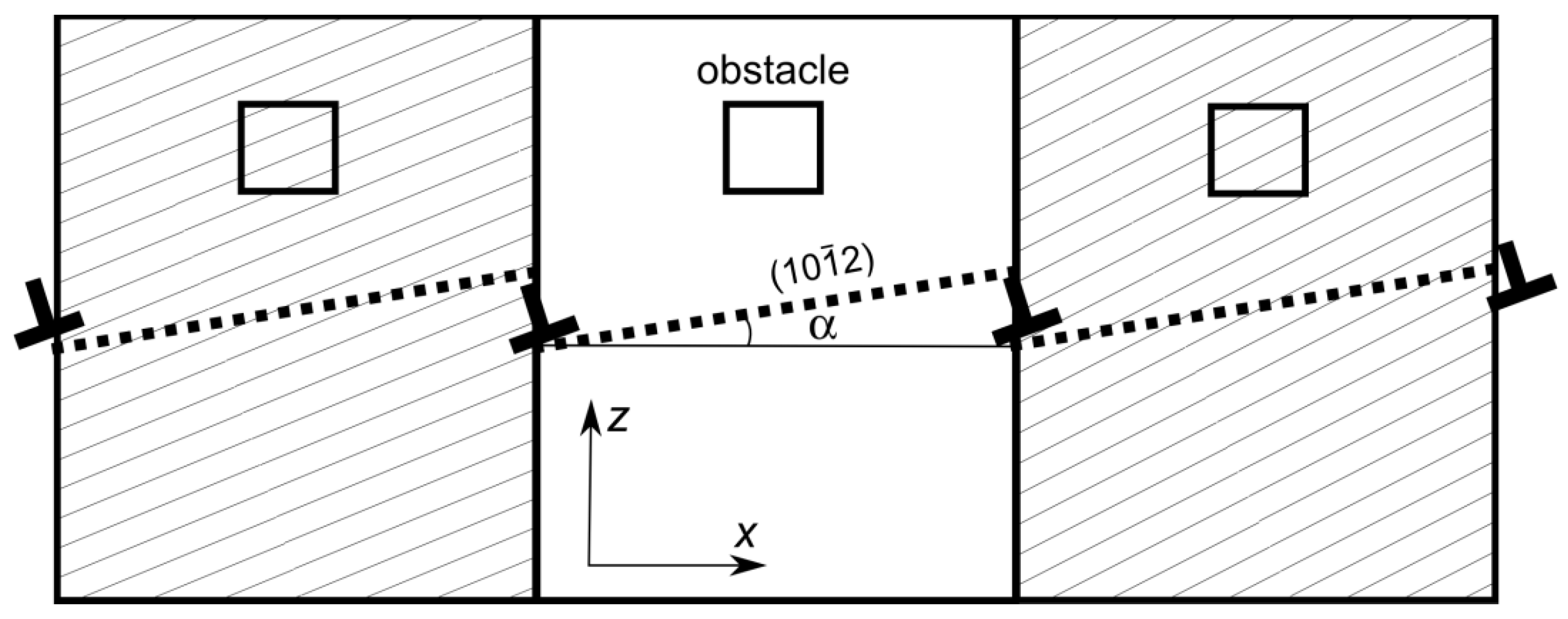
The atomistic simulations were performed by using LAMMPS (Sandia National Laboratories, Livermore, CA, USA, lammps.sandia.gov) [18] for simulations and OVITO (Darmstadt University of Technology, Darmstadt, Germany, www.ovito.org) [19] for visualization. The magnesium potential, published in Liu et al. [20], was used in the calculations. The scheme of the used simulation block is shown in Figure 1. The rectangular simulation blocks have their x-axis close to the crystal direction, y-axis along the direction, and z-axis close to normal to the plane. The x and z axes are inclined from corresponding directions by angle α. The blocks were prepared by the following procedure. The twin boundary was created inside the simulation block by the merging of crystals rotated by the misorientation angle ~86°. Then, the lattice was rotated by the angle α. The value of α was selected to satisfy the continuity of each plane through periodic boundary conditions in the x direction. Each plane is continued into the plane separated by two interplanar distances from it. Due to periodicity, steps on the twin boundary were produced at the block edges. These steps are relaxed into twinning disconnections [21,22] during energy minimization of the block. Thereby, the studied configuration contains the twin boundary with disconnections periodically placed within it.
Two different distances between disconnections (23 nm or 45 nm) were used in our simulations, and different block sizes were used in order to study the influence of the disconnection density on the twin boundary behavior. All blocks have a size of 1.9 nm in the y-direction and 50 nm in the z-direction. However, the size in the x-direction was variable. The block sizes were selected as multiples of the above-mentioned distances between disconnections (23 nm or 45 nm). The larger blocks were produced by merging of several small blocks. Consequently, the larger block contained several disconnections inside and disconnection density was preserved.
The obstacle for twin boundary migration was also inserted into the simulation block. Two types of obstacles were considered. The first one is a void with a squared shape of its xz-section and with infinite size in the y-direction. The size of void was 2 × 2 nm in the xz plane. Another type of obstacle was obtained by freezing atoms inside the selected volume. The size of the obstacle was the same as the size of the void. Such obstacle can be considered a model of non-shearable inclusion. The distance between obstacles was equal to periodicity in the x-direction. The size of obstacle was selected to be small enough in comparison to the simulation block in order to leave space for twin boundary migration between obstacles.
Shear strain (εxz) was applied to the block in order to model the interaction of the migrating twin boundary with rigid inclusion. The strain was applied in small steps, Δεxz = 0.0005. Energy minimization by the conjugate gradient method was performed after each step. The stress value of the block was monitored after energy minimization.
2.2. FE Model
FEM analysis was used to analyze the stress distribution in the vicinity of the precipitate or cavity. These stresses can describe possible preferable locations of twin nucleation and also probable twin growth.
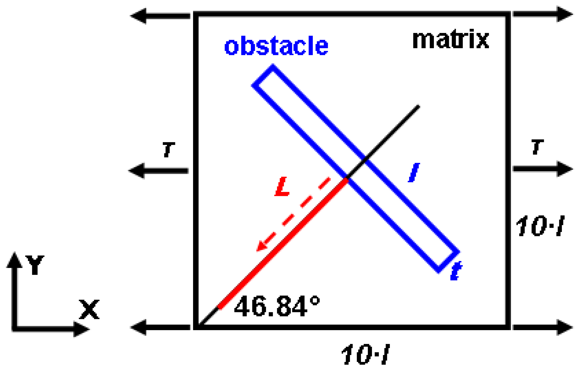
The FE model was made within the code Z-set (Mines ParisTech, Paris, France, www.zset-software.com) and its layout is provided in Figure 2. It is a 2D planar system that has a rectangular inclusion with an aspect ratio (width/length—t/l) 1/10 in the middle. The model represents an idealized case of an obstacle perpendicular to the extension twin plane which is inclined to the global X-axis. The loading and boundary conditions are applied as follows. The external tensile stress is applied in the X-direction on the vertical sides which represents tension in the crystallographic c-direction. The horizontal sides are kept straight and parallel. The length of each side is ten times the length (l) of the obstacle to avoid the influence of boundary conditions on the stresses in the obstacle vicinity. The analyzed stress is taken within the matrix along the normal axis of the inclusion (red line). The stress component that is analyzed is the shear stress along the plane.
A matrix is simulated as anisotropic elastic material with elastic constants of magnesium [23] which are summarized in Table 1. The purely elastic behavior is used to model the situation where twinning is the first inelastic deformation mode occurring prior to slip. The precipitate is isotropic elastic with Young’s modulus E = 80 GPa and Poisson’s ratio 0.35, which are the typical values used for magnesium alloys [24]. The void is simulated by a material with a very low Young’s modulus, E = 0.008 GPa. Such an approximation was chosen to keep the FE mesh identical in both cases. The “void” elastic constants are four orders of magnitude smaller than the matrix ones which makes it a valid approximation of empty space.
3. Results
3.1. Atomistic Simulations
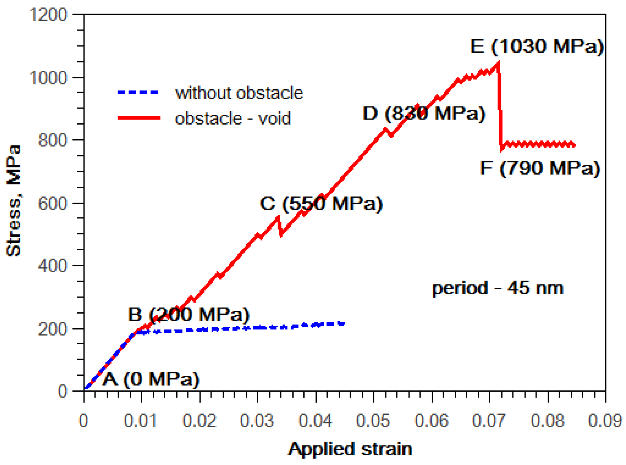
Figure 3 shows strain-stress curves for the migration of the twin boundary in the block without obstacles and for the interaction of the twin boundary with the void. The stress provided in Figure 3 is total shear stress (σxz) in the simulation block. It can be seen that the presence of the obstacle potentially inhibits twin growth. The blue curve shows continuous growth of the stress up to a value of 190 MPa. The movement of disconnections begins at this stress level. Then, the twin boundary begins to migrate continuously under practically constant stress. It is worth noting that calculations are done at 0K and no temperature effect is considered. This is the reason why the observed stress is high.
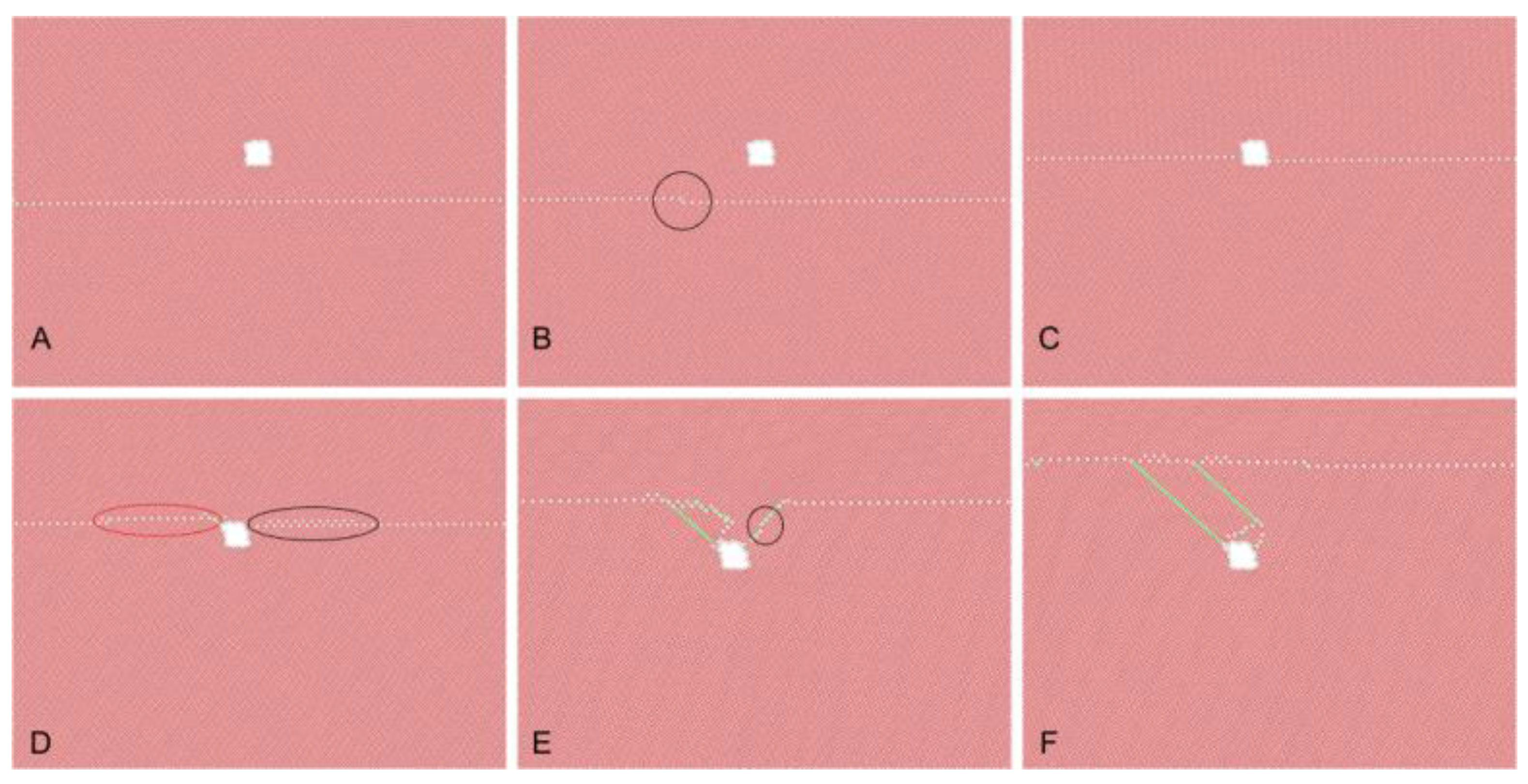
The stress increases to much higher values than 190 MPa if the void is present (red curve in Figure 3). The disconnections also begin to move at values close to 200 MPa (point B) in this case (Figure 4B). However, the presence of the obstacle leads to a further increase in the stress with the decreasing distance between the twin boundary and the cavity. After reaching the void, the twin boundary stays blocked on it (Figure 4C). The existing twinning disconnections are absorbed by the cavity surface at this moment. New disconnections begin to nucleate at the stress level 550 MPa (point C). They are also absorbed in the cavity surfaces. The twin boundary moves along the cavity during this process. It reaches the upper surface of the cavity at point D, which corresponds to the stress level 830 MPa (Figure 4D). Then, the boundary continues its migration but its stays anchored at the void. The boundary is connected to the void by segments of basal-prismatic interfaces (Figure 4E). These facets grow by ‘pile-up’ of disconnections gliding on parallel planes, similar to the case described in [25]. The point E in the stress-strain curve corresponds to the moment when basal-prismatic interfaces begin to move by nucleation of disconnection dipoles on them. This process is analogous to the process described in [22]. It happens at a considerably high stress level of 1030 MPa. A sharp decrease in the stress takes place in this moment. However, the stress does not relax completely and subsequent boundary migration takes place at the stress level of about 790 MPa. It is due to stress accumulated inside the twin, which cannot be immediately relaxed by migration of the existing twin boundary. The basal-prismatic interfaces coalesce and the twin boundary is straightened again (Figure 4F).
Figure 4E,F show configurations with migrating basal-prismatic facets and after their coalescence. The green atoms indicate neighboring, which corresponds to the fcc structure. Consequently, two basal stacking faults are nucleated during detachment of the boundary from the obstacle. These stacking faults are trailed by the migrating boundary and grow together with the twin.
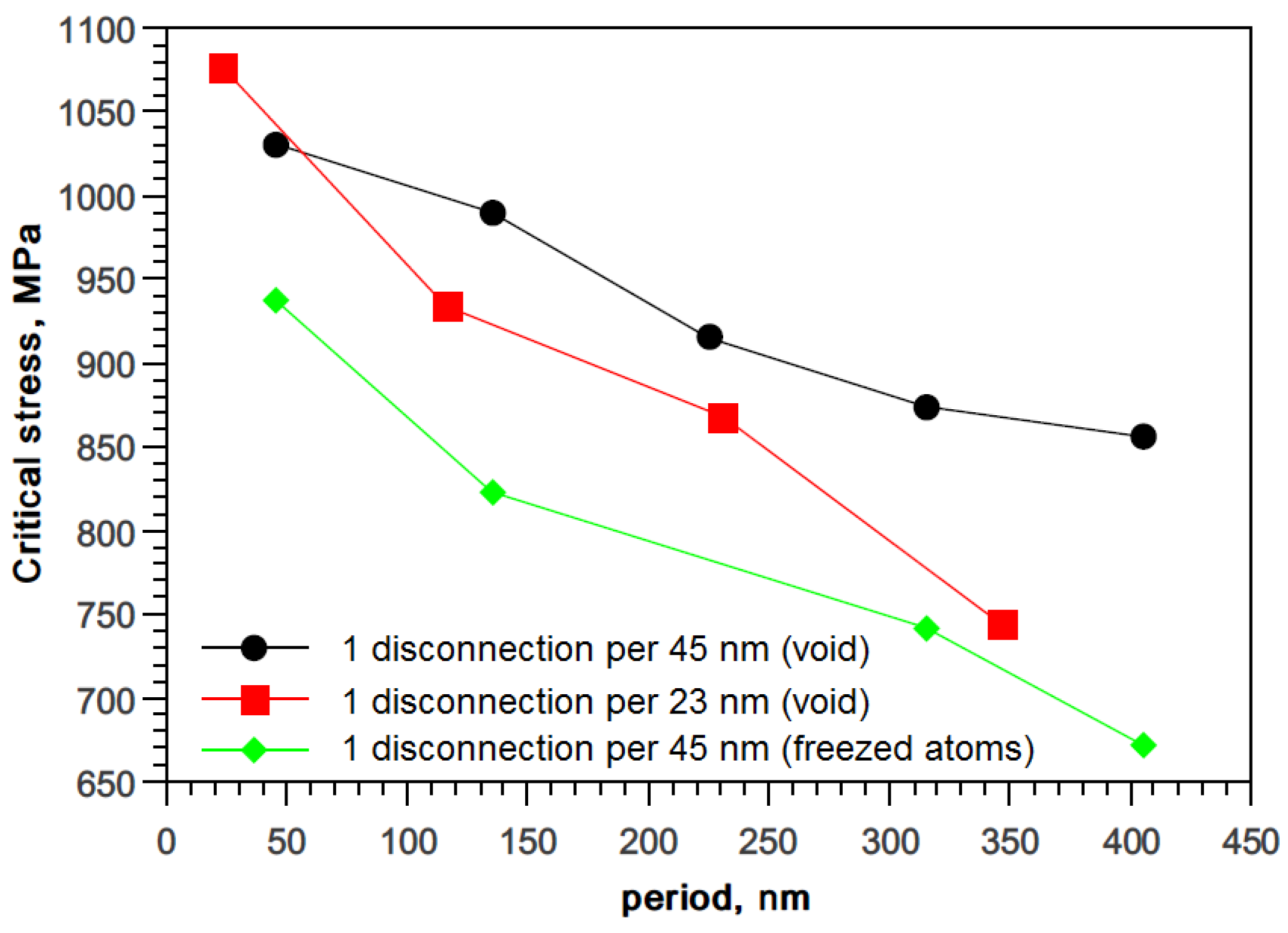
Dependences of the critical shear stress, which is necessary to push the boundary through the row of obstacles on the density of the obstacle (i.e., block size in the x direction), are shown in Figure 5. This stress corresponds to the moment when basal-prismatic interfaces begin to move (such as at point E in Figure 3). It can be seen that this stress is dependent on the type of obstacle as well as on the initial density of disconnections. It is interesting that voids serve as a stronger barrier for twin boundary migration than non-shearable obstacles.
3.2. FE Model
The relative shear stress distribution in the twin direction in the vicinity of the obstacle (along the red line in Figure 2) is shown in Figure 6. The stress is normalized by the applied external stress (τapp), and the distance (L) from the precipitate/void is normalized by its thickness (t). It is clear that the precipitate causes a slight increase in the applied stress in its close vicinity and the stress linearly decreases to the distant applied stress level. The presence of the void shows a different picture. The shear stress is zero at the boundary due to the void’s free surface. The stress increases with the distance from the void’s surface. It reaches the value for the precipitate at the distance of 2.5 of the void’s thickness and further increases to values of 1.3 of the applied stress.
4. Discussion
The stress level obtained from atomistic simulations in this study is quite high in comparison to the experimental CRSS of the twin. It is caused by the fact that existing interatomic potentials were not fitted primarily for these values. However, it is possible to expect that qualitative trends as well as atomistic mechanisms predicted by the model are correct. On the other hand, it worth noting that the experimental increase in the yield stress for the aged AZ91 alloy is at the level of about 100 MPa [26], i.e., they are comparable with our values in order of magnitude. This increase is partially caused by twin interactions with precipitates.
Our simulation revealed that the void is a stronger barrier for twin boundary migration than non-shearable obstacles. Recently, the interaction of the basal-prismatic twin boundary with the void was studied by computer simulations by Xu et al. [17]. It was demonstrated in [17] that boundary migration is hindered by the void. In contrast to our simulation, the boundary was not completely pushed through the void. However, the presence of the void led to a decrease in yield stress in comparison to boundary migration with the absence of the void. This trend is opposite to our observations shown in Figure 3, where the presence of the void led to a slight increase in yield stress. This situation is probably caused by the difference in the initial boundary configuration. In the present paper, we studied the migration of the coherent twin boundary, which already contained disconnections and was already ready to migrate. The elastic field of the void slowed down the motion of the pre-existing disconnections. However, yielding takes place by nucleation of new boundary defects and subsequent detachment of basal-prismatic segments from raw immobile misfit dislocation [17]. The stress field around the void helps in the nucleation of such defects in the basal-prismatic boundary as claimed by the authors of [17].
The FE model results correspond with the atomistic simulations. The shear stress decrease in the vicinity of the void’s surface implies that higher applied stress is needed to move the twinning boundary. Atomistic simulations show about a fivefold increase in the applied stress for initiation of boundary motion near the void (see Figure 3). Similarly, the estimated local shear stress is about fivefold lower in the close vicinity of the void’s surface in the FE model (approximately 0.25t), which suggests the necessity of an increase in the applied stress for twin initiation. In general, the void can be seen as a limiting case of a very soft precipitate, so the presented simulation shows the effect of precipitate stiffness on the local stress distribution. Soft precipitates inhibit twin boundary motion in their vicinity and increase the probability of twin initiation between precipitates due to the stress increase at this location.
5. Conclusions
Basal-prismatic facets can be formed by the glide of disconnections on parallel planes. The mechanism of their formation agrees with the existing models of twinning such as the theory of admissible interfacial defects. The basal-prismatic facet on the straight twin boundary is equivalent to a wall of twinning disconnections.
The interaction of twin boundaries with obstacles is governed by the mobility of disconnections and basal-prismatic interfaces.
The increase in critical resolved shear stress is higher for the interaction of the twin boundary with cavities than for the interaction with non-shearable obstacles.
Stacking faults can be formed by twin–twin interactions. These stacking faults can be recognized as partial stacking faults reported previously in the literature.
The continuum theory also predicts inhibition of twin boundary movement due to the significant decrease in the shear stress void’s surface.
Author Contributions
Conceptualization, A.O. and K.M.; investigation, A.O., K.K., F.Š.; writing—original draft preparation, A.O. All authors have read and agreed to the published version of the manuscript.
Funding
This research was funded by CZECH SCIENCE FOUNDATION, grant number 18-07140S, and by the MINISTRY OF EDUCATION, YOUTH AND SPORTS OF THE CZECH REPUBLIC, grant number CEITEC 2020 (LQ1601).
Institutional Review Board Statement
Not applicable.
Informed Consent Statement
Not applicable.
Data Availability Statement
Data available on request due to restrictions. The data presented in this study are available on request from the corresponding author. The data are not publicly available due to authors’ employer restrictions.
Conflicts of Interest
The authors declare no conflict of interest.
References
- Hirsch, J.; Al-Samman, T. Superior light metals by texture engineering: Optimized aluminum and magnesium alloys for automotive applications. Acta Mater. 2013, 61, 818–843. [Google Scholar] [CrossRef]
- Yoo, M.H. Slip, twinning, and fracture in hexagonal close-packed metals. Met. Trans. 1981, 12, 409–418. [Google Scholar] [CrossRef]
- Yoo, M.H.; Agnew, S.R.; Morris, J.R.; Ho, K.M. Non-basal slip systems in HCP metals and alloys: Source mechanism. Mater. Sci. Eng. 2001, A319–A321, 87–92. [Google Scholar] [CrossRef]
- Sandlobes, S.; Friak, M.; Neugebauer, J.; Raabe, D. Basal and non-basal dislocation slip in Mg-Y. Mater. Sci. Eng. A 2013, A576, 61–68. [Google Scholar] [CrossRef]
- Zhang, J.; Liu, S.; Wu, R.; Hou, L.; Zhang, M. Recent developments in high-strength Mg-RE-based alloys: Focusing on Mg-Gd and Mg-Y systems. J. Magnes. Alloy 2018, 6, 277–291. [Google Scholar] [CrossRef]
- Andritsos, E.I.; Paxton, A.T. Effects of calcium on planar fault energies in ternary magnesium alloys. Phys. Rev. Mater. 2019, 3, 013607. [Google Scholar] [CrossRef]
- Jayara, J.; Mendis, C.L.; Ohkubo, T.; Ohishi, K.; Hono, K. Enhanced precipitation hardening of Mg-Ca alloy by Al addition. Scr. Mater. 2010, 63, 831–834. [Google Scholar] [CrossRef]
- Tehranchi, A.; Yin, B.; Curtin, W.A. Solute strengthening of basal slip in Mg alloys. Acta Mater. 2018, 151, 56–66. [Google Scholar] [CrossRef] [Green Version]
- Stanford, N.; Geng, J.; Chun, Y.B.; Davies, C.H.J.; Nie, J.F.; Barnett, M.R. Effect of plate-shape particle distributions on the deformation behavior of magnesium alloy AZ91 in tension and compression. Acta Mater. 2012, 60, 218–228. [Google Scholar] [CrossRef]
- Wang, J.; Ferdowsi, M.R.G.; Kada, S.R.; Hutchinson, C.R.; Barnett, M.R. Influence of precipitation on yield elongation in Mg-Zn alloys. Scr. Mater. 2019, 160, 5–8. [Google Scholar] [CrossRef]
- Barnett, M.R.; Wang, H.; Guo, T. An Orowan precipitate strengthening equation for mechanical twinning in Mg. Int. J. Plast. 2019, 112, 108–122. [Google Scholar] [CrossRef]
- Fan, H.; Zhu, Y.; El-Awady, J.A.; Raabe, D. Precipitation hardening effects on extension twinning in magnesium alloys. Int. J. Plast. 2018, 106, 186–202. [Google Scholar] [CrossRef]
- Siska, F.; Stratil, L.; Cizek, J.; Guo, T.; Barnett, M.R. Numerical analysis of twin-precipitate interactions in magnesium alloys. Acta Mater. 2021, 202, 80–87. [Google Scholar] [CrossRef]
- Stanford, M.; Barnett, M.R. Effect of particles on the formation of deformation twins in a magnesium-based alloy. Mater. Sci. Eng. A 2009, 516, 226–234. [Google Scholar] [CrossRef]
- Wang, Y.N.; Xie, C.; Fang, Q.H.; Liu, X.; Zhang, M.H.; Liu, Y.W.; Li, L.X. Toughening effect of the nanoscale twinning induced by particle/matrix interfacial fracture on fine-grained Mg alloys. Int. J. Solids Struct. 2016, 102–103, 230–237. [Google Scholar] [CrossRef]
- Xie, C.; Wang, Y.N.; Fang, Q.H.; Ma, T.F.; Zhang, A.B.; Peng, W.F.; Shu, X.D. Effects of cooperative grain boundary sliding and migration on the particle cracking of fine-grained magnesium alloys. J. Alloys Compd. 2017, 704, 641–648. [Google Scholar] [CrossRef]
- Xu, C.; Yuan, L.; Shan, D.; Guo, B. twin boundaries migration accompanied by void in magnesium. Comp. Mater. Sci. 2020, 184, 109857. [Google Scholar] [CrossRef]
- Plimpton, S. Fast parallel algorithms for short- range molecular dynamics. J. Comp. Phys. 1995, 117, 1–19. [Google Scholar] [CrossRef] [Green Version]
- Stukowski, A. Visualization and analysis of atomistic simulation data with OVITO—The Open Visualization Tool. Modell. Simul. Mater. Sci. Eng. 2009, 18, 015012. [Google Scholar] [CrossRef]
- Liu, X.Y.; Adams, J.B.; Ercolessi, F.; Moriarty, J.A. EAM potential for magnesium from quantum mechanical forces. Modell. Simul. Mater. Sci. Eng. 1996, 4, 293–303. [Google Scholar] [CrossRef]
- Serra, A.; Pond, R.C.; Bacon, D.J. Computer simulation of the structure and mobility of twinning disclocations in hcp metals. Acta Metall. Mater. 1991, 39, 1469–1480. [Google Scholar] [CrossRef]
- Ostapovets, A.; Gröger, R. Twinning disconnections and basal—Prismatic twin boundary in magnesium. Model. Simul. Mater. Sci. Eng. 2014, 22, 025015. [Google Scholar] [CrossRef]
- Long, T.R.; Smith, C.S. Single-crystal elastic constants of magnesium and magnesium alloys. Acta Metall. 1957, 5, 200–207. [Google Scholar] [CrossRef]
- Robson, J.D. The effect of internal stresses due to precipitates on twin growth in magnesium. Acta Mater. 2016, 121, 277–287. [Google Scholar] [CrossRef]
- Ostapovets, A.; Serra, A. Characterization of the matrix–twin interface of a twin during growth. Philos. Mag. 2014, 94, 2827–2839. [Google Scholar] [CrossRef]
- Stanford, N.; Taylor, A.S.; Cizek, P.; Siska, F.; Ramajayam, M.; Barnett, M.R. twinning in magnesium-based lamellar microstructures. Scr. Mater. 2012, 67, 704–707. [Google Scholar] [CrossRef]
Figure 1.
Scheme of the simulation block. The dashed line corresponds to the twin boundary. Shaded areas are periodic images of the central block. Twinning disconnections produce steps on the twin boundary due to periodic boundary conditions.
Figure 1.
Scheme of the simulation block. The dashed line corresponds to the twin boundary. Shaded areas are periodic images of the central block. Twinning disconnections produce steps on the twin boundary due to periodic boundary conditions.

Figure 2.
The FE model geometry, with loading conditions and location for stress analysis (red line). The size of the obstacle is not to scale.
Figure 2.
The FE model geometry, with loading conditions and location for stress analysis (red line). The size of the obstacle is not to scale.

Figure 3.
Strain-stress curves for the case of twin boundary migration in the block without the obstacle (blue line) and in the block containing the void (red line).
Figure 3.
Strain-stress curves for the case of twin boundary migration in the block without the obstacle (blue line) and in the block containing the void (red line).

Figure 4.
Interaction of the migrating twin boundary with the void: (A) initial configuration; (B) migration of the pre-existing disconnection along the boundary. The disconnection is marked by a black circle; (C) the boundary is blocked in the void; (D) nucleation of disconnection dipoles in the boundary and subsequent absorption of disconnections by the void surface; The dipoles are marked by ellipses. The red ellipse marks the already developed dipole and the black ellipse marks the location of dipole nucleation in progress. (E) formation and migration of basal-prismatic interfaces. Disconnection on the basal-prismatic interface is marked by a circle; (F) detachment of the boundary from the void with the formation of two basal stacking faults. The projection of the figure is in the direction. The atoms in the boundary are colored in white and atoms in stacking faults are colored in green.

Figure 5.
Dependence of critical stresses on the distance (period) between obstacles for different densities disconnections and kinds of obstacle (cavity or non-sheared obstacles).
Figure 5.
Dependence of critical stresses on the distance (period) between obstacles for different densities disconnections and kinds of obstacle (cavity or non-sheared obstacles).

Figure 6.
Stress distribution inside the matrix in the direction of the precipitate/void normal axis. Shear stress is normalized by externally applied stress τapp and distance L is normalized by precipitate/void thickness t.
Figure 6.
Stress distribution inside the matrix in the direction of the precipitate/void normal axis. Shear stress is normalized by externally applied stress τapp and distance L is normalized by precipitate/void thickness t.


Table 1.
Elastic constants of Magnesium.
| Tensor Component | Value [GPa] |
|---|---|
| C1111 | 59.7 |
| C2222 | 59.7 |
| C3333 | 61.7 |
| C1212 | 16.8 |
| C2323 | 16.4 |
| C3131 | 16.4 |
| C1122 | 26.2 |
| C2233 | 20.8 |
| C3311 | 20.8 |
Publisher’s Note: MDPI stays neutral with regard to jurisdictional claims in published maps and institutional affiliations. |
© 2021 by the authors. Licensee MDPI, Basel, Switzerland. This article is an open access article distributed under the terms and conditions of the Creative Commons Attribution (CC BY) license (http://creativecommons.org/licenses/by/4.0/).
Share and Cite
MDPI and ACS Style
Ostapovets, A.; Kushnir, K.; Máthis, K.; Šiška, F. Interaction of Migrating Twin Boundaries with Obstacles in Magnesium. Metals 2021, 11, 154. https://0-doi-org.brum.beds.ac.uk/10.3390/met11010154
AMA Style
Ostapovets A, Kushnir K, Máthis K, Šiška F. Interaction of Migrating Twin Boundaries with Obstacles in Magnesium. Metals. 2021; 11(1):154. https://0-doi-org.brum.beds.ac.uk/10.3390/met11010154
Chicago/Turabian StyleOstapovets, Andriy, Konstantin Kushnir, Kristián Máthis, and Filip Šiška. 2021. "Interaction of Migrating Twin Boundaries with Obstacles in Magnesium" Metals 11, no. 1: 154. https://0-doi-org.brum.beds.ac.uk/10.3390/met11010154
Note that from the first issue of 2016, this journal uses article numbers instead of page numbers. See further details here.