Article

Influence of Feed Rate Response (FRR) on Chip Formation in Micro and Macro Machining of Al Alloy

1
Department of Mechanical and Production Engineering, Ahsanullah University of Science and Technology, Dhaka 1208, Bangladesh
2
Industrial Engineering Department, College of Engineering, King Saud University, P.O. Box 800, Riyadh 11421, Saudi Arabia
3
Department of Manufacturing Technology, Le Quy Don Technical University, 236 Hoang Quoc Viet, Ha Noi 100000, Vietnam
4
Advanced Manufacturing Laboratory, Institute of Infrastructure Technology, Research and Management, Ahmedabad 380026, India
5
Department of Mechanical Engineering, IKG Punjab Technical University, Jalandhar-Kapurthala Road, Kapurthala, Punjab 144603, India
6
Key Laboratory of High Efficiency and Clean Mechanical Manufacture, Ministry of Education, School of Mechanical Engineering, Shandong University, Jinan 250061, China
7
Department of Mechanical Engineering, Imperial College London, London SW7 2AZ, UK
*
Author to whom correspondence should be addressed.
Submission received: 28 November 2020 / Revised: 31 December 2020 / Accepted: 5 January 2021 / Published: 16 January 2021

Abstract

:
In this paper, the investigation of chip formation of aluminum alloy in different machining strategies (i.e., micro and macro cutting) is performed to develop a holistic view of the chip formation phenomenon. The study of chip morphology is useful to understand the mechanics of surface generation in machining. Experiments were carried out to evaluate the feed rate response (FRR) in both ultra-precision micro and conventional macro machining processes. A comprehensive study was carried out to explore the material removal mechanics with both experimental findings and theoretical insights. The results of the variation of chip morphology showed the dependence on feed rate in orthogonal turning. The transformation of discontinuous to continuous chip production—a remarkable phenomenon in micro machining—has been identified for the conventional macro machining of Al alloy. This is validated by the surface crevice formation in the transition region. Variation of the surface morphology confirms the phenomenology (transformation mechanics) of chip formation.

1. Introduction

Machining lightweight materials (like Al alloy) is an important manufacturing process in the automobile and aerospace industries [1]. Moreover, the micro machining of Al alloy is gaining importance due to the increased applications in precision micro industries [2]. The machinability of an alloy mainly depends on its material status (i.e., microstructure defects, physical and mechanical properties) and machining environment (i.e., machine tool, cutting parameters, cutting tool geometry) [3,4]. Thus, the machinability of a material plays a crucial role in determining various applications and requirements [5]. Machining force, power consumption, surface finish, chip shape, and size are often used for the evaluation of machinability [6].
Properties such as low weight/strength ratio, good formability, high mechanical strength, improved fatigue performance, and fracture toughness have made aluminum alloys widely applicable in the aeronautic [7,8] and automotive industries [9]. For example, Al 6061 is used for car wheels, panels, and structures [9]. Silicon carbide hard particle reinforced Al 6061 is used for pistons, brake discs and drums, piston sleeves [10,11]. Al 6082 is used in transport applications [12]. Al 7050-T7451 is used for aircraft structure [13]. Al 7075-T6 is used for fittings, gears, and shafts [14,15]. Al 2024-T3 is used for aircraft skin [16]. Up to 2050, the demand for aluminum alloy expected to grow between a factor of 2.6 to 3.5 [17]. Concomitant to this growing demand, a significant surge of the processing of aluminum alloys prevails in automotive and aerospace industry where material removal by machining plays a vital role in the shaping of the Al alloy components [18]. Hence, a deeper perception of the machinability assessment of Al alloys is essential for making proper decisions about Al alloy machining process [19]. Therefore, an insightful understanding of the material removal mechanism in terms of cutting parameter and chip morphology will play an important role in the widespread applications of aluminum alloy.
Moreover, dry machining is widely adopted in industries as a sustainable manufacturing process by the elimination of the cutting fluids that are harmful to the environment [20]. Furthermore, tool-based machining is considered one of the key technologies for the miniaturization of parts used in various industrial sectors [21]. Therefore, precision micromachining, such as milling, drilling, and turning, is utilized for microscale material removal to manufacture the high-quality micro sized components [22]. For example, Al alloy thin-walled micro-channels and micro-impellers were fabricated by dry micro milling [23,24], micro-holes were created by micro drilling on Al alloy sheets [25], surface generated [26], and micro rod fabricated [2] by micro turning of the Al alloy. Although the tool-based micromachining technologies are the miniaturized versions of conventional material removal process, the mechanics of micro and macro machining requires deeper study to explore the material removal process further [27].
The arrangement of a workpiece and single point cutting tool in orthogonal machining is depicted in Figure 1a [28], where the feed is provided to the cutting tool. The ideal tool is assumed with a sharp edge to plastically deform the material to remove as a chip by the shearing mechanism. AB represents the shear zone which is inclined at an angle φ (shear angle) to the horizontal as illustrated in Figure 1b [29]. The layer of material to be removed is denoted as undeformed chip thickness, UCT (hc), while the deformed chip thickness is denoted as ho. In micromachining operations, the undeformed chip thickness (hc) may be comparable to the size of cutting edge radius, CER (r) and hence, cutting edge can no longer be considered sharp as illustrated in Figure 1c [30]. To analyze the material flow in micro cutting, the stagnation point (S) is considered on the cutting edge of the tool; above this point a chip is formed and below only the elastic-plastic deformation takes place [31,32]. As the undeformed chip thickness (hc) reduces in micromachining, the positive rake angle of the tool (+γtool), shown in Figure 1d [33], is not the actual rake angle participating in the material removal process. The effective rake angle becomes negative (−γeff) as the value of UCT (hc) reaches much smaller than the size of CER (r). In this instance, the cutting edge plastically deforms the workpiece material, as described by the ploughing mechanism in micromachining [34]. Thus, in order to achieve stable chip formation and increase material removal rate (MRR) during machining, the UCT (hc) should reach an optimum value.
Therefore, micro-cutting is fundamentally different from macro cutting, due to the variability in process mechanics resulting in distinct chip-formation [35]. The well-known “shear plane model” explains the macro cutting, where the material is removed by shear deformation. However, the micro-cutting mechanism is influenced by the cutting edge geometry as the UCT (hc) becomes smaller than CER (r). Thus, both CER (r) and UCT (hc) have a significant impact on the chip formation and surface generation mechanisms that require in-depth study. While basic knowledge on the concentrated shearing mechanism to ‘extrusion-like’ deformation mechanism [36] and material ploughing [37] is available, an in-depth study on the chip morphology is still lacking in the literature. In micro-milling, the transition from chip formation to sliding/rubbing phase is predicted for Inconel 718 with the ratio of UCT (hc) and CER (r) [38]. Again, with a change of UCT (hc) from below to above the size of CER (r), the formation of discontinuous, transitional and shear localised chips observed for Inconel 718 [39]. Furthermore, the micro milling of additively fabricated material (Inconel 625) renders shearing, transition, and ploughing behavior on a specific cutting force as feed per tooth is reduced [40]. Similar material removal behavior reported for additively manufactured steel (17-4 PH), with the transition from shearing to ploughing regime at minimum uncut chip thickness [41].
Moreover, the material microstructure and chip formation characteristics affect the machined surface quality when the machining process is scaled down from macro to micro/nano level [42]. As the chip formation is a vital phenomenon in metal cutting, due to its effect on the surface finishing and part accuracy [43], this has raised the research interest in the episodes of chip formation mechanics in machining. In a previous micro turning study with Al alloy, the influence of machining parameters (depth of cut, spindle speed, and feed rate) on the variations of chip morphology was shown [19]. Micro- and nano-scale machining of aluminum 7075-T6 showed the dependence of machining forces, chip geometry, surface roughness, specific cutting energy, shear angle, and friction coefficient on the undeformed chip thickness [44]. The machining results were analyzed with respect to the cutting edge radius effect, and observed trends were compared with conventional macro-scale cutting. However, the effects of feed rate on chip formation were missing. A recent study of conventional longitudinal turning with Mg-Al alloy has shown that feed rate has the most significant impact on surface roughness and machined chip shape [45]. Moreover, the influence of feed rate on chip morphology in conventional macro turning of AA6061-T6 alloys investigated through FEM simulations [46]. However, the detailed study on the structural change of the Al alloy chip surface with feed rate is lacking in the literature. This paper is intended to fill this research gap. Thus, the objective of this study is to investigate the effect of feed rate on the change of chip surface structure—both in the micro and macro machining of Al alloy.

2. Material and Experimental Method

2.1. Workpiece, Cutting Tool and Machine Tool

Figure 2 shows the workpiece and cutting tool for the micro and macro machining experiments. A hollow cylinder of Al alloy (96.5% Al, 1% Mg, 1.8% Si), with an outside diameter (OD) of 50 mm and a wall thickness of 1 mm, was used as a work piece and the CBN(cubic boron nitride) insert of 15.2 μm cutting edge radius (r) was used as a cutting tool (see Figure 2a,e,g). An ultra-precision lathe machine, Toshiba ULG-100C(H3) (Shizuoka-ken, Japan) was used for the micro turning process. The machine is manufactured with a high precision air bearing spindle, and guideways to maintain process reliability in temperature-controlled and vibration resistant surroundings. The machine tool has optical scales with 1 nano-meter position resolution and a maximum spindle rpm of 1500. The material microstructure and cutting scheme is shown in Figure 2c,d.
For conventional macro machining, a hollow cylinder of Al alloy with OD 45 mm and wall thickness of 7 mm was used as a workpiece and the P-type carbide insert of 477.7 μm cutting edge radius (r) was used as a cutting tool (see Figure 2b,f,h). Macro machining experiments were conducted on a horizontal engine lathe manufactured by Shanghai Shenji International Company Limited (Model CS6266B) (Shanghai, China), with a maximum spindle rpm of 1600. The experiments were designed to keep cutting speed constant while varying the feed rate to evaluate the feed rate response (FRR) in micro and macro cutting. The cutting tool, machine tool, and machining parameters are listed in Table 1.

2.2. Methods of Machining Experiments

An orthogonal micro turning test was conducted on the 1-mm wall thickness of the Al alloy workpiece with the straight cutting edge of the CBN insert, as per the cutting scheme shown in Figure 2e. This was carried out at a constant cutting speed of 100 m/min (spindle speed at 636 rpm), and the feed rate was varied in the range of 1.61–96.72 μm/s to realize six different feed ratios (feed/lowest feed), as listed in Table 1.
The orthogonal macro turning of the workpiece was undertaken with the carbide insert on the wall thickness of 7 mm, as per the cutting scheme illustrated in Figure 2e. At a constant cutting speed of 70.6 m/min (spindle speed at 500 rpm), the feed rate was varied in the range of 0.75–1.50 mm/s to realize the different feed ratios (FR), as listed in Table 1, for the variation of machining mechanics and, hence, the chip formation characteristics in macro/conventional turning.

3. Experimental Results

3.1. Chip Morphology in Micro Machining

Al alloy microchips produced at different feed rates exhibited different characteristics, as shown in the optical images Figure 3. ‘Debris-like’ chips produced at a feed rate of 1.61 μm/s clearly renders incomplete, irregular, and discontinuous shapes. The increased feed rate to 3.22 µm/s shows the chip surface with the presence of micro cracks and holes. The increment of feed rate to 12.90 μm/s shows the spiral chip formation without micro crack/holes on the chip surface. Chips at a feed rate of 16.12 μm/s and 64.48 μm/s show the curly shape. The long and continuous type of chip was observed for an Al alloy at 96.73 μm/s. Thus, incomplete-punctured chip formation at micron (≈1 µm/s) feed rate and complete-long chip formation at high feed rate (>>1 µm/s) are distinguished as the significant chip formation characteristics in micro machining. However, the optical image in Figure 3 does not reveal the significant characteristics of the microchips produced at different low to high feed rates.
Thus, micromachined chips were analyzed in a scanning electron microscope (SEM). Distinct chip structures were observed from the SEM image of the microchips, as shown in Figure 4. ‘Debris-like’ microchips produced at a very small feed rate of 1.61 μm/s, due to the rubbing mechanism that resulted in incomplete and discontinuous chip formation [47]. These debris-like chips are not clearly visible to the open eye, as illustrated in Figure 3. Moreover, a lower magnification of SEM image does not reveal the comprehensive material deformation characteristics, as depicted in the ×250 magnification image (in Figure 4). This necessitates higher magnification (×1000) SEM image analysis of the microchips.
As shown in Figure 5, a smaller feed rate of 1.61 µm/s, the higher SEM magnification image (×1000) shows deformed material of the top (free) surface of the microchip produced as ‘grid-like’ structure. At this feed rate, the value of the uncut thickness of the chip (hc = 0.152 μm) becomes much smaller than the cutting edge radius (r = 15.2 μm), and thus, high pressure is created in front of the cutting edge, causing high compressive stress [48]. In this instance, the CBN tool encountered higher friction, as it rubbed the workpiece material, and thus, irregular discontinuous chips were produced. This is akin to micro-grinding at relatively small UCT conditions when the workpiece surface is subjected to the elastic-plastic deformation [49].
Increasing the feed rate to 12.90 μm/s resulted in a ‘quasi-lamellar’ or partially lamellar structure with numerous micro-holes on the μ-chips surface, as shown in Figure 5. The morphology of chips at this stage is influenced by the cutting edge radius effect dominated by the severe hydrostatic pressure, which deforms the material [50]. This is due to the occurrence of stagnation point (S) on the cutting edge of the tool; the material above the stagnation point moves to form the microchip, but the material below the stagnation point is depressed to form the machined surface [51]. Therefore, the stagnation point acts for material flow branching, as illustrated in Figure 1c. Thus, near to the stagnation region partly incomplete chips with micro-holes occur. An increase to the higher feed rate of 96.73 μm/s rendered continuous chips with regular lamella formation. This is due to the higher feed rate when the material ahead of the tool is moved in the direction of cutting and thus, a shear band is created [52]. By the successive rotation of the workpiece with tool feed, lamellar chip is formed, in accordance with Merchant’s shearing model [53]. Hence, the work material is removed by conventional shearing mechanism resulted in the formation of long continuous chips.
Moreover, closer SEM examination of top (free) surface or unrestricted surface of Al alloy chip at small feed rate (1.61 µm/s) renders grain-induced plastic instability, as shown in Figure 6a. The ‘grid-like’ structure suggests that individual grains undergo differential deformation due to the heterogeneity in mechanical properties of grains [54]. This is substantiated from the material deformation-like mechanism [55] observed at ×10,000 magnification of the SEM image. Thus, material deformation is the perceived characteristic of chip formation at small feed rate. On the other hand, free surface of Al alloy chip at a large feed rate (96.73 µm/s) shows lamella-like structure typically produced by shearing mechanism [56], as shown in Figure 6b at ×10,000 magnification of the SEM image.

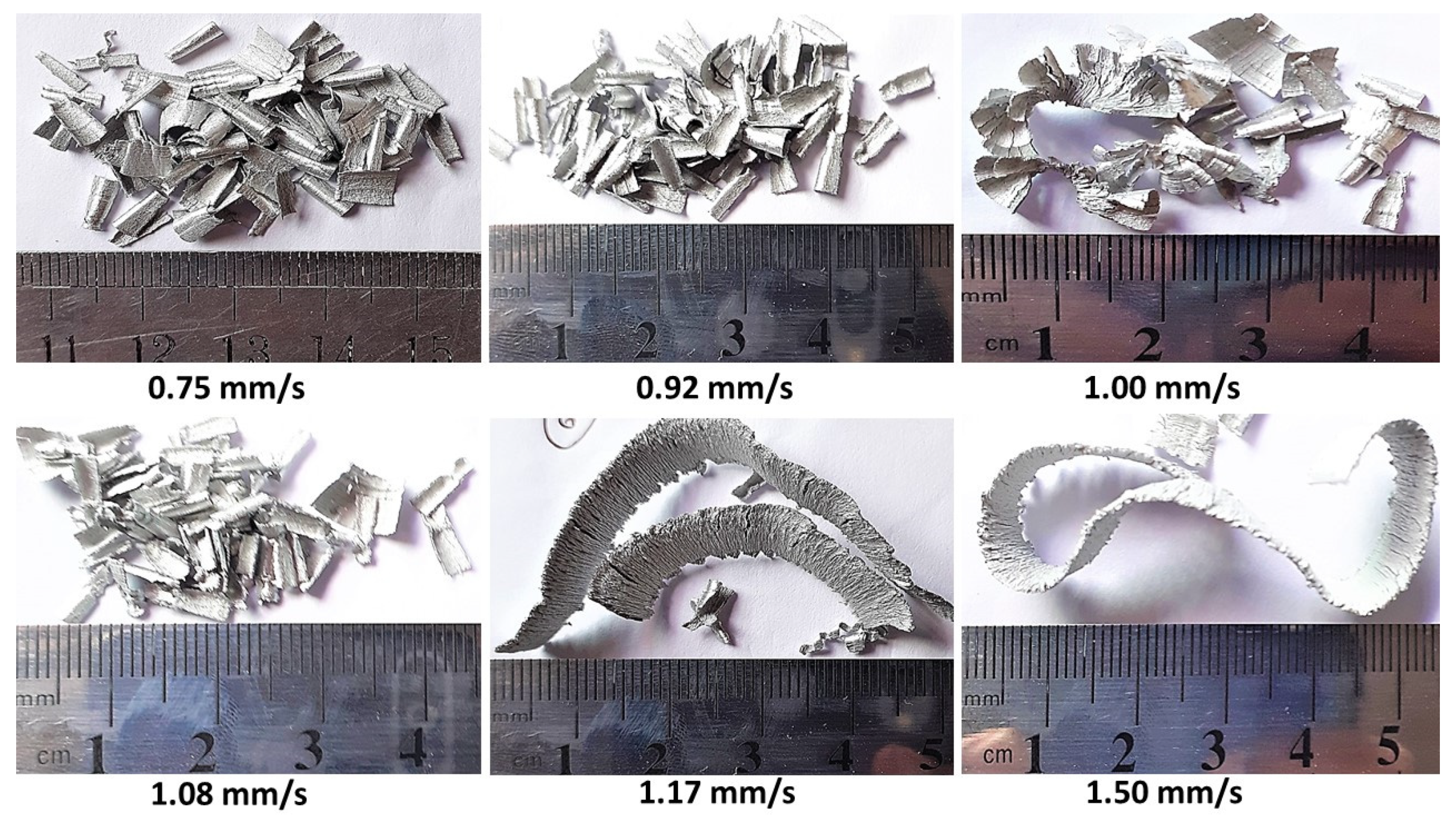
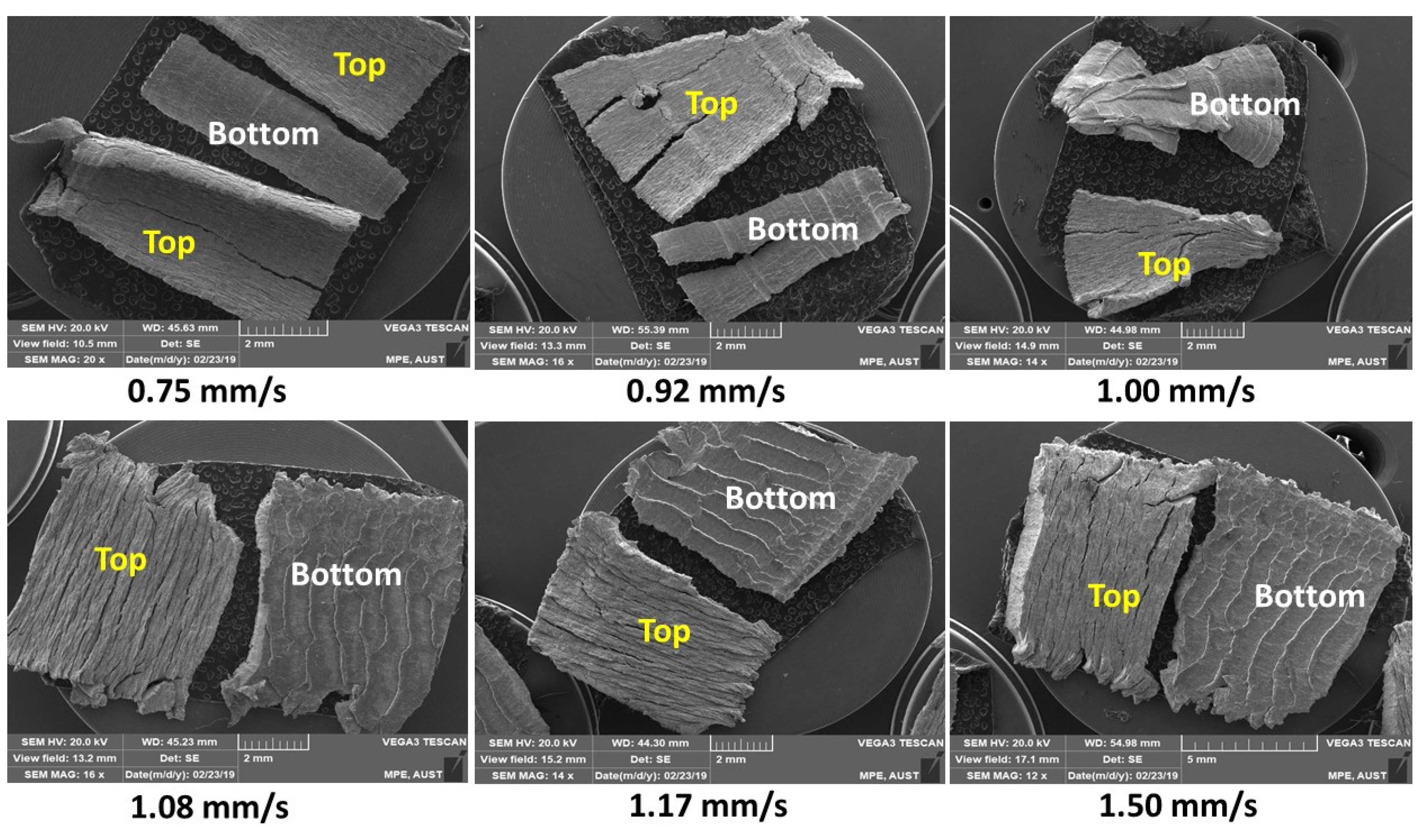
3.2. Chip Morphology in Macro Machining

Reportedly, the cutting speed does not significantly affect the chip morphology on the periodicity of shear fronts [57]. Hence, Al alloy macrochips produced at a constant cutting speed 70.6 m/min (500 rpm), with different feed rates exhibiting different characteristics, as shown in the optical image in Figure 7. Chips obtained at small feed rate of 0.75 mm/s and 0.92 mm/s clearly render incomplete and discontinuous shapes. An increased feed rate to 1.00 mm/s shows the chip structure with visible cracks on the surface. An increase of feed from 1.08 mm/s to 1.50 mm/s produced the lamellar structure on the top (free) surface of chips. Moreover, discontinuous chip formation at a lower feed rate (≤0.92 mm/s) and continuous chip formation at a higher feed rate (≥1.17 mm/s) were distinguished as the significant chip formation characteristics in macro machining in a conventional lathe machine. However, the optical image in Figure 7 does not reveal the significant characteristics of the macrochips produced at different feed rates.
The morphology of the macrochip reveals distinct chip structures observed from the analysis of SEM image of the chip top (free) surface, as shown in Figure 8. Macro chip surfaces of Al alloy, produced at smaller feed rate (0.75 mm/s), are not distinguishable to the open eye, as illustrated in the optical image (in Figure 7). Moreover, a lower magnification of SEM image does not reveal the comprehensive material deformation characteristics as depicted in Figure 8.
Thus, a larger magnification (×1000) SEM image analysis of the top (free) surface of the macro chips was conducted, as shown in Figure 9. At a smaller feed rate (0.75 mm/s), a higher SEM magnification image (×1000) shows the material deformation characteristics of the free surface of macro chip, which exhibited numerous cracks, similarly observed as brittle fracture of A356-T0 cast Al alloys [58]. An increased feed rate to 1.00 mm/s, ‘surface crevice’ generation on the lamellar structure was observed, as shown in Figure 9. The morphology of chips at this stage is influenced by the change of feed rate. At a higher feed rate of 1.50 mm/s, the continuous chip with regular lamella formation was observed, similar to the conventional machining (shaping) of Al-Si alloys [59].

4. Analysis and Discussion

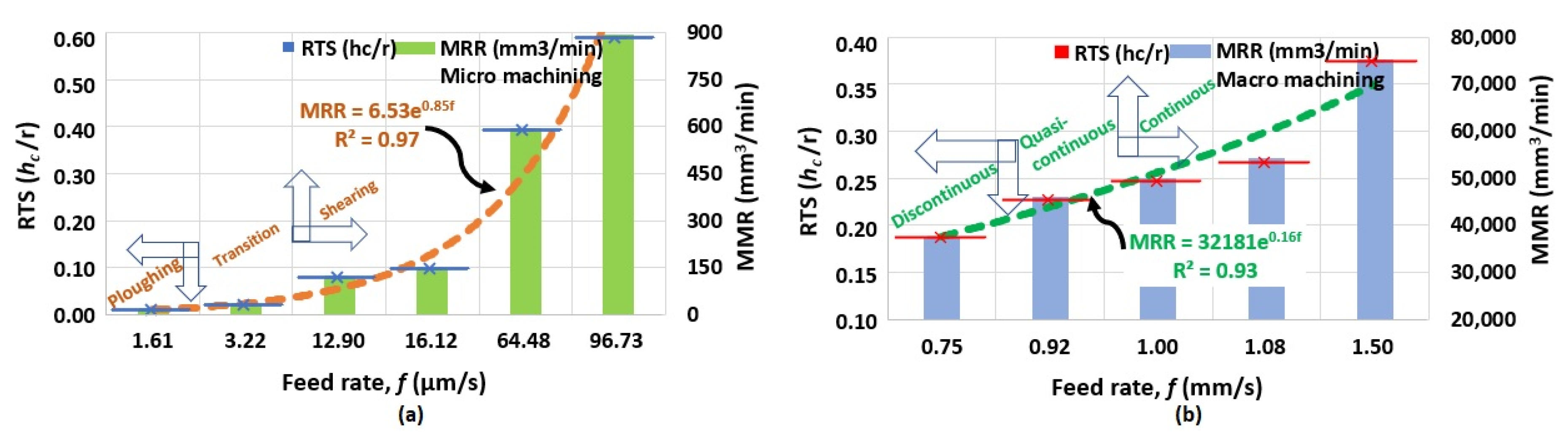
4.1. Material Removal Rate and Relative Tool Sharpness (RTS)

The influence of the cutting edge radius has been emphasized by the role of the relative tool sharpness, RTS (hc/r), the ratio of undeformed chip thickness (hc) and edge radius (r) of the cutting tool, as a dominant parameter that affect the chip formation in micro machining [60]. Additionally, the postulation of RTS has also appeared to be a pivotal ratio, below which the chip formation transits from shearing (cutting) to ploughing dominated, where chips do not form effectively, but elastic-plastic deformation happens [61]. This section, thus, discusses the combined effect of RTS, feed rate (f), and material removal rate (MRR) on the chip formation mechanics for micro and macro machining.
The undeformed chip thickness is correlated to the tool feed rate, work piece diameter, and cutting speed, as per the below Equation (1):
h c = π × 60 × O D × f V × 1000
where undeformed chip thickness, UCT (hc) in µm (micro machining) or mm (macro machining), work piece diameter (OD) in mm, tool feed rate (f) in µm/s (micro machining) or mm/s (macro machining), and cutting speed (V) in m/min.
Additionally, the material removal rate is correlated to the tool feed rate, work piece diameter, and cutting speed, as per the below Equation (2):
M R R = π 2 × ( O D 2 I D 2 ) × f z × N 4 × 1000
where material removal rate, material removal rate (MRR) in mm3/min, tool feed rate (fz) in µm/rev, OD and ID are work piece outer and inner diameter in mm and N is rotation in rev/min.
Using Equations (1) and (2), UCT (hc) and MRR are calculated from the machining parameters. Figure 10a shows the influence of feed rate (f) on the RTS and MRR in the micro machining of Al alloy. At a lower feed rate of 1.61 μm/s, the UCT (hc) becomes 0.152 μm, which provides the RTS (hc/r) value of 0.01, making the undeformed chip thickness 1% of cutting edge radius (r = 15.2 μm). At this extremely small UCT (hc), chip formation is not efficient due to the ‘size effect’, which causes the transition of cutting into ploughing/sliding-like behavior [62]. Consequently, MMR becomes smaller, as shown in Figure 10a. On the other hand, an increased feed rate gives rise to the UCT and RTS. This has increased the MRR similarly observed for micro milling of Al alloy 6063 T6 with an increased feed rate [63].
The effect of the feed rate on RTS and MMR in macro machining is illustrated in Figure 10b. With the lower feed rate of 0.75 mm/s, the UCT (hc) becomes 90 μm, which renders the value of RTS (hc/r) 0.188, making the UCT 18.8% of the cutting edge radius (r = 477.7 μm). In this condition, material is removed in the form of chips, as shown from the MRR value of 37,620 mm3/min. An increased feed rate increases RTS and MRR, similar to that observed for conventional turning processes [64].
Figure 10 is useful to predict the MRR from the feed rate (f) with the regression model for micro and macro machining. The coefficient of determination R2 > 97% (micro machining) and R2 > 93% (macro machining) reveals the fitness of the model. It can be inferred that the predictive models are very close to the experimental results. This is substantiated by the phenomenology of chip formation in micro machining (ploughing, transition, and shearing) and macro machining (discontinuous, quasi-continuous and continuous).

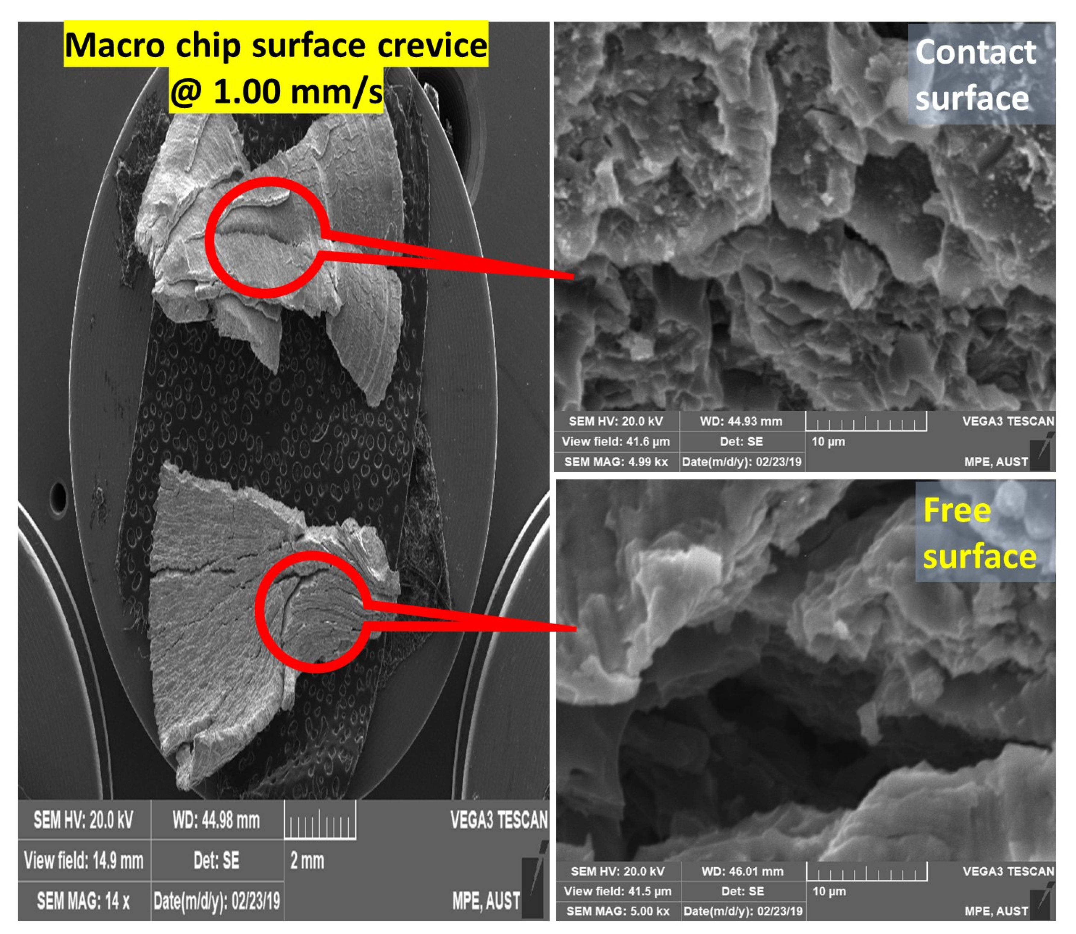
4.2. Phenomenology of Surface Crevice Formation

The phenomenology of microchips (Figure 3, Figure 4 and Figure 5) revealed that at smaller feed rates, incomplete and discontinuous chip formation resulted from irregular material deformation on the microchip. At a feed rate of 1.61 μm/s, the RTS (hc/r) becomes 0.01 when UCT (hc) occupies 1% of CER (r) in the tool-workpiece interaction during the microchip formation. The subsequent increase of the feed rate caused the increment of uncut chip thickness to reach the level of the minimum value of chip thickness to remove the material [65]. Thus, the increased feed rate to 12.90 μm/s, the RTS (hc/r) becomes 0.08 when the engagement of UCT (hc) to CER (r) increases to 8%, activates the edge radius effect due to the occurrence of material separation near the stagnation point (S), as illustrated in Figure 1c. In this instance, the formation of a ‘quasi-lamellar’ or non-uniform lamellar structure with a micro hole like surface crevice on an Al alloy microchip was noticed, as shown in Figure 11. The crevice on the microchip surface, produced in the ‘transition regime’ at feed rate 12.90 μm/s, was analyzed through ×5000 magnification SEM image. Although the micro crevice and micro hole in the microchips were observed in SEM pictures of deformed chips of carbon steel [66], Cu, and Mg alloy [60], the actual mechanism of such a crevice-like formation was not reported. In this study, Al alloy microchip formation is found to be influenced by the cutting edge effect near to the stagnation region (Figure 1c) as an intermediate feed rate. Thus, the micro hole formation is due to the transience caused by the initiation of the surface crevice when the UCT reaches certain percentage of CER(r) in the ‘transition regime’, is illustrated in Figure 5. At higher feed rate of 96.73 μm/s, the RTS (hc/r) becomes 0.60 when UCT (hc) engages 60% of CER (r), the continuous chips are produced by shearing mechanism.
The phenomenology of macro chips (Figure 7, Figure 8 and Figure 9) at a small feed rate of 0.75 mm/s revealed material deformation on the chip surface. An increase in the feed rate to 1.00 mm/s shows no systematic segmentation behavior. The formations of brittle microcracks were noticed from the ×5000 magnification of the SEM image as shown in Figure 12. The material is difficult to deform in the shear zone, as the material resists deformation, and thus, the surface crevice is noticed as similarly observed in [58]. A ×5000 times magnification of the surface crevice reveals a micropore-like formation, as shown in Figure 12. The phenomenon of micro crevice could be due to the initiation of the rift, which subsequently de-laminates the material from the surface similarly observed in micro machining. Thus, the crevice formation on the chip surface, a remarkable phenomenon observed in micro cutting is also noticed in macro cutting in the ‘transition regime’, as the feed rate is increased from a low to medium value. An increase to a high feed rate of 1.50 mm/s provided the continuous chips by shearing mechanism, similarly observed for the machined chip surface of an Al-Si alloy [59].

4.3. Chip Tool Contact Length and Effective Rake Angle

The deformed chip thickness (ho) of Al alloy micro and macro chips at different feed rates were measured from the SEM image, as shown in Figure 13a,b. The increasing trend of chip thickness (ho) is found with the increment of feed rate for both micro and macro machining, due to the increase of UCT (hc).
The shear plane length, AB (Lc), shown in Figure 1b, is computed from the classical mechanics of shear plane theory [67] as per the below Equation (3):
L c = h c sin φ
The shear plane angle (φ) is calculated from Equation (4):
φ = tan 1 [ ( h c h o ) cos γ e f f 1 ( h c h o ) sin γ e f f ]
where the effective rake angle (γeff) is calculated from the ratio of UCT (hc) and cutting edge radius (r) [68] from Equation (5):
γ e f f =   sin 1 [ ( h c r ) 1 ]
Equations (3)–(5) were used to calculate the length of the shear plane (Lc) and effective rake angle (γeff) from the experimental results, as shown in Figure 14a,b.
As shown in Figure 3, lowering RTS (hc/r) to an extremely small value renders fragmented chips formation [69], where the governing mechanism is related to the ploughing-like action [70]. In this condition, the material removal could not be performed effectively with large effective −γeff, due to the reduced contact of the chip surface with the cutting tool edge [69].
In micro machining at a large feed rate of 96.73 µm/s, the shear plane angle (φ) becomes 9.75°, which provides the length of shear plane (Lc) as 53.86 µm. In this condition, the effective rake angle (γeff) becomes −23.57° as shown in Figure 14a. Reducing feed rate reduces the φ value, which subsequently reduces the Lc due to the reduction of chip tool contact length. As a result, enormously large effective negative rake angle produced (γeff = −81.86° at feed rate of 1.61 µm/s) activating a ploughing-like mechanism.
Moreover, in macro machining with large feed rate of 1.50 mm/s, the shear plane angle (φ) becomes 11.83°, providing the Lc of 878.13 µm. In this condition, the effective rake angle (γeff) becomes −38.53°, as shown in Figure 14b. A reduction of the feed rate to 1.00 mm/s provides the value of φ as 10.98°. In this instance, the values of Lc and γeff become 629.91 µm and −48.46°, respectively. A similar trend is observed at the smaller feed rate of 0.75 mm/s, as Lc becomes 432.33 µm and γeff becomes −54.23° due to the reduction of the chip tool contact length, resulting in discontinuous chip formation.
Figure 14 is useful to predict the Lc from the feed rate (f) with the regression model for micro and macro machining. The coefficient of determination R2 > 95% (micro machining) and R2 > 96% (macro machining) reveals the fitness of the model. It can be inferred that the predictive models are very close to the experimental results. This is evident from the material removal mechanism, as noticed for macro machining at a smaller feed rate (f = 0.75 mm/s), producing a discontinuous chip and at large feed rate (f = 1.50 mm/s) producing a continuous chip. Similar behavior noticed in micro machining at a very small feed rate (f = 1.61 µm/s) when ploughing occurs at highly effective rake angle (γeff = −81.86°). At a large feed rate (f = 96.73 µm/s) shearing occurs when the effective rake angle becomes very close to the actual rake angle of the cutting tool (−25°), as listed in Table 1.

4.4. Feed Rate Response (FRR) on the Phenomenology of Chip Formation

Micromachining of the Al alloy provides smoother finishing on the chip-tool contact (restricted) surface on the microchip shown in Figure 15a with variation of feed rate (f). The lower feed rate (1.61 µm/s) produces discontinuous chips resulting from the insufficient tool-work piece contact length, as discussed earlier in Section 4.3. This is substantiated by the fragmented chip surface with the presence of a surface crevice, as observed in SEM image analysis. An increased feed rate of 12.90 µm/s reduces microchip surface fragmentation due to the increased layer of material removal. Moreover, a chip surface is observed in SEM with the presence of micro holes or a crevice-like formation. A higher feed rate of 96.73 µm/s shows a continuous chip without the presence of a crevice on the surface, as shown in the SEM image.
On the other hand, a SEM image of macro chips of Al alloy produced in conventional machining shows a contact surface with ‘feed marks’ as parallel lines running perpendicular to the feed direction, as shown in Figure 15b. The ‘fish scaled-like’ feed marks are produced in a conventional lathe machine, due to the chatter influenced by the stiffness of the machine, process parameters (such as speed, feed), and process dynamics [71]. This is a significant difference between precision micromachining and conventional macro machining. Moreover, the static stiffness of a machine tool, which affects the machining system capability, is not directly linked to the feed rate [72]. Therefore, the feed marks observed on the Al alloy macrochips at all conditions—from a low to high feed rate—as shown in Figure 15b. Additionally, crevice-like formations are noticeable in the intermediate feed rate of 1.00 mm/s, as similarly noticed for microchips in the transition regime of Figure 9.
The chip morphology changes to discontinuous, transition (quasi-continuous), and continuous, with an increase in the feed rate similar to the response of cutting speed [57], the feed rate response can be utilized to develop the phenomenology in chip formation. The onset of voids and crevices on the chip surface is triggered by the intense plastic deformation, as the tool–chip contact/interaction becomes unstable with the reduction of UCT (hc) [73]. A similar phenomenon of Ti chip surface tearing occurred, as a result of the inability of the stable formation of long and continuous chips due to the inducement of highly compressive stress at extremely small UCT(hc) [74]. From the analysis of the material removal mechanisms of rubbing/ploughing, crevice formation, and shearing, FRR (feed rate response) mechanics on chip formation is demonstrated in Figure 16. Three distinct mechanics of discontinuous, quasi-continuous (discontinuous + continuous), and continuous chip formations are identified for micro machining, which resemble the chip formation mechanics of conventional macro machining of Al alloy. It is, thus, confirmed that the behaviour of the chip formation is dominated by the feed rate for the production of mostly discontinuous, quasi-continuous, and mostly continuous chips in two different strategies—micro and macro machining.

5. Conclusions

In this paper, the mechanics of Al alloy chip formation was investigated to establish the feed rate response characteristics on micro and macro machining process. The following conclusive points can be drawn from this study:
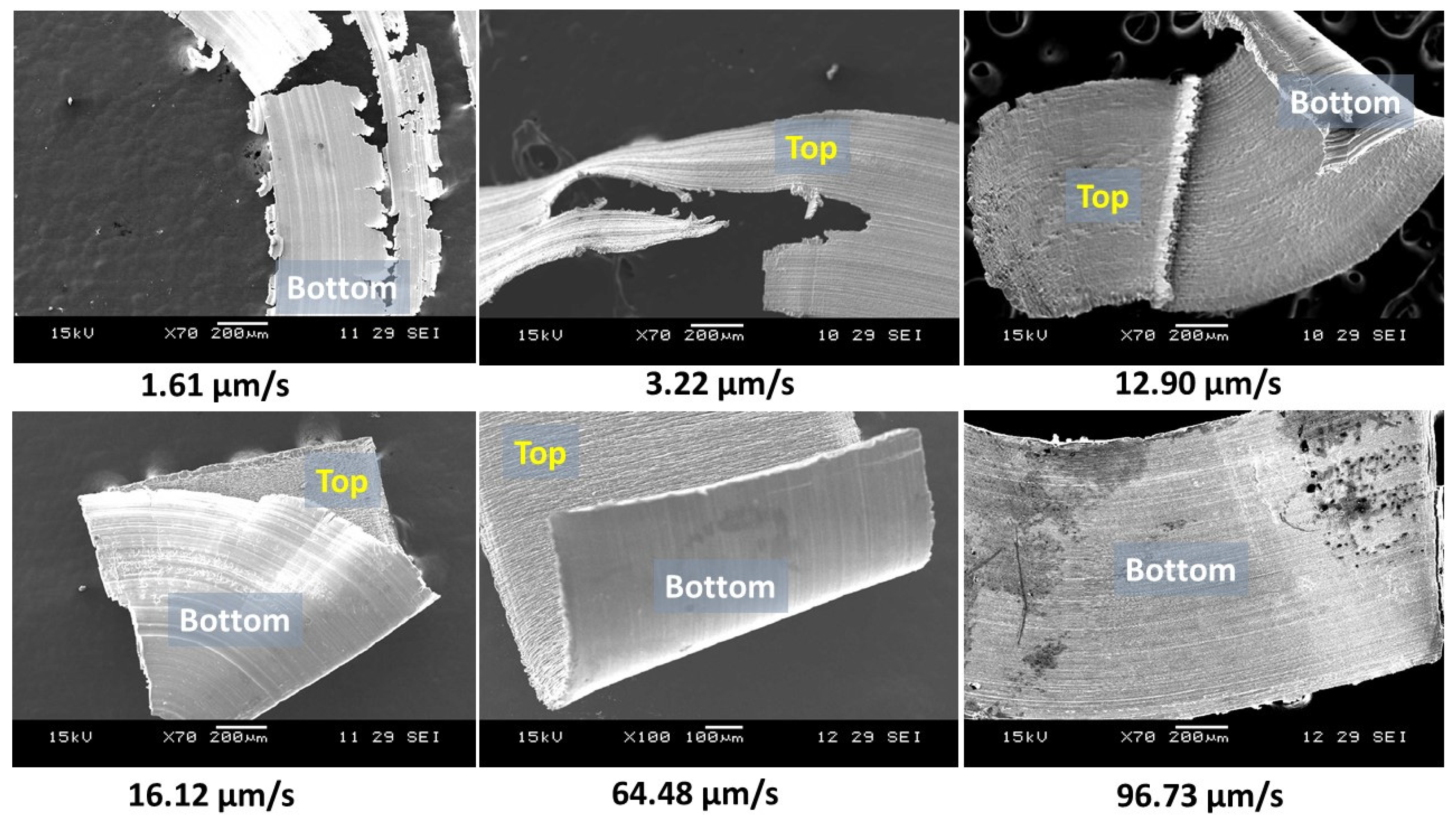
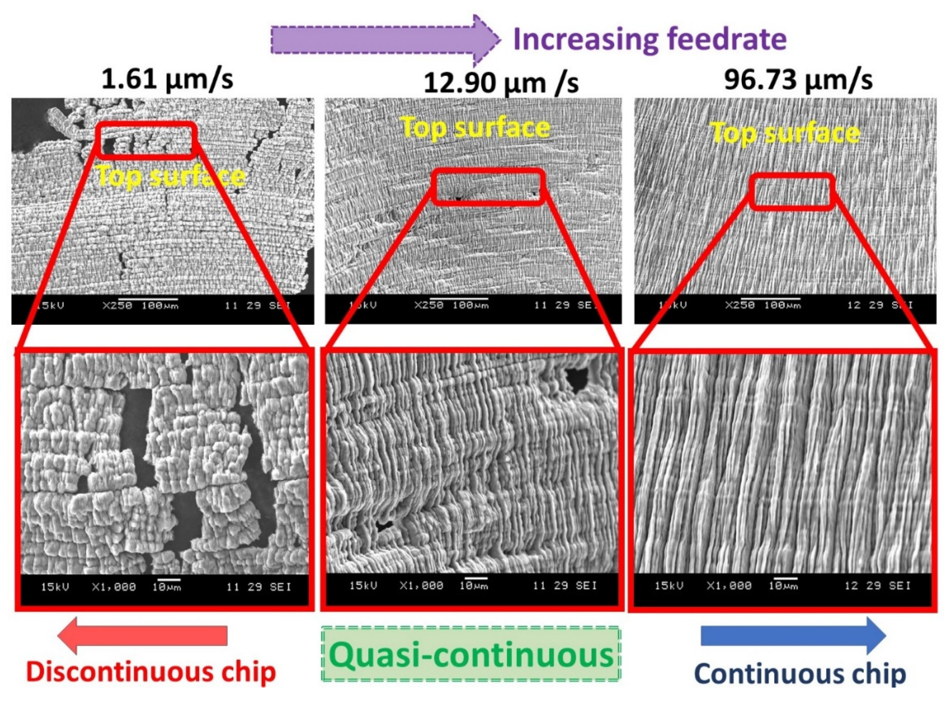
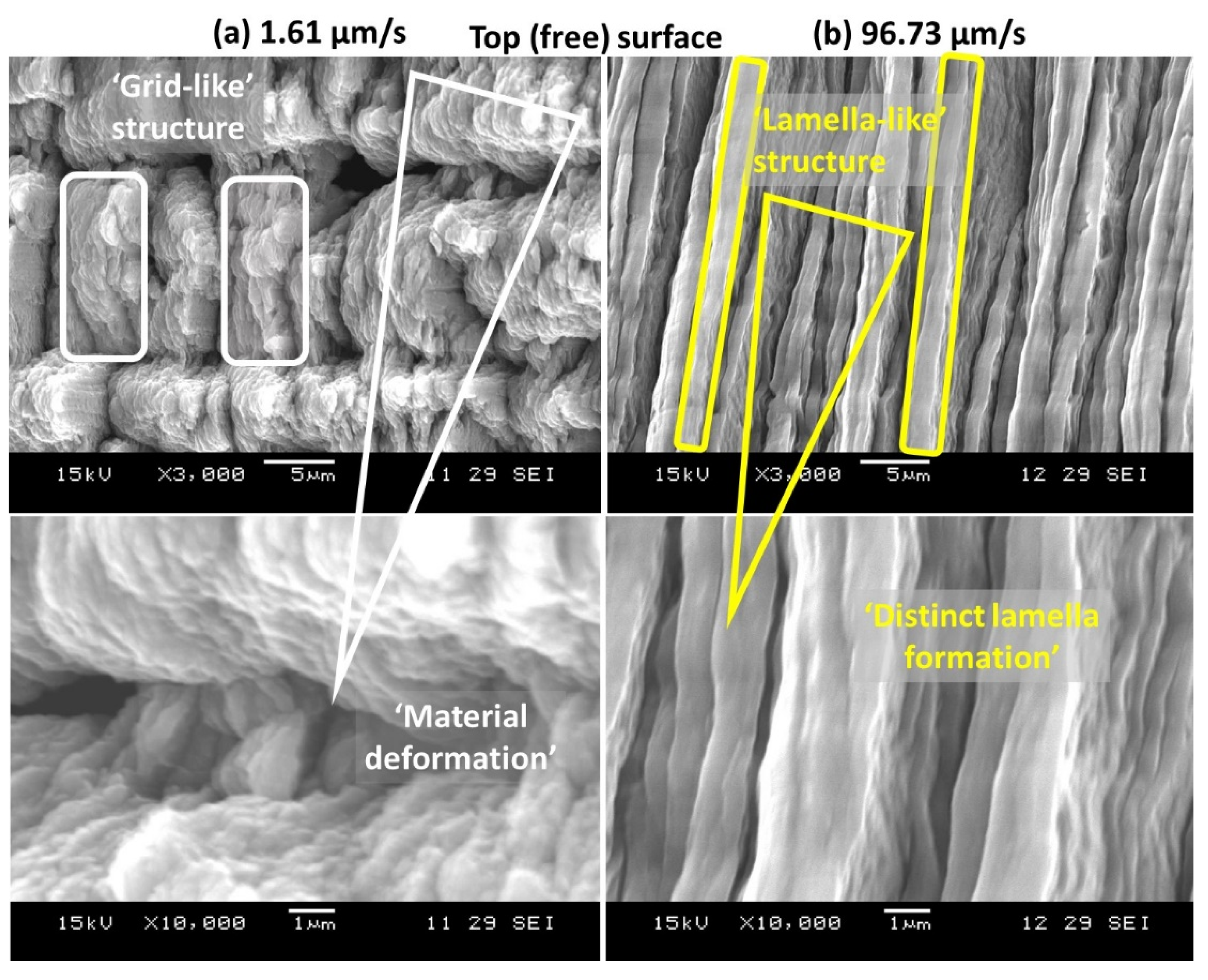
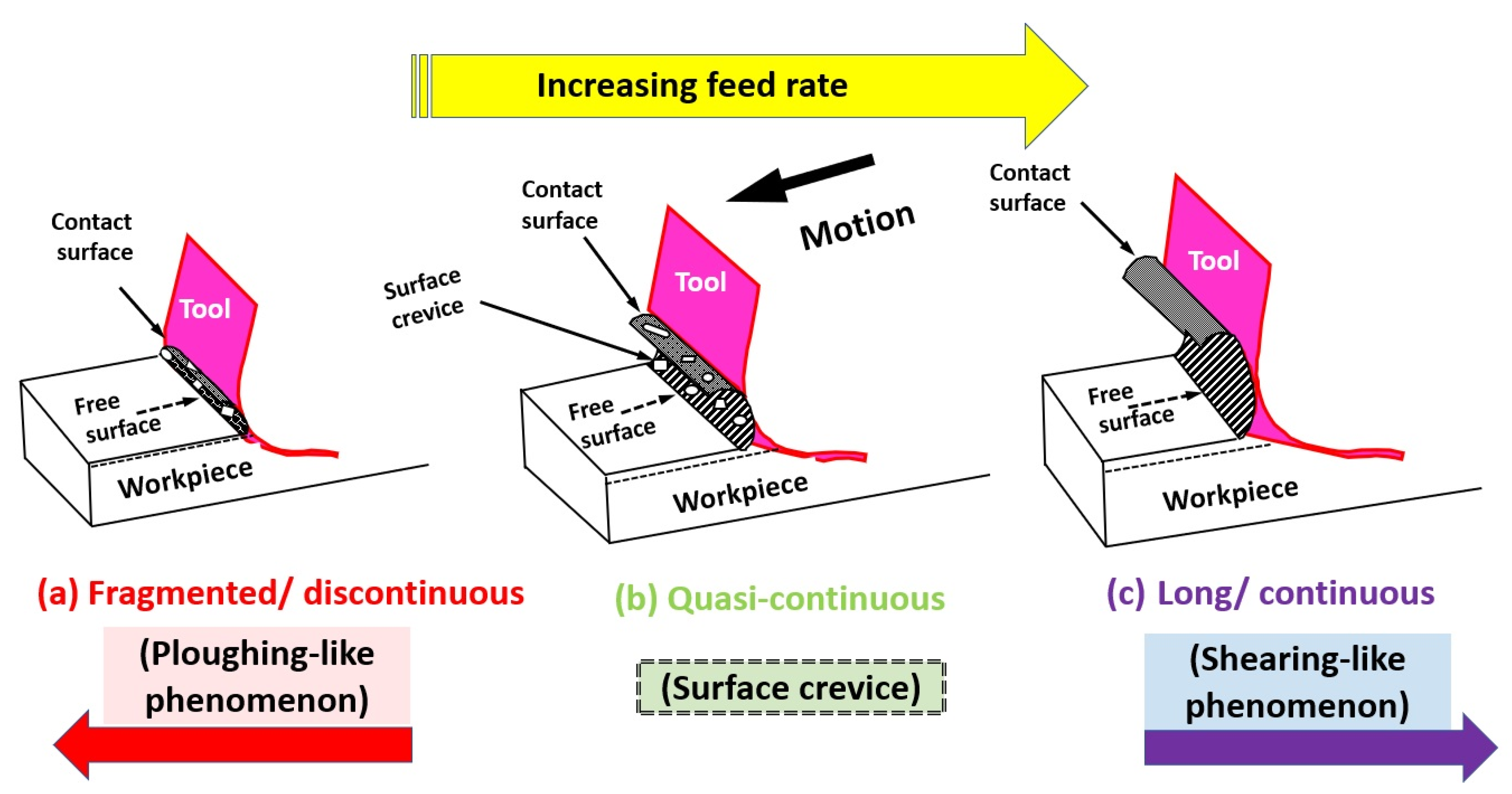
  • In precision micro machining, Al alloy chips exhibited varied characteristics with variation of feed rate (f). At a small feed rate, the materials produced debris-like fragmented chips, while a high feed rate rendered long and continuous chips. Analysis of μ-chips under SEM provided three distinct chip formation mechanics (i.e., discontinuous, quasi-continuous, and continuous).
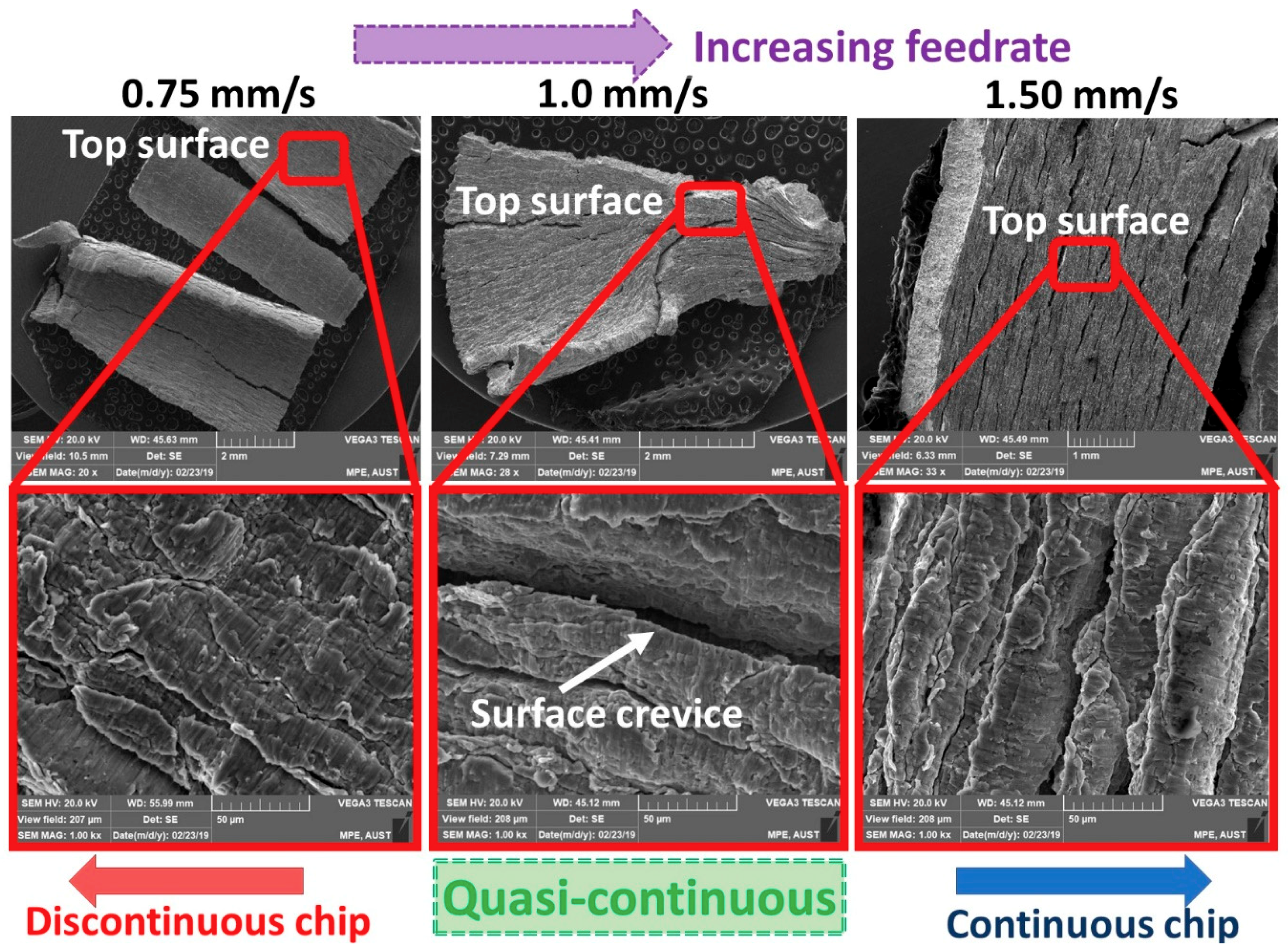
  • In conventional macro machining, with the variation of the feed rate (f), Al alloy chips exhibited varied characteristics too. Similar to the micro machining, at a smaller feed rate, discontinuous chips were produced, while a high feed rate produced mostly long and continuous chips. Only a detailed observation of the chips at higher magnifications showed three distinct chip formation mechanics (i.e., discontinuous, quasi-continuous, and continuous).
  • Micro holes formation in Al alloy microchips were activated by the micro crevice formation due to the onset of a stagnation point phenomenon in the transition regime between the discontinuous and continuous chip formation, which occurred at an intermediate feed rate. A similar phenomenon of crevice-like formations was noticed from Al alloy in macro machining conditions. This is akin to the chip surface tearing of different materials, such as Ti alloy.
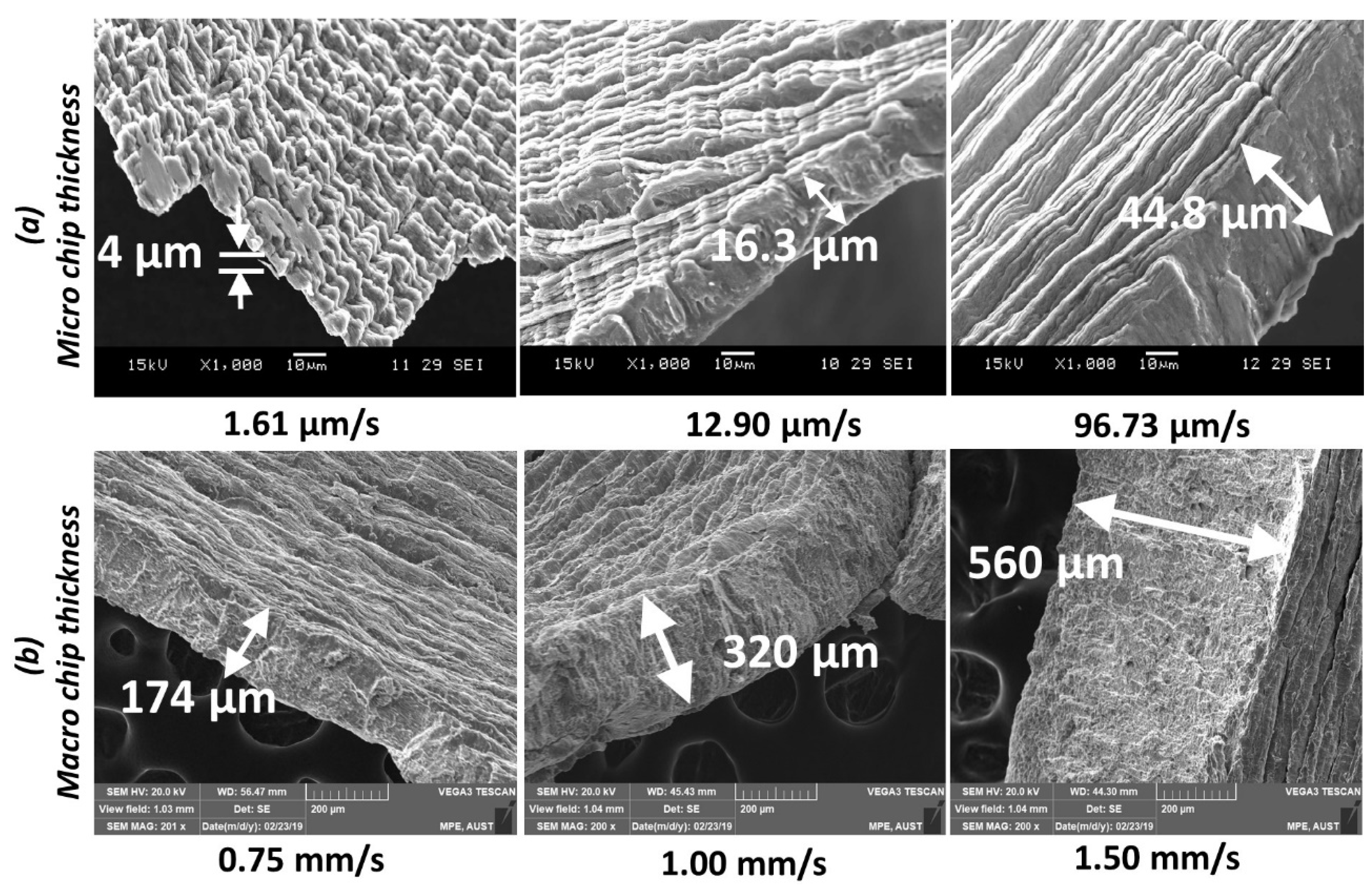
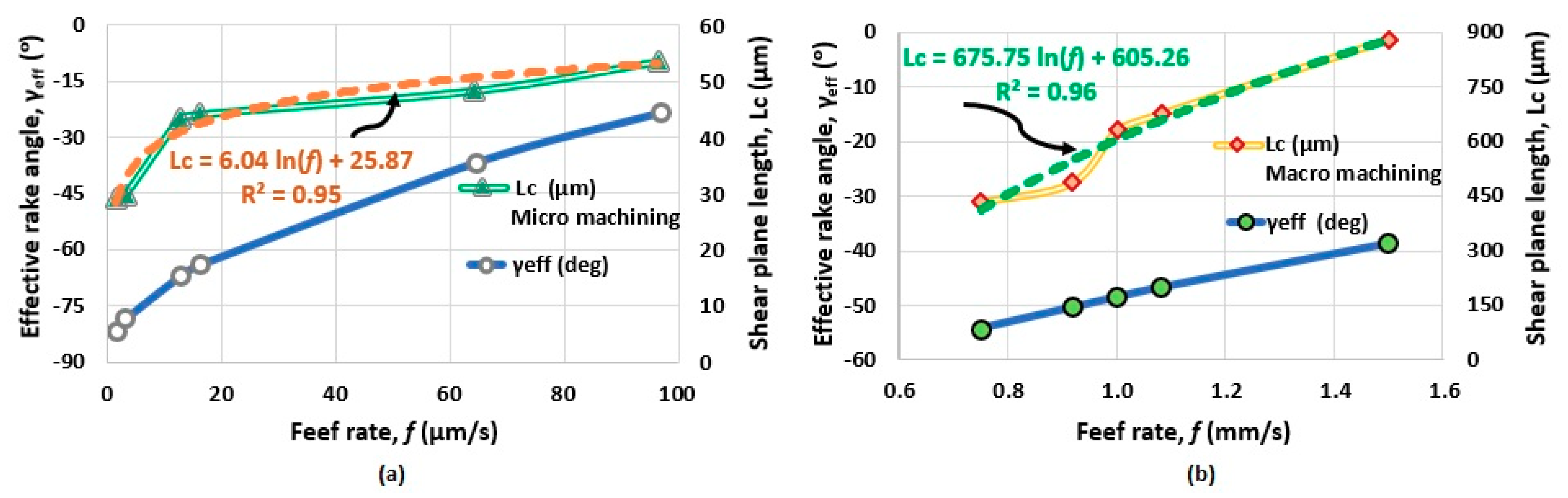
  • A SEM investigation of Al alloy chip morphology revealed the decreasing trend of chip thickness (ho) with the decrease of feed rate due to the decline in UCT (hc) for both micro and macro machining. This resulted in a decrease in the shear plane length (Lc).
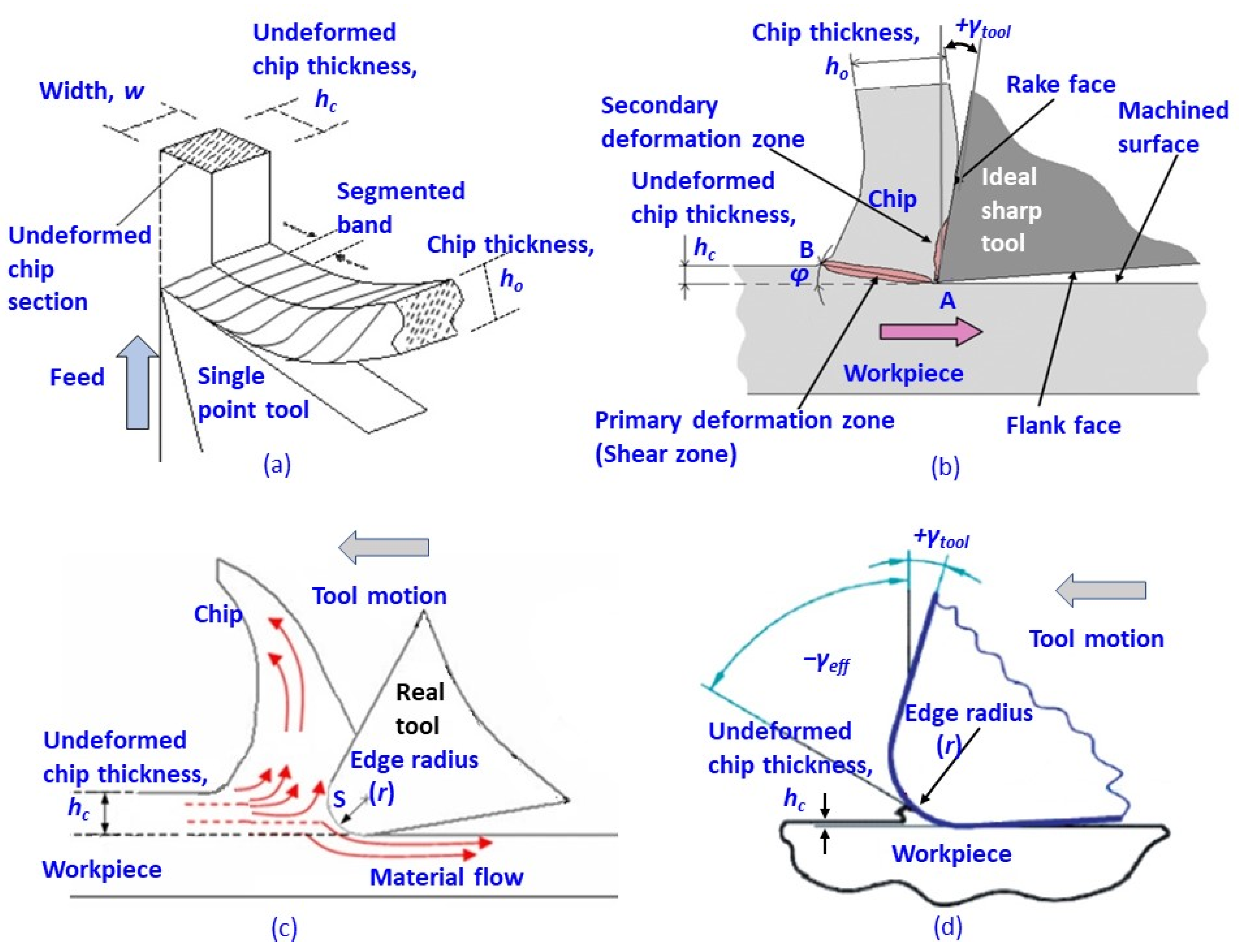
  • A higher material removal rate (MRR) occurs from the combined effect of high relative tool sharpness, RTS (hc/r) resulting from large UCT (hc) at a high feed rate (f). Lower MRR observed at smaller feed rate due to the decreased tool-workpiece interaction is responsible for ploughing-like behavior. This is due to the enormously large negative effective rake angle (−γeff), −81.86° at a feed rate of 1.61 µm/s, and −54.23° at feed rate 0.75 mm/s, during micro and macro machining, respectively.

Author Contributions

Conceptualization, M.A.R., M.M.; formal analysis, M.S.B., M.S.K., S.S. (Shubham Sharma), M.K.G.; funding acquisition, A.A., S.A., M.M.; investigation, M.A.R., M.S.B., S.S. (Shubham Sharma), M.S.K., M.M.M.I.; methodology, M.A.R., S.S. (Shubham Sharma), M.M.; project administration, A.A., S.A., M.M.; resources, M.A.R.; S.A.; software, M.K.G., N.K.; supervision, M.M.; validation, T.-T.N., A.A., S.A., N.K.; visualization, T.-T.N., S.S. (Sourav Sharma); writing—original draft, M.A.R., M.S.B., S.S. (Sourav Sharma), M.K.G., N.K., M.M.; writing—review & editing, A.A., T.-T.N., M.K.G., S.A. and N.K. All authors have read and agreed to the published version of the manuscript.

Funding

Researchers Supporting Project number (RSP-2020/256), King Saud University, Riyadh, Saudi Arabia.

Institutional Review Board Statement

Not applicable.

Informed Consent Statement

Not applicable.

Data Availability Statement

All data is included in the manuscript.

Acknowledgments

Micro machining experiment conducted in the Advanced Manufacturing Laboratory (AML) at Department of Mechanical Engineering, National University of Singapore (NUS), Singapore. Conventional macro machining experiment performed in the Machine Tool Laboratory at the Department of Mechanical Engineering, Ahsanullah University of Science and Technology (AUST), Bangladesh. The authors also extend their appreciation to King Saud University for funding this work through the Researchers Supporting Project number (RSP-2020/256), King Saud University, Riyadh, Saudi Arabia.

Conflicts of Interest

The authors declare no conflict of interest.

References

  1. Rasagopal, P.; Senthilkumar, P.; Nallakumarasamy, G.; Magibalan, S.A. study surface integrity of aluminum hybrid composites during milling operation. J. Mater. Res. Technol. 2020, 9, 4884–4893. [Google Scholar] [CrossRef]
  2. Rahman, M.A.; Rahman, M.; Mia, M.; Asad, A.M.B.A.; Fardin, A. Manufacturing of Al Alloy Microrods by Micro Cutting in a Micromachining Center. Micromachines 2019, 10, 831. [Google Scholar] [CrossRef] [Green Version]
  3. König, W.; Erinski, D. Machining and Machinability of Aluminium Cast Alloys. CIRP Ann. 1983, 32, 535–540. [Google Scholar] [CrossRef]
  4. Kouadri, S.; Necib, K.; Atlati, S.; Haddag, B.; Nouari, M. Quantification of the chip segmentation in metal machining: Application to machining the aeronautical aluminium alloy AA2024-T351 with cemented carbide tools WC-Co. Int. J. Mach. Tools Manuf. 2013, 64, 102–113. [Google Scholar] [CrossRef]
  5. Dwivedi, D.K.; Sharma, A.; Rajan, T.V. Machining of LM13 and LM28 Cast Aluminum Alloys Part-I. J. Mater. Proc. Technol. 2008, 196, 197–204. [Google Scholar] [CrossRef]
  6. Sharma, V.S.; Dhiman, S.; Sehgal, R.; Kumar, S. Assessment and Optimization of Cutting Parameters While Turning AlSI, 52100 Steel. Int. J. Precis. Eng. Manuf. 2008, 9, 54–62. [Google Scholar]
  7. Wang, G.; Zhao, Y.; Hao, Y. Friction stir welding of high-strength aerospace aluminum alloy and application in rocket tank manufacturing. J. Mater. Sci. Technol. 2018, 34, 73–91. [Google Scholar] [CrossRef]
  8. Heinz, A.; Haszler, A.; Keidel, C.; Moldenhauer, S.; Benedictus, R.; Miller, W.S. Recent development in aluminium alloys for aerospace applications. Mater. Sci. Eng. A 2000, 280, 102–107. [Google Scholar] [CrossRef]
  9. Demir, H.; Gündüz, S. The effects of aging on machinability of 6061 aluminium alloy. J. Mater. Des. 2009, 30, 1480–1483. [Google Scholar] [CrossRef]
  10. Polini, R.; Casadeib, F.; D’Antonio, P.; Traversa, E. Dry turning of alumina/aluminum composites with CVD diamond coated cocemented tungsten carbide tolls. Surf. Coat. Technol. 2003, 166, 127–143. [Google Scholar] [CrossRef] [Green Version]
  11. Anand, V.K.; Aherwar, A.; Mia, M.; Elfakir, O.; Liliang, W. Influence of silicon carbide and porcelain on tribological performance of Al6061 based hybrid composites. Tribol. Int. 2020, 151, 106514. [Google Scholar] [CrossRef]
  12. Sharma, P.; Khanduja, D.; Sharma, S. Dry sliding wear investigation of Al6082/Gr metal matrix composites by response surface methodology. J. Mater. Res. Technol. 2016, 5, 29–36. [Google Scholar] [CrossRef] [Green Version]
  13. Tang, Z.T.; Liu, Z.Q.; Pan, Y.Z.; Wan, Y.; Ai, X. The influence of tool flank wear on residual stresses induced by milling aluminum alloy. J. Mater. Process. Technol. 2009, 209, 4502–4508. [Google Scholar] [CrossRef]
  14. Kannan, S.; Kishawy, H.A. Tribological aspects of machining aluminium metal matrix composites. J. Mater. Process. Technol. 2008, 198, 399–406. [Google Scholar] [CrossRef]
  15. Gupta, M.K.; Mia, M.; Singh, G.; Pimenov, D.Y.; Sarikaya, M.; Sharma, V.S. Hybrid cooling-lubrication strategies to improve surface topography and tool wear in sustainable turning of Al 7075-T6 alloy. Int. J. Adv. Manuf. Technol. 2019, 101, 55–69. [Google Scholar] [CrossRef]
  16. Huda, Z.; Taib, N.I.; Zaharinie, T. Characterization of 2024-T3: An aerospace aluminum alloy. Mater. Chem. Phys. 2009, 113, 515–517. [Google Scholar] [CrossRef]
  17. Gutowski, T.G.; Sahil, S.; Allwood, J.; Ashby, M.; Worrell, E. The Energy Required to Produce Materials: Constraint on Energy Intensity-improvements Parameters of Demand. Philos. Trans. A 2013. [Google Scholar] [CrossRef]
  18. Santos, M.C.; Machado, A.R.; Sales, W.F. Machining of aluminum alloys: A review. Int. J. Adv. Manuf. Technol. 2016, 86, 3067–3080. [Google Scholar] [CrossRef]
  19. Rahman, M.A.; Rahman, M.; Kumar, A.S.; Lim, H.S. CNC microturning: An application to miniaturization. Int. J. Mach. Tools Manuf. 2005, 45, 631–639. [Google Scholar] [CrossRef]
  20. Byrne, G.; Dornfeld, D.; Denkena, B. Advancing Cutting Technology. CIRP Ann. 2003, 52, 483–507. [Google Scholar] [CrossRef] [Green Version]
  21. Kumar, S.P.L.; Jerald, J.; Kumanan, S.; Prabakaran, R. A Review on Current Research Aspects in Tool-Based Micromachining Processes. Mater. Manuf. Process. 2014, 29, 1291–1337. [Google Scholar] [CrossRef]
  22. Zhang, S.; Zhou, Y.; Zhang, H.; Xiong, Z.; To, S. Advances in ultra-precision machining of micro-structured functional surfaces and their typical applications. Int. J. Mach. Tools Manuf. 2019, 142, 16–41. [Google Scholar] [CrossRef]
  23. Elisa, V.; Ciro, A.R.; Alex, E.Z.; Joaquim, C. An experimental analysis of process parameters to manufacture metallic micro-channels by micro-milling. Int. J. Adv. Manuf. Technol. 2010, 51, 945–955. [Google Scholar] [CrossRef]
  24. Zariatin, D.L.; Kiswanto, G.; Ko, T.J. Investigation of the micro-milling process of thin-wall features of aluminum alloy 1100. Int. J. Adv. Manuf. Technol. 2017, 93, 2625–2637. [Google Scholar] [CrossRef]
  25. Zheng, L.; Wang, C.; Yang, L.; Song, Y.; Fu, L. Characteristics of chip formation in the micro-drilling of multi-material sheets. Int. J. Mach. Tools Manuf. 2012, 52, 40–49. [Google Scholar] [CrossRef]
  26. Wang, S.; Xia, S.; Wang, H.; Yin, Z.; Sun, Z. Prediction of surface roughness in diamond turning of Al6061 with precipitation effect. J. Manuf. Process. 2020, 60, 292–298. [Google Scholar] [CrossRef]
  27. Rahman, M.A.; Woon, K.S.; Rahman, M. Miniaturization by precision micro cutting. J. Prod. Syst. Manuf. Sci. 2020, 1, 1–4. Available online: http://www.imperialopen.com/index.php/JPSMS/article/view/48 (accessed on 26 October 2020).
  28. Songmene, V.; Khettabi, R.; Zaghbani, I.; Kouam, J.; Djebara, A. Machining and Machinability of Aluminum Alloys. In Aluminium Alloys, Theory and Applications; Kvackaj, T., Ed.; IntechOpen: London, UK, 2011; pp. 377–385. [Google Scholar] [CrossRef] [Green Version]
  29. Haider, J.; Hashmi, M.S.J. Health and Environmental Impacts in Metal Machining Processes. In Comprehensive Materials Processing; Hashmi, S., Batalha, G.F., Tyne, C.J.V., Yilbas, B., Eds.; Elsevier: Oxford, UK, 2014; Volume 1, pp. 7–33. [Google Scholar] [CrossRef]
  30. Woon, K.S.; Rahman, M.; Fang, F.Z.; Neo, K.S.; Liu, K. Investigations of tool edge radius effect in micromachining: A FEM simulation approach. J. Mater. Process. Technol. 2008, 195, 204–211. [Google Scholar] [CrossRef]
  31. Rubenstein, C.; Lau, W.S.; Venuvinod, P.K. Flow of workpiece material in the vicinity of the cutting edge. Int. J. Mach. Tool Des. Res. 1985, 25, 91–97. [Google Scholar] [CrossRef]
  32. Fang, F.; Xu, F.; Lai, M. Size effect in material removal by cutting at nano scale. Int. J. Adv. Manuf. Technol. 2015, 80, 591–598. [Google Scholar] [CrossRef]
  33. Wang, J.S.; Gong, Y.D.; Abba, G.; Chen, K.; Shi, J.S.; Cai, G.Q. Surface generation analysis in micro end-milling considering the influences of grain. Microsyst. Technol. 2008, 14, 937–942. [Google Scholar] [CrossRef] [Green Version]
  34. Rahman, M.A.; Amrun, M.R.; Rahman, M.; Kumar, A.S. Variation of surface generation mechanisms in ultra-precision machining due to relative tool sharpness (RTS) and material properties. Int. J. Mach. Tools Manuf. 2017, 115, 15–28. [Google Scholar] [CrossRef]
  35. Liu, X.; DeVor, R.; Kapoor, S.G.; Ehmann, K. The mechanics of machining at the microscale: Assessment of the current state of the science. J. Manuf. Sci. Eng. 2004, 126, 666–678. [Google Scholar] [CrossRef]
  36. Zhang, X.Q.; Woon, K.S.; Rahman, M. Diamond Turning. In Comprehensive Materials Processing; Hashmi, S., Batalha, G.F., Tyne, C.J.V., Yilbas, B., Eds.; Elsevier: Oxford, UK, 2014; Volume 1, pp. 201–220. [Google Scholar] [CrossRef]
  37. Lucca, D.A.; Seo, Y.W. Effect of Tool Edge Geometry on Energy Dissipation in Ultraprecision Machining. Ann. CIRP 1993, 42, 83–86. [Google Scholar] [CrossRef]
  38. Shi, Z.; Li, Y.; Liu, Z.; Qiao, Y. Determination of minimum uncut chip thickness during micro-end milling Inconel 718 with acoustic emission signals and FEM simulation. Int. J. Adv. Manuf. Technol. 2018, 98, 37–45. [Google Scholar] [CrossRef]
  39. Mian, A.J.; Driver, N.; Mativenga, P.T. Chip formation in microscale milling and correlation with acoustic emission signal. Int. J. Adv. Manuf. Technol. 2011, 56, 63–78. [Google Scholar] [CrossRef]
  40. Abeni, A.; Loda, D.; Özel, T.; Attanasio, A. Analytical force modelling for micro milling additively fabricated Inconel 625. Prod. Eng. 2020, 14, 613–627. [Google Scholar] [CrossRef]
  41. Abeni, A.; Ginestra, P.S.; Attanasio, A. Micro-milling of Selective Laser Melted Stainless Steel. In Selected Topics in Manufacturing; Lecture Notes in Mechanical Engineering; Ceretti, E., Tolio, T., Eds.; Springer: Cham, Switzerland, 2021; Volume 1, pp. 1–12. [Google Scholar] [CrossRef]
  42. Rahman, M.A.; Rahman, M.; Kumar, A.S. Material perspective on the evolution of micro- and nano-scale cutting of metal alloys. J. Micromanufacturing 2018, 1, 97–114. [Google Scholar] [CrossRef]
  43. Jawahir, I.; Van Luttervelt, C. Recent developments in chip control research and applications. CIRP Ann. 1993, 42, 659–693. [Google Scholar] [CrossRef]
  44. Ng, C.K.; Melkote, S.N.; Rahman, M.; Kumar, A.S. Experimental study of micro- and nano-scale cutting of aluminum 7075-T6. Int. J. Mach. Tools Manuf. 2006, 46, 929–936. [Google Scholar] [CrossRef]
  45. Haque, R.; Imran, G.M.S.; Zaman, A.; Rahman, M.A. Influence of cutting parameters causing variation of surface roughness and chip characteristics of Mg AZ31B Alloy. J. Prod. Syst. Manuf. Sci. 2020, 1, 42–56. [Google Scholar]
  46. Korkmaz, M.E.; Yaşar, N. FEM modelling of turning of AA6061-T6: Investigation of chip morphology, chip thickness and shear angle. J. Prod. Syst. Manuf. Sci. 2020, 2, 50–58. [Google Scholar]
  47. Rahman, M.A.; Woon, K.S.; Venkatesh, V.C.; Rahman, M. Modelling of the combined microstructural and cutting edge effects in ultraprecision machining. CIRP Ann. 2018, 67, 129–132. [Google Scholar] [CrossRef]
  48. Rahman, M.A.; Rahman, M.; Kumar, A.S. Modelling of flow stress by correlating the material grain size and chip thickness in ultra-precision machining. Int. J. Mach. Tools Manuf. 2017, 123, 57–75. [Google Scholar] [CrossRef]
  49. Doman, D.A.; Warkentin, A.; Bauer, R. Finite element modeling approaches in grinding. Int. J. Mach. Tools Manuf. 2009, 49, 109–116. [Google Scholar] [CrossRef]
  50. Bridgman, P.; Šimon, I. Effects of very high pressures on glass. J. Appl. Phys. 1953, 24, 405–413. [Google Scholar] [CrossRef]
  51. Wang, J.; Zhang, X.; Fang, F.; Chen, R. A numerical study on the material removal and phase transformation in the nanometric cutting of silicon. Appl. Surf. Sci. 2018, 455, 608–615. [Google Scholar] [CrossRef]
  52. Lee, W.B.; Cheung, C.F.; To, S. A microplasticity analysis of micro-cutting force variation in ultra-precision diamond turning. J. Manuf. Sci. Eng. 2002, 124, 170–177. [Google Scholar] [CrossRef] [Green Version]
  53. Rahman, M.A.; Rahman, M.; Mia, M.; Gupta, M.K.; Sen, B.; Ahmed, A. Investigation of the specific cutting energy and its effect in shearing dominant precision micro cutting. J. Mater. Process. Technol. 2020, 283, 116688. [Google Scholar] [CrossRef]
  54. Yuan, Z.J.; Lee, W.B.; Yao, Y.X.; Zhou, M. Effect of crystallographic orientation on cutting forces and surface quality in diamond cutting of single crystal. CIRP Ann. Manuf. Technol. 1994, 43, 39–42. [Google Scholar] [CrossRef]
  55. Yan, J.; Okuuchi, T. Chip morphology and surface integrity in ultraprecision cutting of yttria-stabilized tetragonal zirconia polycrystal. CIRP Ann. 2019, 68, 53–56. [Google Scholar] [CrossRef]
  56. Chaudhari, A.; Soh, Z.U.; Wang, H.; Kumar, A.S. Rehbinder effect in ultraprecision machining of ductile materials. Int. J. Mach. Tools Manuf. 2018, 133, 47–60. [Google Scholar] [CrossRef]
  57. Ramalingam, S.; Black, J.T. An electron microscopy study of chip formation. Metall. Mater. Trans. B 1973, 4, 1103–1112. [Google Scholar] [CrossRef]
  58. Djebara, A.; Zedan, Y.; Kouam, J.; Songmene, V. The Effect of the Heat Treatment on the Dust Emission during Machining of an Al-7Si-Mg Cast Alloys. J. Mater. Eng. Perform. 2013, 22, 3840–3853. [Google Scholar] [CrossRef] [Green Version]
  59. Rai, R.N.; Datta, G.L.; Chakraborty, M.; Chattopadhyay, A.B. A study on the machinability behaviour of Al–TiC composite prepared by in situ technique. Mater. Sci. Eng. A 2006, 428, 34–40. [Google Scholar] [CrossRef]
  60. Rahman, M.A.; Amrun, M.R.; Rahman, M.; Kumar, A.S. Effect of cutting edge radius on ‘burnishing-like’ mechanism in micromachining. Int. J. Precis. Technol. 2018, 8, 85–103. [Google Scholar] [CrossRef]
  61. Childs, T.H.C.; Dornfeld, D.; Lee, D.E.; Min, S.; Sekiya, K.; Tezuka, R.; Yamane, Y. The influence of cutting edge sharpness on surface finish in facing with round nosed cutting tools. CIRP J. Manuf. Sci. Technol. 2008, 1, 70–75. [Google Scholar] [CrossRef] [Green Version]
  62. Lucca, D.A. Tribological Aspects of Ultraprecision and Nanometric Cutting. In Encyclopedia of Tribology; Wang, Q.J., Chung, Y.W., Eds.; Springer: Boston, MA, USA, 2013; pp. 3767–3771. [Google Scholar]
  63. Shinge, A.R.; Dabade, U.A. The Effect of Process Parameters on Material Removal Rate and Dimensional Variation of Channel Width in Micro-milling of Aluminium Alloy 6063 T6. Procedia Manuf. 2018, 20, 168–173. [Google Scholar] [CrossRef]
  64. Khanna, N.; Agrawal, C.; Dogra, M.; Pruncu, C.I. Evaluation of tool wear, energy consumption, and surface roughness during turning of inconel 718 using sustainable machining technique. J. Mater. Res. Technol. 2020, 9, 5794–5804. [Google Scholar] [CrossRef]
  65. Lai, X.; Li, H.; Li, C.; Lin, Z.; Ni, J. Modelling and analysis of micro scale milling considering size effect, micro cutter edge radius and minimum chip thickness. Int. J. Mach. Tool Manuf. 2008, 48, 1–14. [Google Scholar] [CrossRef]
  66. Abouridouane, M.; Klocke, F.; Lung, D.; Adams, O. Size Effects in Micro Drilling Ferritic-Pearlitic Carbon Steels. Procedia CIRP 2012, 3, 91–96. [Google Scholar] [CrossRef] [Green Version]
  67. Boothroyd, G.; Knight, W.A. Fundamentals of Machining and Machine Tools, 2nd ed.; Marcel Dekker: New York, NY, USA, 1989; pp. 73–99. [Google Scholar]
  68. Zhang, X.; Arif, M.; Liu, K.; Kumar, A.S.; Rahman, M. A model to predict the critical undeformed chip thickness in vibration-assisted machining of brittle materials. Int. J. Mach. Tools Manuf. 2013, 69, 57–66. [Google Scholar] [CrossRef]
  69. Woon, K.S. Modeling of the Tool Edge Radius Effect. Ph.D. Thesis, NUS, Singapore, 2009. [Google Scholar]
  70. Yuan, Z.J.; Zhou, M.; Dong, S. Effect of Diamond Tool Sharpness on Minimum Cutting Thickness and Cutting Surface Integrity in Ultraprecision Machining. J. Mater. Process. Technol. 1996, 62, 327–330. [Google Scholar] [CrossRef]
  71. Smith, G.T. Cutting Tool Technology: Industrial Handbook; Springer: London, UK, 2008; pp. 291–297. [Google Scholar]
  72. Archenti, A.; Nicolescu, M. Accuracy analysis of machine tools using Elastically Linked Systems. CIRP Ann. 2013, 62, 503–506. [Google Scholar] [CrossRef]
  73. Yip, W.; To, S. Ductile and brittle transition behavior of titanium alloys in ultra-precision machining. Sci. Rep. 2018, 8, 3934. [Google Scholar] [CrossRef] [PubMed] [Green Version]
  74. Heidari, M.; Yan, J. Nanometer-scale chip formation and surface integrity of pure titanium in diamond turning. Int. J. Adv. Manuf. Technol. 2018, 95, 479–492. [Google Scholar] [CrossRef]
Figure 1. Schematic of (a) 3D view of orthogonal cutting with single-point cutting tool [28] (b) 2D view of macro machining model [29] (c) 2D view of micromachining model [30] (d) 2D view of ploughing in micromachining [33]. Copyright Permission obtained.
Metals 11 00159 g001
Figure 2. Al alloy workpiece and cutting tool insert used in micromachining in the Toshiba ULG-100C(H3) ultra-precision lathe (a,e,g) and macro machining in CS6266B conventional lathe (b,f,h) with microstructure (c) and cutting scheme (d).
Metals 11 00159 g002
Figure 3. Micromachined chips of Al alloy produced 100 m/min (636 rpm) with various feed rates.
Metals 11 00159 g003
Figure 4. Varying microchip morphology observed through scanning electron microscope (SEM) image analysis.
Metals 11 00159 g004
Figure 5. Free (top) surface of the Al alloy microchips noticed in SEM image analysis.
Metals 11 00159 g005
Figure 6. Distinct Al alloy microchip morphology in (a) low feed rate (1.61 µm/s) and (b) high feed rate (96.73 µm/s).
Metals 11 00159 g006
Figure 7. Effect of feed rate on Al alloy chip formed in conventional macro machining.
Metals 11 00159 g007
Figure 8. Effect of feed rate on macro chip formation of Al alloy.
Metals 11 00159 g008
Figure 9. SEM image analysis of the top (free) surface of Al alloy macro chips.
Metals 11 00159 g009
Figure 10. Combined effect of relative tool sharpness (RTS), feed rate and material removal rate (MRR) in (a) micro and (b) macro machining.
Metals 11 00159 g010
Figure 11. Surface crevice at feed rate 12.90 μm/s observed in ×5000 magnification SEM image of free and contact surface of Al alloy the microchip.
Metals 11 00159 g011
Figure 12. Surface crevice at feed rate 1.00 mm/s observed about ×5000 magnification SEM image of free and contact surface of Al alloy the macro chip.
Metals 11 00159 g012
Figure 13. Measurement of deformed chip thickness (ho) of Al alloy with varying feed rate (f) for (a) micro machining (b) macro machining.
Metals 11 00159 g013
Figure 14. Variation of effective rake angle (γeff) and length of the shear plane (Lc) for (a) micro and (b) macro machining.
Metals 11 00159 g014
Figure 15. Morphology of contact surface of Al alloy chip produced in (a) micro machining (b) macro machining.
Metals 11 00159 g015
Figure 16. Schematic of FRR (feed rate response) on the mechanics on chip formation.
Metals 11 00159 g016
Table 1. Cutting Tool, Machine Tool, Machining Parameters.
ProcessMicromachiningMacro Machining
Cutting Tool InsertSumitomo CBN
(2NC-CCGW09T308)
(−25° rake angle)
P type carbide
(VCMT160408-SM)
(7° rake angle)
Machine ToolUltra-precision lathe,
Toshiba ULG-100C(H3)
Horizontal engine lathe, Model CS6266B
Cutting speed 100 m/min70.6 m/min
Spindle speed636 rpm500 rpm
Feed rate1.61–96.72 µm/s0.75–1.50 mm/s
Feed ratio, FR (Feed/Lowest feed)1, 2, 8, 10, 40, 601, 1.22, 1.33, 1.44, 1.55, 2
Publisher’s Note: MDPI stays neutral with regard to jurisdictional claims in published maps and institutional affiliations.

