Article

Surface Residual Stress Analysis in GMAW and LBW of the Dissimilar TRIP-DP Steels Joint: An Experimental Approach

by
Víctor H. Baltazar-Hernández
1,*,
Enrique A. López-Baltazar
1,
Francisco Alvarado-Hernández
1,
Salvador Gómez-Jiménez
1,
José Jorge Ruiz-Mondragón
2,
Elliot Biro
3 and
Norman Zhou
3
1
Materials Science and Engineering Program, Unidad Académica de Ingeniería, Universidad Autónoma de Zacatecas, Zacatecas 98000, Zacatecas, Mexico
2
Corporación Mexicana de Investigación en Materiales SA de CV, Saltillo 25290, Coahuila, Mexico
3
Centre for Advanced Materials Joining, University of Waterloo, Waterloo, ON N2L 3G1, Canada
*
Author to whom correspondence should be addressed.
Submission received: 21 April 2022 / Revised: 14 May 2022 / Accepted: 18 May 2022 / Published: 23 May 2022
(This article belongs to the Special Issue Welding and Joining of Advanced High-Strength Steels)

Abstract

:
A transformation-induced plasticity (TRIP) steel and a dual-phase (DP) steel were paired together by employing gas metal arc welding (GMAW) and laser beam welding (LBW) processes. The post-weld microstructure, the hardness profile, and the uniaxial tensile behavior of the welded steels have been analyzed in detail. The experimental surface residual stress distribution across the weldment was measured through the X-ray diffraction sin2Ψ technique. The results indicate that although a harder microstructure composed of predominant martensite was observed along the weldment, the uniaxial tensile behavior resulted in better elongation properties and a higher UTS in the LBW specimen as compared to the GMAW specimen. The resultant residual stress distribution in the heat-affected zone (HAZ) had an increase to a maximum value, followed by a steady decrease up to the base metal following the trend: upper-critical UC-HAZ (maximum) → inter-critical IC-HAZ (moderated) → subcritical SC-HAZ (lowered), which was particularly more evident on the GMAW specimen. Overall, the resultant residual stresses along the weldment were lower on the LBW specimen (172 MPa maximum) which clearly contrasts to the GMAW specimen (421 MPa maximum). Finally, the tensile residual stresses in both the GMAW or LBW did not influence the overall tensile properties of the weldments.

1. Introduction

A reduction in gas consumption and proper emission control are key advantages in the automotive industry [1,2], particularly when employing advanced high-strength steels (AHSSs) in the fabrication of contemporary automobiles. Nowadays, AHSSs play an essential role in the autobody assembly due to their excellent combination of strength and ductility. Among the first generation of AHSSs, the transformation-induced plasticity (TRIP) steel and the dual-phase (DP) steel possess a suitable combination and varied fractions of martensite, pearlite, bainite, ferrite, and retained austenite microstructures that distinctly contribute to their outstanding mechanical behavior [3].
It is commonly known that a widely employed welding process in autobody construction is resistance spot welding (RSW) [4,5]; however, other welding processes are available for specific purposes when joining AHSSs, for example, gas metal arc welding (GMAW) can be properly applied to join components demanding high-load-bearing capacity [5,6,7] and/or enhanced fatigue strength [8,9,10,11,12], such as the chassis, suspension parts, reinforcement bars, pillars, etc. [6,13]. The advantages of the GMAW of AHSSs are realized when joining dissimilar steel grades or different steel sheet thickness [14]; indeed, the filler metal can be properly selected in order to further control the fusion zone (FZ) chemistry and the post-welding microstructure and, therefore, the overall mechanical performance of the weldment [15,16]. On the other hand, if ductility and formability behavior are principal requirements, i.e., tailored welded blanks of AHSSs, then laser beam welding (LBW) offers reasonable advantages [17,18]. Particularly, the lower heat input of fiber laser welding promotes a narrower FZ and heat-affected zone (HAZ); hence, the microstructure gradient extension along the weldment is clearly reduced, thus resulting in an attractive combination of strength and elongation [19,20,21,22]. In terms of the phase/microstructure development, the rapid cooling rates encountered in LBW consistently generate a hard FZ due to the formation of martensite in DP steel [23]. The softening in the subcritical HAZ (SC-HAZ) due to the tempering of martensite in laser-welded DP steel is almost inexistent, thus contrasting with the distinctly measurable softening in the arc-welded specimens [24]. By comparing the mechanical behavior between arc- and laser-welded AHSSs, it has been demonstrated that the uniaxial tensile strength and the uniform elongation in fiber laser welds are generally higher than arc-welded specimens [25]. Furthermore, the formability behavior clearly depends on the weld hardness, the weld width, and the geometry of the specimen; in spite of that, it has been shown that the maximum formability (a limiting dome-height test) in a Si-TRIP steel is obtained upon fiber-laser-welded specimens [26].
The analysis of the residual stress (RS) distribution is quite important for the mechanical behavior of weldments because it could be feasible to understand and/or predict the possible failure when subjected to tension, fatigue, and/or formability. For instance, experimental RS measurements across a weldment of AHSSs have been investigated in resistance spot welds (RSW) [27]. The experimental RS profiles obtained alongside the weldment in an RSW-TWIP steel indicated a strong dependence on the welding parameters, and the highest RS values were located at the edge of the electrode-to-sheet contact area [28]. The effect of paint baking was evaluated in both resistance spot-welded DP980 and HF980 steels; a significant reduction in residual stress was found in the DP980 steel following the paint-baking procedure, thus clearly improving the overall cross-tension strength [29]. A post-weld cold-working (PWCW) procedure was applied to a dissimilar stack up of resistance spot-welded HC550/980DP steels; the PWCW induced compressive residual stress in both the fusion zone and HAZ, thus suppressing the nucleation and propagation of cracking and therefore improving the fatigue strength of the weldment [30].
It is worth mentioning that the experimental surface residual stress analysis through X-ray diffraction of arc- or laser-welded AHSSs is limited. A low transformation temperature welding (LTTW) consumable was utilized to arc weld DP980 steel plates; X-ray neutron diffraction indicated a reduction in RS in both the fusion zone and heat-affected zone, as compared to the ER70S-3 filler-metal-welded specimen [31]. Two overlapped DP600 steel sheets of 1.25 mm gauge were joined by Nd:YAG laser welding; the lower values of the experimental residual stresses were found in the BM followed by the HAZ and FZ (peak) promoted by the high thermal gradient that decreases in a transverse direction with respect to the weld path [32]. The higher residual stresses located in the HAZ of an arc-welded TS590 high-strength steel as compared to arc-welded TS270 steel were attributed to the higher yield strength in the former steel [33]. Two real automotive components, namely the lateral link and eye bar, composed of SAE1010 and HSLA steels, respectively, were gas metal arc welded and further heat-treated at 343 °C for 2 h in order to relieve the state of residual stresses; interestingly, the fatigue strength was diminished because the post-welding compressive stresses at the toe returned to zero after the treatment, thus negatively affecting the fatigue performance of the weldment [34]. A 5 mm thick high-strength (up to 550 MPa) steel plate was butt-joined by a hybrid fiber laser/GMAW system; the maximum RS decreased when increasing the welding speed, whereas increasing the wire feed rate slightly increased the RS [35]. A 6.3 mm in thickness and hot-rolled TWIP-Ti steel was GTAW without filler metal; it was inferred that the high RS values (i.e., 586 MPa) measured at the FZ-HAZ interface was not accurate due to a high deviation of the peak calculation. Indeed, the RS variation was attributed to the texture effect, the presence of different phases, namely austenite and ferrite, local segregation, Mn evaporation, and the mismatch of properties [36]. A dissimilar combination of AHSS sheets were gas tungsten arc welded; the larger residual stresses found near the weld seam at the 1.0 mm in thickness TRIP steel side again were associated to its higher yield strength (651 MPa) as compared to the 1.5 mm in thickness TWIP steel side (YS = 337 MPa) [37]. Interestingly, a direct comparison of the residual stress distribution along the weldment joining dissimilar AHSS through arc welding and laser welding processes has not been documented so far.
In addition, the abovementioned contributions did not accurately correlate the microstructure gradient across the weldment, including the FZ, the subzones of the HAZ, viz. upper-critical (UC-HAZ), inter-critical (IC-HAZ), and subcritical (SC-HAZ), and the base metal (BM), to the experimentally obtained surface residual stress. Therefore, in this work, two dissimilar types of AHSSs (TRIP and DP steels) have been joined by means of GMAW and LBW; hence, a comparison of the microstructure, hardness, tensile behavior, and the experimental surface residual stress distribution along the various zones of the weldment has been carried out. The novelty of this work lies on the proposed analysis regarding the direct comparison between laser and arc welding of dissimilar TRIP-DP steel in terms of the structure property, along with a detailed experimental surface residual stress analysis across the weldment.

2. Materials and Experimental Details

2.1. Materials

TRIP and DP steels were employed in the form of 1.2 mm sheet thickness. The experimentally obtained chemical composition through optical emission spectroscopy (OES) Brucker Q4 TASMAN (Brucker, Zacatecas, Mexico) along with the carbon equivalent calculated as per Yurioka’s equation [38] is listed in Table 1. The base metal microstructure of TRIP steel is composed of a ferrite (α) matrix, a low fraction of martensite (α´) islands, retained austenite phase (γ or RA), and reduced volume fraction of bainite (B) as illustrated in Figure 1a–c and confirmed through X-ray diffraction (XRD) analysis. The average BM hardness of TRIP steel was measured 247 ± 3 HV. The base metal microstructure of DP steel consists of α´ hard islands finely aligned to the rolling direction and embedded within a ductile α-matrix, accompanied with small amounts of B and RA (Figure 1b–d), having an average hardness of 246 ± 4 HV. The engineering stress–strain properties for TRIP and DP steel sheets are provided further ahead.

2.2. Welding Procedure

TRIP and DP steel sheets of 200 mm length by 100 mm width were butt-welded by employing two different welding processes: laser beam welding (LBW) and gas metal arc welding (GMAW). LBW blanks were obtained in an Ytterbium-Doped Fiber YLS-6000 machine (IPG Photonics, Waterloo, ON, Canada) operated according to the selected parameters listed in Table 2; no shielding gas and no filler metal were used. GMAW samples were made by an Infra MM 300-E machine (Infra, Zacatecas, Mexico) operated at 10.1 kVA/7.7 kW with non-pulsed short circuit metal transfer mode, using an ER70S-6 solid welding wire of 0.9 mm in diameter, with a travel and work angle of 90°, and by using direct current electrode positive. The parameters for both welding process GMAW and LBW are provided in Table 2.
All welds were made transverse to the rolling direction; previous experiments were carried out in order to determine the selected process parameters [26]. An equipped workstation was used for the welding operation by GMAW and LBW (Figure 2). All sheets were fixed in copper-alloy jigs to achieve a heat sink condition in order to minimize further distortion.

2.3. Characterization Techniques

All samples were sectioned in the transverse direction and prepared by metallographic techniques using standard metallographic procedures followed by etching with 2% Nital solution.
Microhardness measurements were recorded along the weldment at the transverse cross-section of the samples using an HVM Shimadzu (Shimadzu, Zacatecas, Mexico) hardness tester with an applied load of 200 g and dwell time of 15 s and the indentations were spaced to each other 200 and 100 μm for GMAW and LBW welds, respectively.
The welded specimens were cut perpendicular to the welding direction with the weld line positioned at the center of the gauge length. A DK-7725e Titanium™ (Titanium, Zacatecas, Mexico) wire electric discharge machine was employed for machining the final shape and size of all tensile specimens based on ASTM E8/E8M standard. Uniaxial tensile tests was carried out in a Shimadzu AG1 (Shimadzu, Zacatecas, Mexico) universal testing machine.

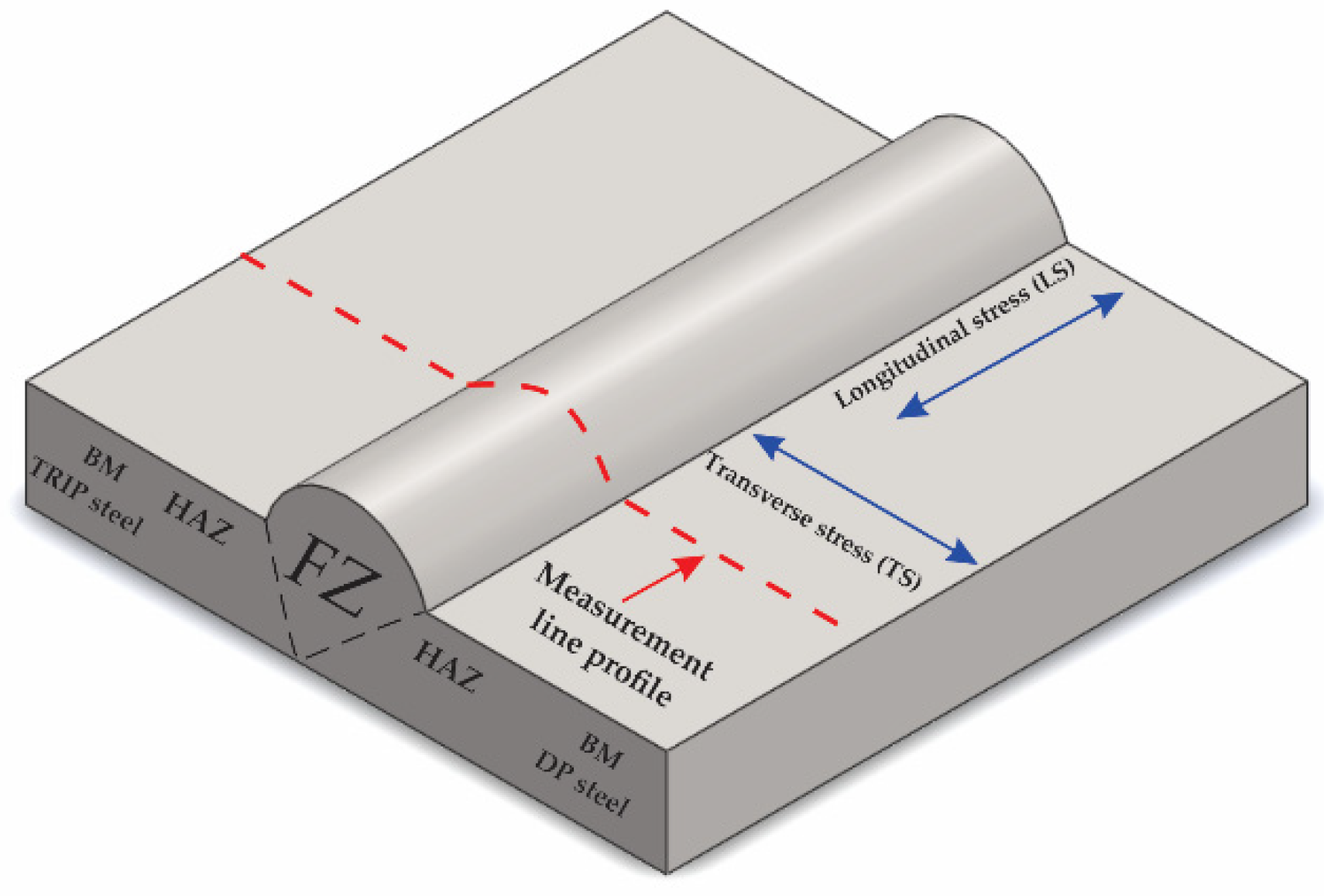
2.4. Residual Stress Measurement

The interplanar spacing d within the crystal lattice can be calculated through the Bragg´s law equation:
n λ = 2 d s i n θ
where θ is the diffraction angle, n and λ are the diffraction order and the wavelength, respectively. If a polycrystalline metal is deformed elastically, the interplanar spacing (strain) within the grains changes to a new value corresponding to the magnitude of the applied stress. X-ray diffraction can be used as a method for strain measurement by tracking the changes in the interplanar spacing d, which can be further related to the elastic strain (ε) according to:
ε = d n d 0 d 0
where dn is the spacing of the planes under stress and d0 is the spacing of the same planes in the absence of stress. The strain is then related to stress (σ) by:
σ y = E ε y
where E is the elastic modulus. If the material is isotropic, the strains are related by:
ε x = ε z = ν ε y
where ν is the Poisson ratio for the material. By combining Equations (2)–(4):
σ y = E ν ( d n d 0 d 0 )
where σy is the required stress [39].
The sin2ψ technique can be used to determine the residual stresses existing in a surface layer of polycrystalline materials by assuming plane-stress state. A number of XRD measurements are made at different psi (ψ) tilt angles, the interplanar spacing (at 2θ peak position) is measured and plotted against the sin2ψ, and the slope of the plot gives σ0, according to [40]:
d ϕ ψ = [ ( 1 + ν E ) · s i n 2 ( ψ ) ( 2 ν E ) ] · σ · d 0 + d 0
Residual surface stresses were experimentally measured by X-ray diffraction through the sin2ψ method at different locations across the weldment (i.e., the measurement line covered: FZ, HAZ, and BM) in both steels of the dissimilar steel sheet combination, as schematically illustrated in Figure 3.
A Bruker Advanced D8 Eco™ diffractometer (Bruker, Zacatecas, Mexico) equipped with Cu radiation adapted with a micro-diffraction pin of 1.0 mm size was employed. The stress analysis was recorded from 115° ≤ 2θ ≤ 118° in order to evaluate α-Fe (310) diffraction peak. A step size of 0.005° and 3 s of time per step were set up. With the purpose of discriminating Fe Kα doublet fluorescence owing to the employment of Cu-kα radiation, a compound silicon strip energy-discriminating-dispersive LYNXEYE XE-T™ detector (Bruker, Zacatecas, México) was suitably calibrated. Residual stresses were calculated from the experimental data (five different ψ angles starting at 0° up to 45°) throughout the slope of the least-square line method by supposing material constant values E = 181 GPa, and Poisson ratio v = 0.32. The lattice spacing d0 in this experiment was measured at Ψ = 0 because elastic strains do not introduce more than 0.1% difference between the true d0 and d at any ψ [39]. Gravity peak positioning method for the quantitative XRD stress evaluation was carried out (by using LEPTOSTM software, version 7.8 build 0-S, Bruker AXS GmbH, Zacatecas, México), as this approach is categorized for providing best linear regressions, thus resulting in high precision [40]. The accuracy of stress measurements lied approximately within a range of ±21~35 MPa.

3. Results and Discussion

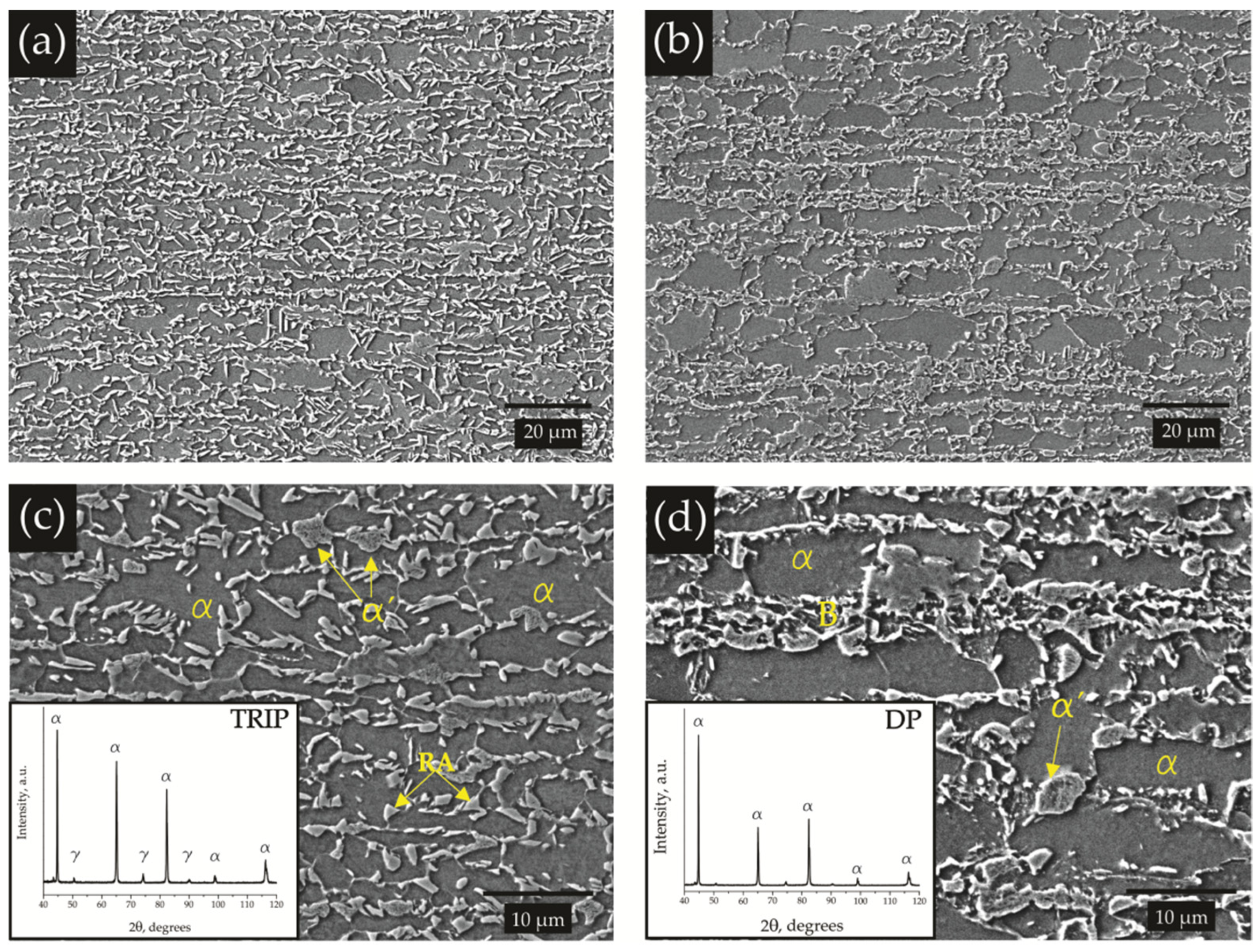
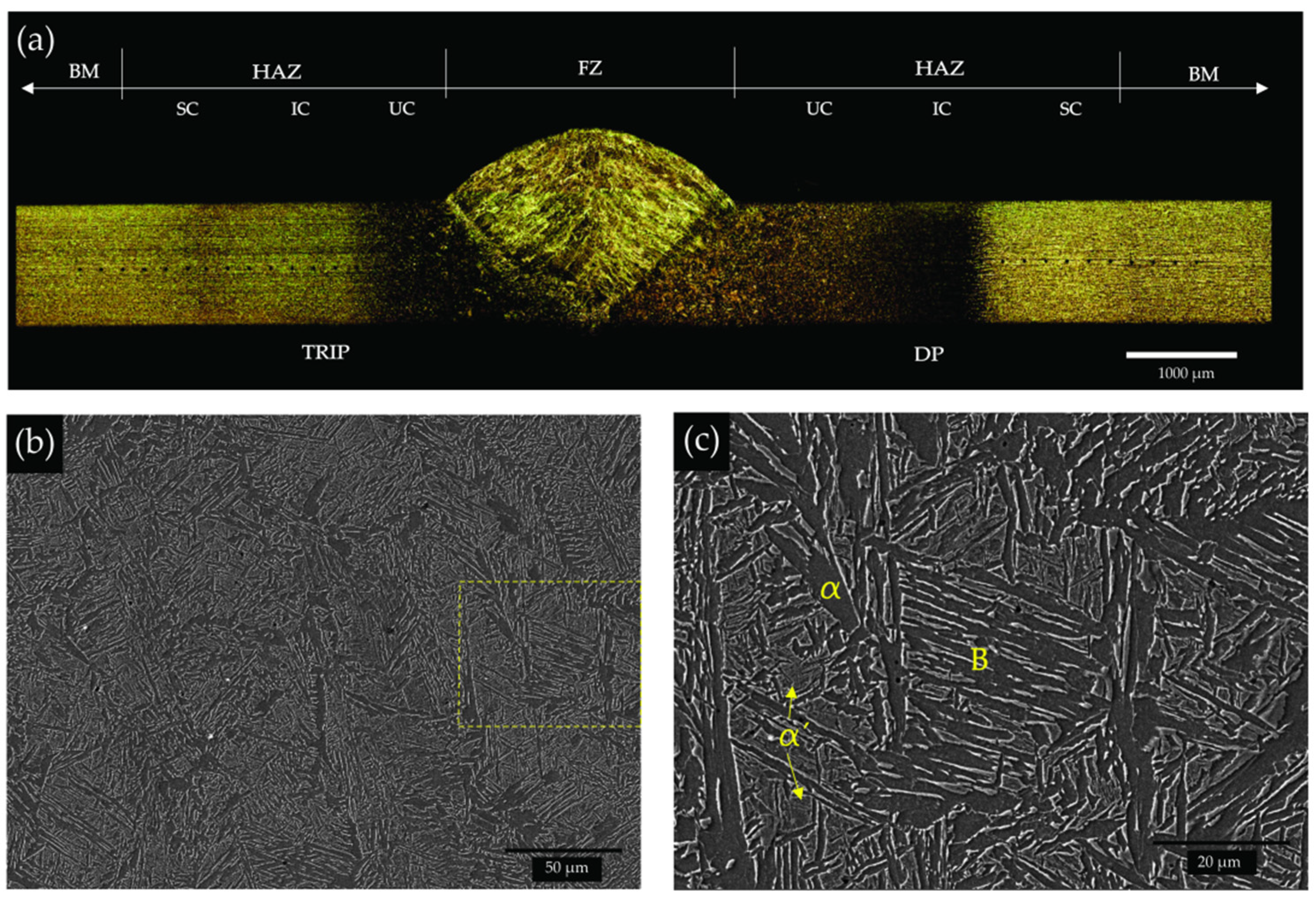
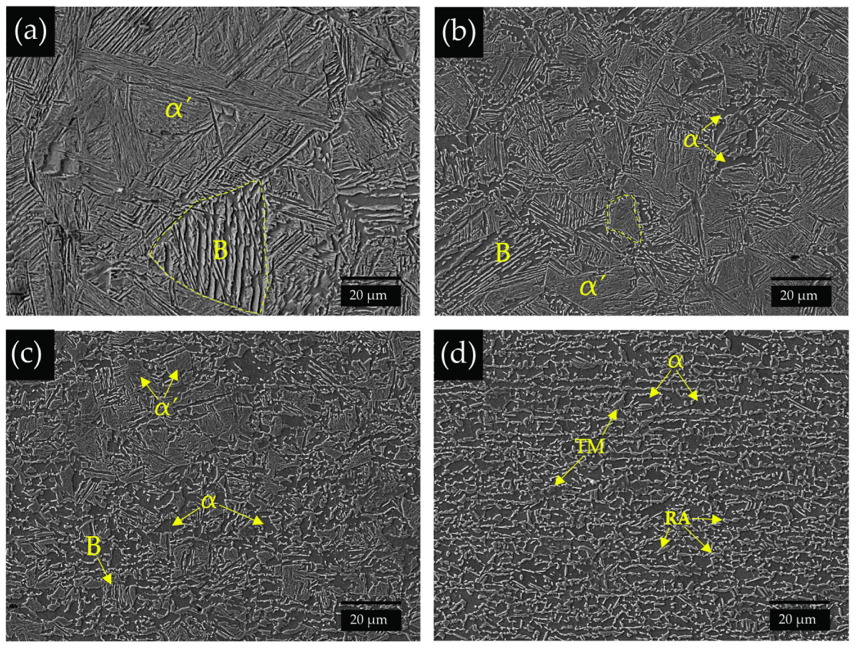
3.1. Microstructure and Hardness

Figure 4a shows the transverse cross-section macrostructure of the GMAW specimen, indicating the location of the various regions within the weldment, i.e., the fusion zone (FZ), the heat-affected zone (HAZ) that was subdivided as specific zones corresponding to the upper-critical (UC-HAZ), inter-critical (IC-HAZ), and sub-critical (SC-HAZ), and finally, the base metal (BM) has also been pointed out.
The FZ microstructure of the GMAW specimen is shown in Figure 4b,c. The area marked with a yellow square within Figure 4b can be observed at higher magnification in Figure 4c. Due to the mixture of the chemistry between the TRIP, DP, and filler metal, the high heat input and the corresponding cooling rate and a high-volume fraction of ferrite, side-plate ferrite, the reduced content of perlite, and a considerable fraction of bainite and martensite are the main FZ constituents, as illustrated in detail in Figure 4c.
The net high heat input upon the GMAW process promoted a great extension of the weldment zone and the microstructure gradient along the HAZ is described as follows. The microstructure of the TRIP steel UC-HAZ is composed of coarse-grain and fine-grain zones with predominant martensite and bainite with a reduced fraction of ferrite located at the prior austenite grain boundary, and it is important to notice that the periphery of the prior austenite grain boundary (an indication of the grain size) has been finely delimited by a dashed line in selected grains in Figure 5a,b. The IC-HAZ which is a partially transformed zone revealed the previous TRIP-BM microstructure along with the further products of the transformation, such as martensite and bainite, as seen in Figure 5c. The SC-HAZ shows the presence of ferrite, tempered martensite (TM), and traces of retained austenite, as illustrated in the Figure 5d.
In the same way as the TRIP steel, Figure 6a,b show both coarse- and fine-grain regions in the UC-HAZ in the DP steel side; however, the predominant martensite is further revealed. Again, the DP-IC-HAZ is composed of the BM microstructure and the transformed microstructure of martensite and traces of bainite (Figure 6c). Meanwhile, the precipitation of carbides due to the tempering of martensite is clearly evident in the SC-HAZ of the DP side (Figure 6d).
The macrostructure of the laser-welded TRIP-DP specimen observed in Figure 7a illustrates a narrow weldment zone (FZ and HAZ) as compared to the GMAW specimen. The high cooling rate developed in the LBW process evidently resulted in the formation of a hard martensitic microstructure in the fusion zone, as shown in Figure 7b,c. Again, the marked area within Figure 7b can be observed at higher magnification in Figure 7c.
The microstructure development of the laser-welded TRIP-DP specimen for both HAZs is observed in Figure 8. The TRIP-UC-HAZ revealed finer martensite grains (as compared to the GMAW specimen), a narrow TRIP-IC-HAZ showing partial transformation, and the SC-HAZ with the presence of ferrite and hardly observed tempered martensite (almost inexistent). A similar trend is shown on the DP steel side: martensite in the UC-HAZ, a partial transformation of microstructures in the IC-HAZ, and the barely observed TM in the SC-HAZ.
The hardness profile distribution throughout the weldment for the GMAW and LBW are given in Figure 9a,b. The GMAW specimen FZ hardness averaged 284 ± 10 HV which corresponded well to the previously described microstructures; in addition, the peak hardness value (415 HV) was measured in the UC-HAZ on the DP steel side in which the predominant martensite and bainite were obtained. A transitional reduction in hardness is clearly seen in the IC-HAZ (particularly on the DP side). Softening in the SC-HAZ is revealed in both steels with a hardness drop (44 HV) in the DP steel (with respect to the BM) and a drop of hardness (35 HV) in the TRIP steel side (Figure 9a). Softening in the HAZ of the GMAW-TRIP steel has been previously reported, and it has been attributed to: (a) the precipitation and coarsening of carbides, (b) the precipitation of the supersaturated austenite phase, and (c) the partial recovery of the lath martensite [26]. On the other hand, the LBW specimen showed a sharper hardness profile, as observed in Figure 9b, with a maximum hardness value logically encountered in the FZ averaging 461 ± 24 HV. A transitional drop in hardness in the HAZ is observed in both steels, whereas nonmeasurable softening was found on either steel side of the dissimilar joint.

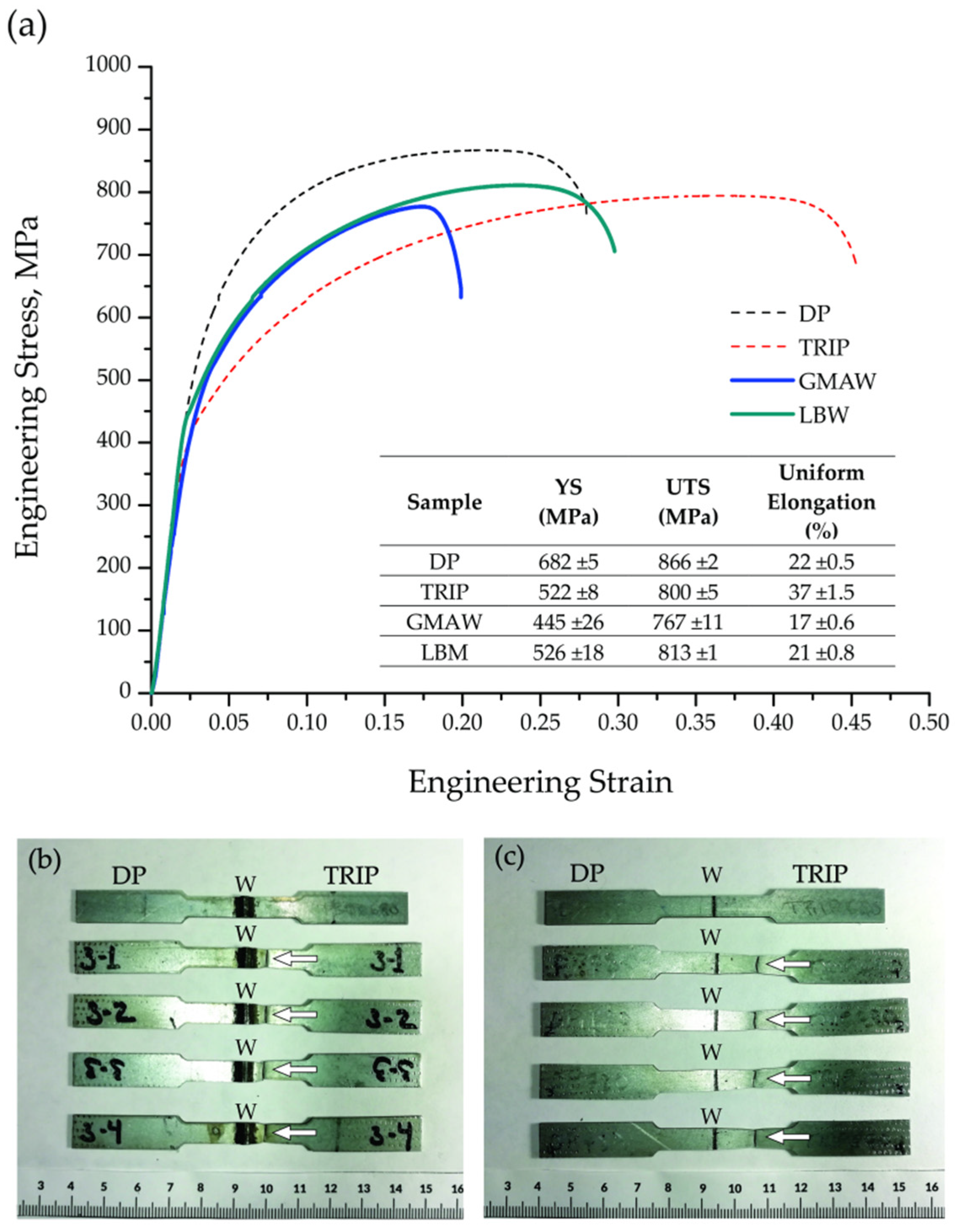
3.2. Uniaxial Tensile Behavior

The engineering stress–strain curves of the welded specimens in Figure 10a show that the uniform elongation and UTS for the LBW was 21% and 813 MPa, respectively, which contrast well to the diminished values for the GMAW specimen (17% and 767 MPa). In addition, the BM tensile properties incorporated as a benchmark in Figure 10a indicate that the mechanical overall performance is being obviously affected in the welded specimens; furthermore, the higher the input, the higher the extension of the weldment, therefore lessening the final tensile properties in the GMAW specimen [26]. It is worth noting that the stress–strain curve of the welded joints was approximately the average of the stress–strain curve of both base materials; hence, this is an indication that all elements of the joints were being strained until strain localization occurred.
The failure location for the GMAW and LBW specimens consistently resulted on the TRIP steel side; however, it is worth to note that the failure was consistently located in the SC-HAZ of the GMAW specimen as pointed out by the white arrows in Figure 10b. Contrary to that, the LBW specimen failed at 12 mm away from the center of the FZ, therefore confirming that the failure location corresponded to the TRIP-BM (Figure 10c).

3.3. Residual Stress Analysis

Figure 11 shows the residual stress (RS) profiles across the weldment of both (a) GMAW and (b) LBW specimens. The negative stresses located in the FZ of the gas metal arc weld dissimilar steel combination clearly contrast the positive stress distribution in the HAZ in both steels, as observed in Figure 11a. The transverse stress (TS) along the HAZ in both steels is generally higher as compared to the longitudinal stress (LS); further, the peak stress value was found in the HAZ of the TRIP steel side (421 MPa). In contrast, the LS distribution along the HAZ (UC, IC, SC) region is for the most part higher on the DP side, whereas in the HAZ of the TRIP steel side, the LS resulted almost near to zero (Figure 11a). Finally, it is important to mention that both types of residual stress (LS and TS) are higher in the base metal of the TRIP steel side.
Compressive residual stresses in the fusion FZ of high-strength steel arc weldments have likewise been reported elsewhere [31,33,35]. It has been established that the resultant RS distribution within the weld zone in arc welds largely depends on the careful selection of the filler metal; the richer the chemistry of the filler metal (i.e., additions of Cr, Ni, Mn, etc.), the higher the tendency to develop a harder martensitic microstructure that could control the evolution of the tensile residual stresses in the FZ [31,41]. Martensite displacive transformation occurs at lower temperatures (~250 °C) as compared to bainite (~400 °C), ferrite, and/or pearlite (~700 °C), and the RS generated are much smaller due to the smaller range between the martensite finish and room temperature that further minimizes thermal contractions. Phase transformation strains overtake the effect of thermal contraction as the temperature decreases; as soon as the austenite phase is depleted, the thermal contraction continues, thus producing the accumulation of stress. Therefore, the displacive transformation leads to a greater reduction in stress and the possibility of turning it into compressive stresses [42]. However, the FZ of the GMAW specimen in the dissimilar TRIP-DP combination resulted in a combination of various phases, including martensite, bainite, and ferrite (Figure 4), and the average FZ hardness was measured below 300 HV (Figure 9a); therefore, it is seen that the resultant compressive stress in the FZ did not solely depend on the transformation of the previously described phases but on the possible additional factors, such as the weld joint restraint [43], the sheet thickness, the type of joint [44], the weld reinforcement size [45], the effects of the dissimilar steel type (mismatch properties) [46], among others. The former variables are being further investigated and results will be communicated in future contributions.
On the other hand, there is a clear trend in the HAZ of the GMAW specimens associated to the gradual increase in residual stresses to a maximum value, then followed by a steady decrease up to the base metal (see Figure 11a); a similar trend has been reported elsewhere [31,35,36]. Two evident RS values are revealed in the UC-HAZ of both steels. For instance, the high RS value is located in the coarse-grain region (next to the fusion line), whereas the maximum RS value is located just in the fine-grain region, and in both mentioned regions, the hard lath martensite is the predominant phase as observed in Figure 5a,b and Figure 6a,b. On the contrary, there is a combination of soft and hard phases in the IC-HAZ region due to partial recrystallization and further transformation into hard martensite and bainite, and the mixture of the partial recrystallized structure and the unaffected BM microstructure further lowered the RS values (Figure 5c and Figure 6c). The tempering of the martensite phase and the low annealing temperature occurring in the SC-HAZ resulted in a further reduction in the RS values; indeed, carbide precipitation in the martensite islands (Figure 6d) along with a severe hardness reduction (Figure 9) was evident in the SC-HAZ of the DP steel which resulted in the lowest RS values as compared to the TRIP side. It has been previously demonstrated [24,26] that softening due to the tempering of martensite is quite more accentuated in DP steels in comparison with TRIP steels; therefore, a larger RS reduction was seen in the DP side of the dissimilar GMAW combination, as confirmed in Figure 11a.
It is important to mention that maximum tensile residual stresses have been consistently reported to be located in the HAZ of AHSSs arc weldments [31,33,35,36]. The higher tensile residual stress in the HAZ has been correlated to the thermal diffusivity distribution, and therefore to the heat concentration in the HAZ adjacent to the FZ that promotes high thermal stresses [36]. Furthermore, it has been consistently correlated that the maximum values of the RS (i.e., located in the HAZ) to the bulk material yield strength (YS); in some cases, the former reaches half of the YS [35,36] and, in other cases, is close to the YS [33]. Thereby, it is shown here that there is a microstructure gradient along the HAZ that promotes property variations, particularly on the localized yield strength. For example, it has been demonstrated that the temperature-dependent yield strength of austenite, bainite, and/or martensite are different and have particular variations that greatly influence the residual stresses in the HAZ [47].
On the other hand, the residual stress profile of the LBW specimen resulted almost in a flat shape, as depicted in Figure 11b. Tensile longitudinal stresses and compressive transverse stresses are revealed in the narrow FZ; however, it is important to recall that the width of the FZ is about 450 µm. The maximum RS value (172 MPa tensile) was located in the HAZ of the DP steel side. The difficulties associated to the limited and small size of the HAZ (250–300 µm) in the LBW specimen made it hard to differentiate the corresponding experimental residual stresses of the various subzones (UC, IC, SC); therefore, the RS indicated in Figure 11b is, without any doubt, representative of all the mentioned subzones. Once the RS measurement location is far away from the HAZ, the residual stresses in the base metal in both steels again seemed to be mainly negative and about zero. Correspondingly, the tensile longitudinal RS and the compressive transverse RS have been reported in the FZ of a TRIP steel paired to a TWIP steel through Nd:YAG laser welding, whereas elevated RS values were located in the HAZ of the TRIP steel side and compressive stresses were consistently reported in the BM [37].
Generally speaking, the abovementioned residual stress state in the LBW specimen is expectedly lower than that encountered in the GMAW specimen. The higher heat input in the arc welding processes obviously induced higher distortion in the dissimilar TRIP-DP steel sheet combination. Additionally, it has been documented that arc welding heat input can be several times higher than the laser welding heat input, thus inducing higher residual stress in the former [43,48]. Indeed, the employment of a filler metal and consequently the volume addition of metal promotes a shrinkage effect in the arc welding process, thus inducing high tensile stresses at the weldment (distinctly in the HAZ) that clearly contrast the overall compressive stresses typically found upon laser weldments [49,50].
On the other hand, the maximum FZ hardness was found in the LBW specimen (i.e., above 450 HV) having the presence of predominant lath martensite; the average RS value was considerably lower in comparison to the HAZ, thus meaning that martensitic transformation could further relax the residual stresses [32]. Finally, according to Figure 10, the failure location in both welded specimens GMAW and LBW resulted in the SC-HAZ and the BM, respectively, on the TRIP steel side; hence, it can be inferred here that the resultant residual stress distribution had no clear influence on the uniaxial tensile behavior in both the GMAW and LBW specimens. However, it is worth mentioning that further investigation is needed in order to understand the effect of the RS distribution along the weldment on the fatigue, impact, and/or formability behavior of arc and laser welding of AHSSs.

4. Conclusions

A dissimilar steel-grade combination of the TRIP-DP was butt-joined by separately employing two different welding processes: GMAW and LBW. The post-weld microstructure description of the different regions of the weldment has been provided along with the corresponding hardness measurements, and the uniaxial tensile behavior and the residual stress distribution across the weldment were analyzed; therefore, the following conclusions are addressed.
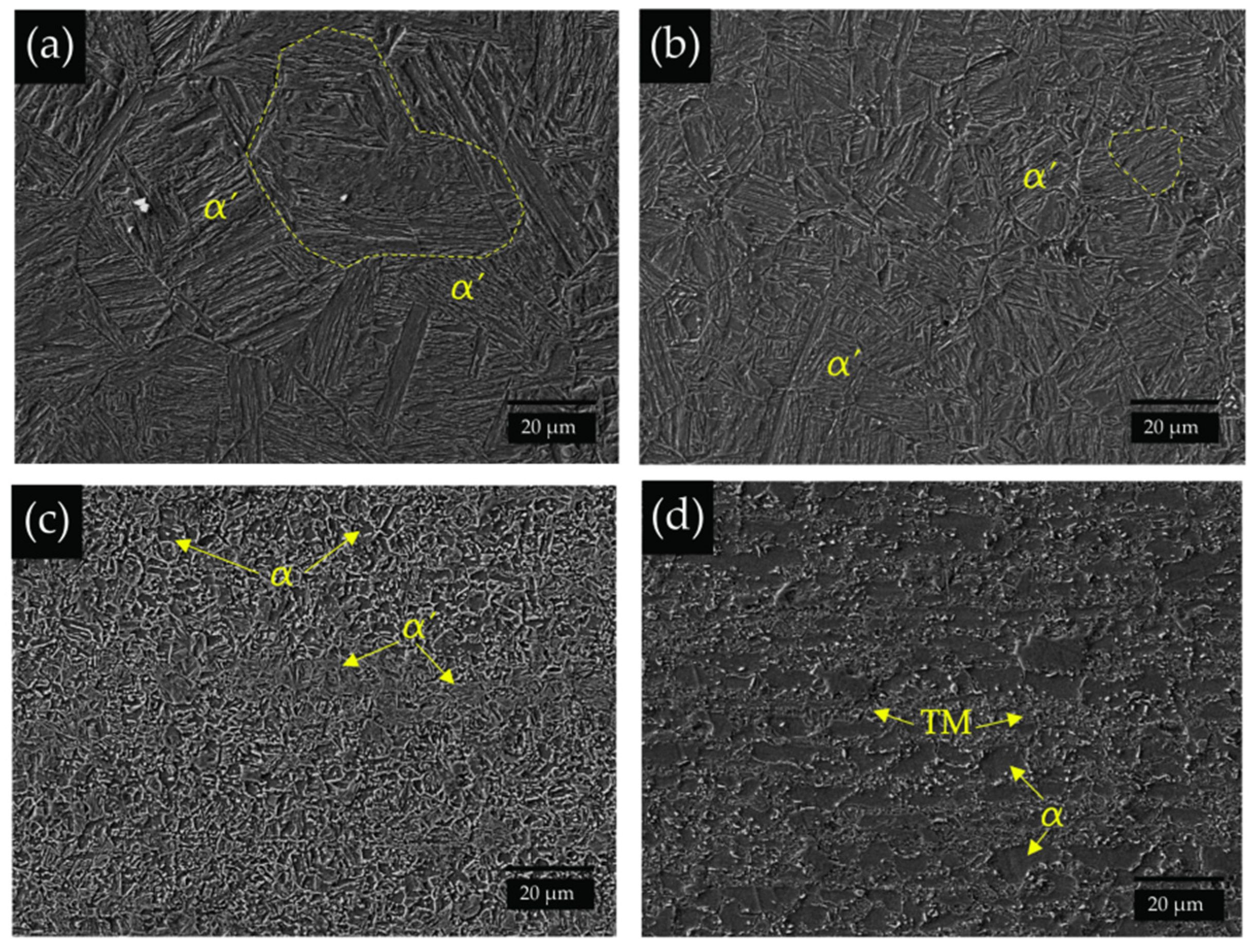
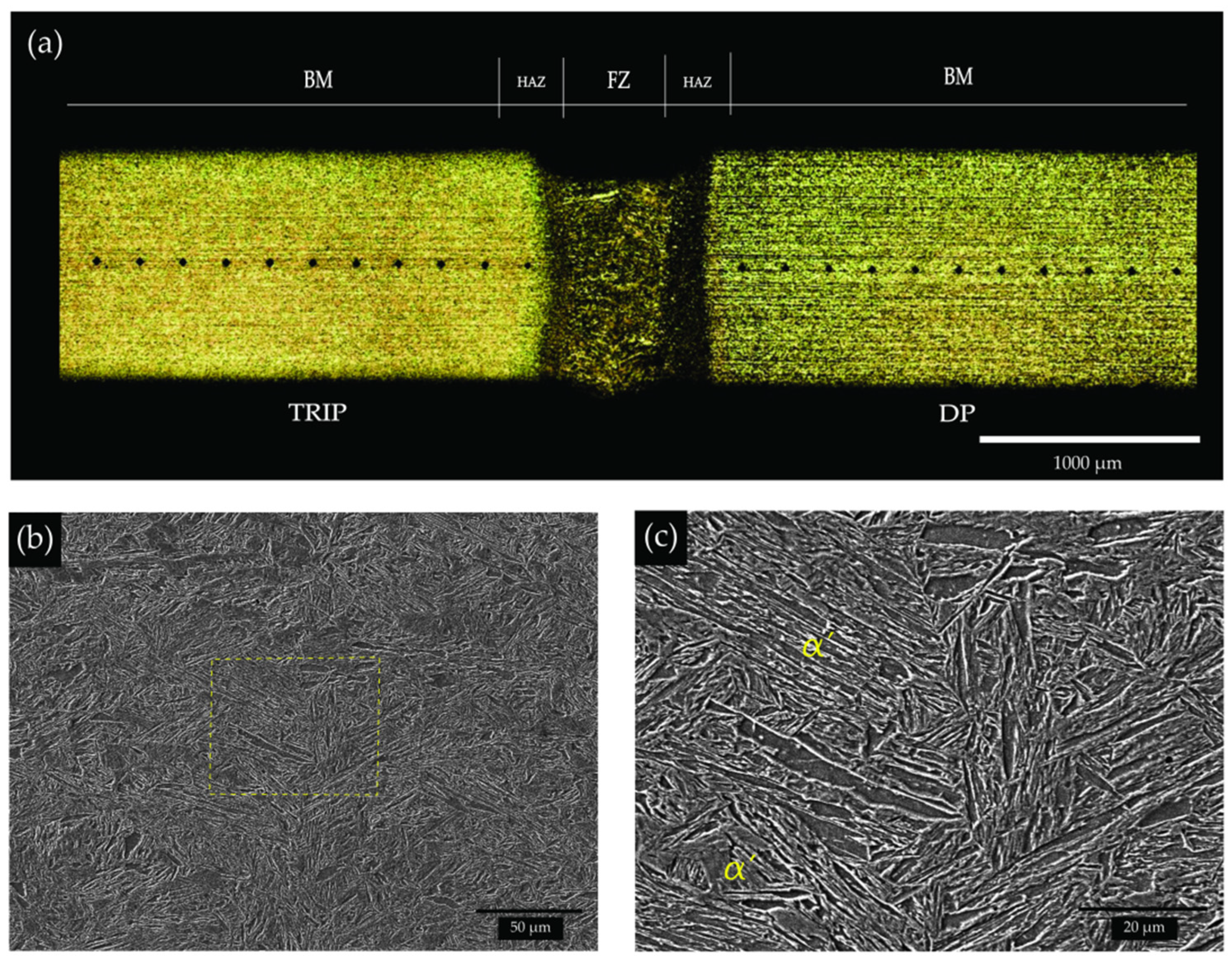
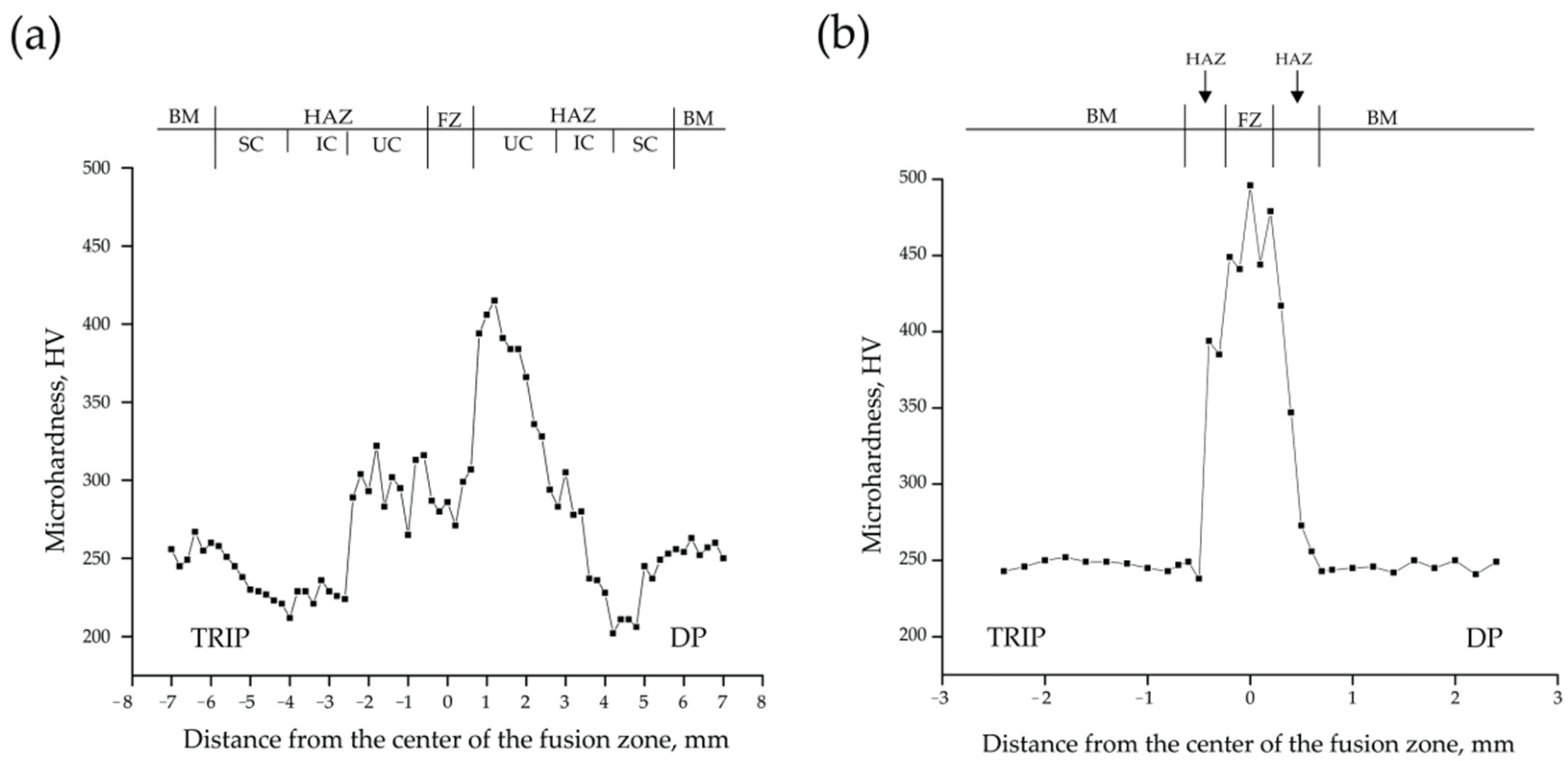
  • A hard predominant martensite averaging 461 ± 24 HV in the FZ of the LBW specimen contrasts well with the 284 ± 10 HV obtained in the FZ of the GMAW due to the combination of ferrite, bainite, and martensite microstructures promoted by the mix of chemistry between the filler metal and the base material in the latter.
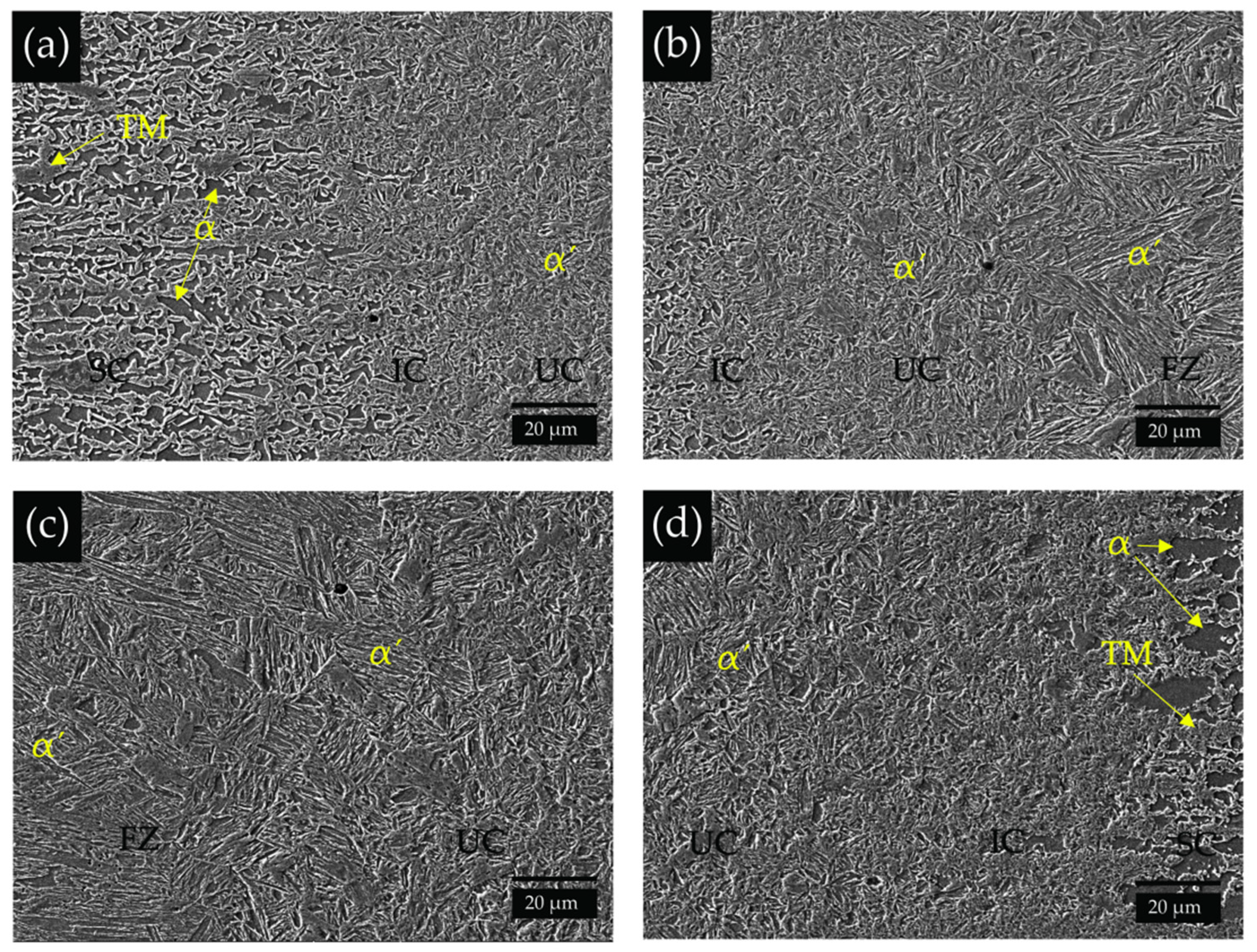
  • The peak hardness value (415 HV) measured in the UC-HAZ of the DP steel side in the GMAW specimen clearly contrasted with the peak value (322 HV) on the TRIP steel side due to the presence of a reduced fraction of ferrite located at the prior austenite grain boundary in the latter.
  • Although the mechanical behaviors of the base materials are clearly superior, the improved uniaxial tensile weld properties in the LBW specimen (UTS = 813 MPa) contrasted well to the GMAW weldment (UTS = 767 MPa), whereas the failure location was found in the BM in the LBW specimen, and the location of failure was localized in the SC-HAZ of the GMAW specimen. In both cases, the failure resulted on the TRIP steel side.
  • In spite of the combination of ferrite, bainite, and martensite microstructures found in the fusion zone of the GMAW specimen, the measured compressive residual stresses cannot be solely attributed to the phase transformation but to other possible factors, such as the material mismatch properties, the reinforcement size, the type of joint, the sheet thickness, and the weld joint restraint.
  • The gradual increasing of residual stresses to a maximum value was followed by a steady decrease up to the base metal; the trend ensued: UC-HAZ (maximum) → IC-HAZ (moderated) → SC-HAZ (lowered). That trend was particularly evident in the GMAW specimen.
  • The experimental surface residual stress distribution along the weldment measured in the LBW specimen is clearly lower if comparing it to the GMAW specimen. The maximum RS value (172 MPa tensile) was measured in the HAZ of the DP side which clearly contrasts to the maximum value (421 MPa) measured in the HAZ of the TRIP steel in the GMAW specimen.
  • The resultant tensile residual stress distribution in both the GMAW and LBW specimens had no direct influence on the uniaxial tensile behavior of the welded specimens due to the failure location in both cases occurring on the TRIP steel side, either in the SC-HAZ in the case of the GMAW or in the BM in the LBW specimen.

Author Contributions

Conceptualization-data curation, V.H.B.-H. and E.A.L.-B.; formal analysis, V.H.B.-H., S.G.-J. and J.J.R.-M.; investigation, V.H.B.-H.; methodology, V.H.B.-H.; validation, E.A.L.-B.; writing—original draft, V.H.B.-H. and E.A.L.-B.; writing—review and editing, F.A.-H., E.B. and N.Z. All authors have read and agreed to the published version of the manuscript.

Funding

This research was funded by the Universidad Autónoma de Zacatecas, Centre for Advanced Materials Joining, University of Waterloo, and COMIMSA, Mexico. Project UAZ-2019-37808.

Acknowledgments

V.H.B.-H. wants to acknowledge the technician Angel Gonzalez Ramos for his support in the metallographic sampling. V.H.B.-H. wants to acknowledge the technician ofthe X-ray laboratory facilities at the UAZ for the residual stress trials.

Conflicts of Interest

The authors declare no conflict of interest.

References

  1. Jiang, H.; Liao, Y.; Gao, S.; Li, G.; Cui, J. Comparative study on joining quality of electromagnetic driven self-piecing riveting, adhesive and hybrid joints for Al/steel structure. Thin-Walled Struct. 2021, 164, 107903. [Google Scholar] [CrossRef]
  2. Jiang, H.; Liao, Y.; Jing, L.; Gao, S.; Li, G.; Cui, J. Mechanical properties and corrosion behavior of galvanized steel/Al dissimilar joints. Arch. Civ. Mech. Eng. 2021, 21, 168. [Google Scholar] [CrossRef]
  3. WorldAutoSteel. AHSS Guidelines. Available online: https://www.worldautosteel.org/projects/advanced-high-strength-steel-application-guidelines/ (accessed on 31 March 2022).
  4. Hernandez, B.V.H.; Kuntz, M.L.; Khan, M.I.; Zhou, Y. Influence of microstructure and weld size on the mechanical behaviour of dissimilar AHSS resistance spot welds. Sci. Technol. Weld. Join. 2008, 13, 769–776. [Google Scholar] [CrossRef]
  5. Shome, M.; Tumuluru, M. 1—Introduction to welding and joining of advanced high-strength steels (AHSS). In Welding and Joining of Advanced High Strength Steels (AHSS); Shome, M., Tumuluru, M., Eds.; Woodhead Publishing: Sawston, UK, 2015; pp. 1–8. [Google Scholar] [CrossRef]
  6. Duchet, M.; Haouas, J.; Gibeau, E.; Pechenot, F.; Honecker, C.; Munier, R.; Weber, B. Improvement of the fatigue strength of welds for lightweight chassis application made of Advanced High Strength Steels. Procedia Struct. Integr. 2019, 19, 585–594. [Google Scholar] [CrossRef]
  7. John, M.; Kumar, A.; Bhat, U. AHSS welding using undermatching filler wires and process advantages with P-GMAW. Mater. Today Proc. 2022, 49, 1312–1318. [Google Scholar] [CrossRef]
  8. Kapustka, W.M.a.N. Fatigue of GMAW-P Lap Joints in Advanced High-Strength Steels. In Proceedings of the Sheet Metal Welding Conference XVIII Livonia, Livonia, MI, USA, 17–18 October 2018. [Google Scholar]
  9. Ahiale, G.K.; Oh, Y.-J. Microstructure and fatigue performance of butt-welded joints in advanced high-strength steels. Mater. Sci. Eng. A 2014, 597, 342–348. [Google Scholar] [CrossRef]
  10. Svoboda, H.G.; Nadale, H.C. Fatigue Life of GMAW and PAW Welding Joints of Boron Microalloyed Steels. Procedia Mater. Sci. 2015, 9, 419–427. [Google Scholar] [CrossRef] [Green Version]
  11. Sharifimehr, S.; Fatemi, A.; Cha, S.C.; Bae, M.-K.; Hong, S.-H. Fatigue behavior of AHSS lap shear and butt arc welds including the effect of periodic overloads and underloads. Int. J. Fatigue 2016, 87, 6–14. [Google Scholar] [CrossRef]
  12. Tong, L.; Niu, L.; Ren, Z.; Zhao, X.-L. Experimental investigation on fatigue behavior of butt-welded high-strength steel plates. Thin-Walled Struct. 2021, 165, 107956. [Google Scholar] [CrossRef]
  13. Zhang, M.; Li, L.; Fu, R.-y.; Zhang, J.-c.; Wan, Z. Weldability of low carbon transformation induced plasticity steel. J. Iron Steel Res. Int. 2008, 15, 61–65. [Google Scholar] [CrossRef]
  14. Májlinger, K.; Kalácska, E.; Russo Spena, P. Gas metal arc welding of dissimilar AHSS sheets. Mater. Des. 2016, 109, 615–621. [Google Scholar] [CrossRef]
  15. Varol, F.; Ferik, E.; Ozsarac, U.; Aslanlar, S. Influence of current intensity and heat input in Metal Inert Gas-brazed joints of TRIP 800 thin zinc coated steel plates. Mater. Des. 2013, 52, 1099–1105. [Google Scholar] [CrossRef]
  16. Njock Bayock, F.; Kah, P.; Mvola, B.; Layus, P. Effect of Heat Input and Undermatched Filler Wire on the Microstructure and Mechanical Properties of Dissimilar S700MC/S960QC High-Strength Steels. Metals 2019, 9, 883. [Google Scholar] [CrossRef] [Green Version]
  17. Bandyopadhyay, K.; Panda, S.K.; Saha, P.; Baltazar-Hernandez, V.H.; Zhou, Y.N. Microstructures and failure analyses of DP980 laser welded blanks in formability context. Mater. Sci. Eng. A 2016, 652, 250–263. [Google Scholar] [CrossRef]
  18. Basak, S.; Katiyar, B.; Orozco-Gonzalez, P.; Baltazar-Hernandez, V.; Arora, K.; Panda, S. Microstructure, forming limit diagram, and strain distribution of pre-strained DP-IF steel tailor–welded blank for auto body application. Int. J. Adv. Manuf. Technol. 2019, 104, 1749–1767. [Google Scholar] [CrossRef]
  19. Yuce, C.; Tutar, M.; Karpat, F.; Yavuz, N. The Optimization of Process Parameters and Microstructural Characterization of Fiber Laser Welded Dissimilar HSLA and MART Steel Joints. Metals 2016, 6, 245. [Google Scholar] [CrossRef] [Green Version]
  20. Evin, E.; Tomáš, M. The Influence of Laser Welding on the Mechanical Properties of Dual Phase and Trip Steels. Metals 2017, 7, 239. [Google Scholar] [CrossRef] [Green Version]
  21. Xue, X.; Pereira, A.; Amorim, J.; Liao, J. Effects of Pulsed Nd:YAG Laser Welding Parameters on Penetration and Microstructure Characterization of a DP1000 Steel Butt Joint. Metals 2017, 7, 292. [Google Scholar] [CrossRef]
  22. He, H.; Forouzan, F.; Volpp, J.; Robertson, S.M.; Vuorinen, E. Microstructure and Mechanical Properties of Laser-Welded DP Steels Used in the Automotive Industry. Materials 2021, 14, 456. [Google Scholar] [CrossRef]
  23. Lee, J.H.; Park, S.H.; Kwon, H.S.; Kim, G.S.; Lee, C.S. Laser, tungsten inert gas, and metal active gas welding of DP780 steel: Comparison of hardness, tensile properties and fatigue resistance. Mater. Des. 2014, 64, 559–565. [Google Scholar] [CrossRef]
  24. Sun, Q.; Di, H.-S.; Li, J.-C.; Wu, B.-Q.; Misra, R.D.K. A comparative study of the microstructure and properties of 800 MPa microalloyed C-Mn steel welded joints by laser and gas metal arc welding. Mater. Sci. Eng. A 2016, 669, 150–158. [Google Scholar] [CrossRef]
  25. Němeček, S.; Mužík, T.; Míšek, M. Differences between Laser and Arc Welding of HSS Steels. Phys. Procedia 2012, 39, 67–74. [Google Scholar] [CrossRef] [Green Version]
  26. Guzman-Aguilera, J.J.; Martinez-Gonzalez, C.J.; Baltazar-Hernandez, V.H.; Basak, S.; Panda, S.K.; Razmpoosh, M.H.; Gerlich, A.; Zhou, Y. Influence of SC-HAZ microstructure on the mechanical behavior of Si-TRIP steel welds. Mater. Sci. Eng. A 2018, 718, 216–227. [Google Scholar] [CrossRef]
  27. Khanna, S.K.; Long, X. Residual stresses in resistance spot welded steel joints. Sci. Technol. Weld. Join. 2008, 13, 278–288. [Google Scholar] [CrossRef]
  28. Colombo, T.C.A.; Rego, R.R.; Otubo, J.; de Faria, A.R. Mechanical reliability of TWIP steel spot weldings. J. Mater. Process. Technol. 2019, 266, 662–674. [Google Scholar] [CrossRef]
  29. Shamsujjoha, M.; Enloe, C.M.; Chuang, A.C.; Coryell, J.J.; Ghassemi-Armaki, H. Mechanisms of paint bake response in resistance spot-welded first and third generation AHSS. Materialia 2021, 15, 100975. [Google Scholar] [CrossRef]
  30. Ren, S.; Ma, N.; Tsutsumi, S.; Watanabe, G.; He, H.; Cao, C.; Huang, L. Post-weld cold working for fatigue strength improvement of resistance spot welded joint of advanced high-strength steel. J. Mater. Process. Technol. 2022, 299, 117364. [Google Scholar] [CrossRef]
  31. Wu, X.I.N.; Wang, Z.; Yu, Z.; Liu, S.; Bunn, J.R.; Kolbus, L.; Feng, Z. Control of Weld Residual Stress in a Thin Steel Plate through Low Transformation Temperature Welding Consumables. Weld. J. 2020, 99, 124s–134s. [Google Scholar] [CrossRef]
  32. Kouadri-Henni, A.; Seang, C.; Malard, B.; Klosek, V. Residual stresses induced by laser welding process in the case of a dual-phase steel DP600: Simulation and experimental approaches. Mater. Des. 2017, 123, 89–102. [Google Scholar] [CrossRef] [Green Version]
  33. Lin, J.; Ma, N.; Lei, Y.; Murakawa, H. Measurement of residual stress in arc welded lap joints by cosα X-ray diffraction method. J. Mater. Process. Technol. 2017, 243, 387–394. [Google Scholar] [CrossRef]
  34. Kang, H.T.; Lee, Y.-L.; Sun, X.J. Effects of residual stress and heat treatment on fatigue strength of weldments. Mater. Sci. Eng. A 2008, 497, 37–43. [Google Scholar] [CrossRef]
  35. Kong, F.; Kovacevic, R. Measurement of surface residual stresses and testing mechanical properties of high-strength steel butt joints obtained by hybrid laser/gas metal arc welding. J. Strain Anal. Eng. Des. 2013, 48, 437–445. [Google Scholar] [CrossRef]
  36. García-García, V.; Mejía, I.; Reyes-Calderón, F.; Benito, J.A.; Cabrera, J.M. FE thermo-mechanical simulation of welding residual stresses and distortion in Ti-containing TWIP steel through GTAW process. J. Manuf. Process. 2020, 59, 801–815. [Google Scholar] [CrossRef]
  37. Mujica, L.; Weber, S.; Pinto, H.; Thomy, C.; Vollertsen, F. Microstructure and mechanical properties of laser-welded joints of TWIP and TRIP steels. Mater. Sci. Eng. A 2010, 527, 2071–2078. [Google Scholar] [CrossRef]
  38. Kasuya, T.; Yurioka, N. Determination of Necessary Preheat Temperature to Avoid Cold Cracking under Varying Ambient Temperature. ISIJ Int. 1995, 35, 1183–1189. [Google Scholar] [CrossRef]
  39. Cullity, B.D. Elements of X-ray Diffraction; Prentice Hall: Hoboken, NJ, USA, 1978; pp. 435–469. [Google Scholar]
  40. Luo, Q.; Jones, A.H. High-precision determination of residual stress of polycrystalline coatings using optimised XRD-sin2ψ technique. Surf. Coat. Technol. 2010, 205, 1403–1408. [Google Scholar] [CrossRef] [Green Version]
  41. Ooi, S.W.; Garnham, J.E.; Ramjaun, T.I. Review: Low transformation temperature weld filler for tensile residual stress reduction. Mater. Des. 2014, 56, 773–781. [Google Scholar] [CrossRef]
  42. Francis, J.A.; Bhadeshia, H.K.D.H.; Withers, P.J. Welding residual stresses in ferritic power plant steels. Mater. Sci. Technol. 2007, 23, 1009–1020. [Google Scholar] [CrossRef]
  43. Elmesalamy, A.; Francis, J.A.; Li, L. A comparison of residual stresses in multi pass narrow gap laser welds and gas-tungsten arc welds in AISI 316L stainless steel. Int. J. Press. Vessel. Pip. 2014, 113, 49–59. [Google Scholar] [CrossRef]
  44. Bate, S.K.; Green, D.; Buttle, D. A Review of Residual Stress Distributions in Welded Joints for the Defect Assessment of Offshore Structures; U.S. Department of Energy Office of Scientific and Technical Information: Norwich, UK, 1998; p. 144. ISBN 0717624110.
  45. Hu, X.; Jiang, H.Y.; Luo, Y.; Jin, Q.; Peng, W.; Yi, C.M. A Study on Microstructure, Residual Stresses and Stress Corrosion Cracking of Repair Welding on 304 Stainless Steel: Part II-Effects of Reinforcement Height. Materials 2020, 13, 2434. [Google Scholar] [CrossRef]
  46. Venkata Ramana, P.; Madhusudhan Reddy, G.; Mohandas, T.; Gupta, A.V.S.S.K.S. Microstructure and residual stress distribution of similar and dissimilar electron beam welds—Maraging steel to medium alloy medium carbon steel. Mater. Des. 2010, 31, 749–760. [Google Scholar] [CrossRef]
  47. Sun, J.; Nitschke-Pagel, T.; Dilger, K. Influence of temperature- and phase-dependent yield strength on residual stresses in ultra-high strength steel S960 weldments. J. Mater. Res. Technol. 2021, 15, 1854–1872. [Google Scholar] [CrossRef]
  48. Balakrishnan, J.; Vasileiou, A.N.; Francis, J.A.; Smith, M.C.; Roy, M.J.; Callaghan, M.D.; Irvine, N.M. Residual stress distributions in arc, laser and electron-beam welds in 30 mm thick SA508 steel: A cross-process comparison. Int. J. Press. Vessel. Pip. 2018, 162, 59–70. [Google Scholar] [CrossRef] [Green Version]
  49. Sun, J.; Liu, X.; Tong, Y.; Deng, D. A comparative study on welding temperature fields, residual stress distributions and deformations induced by laser beam welding and CO2 gas arc welding. Mater. Des. 2014, 63, 519–530. [Google Scholar] [CrossRef]
  50. Roshith, P.; Arivarasu, M.; Arivazhagan, N.; Srinivasan, A.; KV, P.P. Investigations on induced residual stresses, mechanical and metallurgical properties of CO2 laser beam and pulse current gas tungsten arc welded SMO 254. J. Manuf. Process. 2019, 44, 81–90. [Google Scholar] [CrossRef]
Figure 1. TRIP steel: (a) base metal microstructure, (c) TRIP steel phase distribution; DP steel: (b) base metal microstructure, (d) DP steel phase distribution.
Metals 12 00880 g001
Figure 2. Experimental setup for (a) GMAW and (b) LBW.
Metals 12 00880 g002
Figure 3. Schematic showing the residual stress measurement path across the weldment.
Metals 12 00880 g003
Figure 4. (a)Macrostructure of the GMAW specimen showing the various zones along the weldment, (b) fusion zone (FZ) microstructure, (c) detailed FZ microstructure.
Metals 12 00880 g004
Figure 5. Microstructure development along the HAZ of the TRIP steel side: (a) UC-HAZ coarse grain, (b) UC-HAZ fine grain, (c) IC-HAZ, (d) SC-HAZ. Macrographs captured from the dissimilar TRIP-DP GMAW specimen.
Metals 12 00880 g005
Figure 6. Microstructure development along the HAZ of the DP steel side: (a) UC-HAZ coarse grain, (b) UC-HAZ fine grain, (c) IC-HAZ, (d) SC-HAZ. Macrographs captured from the dissimilar TRIP-DP GMAW specimen.
Metals 12 00880 g006
Figure 7. (a) Macrostructure of the LBW specimen showing the various zones along the weldment, (b) fusion zone (FZ) microstructure, (c) detailed FZ microstructure.
Metals 12 00880 g007
Figure 8. Microstructure development along the HAZ of the dissimilar TRIP-DP LBW specimen: macrographs taken from the TRIP steel side covering (a) SC, IC, and UC, (b) IC, UC, and partial view of the FZ. Macrographs taken from the DP side covering (c) partial view of FZ and UC-HAZ, (d) UC, IC, and SC HAZ.
Metals 12 00880 g008
Figure 9. Microhardness Vickers profile along the weldment for (a) GMAW and (b) LBW.
Metals 12 00880 g009
Figure 10. (a) Engineering stress-strain properties for base metal and welded specimens, and failure location (as indicated by the arrow) for (b) GMAW specimens, (c) LBW specimens. An untested specimen is added as a benchmark.
Metals 12 00880 g010
Figure 11. Experimentally measured residual stress profiles along the dissimilar TRIP-DP steel weldment: (a) GMAW specimen and (b) LBW specimen.
Metals 12 00880 g011
Table 1. Chemical composition (OES) of TRIP and DP steel (wt.%).
MaterialCMnPSiCuNiCrMoAlCEy
TRIP0.171.530.020.290.030.020.030.021.380.435
DP0.141.750.010.170.050.020.300.100.020.450
ER70S-6 *0.06–0.151.40–1.850.0250.80–1.150.500.150.150.15--
* Chemical composition as per the AWS A5.18 standard (AWS—American Welding Society).
Table 2. Selected welding parameters for GMAW and LBW.
GMAW-ParameterCurrent
(A)
Voltage
(V)
Shield GasGas Flow
(L/min)
Travel Speed
(m/min)
5516.575% CO2 + 25% Ar180.6
LBW-ParameterLaser
Power
(kW)
Beam Spot Size
(µm)
Focal Length
(mm)
Gas Flow
(L/min)
Travel Speed
(m/min)
4600200--12
Publisher’s Note: MDPI stays neutral with regard to jurisdictional claims in published maps and institutional affiliations.

