Article

Nonlinear Static Seismic Response of a Building Equipped with Hybrid Cross-Laminated Timber Floor Diaphragms and Concentric X-Braced Steel Frames

1
Sustainable Engineered Structural Solutions Laboratory, Department of Wood Science, The University of British Columbia, Vancouver, BC V6T 1Z4, Canada
2
Department of Civil, Environmental and Mechanical Engineering, University of Trento, 38122 Trento, Italy
*
Author to whom correspondence should be addressed.
Submission received: 6 November 2020 / Revised: 15 December 2020 / Accepted: 21 December 2020 / Published: 24 December 2020
(This article belongs to the Special Issue Timber Structures: Latest Developments, Challenges, and Perspectives)

Abstract

:
Simplified seismic design procedures mostly recommend the adoption of rigid floor diaphragms when forming a building’s lateral force-resisting structural system. While rigid behavior is compatible with many reinforced concrete or composite steel-concrete floor systems, the intrinsic stiffness properties of wood and ductile timber connections of timber floor slabs typically make reaching a such comparable in-plane response difficult. Codes or standards in North America widely cover wood-frame construction, with provisions given for both rigid and flexible floor diaphragms designs. Instead, research is ongoing for emerging cross-laminated-timber (CLT) and hybrid CLT-based technologies, with seismic design codification still currently limited. This paper deals with a steel-CLT-based hybrid structure built by assembling braced steel frames with CLT-steel composite floors. Preliminary investigation on the performance of a 3-story building under seismic loads is presented, with particular attention to the influence of in-plane timber diaphragms flexibility on the force distribution and lateral deformation at each story. The building complies with the Italian Building Code damage limit state and ultimate limit state design requirements by considering a moderate seismic hazard scenario. Nonlinear static analyses are performed adopting a finite-element model calibrated based on experimental data. The CLT-steel composite floor in-plane deformability shows mitigated effects on the load distribution into the bracing systems compared to the ideal rigid behavior. On the other hand, the lateral deformation always rises at least 17% and 21% on average, independently of the story and load distribution along the building’s height.

1. Introduction

1.1. Mass Timber Construction

Interest in low-carbon construction is growing considerably worldwide along with the demand for sustainable building technologies. Wood, the carbon-neutral structural material par excellence, has been in use for millennia in many countries around the world for building family houses or simple forms of construction, as both have featured limited footprint and height. The use of wood-based products, whether sawn or engineered, results in a perfect ally for climate change mitigation when such materials are sourced through sustainable forest management [1] and processed using renewable energy sources [2]. The ability to disassemble, reuse, or recycle building elements represents a further key element in the development of a sustainable built environment, as discussed in Werner and Richter [3] and Hough [4].
The adoption of stringent carbon-emission lowering and energy efficiency policies, and the fulfilment of land-use restrictions, are attracting interest in building with wood beyond conventional forms of residential construction. Besides, the advancement of wood products, processing technologies, along with progress on methods for design and assembly, including automated fabrication, are enabling new wood structural applications. Construction typologies currently under development for modern mid-rise buildings comprise primarily of mass timber members [5], such as Cross-laminated Timber (CLT), Glue-laminated Timber (Glulam), and Laminated-veneer lumber (LVL), all of which are on the top of the wood-based engineered products list. Hybrid systems obtained by combining timber with concrete or steel are first choices for high-rise buildings, since they provide engineers with optimal solutions to satisfy performance-based code design requirements, such as ones dealing with fire, earthquakes, serviceability, and comfort requirements compliance [6]. Through solutions with an open-space footprint, hybrid timber-based systems are quite flexible and fit both residential and non-residential space allocations. At the same time, a substantial number of stories become feasible for a building using these systems [7]. The ‘Brock Commons Tall Wood Building’ in Vancouver, Canada: an 18-story, 53 m high hybrid structure made by combining mass-timber frame systems with two concrete cores, is a testament to the evolution of construction and joint methods in the timber building industry [8].
The demand for practical solutions to compete with traditional non-wood-based building systems pushes research towards new material combinations and connection technologies development [9]. The occupancy of buildings after earthquakes [10] further pushes through the inclusion of technologies to perform damage limitation under seismic loads, in accordance with the current low-damage design philosophy [11]. Accordingly, technologies and concepts originally introduced for steel and concrete buildings, such as pre-stress [12], self-centering [13], and active-direct dissipation devices (‘fuse’) are used in forming the hybrid timber-based lateral force-resisting systems (LFRS). In general, many other countries around the world are looking for practical, prefabricated, and cost-effective hybrid wood-based solutions to compete with traditional and wide-spread building systems [14,15,16].
The combination of mass timber with steel has many advantages in forming the structural assemblies, with steel products mainly manufactured through a highly industrialized process, involving an exemption for curing time and the possibility of using a dry-assembly method which can reduce the time required to install the structural components, along with the on-site waste cut. As a counterpart, mass timber usually comes as standard lightweight beam- or panel-type elements, which are easy to process in the factory and install on-site. Concepts and prototypes of mass timber hybrid assemblies include composite wood-steel floors [17,18], composite steel-wood beams and columns [19,20], multi-story steel frames infilled by CLT panels [21], steel frames infilled with wood-frame panels [22], CLT coupled walls with ductile steel links [23], LFRS with steel frames, and CLT floor diaphragms [24]. Most of the engineered mass timber-steel hybrid solutions are designed without using specific design guidance or provisions. Fundamentals design models provided in the standard for materials along with conservative assumptions that are usually followed by practitioners or the design by testing approach that is often implemented. This holistic approach results in limitations when design problems appear that are related to constructing in hostile environments or in locations prone to natural hazards (e.g., earthquakes, hurricanes) or when a lesser risk from various causes to property and human life is present.

1.2. Timber-Based Floor Diaphragms and Design Provisions

Diaphragms are primarily responsible for the flow of forces from each story to the vertical elements of the LFRS, down to the foundations. They also affect the lateral response of a building and contribute to its structural system redundancy. The rationale for adopting rigid floor diaphragms is mostly the simplification of the design process, with benefits even from the building’s actual load-displacement performance. When diaphragms are rigid, the in-plane stiffness of floors is significantly higher compared to the lateral stiffness of the shear walls, and load is distributed among the LFRS vertical elements based on their stiffness. In addition, the seismic analysis of a building is usually simplified, assuming that masses are lumped at the center of gravity of each story with three degrees of freedom, which respectively would be two translational components and one rotational component. On the other hand, when flexible diaphragms result from materials, connections, or layout choice, their actual in-plane stiffness needs to be included in the seismic analysis, force distribution, and sizing of the LFRS elements [25]. Studies by Colunga and Abrams [26] and Fleischman et al. [27] confirm that flexible diaphragms change the dynamic global response of buildings and increase shear forces in the vertical LFRS elements.
Building codes mostly provide provisions for the design of rigid reinforced concrete or composite reinforced concrete floor diaphragms in multi-story buildings. Beyond concrete slabs, ASCE 7-10 [28] provides a classification method for flexible and rigid wood floor diaphragms of a traditional wood light-frame construction. ASCE 7-10 specifically distinguishes among flexible, rigid, or semi-rigid wood diaphragms and sets design procedures accordingly. With specific reference to the ASCE 7-10 groups, flexible diaphragms exhibit calculated mid-span deflections under seismic loading that are greater than twice the computed average story drift of shear walls. Simplified analysis methods of flexible diaphragms idealize floors as a series of simply-supported deep beams spanning between the vertical LFRS elements and subjected to a uniform load with amplitude based on their tributary area.
Reference to rigid diaphragms is given within the structural analysis section of Eurocode 8 [29]. Specifically, Eurocode 8 states: “The diaphragm is taken as being rigid, if, when it is modeled with its actual in-plane flexibility, its horizontal displacements nowhere exceed those resulting from the rigid diaphragm assumption by more than 10% of the corresponding absolute horizontal displacements in the seismic design situation.” The holistic approach of Eurocode 8 only applies when diaphragms can be assumed to be rigid in-plane and the approach presumes that their in-plane stiffness is known a priori. Specific provisions and design details are directly reported in construction types sections and structural materials sections and mostly relate to reinforced concrete slabs or floor concrete topping layers. Even though topping layers of 40 mm or above are recommended for floors built with precast elements, it is common practice to adopt a similar approach in designing composite concrete-timber floor sections. Further detailing rules for timber-based rigid floor diaphragms only cover traditional wood frame construction.
Assuming that rigid behavior is not always a prerequisite for the seismic design of buildings, in particular when the ductile capacity of construction types is low or base shear demand is limited, design challenges come from determining how to detail new timber building systems and which requirements and procedures are minimum design ones that need to be followed. Current code limitations also arise from the absence of criteria for the classification of new mass timber floor diaphragms, such as those built using cross-laminated timber (CLT) or large-span hybrid timber-based solutions. Recommendations on which seismic analysis suits based on the actual in-plane stiffness of diaphragms need to be addressed and, when applicable, design parameters need to account for the increase of force in the LFRS vertical elements and variation of highest vibrating mode effects.

1.3. Scope of the Paper

Current codes do not provide design provisions for LFRS equipped with flexible cross-laminated timber (CLT) or hybrid timber floor diaphragms. Although CLT is gaining popularity in residential and non-residential applications, little research on the in-plane stiffness and strength of CLT-based floor diaphragms has been conducted. In particular, little is known about the response of CLT plates in the context of open-space hybrid construction systems, such as those with primary steel or reinforced concrete frameworks.
This paper presents an innovative hybrid mass timber solution for floor diaphragms developed by coupling cross-laminated timber panels with cold-formed custom-shaped steel beams. The floor consists of prefabricated repeatable units which are fastened on-site using pre-loaded bolts and self-tapping screws, thus ensuring fast and efficient installation. Through a simplified approach, based on nonlinear static seismic analyses, the influence of the diaphragm’s deformability on the lateral response of a reference building with concentric X-braced steel frames is addressed when subjected to equivalent-static seismic load patterns. To show shear force and deformation alteration on the LFRS vertical elements induced by the in-plane flexibility of mass timber-based floors acting as diaphragms, the paper targets practitioners’ common procedure to assess the building’s performance parameters under seismic loads. The first step results of the ongoing research on design provisions and procedures development to cover design situations that differ from the ideal rigid floors covered in current building codes are included.

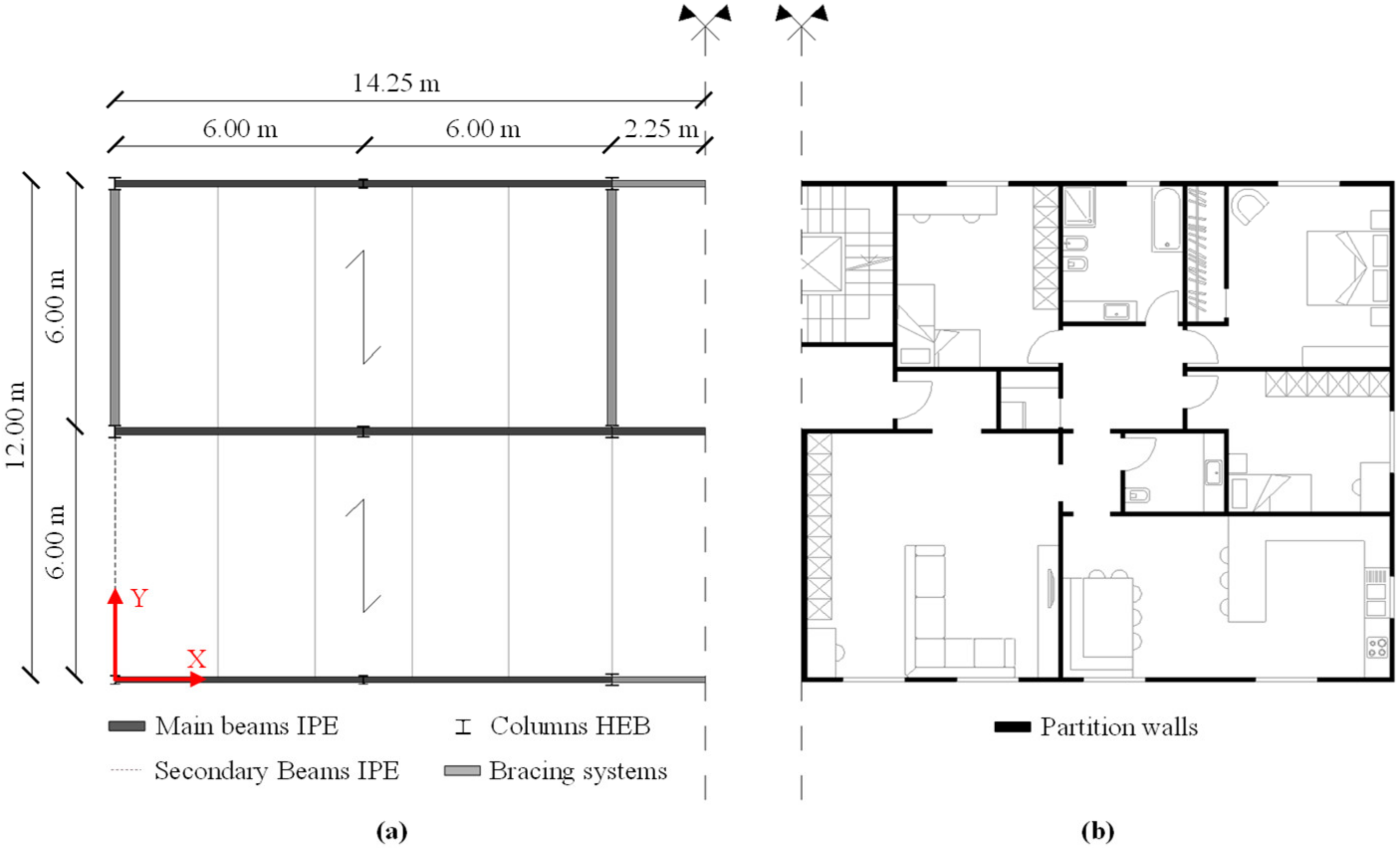
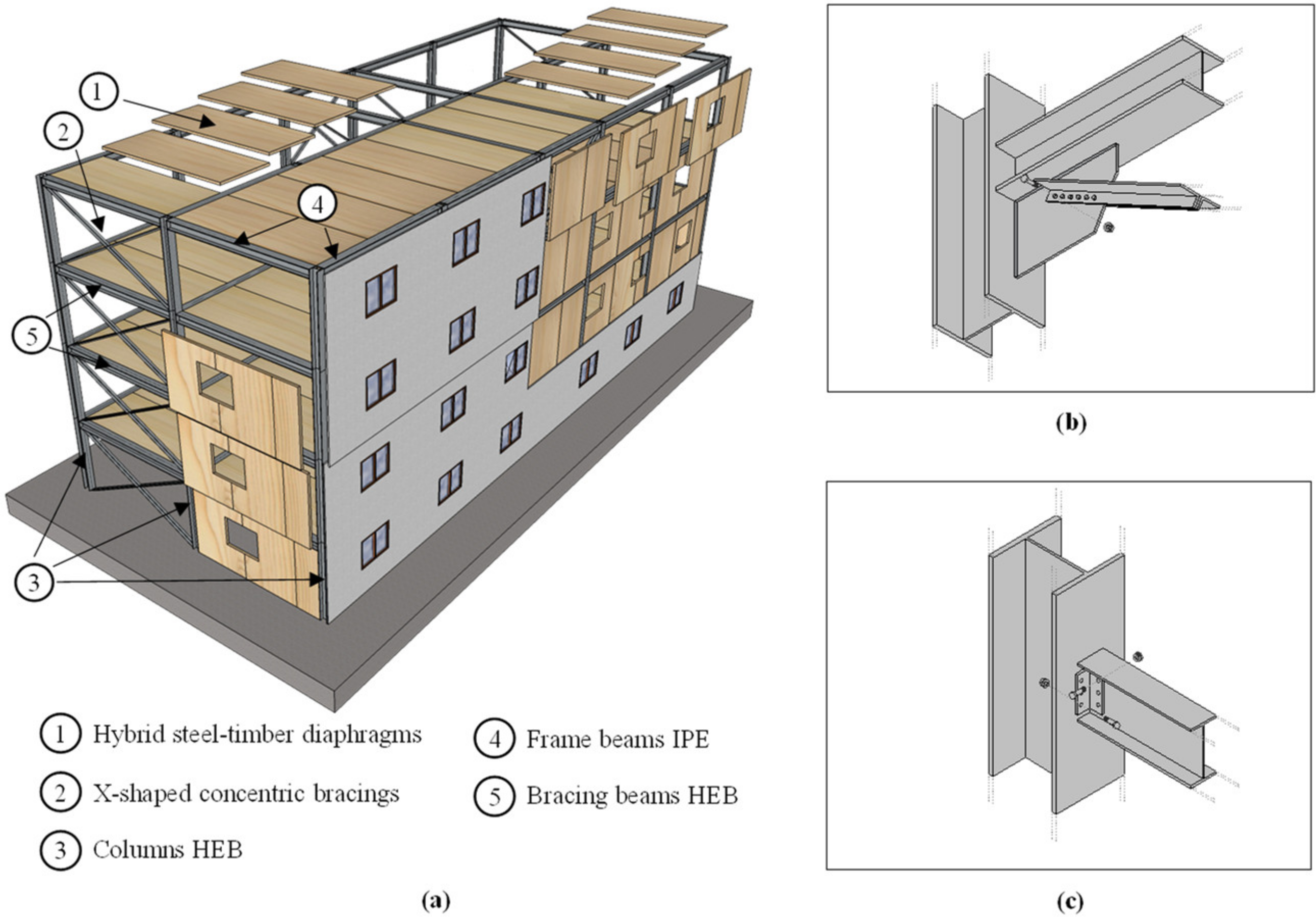
2. Building Description

2.1. Construction System

The building assessed by this research has a rectangular 28.5 m long by 12 m wide floor plan and comprises 3 stories (roof excluded) above the ground, for a total height of 12.8 m and a constant inter-story height of 3.2 m. The building’s architectural plan consists of eight 6 m by 6 m and two 4.5 m by 6 m grids. The columns’ layout guarantees a flexible distribution of the internal spaces with the possibility to fulfill different living needs and change the layout during the building’s lifespan, as can be seen in Figure 1a. Each story can accommodate two to four residential units based on the current market-rate rental apartment requirements and best practices, as can be seen in Figure 1b.
Underneath the building’s envelope lies a modular steel frame stabilized by four and two X-diagonal bracing systems along shorter and longer directions. This three-dimensional frame has main beams laid along the building’s long-side direction, while secondaries are arranged along the shortest direction. The building has 5 and 2 spans along the main (X) and secondary (Y) façade directions. Figure 2a shows that the external walls are finished by cross-laminated timber (CLT) panels infilled into the frame, and floors are assembled using hybrid CLT-steel modular prefabricated elements.
In contrast with CLT infilled reinforced Moment-Resisting (MR) steel frames, where CLT panels are used to enhance both lateral stiffness and strength of the building, the CLT walls do not perform a structural function in this building. Specifically, CLT panels are connected using light steel hardware to build a non-structural system that does not alter the deformation and load-carrying capacity of the LFRS.
Parallel flange I- and wide flange H-shaped hot-rolled profiles are used as columns and beams of the steel frame, whereas L-formed hot-rolled profiles form the concentric diagonals of the bracing systems. Each column’s cross-section is optimized to account for the effective acting load so that sizes decrease moving up to the building’s top floor. S275 and S355 strength classes are used for the steel profiles, with characteristic yield and ultimate strength in accordance with UNI EN 10025-2 [30]. Table 1 lists the cross-section and steel properties of the profiles.
Members and connections of the hybrid steel-timber construction assembly are designed to provide the building with stiffness and strength to satisfy ultimate limit state (ULS) and serviceability limit state (SLS) design requirements under gravity loads, and perform no-collapse (NC) and damage limitation (DL) under seismic loads, as per the Italian Building Code [31] and Eurocode 8 [29]. Details of the beam-to-column and bracing joints are given in Figure 2b,c, respectively. Specifically, the bracing systems’ vertical and horizontal elements are connected with welded steel plates and diagonals fastened using bolts. The bracing systems’ joints are sized adopting capacity design provisions of the Eurocode 8 [29] and ‘Norme Tecniche per le Costruzioni’ (NTC) [31]. The beam-to-column joints of frames are made using bolted steel brackets.

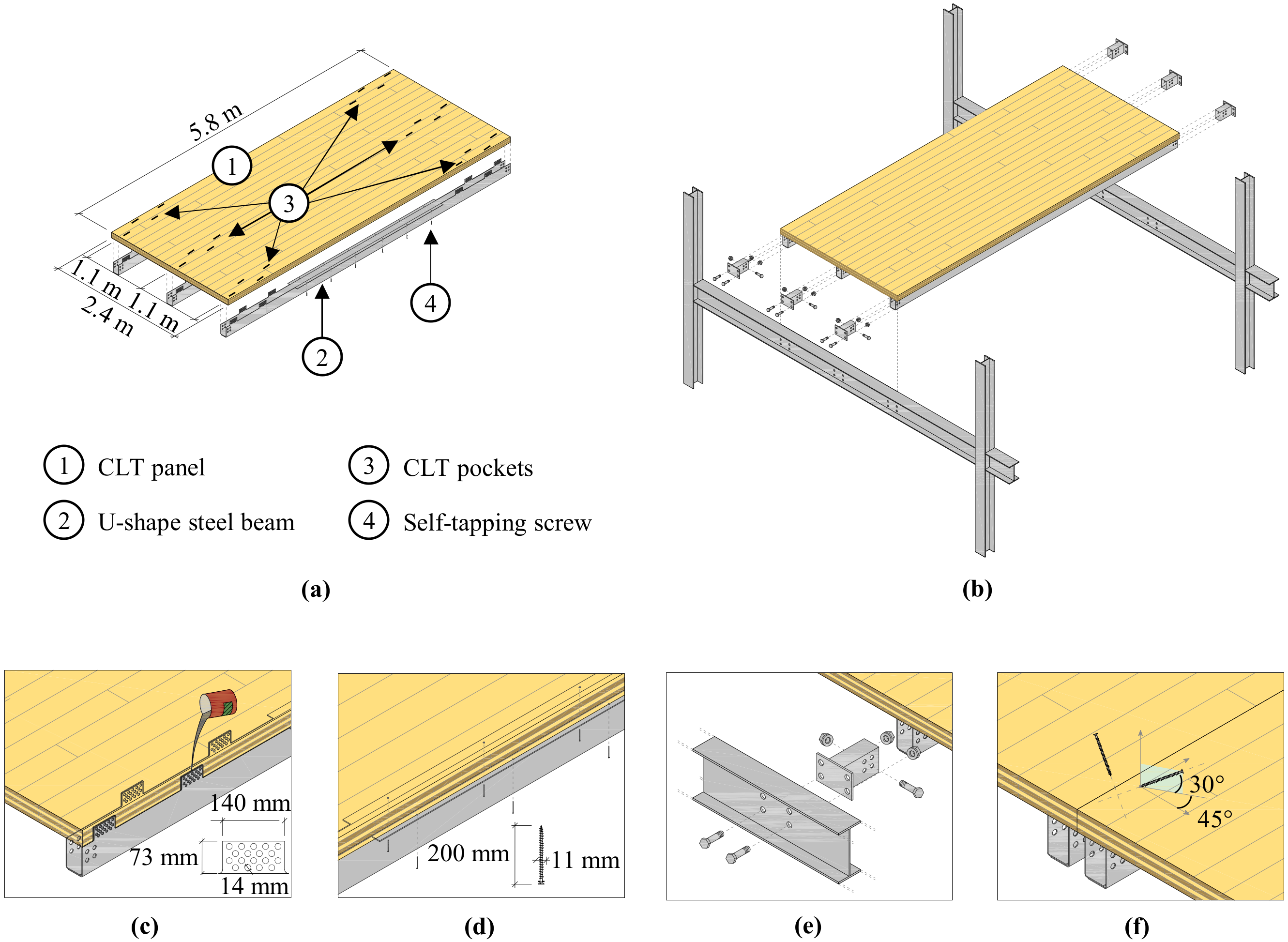
2.2. Innovative Composite CLT-Steel Prefabricated Floors

Floor construction technology is new and features highly industrialized—easy to fabricate—hybrid CLT-steel modular elements (Figure 3a).
Floors are mounted on-site by fastening each prefabricated CLT-steel modular unit to the primary beams, which in turn are bolted to the steel frame columns. Specifically, each floor unit is placed inside a repeatable grid of beams and then fixed using ad hoc shaped steel links, as shown in Figure 3b. The assembly process is completed by inserting self-tapping screws (STS) along the CLT panels’ edges and tightening the bolts up to a fixed preload. Floor elements are fabricated in such a way that shear forces generated under both in- and out-of-plane loads are transferred through steel-timber connections from the CLT panels to the steel cold-formed profiles.
The adoption of special steel links is beneficial for both design and construction purposes. In fact, design details and shape of the links are chosen based on the structural behavior that is wanted, especially the stiffness and strength capacity, for the floors. Besides, adopting a proper shape of the links can improve the erection and permit adjustment of their position to account for possible mounting imperfections. For the proposed solution, links consist of flanged short pipe elements with dimensions and tolerance that allow their insertion into the steel beams and then enable us to account for misalignments, squareness, or any out of plumb of the frames.
Concerning residential construction applications, this construction method is studied in Loss et al. [32] and [33]. Results from an experimental campaign on the bending behavior and in-plane shear response of those floors are presented in Loss and Davison [34] and Loss and Frangi [35], respectively. Loss et al. [36] and [37] give respectively optimum solutions for materials saving, especially thickness of steel elements and layered structure of CLT, and for maximizing shear transfer among CLT panel forming the slabs.
Figure 3c–f show construction details of the repeatable prefabricated modules considered for this study. A 2.4 m wide by 5.8 m long 5-ply C24 [38] CLT panel and three S355 [39] cold-formed U-shaped steel profiles placed in an equally spaced manner at mid and both edges panel form the floor composite section. Beams are manufactured to have 8 protruding perforated plates coming out at their extremities (Figure 3c) and 2 ledges (Figure 3d) in the middle. CLT panels are provided with pockets at their extremities to accommodate for the beam’s assembly. Steel beams are bounded to the CLT panels using an epoxy-based grout poured into the spaces between the steel punched plates and wood pockets and up to fill cavities pockets. Installation of the steel beams is completed by inserting 12 constant-spaced 6 mm diameter by 80 mm length self-tapping screws in the middle (Figure 3d). The composite CLT-steel elements are fastened to the mainframe using 8 M16 8.8-grade bolts [40], Figure 3e. Bolts are tightened with a 100 Nm preload. Afterwards, 11 mm diameter by 200 mm length crosswise inclined fully-threaded self-tapping screws are inserted at each side of the CLT slab of the nearby floor units, as seen in Figure 3f.

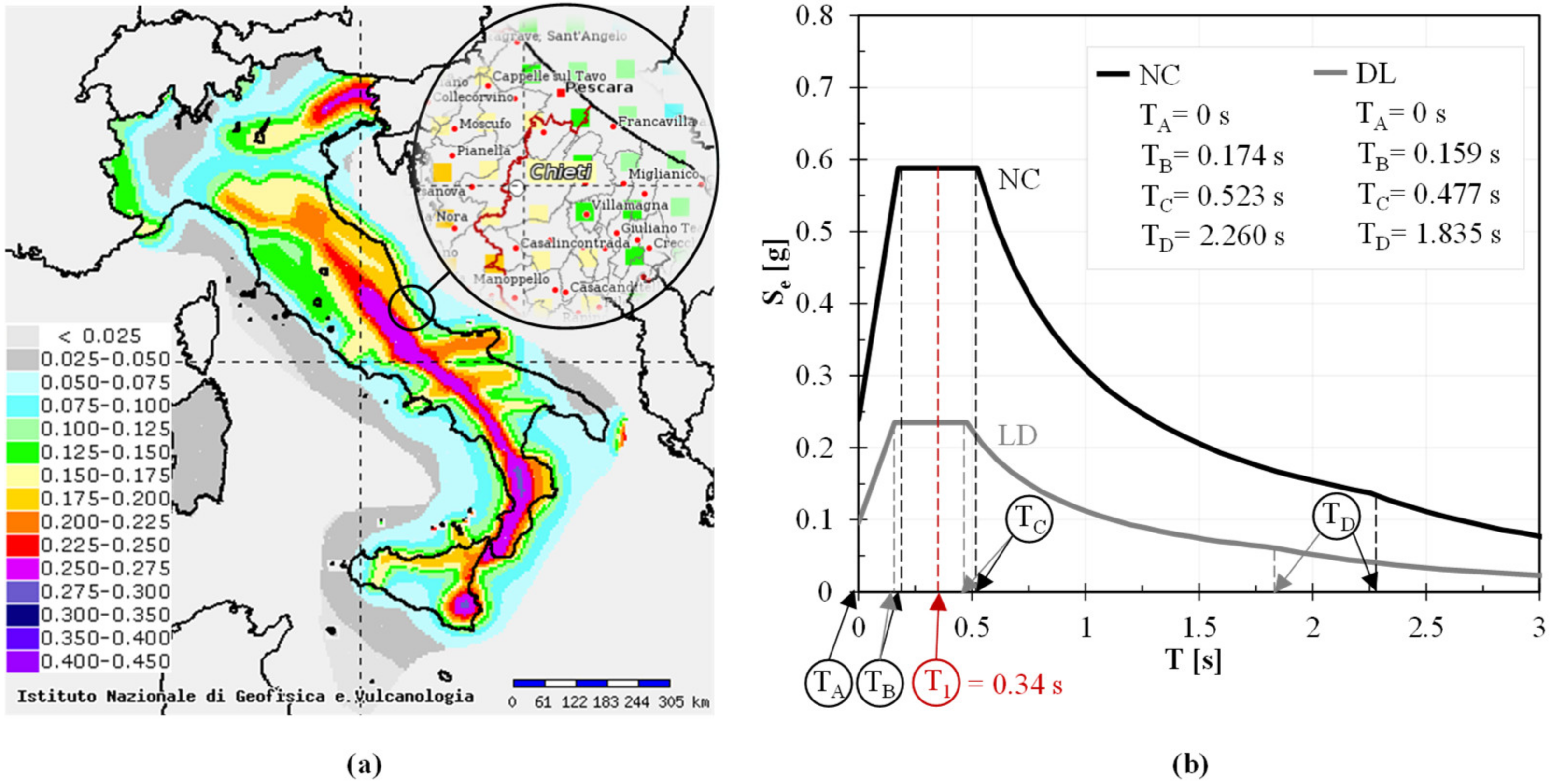
2.3. Design Loads and Combinations

The building is located in the middle of the Italian peninsula, in a town that was hit by the L’Aquila Earthquake in 2009 [41]. The area is characterized as a medium to high seismic hazard area following the new classification by Montaldo et al. [42]. Geographical coordinates 42.0334° N for latitude and 14.3792° E for longitude are used to calculate the influence of local hazard and ground conditions on the seismic action. Live loads (Q) of 2 kN/m2 are assumed for the gravity design and are those recommended by the Italian Building Code [31] for multi-story residential buildings. Dead load (G2) of nonstructural components is equal to 3 kN/m2 and does not include the self-weight (G1) of structural members. The load combination parameter for live loads Ψ2 is equal to 0.3.
The seismic design load is based on the seismic hazard map of Italy (Figure 4a) and the response acceleration spectra (Figure 4b), both detailed in the NTC [31].
Response spectra are set to a soil class type C, topographical category type ‘t1′, and a building’s lifespan of 50 years. The peak ground acceleration (agR) is equal to 1.62 m/s2 and 0.63 m/s2, respectively for the non-collapse (NC) and damage limitations (DL) design requirements. The soil amplification factor (F0) is assumed to be constant and be equal to 2.46.

2.4. Design Procedure and Ductility Capacity Requirements

Elements and connections have been designed for both gravity and seismic loads. Bracing systems also have been sized to withstand forces induced by global and local imperfections, accounting for standard on-site installation uncertainties as per steel building systems. The equivalent linear-static lateral-force procedure has been adopted assuming a fundamental period of vibration (T1) of 0.34 s for the building, calculated with the design formula provided in the Eurocode 8 [29] for ‘other’ types structures. The horizontal seismic design force Fi,d acting at each story (i-th) has been reported in Table 2, along with the calculated seismic mass (Wi) and height from the ground (Zi), and the base shear Vb.
Accidental torsional effects have been included in the sizing of the vertical LFRS elements following the procedure given in the Eurocode 8 [29].
The design has been executed assuming rigid diaphragms and considering structural assembly as a result of ductile members, which dissipate energy during the ground motion through their hysteretic behavior and non-dissipative members which remain elastic. Specifically, the design spectrum at NC limit state has been drawn adopting a behavior factor q of 4, to account for the capacity of the structure to dissipate energy through ductile mechanisms induced by the plastic deformation of the bracing systems.
As one of the common dissipative technologies covered by NTC [31], concentrically braced frames have been detailed so their braces plasticize and their beams and columns remain elastic. Sizes of bracings’ diagonals have been established based on the stress values obtained from the equivalent linear-elastic lateral-force analysis of the building, and considering the additional damage limitation verifications. Specifically, an inter-story drift of 0.5% has been assumed for the building under the seismic load derived starting from the DL response spectrum.
Design of the bracing systems reflected active tension diagonals only and accounted for the hole-bolt gaps, while compressed diagonals have been neglected as contributing to non-dissipative elastic elements. The non-dimensional slenderness λ of diagonals members, as defined in Eurocode 3 [43], has been kept between 1.3 and 2.0 in accordance with the Eurocode 8 [29] requirements. Cross-section sizes of steel diagonals chosen accordingly. To provide a building with a homogeneous dissipative behavior throughout its entire height, the sizing of diagonals has been executed in such a way that the effective over-strength capacity of diagonals results is always lower than 25%.
Beam-to-column and beam-to-column-brace joints have been detailed in respect of the capacity design method by following the simplified procedure and equations provided in the Italian Building Code [31] and Eurocode 8 [29]. Table 3 lists the geometry and properties of the bracing systems, including the number of bolts and the hole-bolt specifics.

3. Assessment of the Structural Response

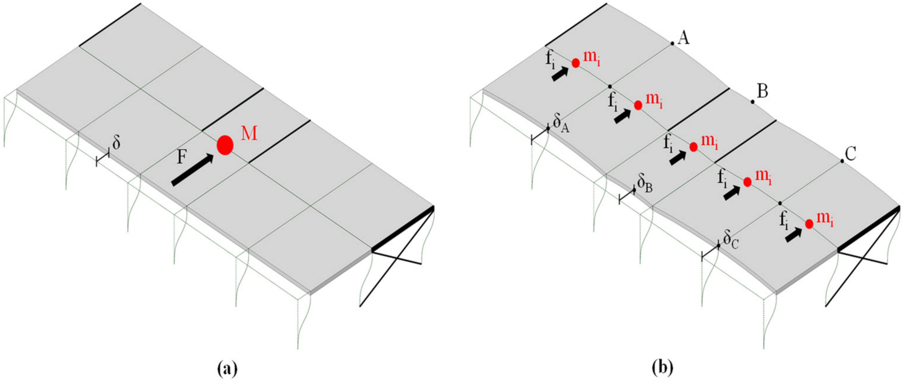
3.1. Non-Linear Static Structural Analyses

The structural assembly has been designed to meet in-plan and elevation regularity requirements as per the Italian Building Code [31] and Eurocode 8 [29]. Therefore, the building’s lateral response has been assumed to be governed by its fundamental mode of vibration and structural performance extracted through Non-Linear Static Analyses (NLSA). NLSA have been carried out using finite-elements software SAP2000 [44]. For comparison purposes, two different building models have been considered: Model I, accounting for effective in-plane stiffness of floor diaphragms, and Model II, assuming an ideal rigid body behavior of floor diaphragms, with the latter simulated with displacement-constrains among the lateral force resisting system (LFRS). Finite-Element (FE) models have been implemented simulating inelastic behavior through assigned plastic hinges at side-ends of LFRS members and within the floor’s subsystems. Furthermore, compression diagonals’ influence has been considered within the building’s elastic lateral response until buckling is reached.
Push-over lateral forces have been applied following two distinct vertical distributions as per Eurocode 8 provisions: a ‘modal’ Load Pattern (LP)—a and a ‘uniform’ Load Pattern (LP)—b. Under the Eurocode 8 simplified procedure for rigid floor diaphragms, lateral forces have been applied at the center of gravity on each Model II floor. Instead, an equivalent lateral distributed load has been applied along the CLT panels edges at each story of Model I. On the one hand, with such lateral forces’ distribution, the Model I’s local deformability when applying concentrated forces has been avoided; on the other, the global deformability of each floor diaphragm on average has been considered. The initial equilibrium state and elastic deformation of models accounted for gravity loads based on the load combination previously described. The X- and Y-direction of the building have been studied separately. The results have been reported exclusively for the Y-direction, while considering that the building has two bracing systems in the X-direction.
Though NLSA, the building’s structural performance has been numerically simulated considering control point at the top floor and stopping analyses upon ultimate load reached, herein conventionally defined as 80% of the maximum load after the peak. Displacement, ductility, stiffness, drift, and strength capacity values have been assessed accordingly.

3.2. FE-Model

The as-built FE-Model, FE-sub-models of bracing systems and floors have been reported in Figure 5a–c. Columns, beams and X-diagonals have been modeled using linear elastic elements. Through zero-length hinges with moment-rotation and force-displacement model attributes, a concentrated plasticity approach has been used to account for inelastic deformation of the members: 192 were distributed on the bracings, 144 were on the columns, and 48 were on the beams, for a total of 384 plastic hinges located at their ends. Thick shell elements have been used for modeling the CLT panels. To simulate the response of the floor’s connections and joints and beams, combinations of frame, spring, and gap FE-model elements either in parallel or series, as well as 4392 plastic hinges, have been implemented. Elastic-brittle and elastic-plastic strength-deformation relationships have been used for wood and steel, respectively.
With reference to the bracing systems of Figure 5b, specific inelastic hinge parameters and model attributes have been provided in Figure 5d–f, respectively.
X-diagonals concentric bracings have been modeled using isotropic P-type hinges activated under tension loads and a buckling function for accounting for structural instability when under compression. Buckling force values, displacement, and other parameters of the force-displacement asymmetric curve of Figure 5d have been derived following FEMA-356 [45] procedure. Columns have been modeled through isotropic P-M2-M3-type hinges to account for the reduction of moment-rotation plasticity induced by compression force, as shown in Figure 5e. Accordingly, P-M3-type hinges have been considered for the beams, as depicted in Figure 5f. Column and beam moment-rotation relationships have been derived based on FEMA-356 [45] instructions for steel braced frames. Moreover, spring elements have been used to simulate the hole-bolt gaps (Figure 5i).
FE-implementation of floors has been based on behavior observations by using experimental tests and data recorded by Loss and Frangi [35]. With reference to Figure 5c, linear elastic orthotropic shell elements have been used for modeling the CLT panels. Steel profiles have been modeled using frame elements with two different cross-section profiles instead. The individual FE-elements’ behavior of connections and joints have been provided in Figure 5g–n. Specifically, the beam-to-frame joints have been modeled combining 3 elements in series: a frame element to account for the steel plate bolted on the main beam (element 1), a spring element for the beam-to-beam contact surface and friction (element 2), and another spring element for the gap between the hole and bolt (elements 3). Force-displacement relationships have been included in Figure 5g–i for elements 1 to 3, respectively. Connections between CLT panel and secondary beam used frame elements with M2-type hinges have been calibrated from the experimental dataset mentioned earlier. Specifically, the non-linear load-slip curve recorded from the experiments presented in Loss et al. [32,33] has been transformed into a moment-rotation capacity curve and related yield, maximum and ultimate values derived accordingly. The moment-rotation calibrated curve has been provided in Figure 5n. CLT panel-to-panel connections have been modeled as a combination of frame elements and plastic hinges, with mechanical properties calibrated using the experimental tests. The same approach discussed above has been adopted with transformation of the experimental recorded load-slip curve [32,33] into a moment-rotation curve to be used in the FE model. The moment-rotation calibrated curve has been provided in Figure 5m. Gap elements have been inserted to prevent overlapping of materials and related force-displacement curve included in Figure 5.

3.3. Structural Performance Parameters

Load-displacement (F-Δ) curves drawn from the NLSA have been used to derive the building’s structural performance parameters, such as displacement ductility, lateral elastic stiffness, and respectively yield, maximum, and ultimate loads. The yielding point has been assumed when the first plastic hinge develops on the FE-model. The ultimate state has been conventionally defined when load equals 80% of its maximum after the peak has reached. Lateral elastic stiffness ki has been calculated as the ratio between the yield load Fy and yield displacement Δy, while ductility μΔ was obtained as the ratio between ultimate displacement Δu and the yield displacement Δy. Maximum load FM and ultimate load Fu has been defined as the peak load extracted from the F-Δ curves, whereas Fu has been defined as 80% of FM.
Under DL limit state loading, the lateral deformation induced by in-plane stiffness of floors has been assessed by comparing horizontal displacements of Models I and II. On the other hand, the alteration of lateral load transmission into bracing systems induced by diaphragms deformability has been detected under NC limit state loading. The shear forces ratios at each story have been provided explicitly for internal bracings only (Br,i), considering that the building is symmetric and has 4 bracing systems regularly distributed in the floor plan. Specifically, such ratios have been assessed based on shear forces extracted from Model I and Model II. The displacement at each story δ (Figure 6a) has been derived in average value among maximum displacement of the floor measured in each bay (δA, δB and δC of Figure 6b).
Inter-story drift θ calculated as the ratio between relative translational displacement and relative height between two consecutive floors. The fundamental period of the building T1 in the main horizontal direction of loading has been assessed through modal elastic analysis.

4. Results and Discussion

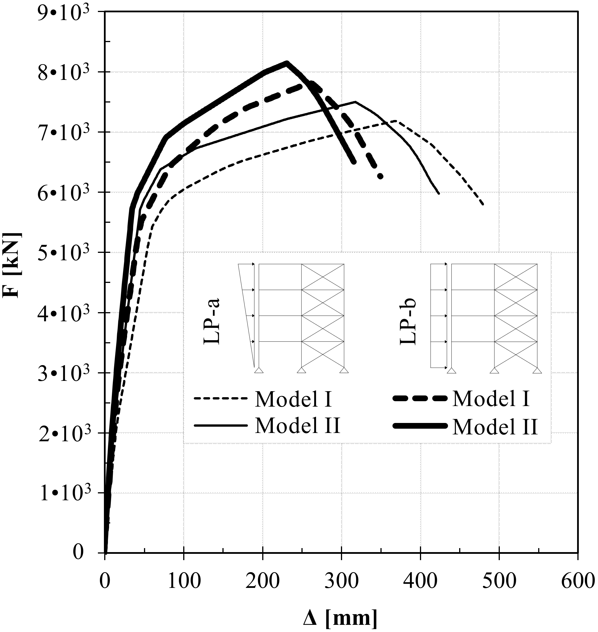
4.1. Load-Displacement Curves

An overview of the building’s nonlinear static lateral response under seismic loads is given in Figure 7, where 4 different capacity curves are illustrated based on two load patterns, modal distribution (LP-a fine lines), and uniform distribution (LP-b thick line), and considering ideal rigid (Model II continuous lines) or deformable floor diaphragms (Models I dashed lines), respectively. Moreover, stiffness, ductility, and yield, maximum and ultimate displacements, corresponding loads, along with the fundamental periods assessed for the building, are provided in Table 4.
Whether under LP-a or LP-b, load-displacement curves suffer a comparable shift of both yield and ultimate displacements and the loss of the peak load, when assuming actual in-plane stiffness of diaphragms instead of their rigid behavior. In general, the diaphragm’s flexibility further leads to a reduction of lateral stiffness and effective ductility capacity of the building. As a counterpart, it increases its fundamental period, as shown in Table 4. With LP-a, results indicate that the building’s stiffness reduces by 27.5%, while the fundamental period (T1) goes up by 9.7%. Accordingly, the ductility reduces by 9.7%. No less significant is scenario LP-b, having stiffness and ductility reduced by 24.2% and 7.5%, respectively. T1 jumps up by 9.7%, accordingly. The flexibility brought in with non-rigid diaphragms reduces the yield strength of 8.9% on average. Lowering lateral-force capacity is observed on both LP-a and LP-b, with a maximum force reduction value of 4.2% and 4.1%, respectively.
The different shape of the load-displacement curves of Figure 7 is mostly driven by two ductile structural mechanisms of deformation, each which differs for the effective displacement capacity at the ultimate state (herein 80% FM), and even more for the distribution of plasticity throughout the bracing ductile members. As a matter of fact, at peak load with LP-a, 72% of plastic hinges develop at all levels of the building when rigid floor diaphragms are assumed. In comparison, with LP-b, only 65% of plastic hinges are formed and are mostly located among the first story’s vertical LFRS elements. Accordingly, at peak load with LP-a, 66% of plastic hinges develop at all building levels when in-plane stiffness of floor diaphragms is accounted for. In comparison, with LP-b, only 61% of plastic hinges are formed and are mostly located among the first story’s vertical LFRS elements. Observing the loss of ductility and reduction of energy dissipation capacity, the latter indirectly assessed through the number of formed plastic hinges, results show needs for adjustment in the force reduction factor. As a matter of fact, a reduction is expected in the building’s dissipation capacity. Eurocode 8 [29] design formula for assessing the building’s fundamental period also requires revision to include reduction of stiffness brought in by non-rigid floor diaphragms.

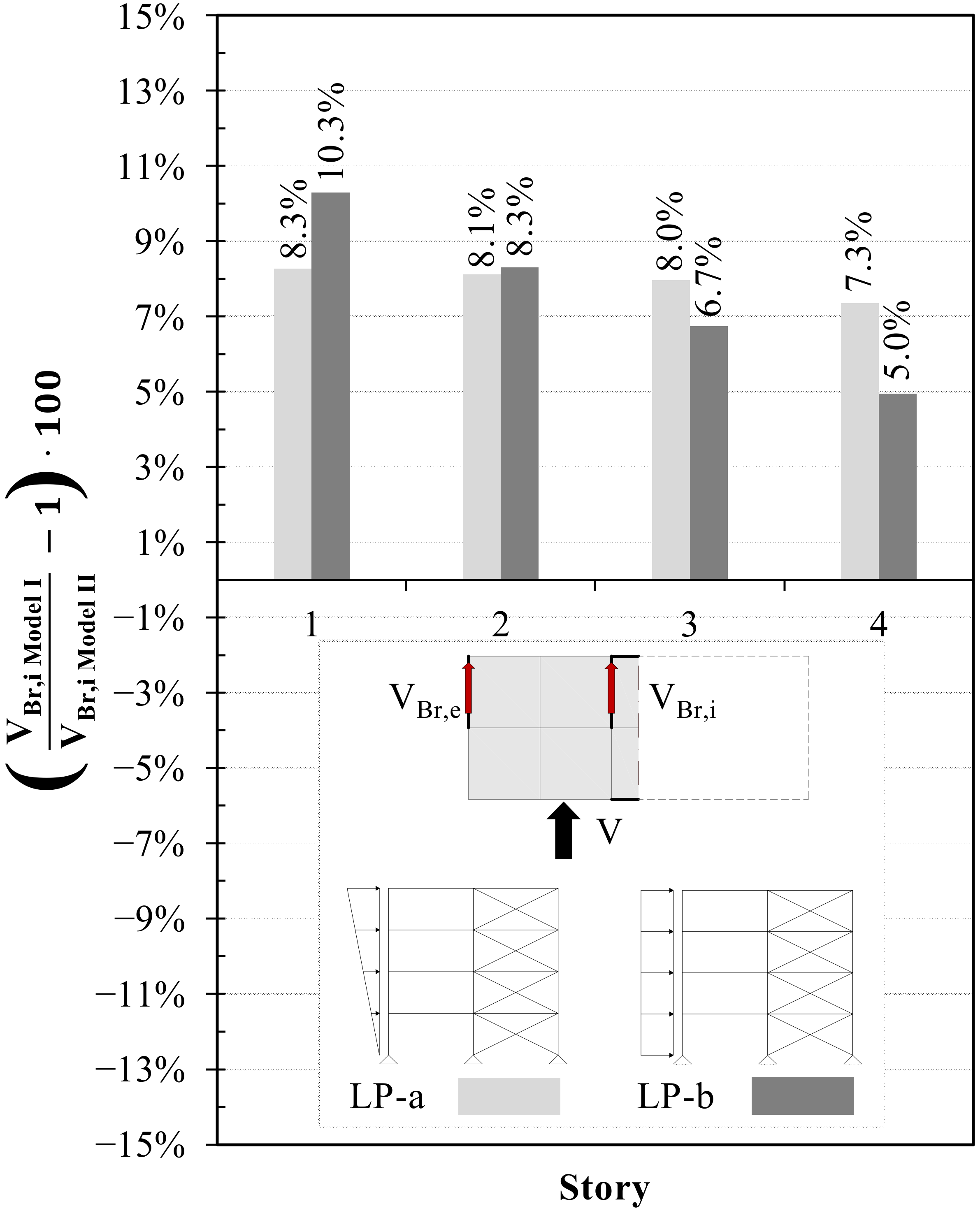
4.2. Shear Forces Ratios

Figure 8 provides charts of shear forces ratios in the building’s bracing systems (compared with the rigid floor design) for the LP-a, modal distribution, and LP-b, uniform distribution, respectively, at each story, roof level included. The actual values of shear force ratios are also given in Figure 8. Such forces are assessed assuming the NC design load (FNC = 1199.4 kN) as the acting load on the building. With the building’s symmetry in both plan and elevation and regular layout of the bracing systems, charts of Figure 8 only give shear forces ratios of the internal bracings. Shear forces of the external bracings are equivalent in absolute values but with a reversed sign.
Floor diaphragms acting as a rigid body behave in such a way that their sub-components translate and rotate with the same amplitude, independently of the loading direction. Transfer of story shear force to the vertical LFRS elements depends on their stiffness and locations. When the rigid response is not guaranteed, the distribution of story shear force also depends on the actual in-plane stiffness of floor diaphragms, the spacing and arrangements of the vertical LFRS elements, and the aspect ratio and dimensions of floors.
Independently of the LP, Model II leads to having the same amount of shear forces at each story of the building into the vertical LFRS elements. Therefore, column charts of Figure 8 show the ratios of the shear forces referred to the rigid body behavior (Model II), and assume NC limit state load is applied to the building (FNC = 1199.4 kN). Generally speaking, under LP-a, the force demand in the bracing elements is comparable throughout the height of the building, as confirmed by the range between 7.3% to 8.3% of the shear forces ratios depicted in Figure 8. Conversely, LP-b conduces having higher force demand into the building’s lowest stories and so that higher difference in terms of shear forces ratios from top story to the downstairs, with values between 5.0% to 10.3% of the shear forces ratios.

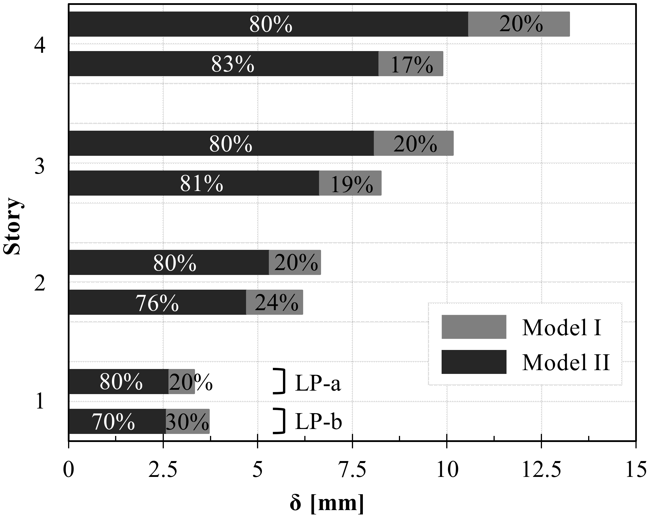
4.3. Lateral Deflection

Under LP-a, modal distribution, and LP-b, uniform distribution, respectively, the building’s maximum lateral displacements at each story are displayed in Figure 9. Displacements are referred herein to the DL limit state of the building and are taken at the center of gravity of each story, as the average of deformation in each bay of floors. Table 5 also lists the lateral displacement values and the relative inter-story drifts, with the latter calculated as differences of lateral displacements between two consecutive floors, and expressed as a percentage based on the matching inter-story height. Charts of Figure 9 also provide the percentage of maximum lateral deformation given by the in-plane flexibility of bracings (white marks) and floors (black marks) of Model I only.
Under DL limit state load, building’s lateral response depicted in Figure 9 shows an increment of the absolute value of displacement at each story induced by diaphragms’ flexibility. Independently of the LP, the in-plane flexibility of floor diaphragms always leads to an increase of lateral displacement of at least 17%, and an average increase of 21%. Regarding the inter-story drift listed in Table 5, the maximum recorded value equals 0.12% and is taken at the 1st floor under LP-b. Such value complies with NTC’s [31] requirements, being lower than the 0.5% drift limit. Under LP-a, by comparison of Models I and II, results show a clear shift of θ induced by the in-plane stiffness of diaphragms with a uniform increment of 24.9% on average.
With the alteration of lateral maximum displacement, δDL, difference between Models I and II always higher than 10%, and independently of the LP and the story level considered, the CLT-steel hybrid floor technology herein studied does not meet Eurocode 8 minimum design requirements for ‘rigid’ diaphragms. Eventually, the DL limit state design requires deformability of the diaphragms to be included in such a way the simplified procedure is still applicable. Research is needed to incorporate correction factors into such a procedure while considering effective floors’ in-plane behavior, or including design details to provide floors with their rigid behavior when applicable.

5. Conclusions

Through nonlinear static analyses, the seismic response of a multi-story cross-laminated timber (CLT)-steel-based hybrid building has been assessed. Specifically, the influence of the in-plane stiffness of hybrid CLT floor diaphragms on the lateral building deflection and shear load distribution among the lateral force-resisting elements has been investigated. It has been possible to conclude that:
  • The actual in-plane stiffness of floor diaphragms induces a reduction of the lateral building’s stiffness (ki) between 24.2% and 27.5% compared to ideal rigid floor diaphragms.
  • Even with symmetric arrangements and moderate spacing of bracing systems, and limited building’s height, in-plan deformability of floor diaphragms leads to an increase of the shear forces (VBr,i) into their members up to 10.3%.
  • The influence of the actual in-plane stiffness of floors on the lateral deformation (δDL) is higher compared to stress-induced deformation on the bracing elements (VBr,i NC), suggesting that the damage-limitation (DL) limit state is more sensitive than the non-collapse (NC) limit state design condition.
  • Results encourage the adoption of two correction factors for a tuning simplified seismic design procedure. One factor is recommended to adjust design shear forces of shear walls compare to the ideal case of rigid floors, the second factor is recommended instead to account for the increase of lateral deflection in the evaluation of the inter-story drift and global lateral displacement of buildings.
  • Above the holistic Eurocode 8′s approach for rigid diaphragms, research for specific design provisions is needed to address sizing of elements that is different from the traditional wooden floor systems.
  • The numerical approach based on an experimentally validated model has the potential for studying other hybrid floor systems or different buildings’ lateral force-resisting systems, or for further carrying out non-linear dynamic analyses.
  • A second-stage of study is required to further assess the influence of the arrangement of the bracing systems and the shape and dimensions of floors and vertical lateral force-resisting system (LFRS) elements on the load distribution. In addition, the dynamic behavior of buildings needs to be investigated.

Author Contributions

F.G. developed and validated the FE-model and performed the first stage of numerical analyses. A.R. completed execution of numerical analyses and processed the dataset. Original draft of the paper was also written by A.R. C.L. supervised the research and was responsible for the funding acquisition. C.L. also provided background information and editorial review of the manuscript. All authors participated in finalizing the article. All authors have read and agreed to the published version of the manuscript.

Funding

This research was funded by Natural Sciences and Engineering Research Council (NSERC) of Canada through the Discover Program, grant number RGPIN-2019-04530, and Discovery Launch Supplement, grant number DGECR-2019-00265. Financial support from the University of Trento, through the ‘international mobility for research abroad’ scholarship granted to Andrea Roncari, is gratefully acknowledged.

Institutional Review Board Statement

Not applicable.

Informed Consent Statement

Not applicable.

Data Availability Statement

No ethical, legal or privacy issues have been detected within this publication.

Conflicts of Interest

The authors declare that the research was conducted in the absence of any commercial or financial relationships that could be construed as a potential conflict of interest.

References

  1. Ramage, M.H.; Burridge, H.; Busse-Wicher, M.; Fereday, G.; Reynolds, T.; Shah, D.U.; Wu, G.; Yu, L.; Fleming, P.; Tingley, D.D.; et al. The wood from the trees: The use of timber in construction. Renew. Sustain. Energy Rev. 2017, 68, 333–359. [Google Scholar] [CrossRef]
  2. Dodoo, A.; Gustavsson, L.; Sathre, R. Lifecycle carbon implications of conventional and low-energy multi-storey timber building systems. Energy Build. 2014, 82, 194–210. [Google Scholar] [CrossRef]
  3. Werner, F.; Richter, K. Wooden Building Products in Comparative LCA-A Literature Review. Int. J. Life Cycle Assess. 2007, 12, 470–479. [Google Scholar]
  4. Hough, R. Rethinking Timber Buildings Seven Perspectives on the Use of Timber in Building Design and Construction, 1st ed.; ARUP: London, UK, 2019. [Google Scholar]
  5. Karacabeyli, E.; Gagnon, S. Canadian CLT Handbook SP-532E; FPInnovation: Montreal, QC, Canada, 2019. [Google Scholar]
  6. Smith, I.; Frangi, A. Use of Timber in Tall Multi-Storey Buildings, 1st ed.; International Association for Bridge and Structural Engineering (IABSE): Zürich, Switzerland, 2014. [Google Scholar]
  7. Schuirmann, A.; Loss, C.; Iqbal, A.; Tannert, T. Structural and environmental analyses of tall wood-concrete hybrid system. In Proceedings of the CSCE 2019 International Specialty Conference on Engineering Mechanics and Materials, Laval, QC, Canada, 12–15 June 2019. [Google Scholar]
  8. Connolly, T.; Loss, C.; Iqbal, A.; Tannert, T. Feasibility Study of Mass-Timber Cores for the UBC Tall Wood Building. Buildings 2018, 8, 98. [Google Scholar] [CrossRef] [Green Version]
  9. Tesfamariam, S.; Stiemer, S.F. Special issue on performance of timber and hybrid structures. J. Perform. Constr. Fac. 2014, 28, A2014001. [Google Scholar] [CrossRef]
  10. Fragiacomo, M.; van de Lindt, J.W. Special issue on seismic resistant timber structures. J. Struct. Eng. 2016, 142, E2016001. [Google Scholar] [CrossRef]
  11. Pampanin, S. Towards the “Ultimate Earthquake-Proof” Building: Development of an Integrated Low-Damage System. In Perspectives on European Earthquake Engineering and Seismology. Geotechnical, Geological and Earthquake Engineering; Springer: Cham, Switzerland, 2015; Volume 39, pp. 321–358. [Google Scholar]
  12. Iqbal, A.; Pampanin, S.; Buchanan, A.H. Seismic Performance of Full-Scale Post-Tensioned Timber Beam-Column Connections. J. Earthq. Eng. 2016, 20, 383–405. [Google Scholar] [CrossRef]
  13. Ganey, R.; Berman, J.; Akbas, T.; Loftus, S.; Dolan, J.D.; Sause, R.; Ricles, J.; Pei, S.; van de Lindt, J.; Blomgren, H.E. Experimental Investigation of Self-Centering Cross-Laminated Timber Walls. J. Struct. Eng. 2017, 143, 04017135. [Google Scholar] [CrossRef]
  14. Green, M. The Case for Tall Wood Buildings, 2nd ed.; Michael Green Architecture: Vancouver, BC, Canada, 2018. [Google Scholar]
  15. Skidmore, L.; Owings, N.; Merrill, J.O. Timber Tower Research Project: Final Report; SOM: Chicago, IL, USA, 2013. [Google Scholar]
  16. Skidmore, L.; Owings, N.; Merrill, J.O. AISC Steel & Timber Research for High-Rise Residential Buildings: Final Report; SOM: Chicago, IL, USA, 2017. [Google Scholar]
  17. Hassanieh, A.; Valipour, H.R.; Bradford, M.A. Experimental and numerical study of steel-timber composite (STC) beams. J. Constr. Steel Res. 2016, 122, 367–378. [Google Scholar] [CrossRef]
  18. Hassanieh, A.; Valipour, H.R.; Bradford, M.A. Experimental and numerical investigation of short-term behaviour of CLT-steel composite beams. Eng. Struct. 2017, 144, 43–57. [Google Scholar] [CrossRef]
  19. Winter, W.; Tavoussi, K.; Parada, F.R.; Bradley, A. Timber-Steel Hybrid Beams for Multi-Storey Buildings: Final Report. In Proceedings of the World Conference on Timber Engineering (WCTE), Vienna, Austria, 22–25 August 2016. [Google Scholar]
  20. Wu, Y.; Xiao, Y. Steel and glubam hybrid space truss. Eng. Struct. 2018, 171, 140–153. [Google Scholar] [CrossRef]
  21. Tesfamariam, S.; Stiemer, S.F.; Dickof, C.; Bezabeh, M.A. Seismic Vulnerability Assessment of Hybrid Steel-Timber Structure: Steel Moment Resisting Frames with CLT Infill. J. Earthq. Eng. 2014, 18, 929–944. [Google Scholar] [CrossRef]
  22. Li, Z.; He, M.; Wang, X.; Li, M. Seismic performance assessment of steel frame infilled with prefabricated wood shear walls. J. Constr. Steel Res. 2018, 140, 62–73. [Google Scholar] [CrossRef]
  23. Zhang, X.; Fairhurst, M.; Tannert, T. Ductility Estimation for a Novel Timber-Steel Hybrid System. J. Struct. Eng. 2016, 142, E4015001. [Google Scholar] [CrossRef] [Green Version]
  24. Asiz, A.; Smith, I. Connection system of massive timber elements used in horizontal slabs of hybrid tall buildings. J. Struct. Eng. 2011, 137, 1390–1393. [Google Scholar] [CrossRef]
  25. Sadashiva, V.K.; MacRae, G.A.; Deam, B.L.; Spooner, M.S. Quantifying the seismic response of structures with flexible diaphragms. Earthq. Eng. Struct. Dyn. 2012, 41, 1365–1389. [Google Scholar] [CrossRef]
  26. Colunga, A.T.; Abrams, D.P. Seismic Behaviour of Structures with Flexible Diaphragms. J. Struct. Eng. 1996, 122, 439–445. [Google Scholar] [CrossRef]
  27. Fleischman, R.B.; Farrow, K.T.; Eastman, K. Seismic Performance of Perimeter Lateral-System Structures with Highly Flexible Diaphragms. Earthq. Spectra 2002, 18, 251–286. [Google Scholar] [CrossRef]
  28. American Society of Civil Engineers (ASCE). Minimum Design Loads for Buildings and Other Structures; ASCE/SEI 7-10 Standard; American Society of Civil Engineers: Reston, VA, USA, 2010. [Google Scholar]
  29. European Committee for Standardization (CEN). EN 1998-1: Eurocode 8-Design of Structures for Earthquake Resistance. Part 1: General Rules, Seismic Actions and Rules for Buildings; CEN: Brussels, Belgium, December 2004. [Google Scholar]
  30. Ente Italiano di Normazione. UNI EN 10025-2: Prodotti Laminati a Caldo di Acciai per Impieghi Strutturali. Parte 2: Condizioni Tecniche di Fornitura di Acciai non Legati per Impieghi Strutturali; Ente Italiano di Normazione: Milan, Italy, April 2005. (In Italian) [Google Scholar]
  31. Italian Ministry of Infrastructures and Transport. NTC 2008: Norme Tecniche per le Costruzioni; Gazzetta Ufficiale Serie Generale: Rome, Italy, January 2008. (In Italian) [Google Scholar]
  32. Loss, C.; Piazza, M.; Zandonini, R. Connections for steel-timber hybrid prefabricated buildings. Part I: Experimental tests. Constr. Build. Mater. 2016, 122, 781–795. [Google Scholar] [CrossRef]
  33. Loss, C.; Piazza, M.; Zandonini, R. Connections for steel-timber hybrid prefabricated buildings. Part II: Innovative modular structures. Constr. Build. Mater. 2016, 122, 796–808. [Google Scholar] [CrossRef]
  34. Loss, C.; Davison, B. Innovative composite steel-timber floors with prefabricated modular components. Eng. Struct. 2017, 132, 695–713. [Google Scholar] [CrossRef]
  35. Loss, C.; Frangi, A. Experimental investigation on in-plane stiffness and strength of innovative steel-timber hybrid floor diaphragms. Eng. Struct. 2017, 138, 229–244. [Google Scholar] [CrossRef]
  36. Loss, C.; Hossain, A.; Tannert, T. Simple cross-laminated timber shear connections with spatially arranged screws. Eng. Struct. 2018, 173, 340–356. [Google Scholar] [CrossRef]
  37. Loss, C.; Rossi, S.; Tannert, T. In-plane stiffness of hybrid steel-cross-laminated timber floor diaphragms. J. Struct. Eng. 2018, 144, 04018128. [Google Scholar] [CrossRef]
  38. European Committee for Standardization (CEN). EN 338: Structural Timber-Strength Classes; CEN: Brussels, Belgium, October 2009. [Google Scholar]
  39. European Committee for Standardization (CEN). EN 10025-1: Hot Rolled Products of Structural Steels. Part 1: General Technical Delivery Conditions; CEN: Brussels, Belgium, November 2004. [Google Scholar]
  40. Ente Italiano di Normazione. UNI EN ISO 898-1: Caratteristiche Meccaniche Degli Elementi di Collegamento di Acciaio; Viti e viti prigioniere; Ente Italiano di Normazione: Milan, Italy, May 2001. (In Italian) [Google Scholar]
  41. Chiarabba, C.; Amato, A.; Anselmi, M.; Baccheschi, P.; Bianchi, I.; Cattaneo, M.; Cecere, G.; Chiaraluce, L.; Ciaccio, M.G.; De Gori, P.; et al. The 2009 L’Aquila (central Italy) MW6.3 earthquake: Main shock and aftershocks. Geophys. Res. Lett. 2009, 36, L18308. [Google Scholar] [CrossRef] [Green Version]
  42. Montaldo, V.; Meletti, C.; Martinelli, F.; Stucchi, M.; Locati, M. On-Line Seismic Hazard Data for the New Italian Building Code. J. Earthq. Eng. 2007, 11, 119–132. [Google Scholar] [CrossRef]
  43. European Committee for Standardization (CEN). EN 1993-1-1: Eurocode 3-Design of Steel Structures. Part 1-1: General Rules and Rules for Buildings; CEN: Brussels, Belgium, April 2004. [Google Scholar]
  44. Computers & Structures INC. Structural and Earthquake Engineering Software. CSI Analysis Reference Manual; Computers & Structures INC (CSI): Berkeley, CA, USA, 2016. [Google Scholar]
  45. Federal Emergency Management Agency (FEMA). FEMA 356: Prestandard and Commentary for the Seismic Rehabilitation of Buildings; FEMA: Washington, DC, USA, 2000. [Google Scholar]
Figure 1. Structure arrangement (a) and apartments’ layout (b).
Buildings 11 00009 g001
Figure 2. Building construction model (a); Bracing joints (b); Beam-to-column joints (c).
Buildings 11 00009 g002
Figure 3. Prefabricated floor units (a); Dry assembly of floor units (b); Joints overview: CLT-to-beam steel-timber connections (c,d), Beam-to-beam steel connections (e), and CLT-to-CLT timber connections (f).
Buildings 11 00009 g003
Figure 4. Seismic hazard map of Italy at 10% probability of exceedance in 50 years (a); Elastic Response Spectra (b).
Buildings 11 00009 g004
Figure 5. As-built Finite Element (FE) Model (a); FE subcomponents of bracing systems (b) and floor diaphragms (c); Model properties of specific FE elements: bracing system (d); bracing column (e); bracing beam (f); plate element (g); joint (h); hole-bolt element (i); connection frame element (l); screw element (m); resin plate element (n).
Buildings 11 00009 g005
Figure 6. Lateral maximum displacement (δ): average value (a) and individual recorded in each bay (b).
Buildings 11 00009 g006
Figure 7. Building capacity curves for LP-a and LP-b.
Buildings 11 00009 g007
Figure 8. Shear forces distribution under a NC design load for LP-a and LP-b.
Buildings 11 00009 g008
Figure 9. Building’s lateral maximum displacement under DL limit state loading for LP-a and LP-b.
Buildings 11 00009 g009
Table 1. Structural assembly cross section sizes.
ElementsProfileSteelCross-Sectional Area
(mm2)
BeamsIPE 360S3557270
IPE 300S3555380
IPE 220S2753340
HEB 220S2759100
ColumnsHEB 300S27514,910
HEB 280S27513,140
HEB 220S2759100
Table 2. Seismic force for each floor under non-collapse (NC) limit state loading.
StoryZiWiFi d
(m)(kN s2/m)(kN)
4 (roof)12.8206.6420.3
39.6255.9389.6
26.4255.9259.7
13.2255.9129.9
972.81199.4 1
1 Equivalent to base shear Vb.
Table 3. Steel bracing profiles.
StoryProfileSteelAreaBoltGap
(mm2) (mm)
42 L 60 × 60 × 8S27518064 M161
32 L 100 × 65 × 10S27531206 M201
22 L 110 × 70 × 12S27540607 M221.5
12 L 110 × 70 × 12S27540607 M221.5
Table 4. Structural performance parameters of the building.
LP-aLP-b
Model IModel IIModel IModel II
ki(kN/mm)93128126166
μΔ(–)8.59.58.49.1
Δy(mm)56454135
ΔM(mm)367318258230
Δu(mm)481423350315
Fy(kN)5208570352005727
FM(kN)7179749678088138
Fu(kN)5761597362606500
T1(s)0.4100.3740.4100.374
Table 5. Lateral maximum displacement and inter-story drift at each story of the building.
StoryLP-aLP-b
Model IModel IIModel IModel II
δDLθDLδDLθDLδDLθDLδDLθDL
(mm)(%)(mm)(%)(mm)(%)(mm)(%)
4130.10110.08100.0580.05
3100.1180.0980.0670.06
270.1050.0860.0850.07
130.1030.0840.1230.08
Publisher’s Note: MDPI stays neutral with regard to jurisdictional claims in published maps and institutional affiliations.

