
An Abridged Review of Buckling Analysis of Compression Members in Construction
by
 , ,
, ,
Manmohan Dass Goel
1 ,
,
Chiara Bedon
2,* ,
,
Adesh Singh
1,
Ashish Premkishor Khatri
1 and
Laxmikant Madanmanohar Gupta
1 1
Department of Applied Mechanics, Visvesvaraya National Institute of Technology, Nagpur 440 010, India
2
Department of Engineering and Architecture, University of Trieste, 34127 Trieste, Italy
*
Author to whom correspondence should be addressed.
Buildings 2021, 11(5), 211; https://0-doi-org.brum.beds.ac.uk/10.3390/buildings11050211
Submission received: 12 March 2021
/
Revised: 1 May 2021
/
Accepted: 14 May 2021
/
Published: 18 May 2021
(This article belongs to the Collection Innovation in Structural Analysis and Dynamics for Constructions)
Abstract
:The column buckling problem was first investigated by Leonhard Euler in 1757. Since then, numerous efforts have been made to enhance the buckling capacity of slender columns, because of their importance in structural, mechanical, aeronautical, biomedical, and several other engineering fields. Buckling analysis has become a critical aspect, especially in the safety engineering design since, at the time of failure, the actual stress at the point of failure is significantly lower than the material capability to withstand the imposed loads. With the recent advancement in materials and composites, the load-carrying capacity of columns has been remarkably increased, without any significant increase in their size, thus resulting in even more slender compressive members that can be susceptible to buckling collapse. Thus, nonuniformity in columns can be achieved in two ways—either by varying the material properties or by varying the cross section (i.e., shape and size). Both these methods are preferred because they actually inherited the advantage of the reduction in the dead load of the column. Hence, an attempt is made herein to present an abridged review on the buckling analysis of the columns with major emphasis on the buckling of nonuniform and functionally graded columns. Moreover, the paper provides a concise discussion on references that could be helpful for researchers and designers to understand and address the relevant buckling parameters.
1. Introduction
Compression members are an integral part of the structures, and unlike other load-bearing members, their capacity to carry loads is governed by the different sets of influencing parameters. This difference in behaviour questions their structural integrity and necessitates the analysis of compression members with numerical models that could offer a minimum deviation from the reality and thus ensure a fairly close estimation of the actual buckling load.
While the stability issue was first pointed out in 1675 by Hooke [1], several other formulations followed especially during the 18th century, and even further important developments in the support of design have been obtained in the last few decades. Currently, the development of novel design applications, materials, and composites solutions enforces a further need for dedicated calculation tools. In the last decades, the column buckling issue has become relevant for traditional constructional applications but especially for innovative material solutions, as in Figure 1, in which selected examples can be seen for FRP-reinforced concrete columns [2], repaired timber columns [3] and even hollow square glass columns [4].
In Section 2, some basics concepts and background theories are first presented. Section 3 provides a brief overview of the methods and critical issues on the buckling failure of short columns, while slender columns are discussed in Section 4. Finally, Section 4.5 presents a subdiscussion on compressed members with variable stiffness due to thermal gradients and constructional materials that can be remarkably sensitive to degradation and hence to the premature column buckling collapse. It is important to mention that this work is primarily focused on the global buckling of the compression member.
2. Basics
The necessary preliminary analysis of the stability problem was proposed by Hooke in 1675, wherein it was shown that the displacement in any structural body is directly proportional to the load causing the displacement. This law can be applied to spring bodies, stone, wood, metal, etc., and it is commonly known as Hooke’s law [1]. Further, Bernoulli studied the curvature and deflection of a cantilever beam using Hooke’s law in 1705. It was Euler who was credited with the first systematic study of the stability problem in equilibrium. In his first publications, Euler investigated the stability of a hinged bar, having flexural rigidity (EI), in equilibrium, subjected to an axially compressive force (p) and uniformly distributed load (q) along the longitudinal axis (z) by two different approaches [5,6,7,8]. It is interesting to note that Euler has defined all his formulations in terms of Ek2 instead of EI, with E defined as strength property and k2 as a dimensional property of the column. Further, the transformation from Ek2 to EI requires the knowledge of Hooke’s law, and it was Coulomb, who, for the first time, applied Hooke’s law and equation of static equilibrium to develop the bending moment and normal stress due to the elastic bending in cantilever column as follows [9]:
As is evident from Equation (1), its solution will contain only three constants, and the equation has failed to satisfy four boundary conditions. Euler identified this error and presented a corrected differential equation in his third paper by including the presence of a horizontal force N [5]. However, it is interesting to note that Euler did a numerical mistake, and calculated the second eigenvalue instead of the first, which was later corrected by [10,11,12]. Thus, the equation of static equilibrium (Equation (2)) to develop bending moment and normal stress due to the elastic bending in a cantilever column is:
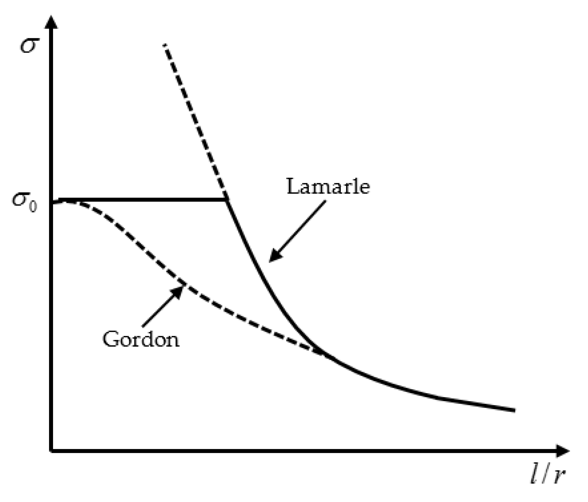
Euler’s analytical conclusion supported the experimental results obtained by Musschenbroek [13] for slender wooden columns. However, Coulomb discarded the result of Musschenbroek and concluded that the breaking strength was independent of length, based on experiments on masonry columns [9]. Duleau, Hodgkinson, Considère, and Engesser discussed Euler’s formulation and its exclusive validity for “slender” columns [13,14,15,16,17]. Moreover, Hodgkinson proposed an empirical formula for the design of short columns based on the experimental investigations on cast-iron columns. In the year 1845, Lamarle proposed a critical load expression in terms of the critical stress and stated that Euler formulation is applicable when the critical stress (σcr) is less than the elastic limit (σ0) for the constructional material in use. In other words, it is applicable for the struts whose slenderness ratio (l/h) is greater than the limit value given as follows i.e., Equation (3) [18]:
where r is the radius of gyration about the weaker axis of the column. Although there is no record of whether Lamarle’s suggestion was used anywhere practically, the formula suggested by Gordon provides the same result as Lamarle’s model, and this is verified both for large and small slenderness ratios [19]. Figure 2 shows some typical design curves, as conventionally obtained in terms of stress and slenderness ratio, based on Lamarle and Gordon models.
The proportionality between the stress and the strain was proposed by Young [20]. Johnson et al. [21] suggested using Euler’s formula by incorporating modifying constant, which is similar to the use of equivalent length coefficient, k.
It is to be noted that, despite considering all the assumptions to transform a real column into an ideal column, the existence of perfectly clamped or pinned boundary conditions at either end and no demand of flexural strength from compression members are hard to achieve. In real problems, these assumptions rarely meet since columns in framed structures are supposed to have sufficient flexural rigidity and restrain. Due to this gap, the use of interaction equations is favoured which is based on Ayrton-Perry’s approach [22]. They first related the concept of the elastic critical stress to the failure stress, which was later simplified further in [23]. Herein, the average compressive stress (fc), the allowable compressive stress in an axially loaded strut , the resultant compressive stress due to bending about the rectangular axis , and the allowable compressive stress for a member subjected to bending are related as per Equation (4) using the well-known beam-column interaction:
3. Buckling Failures
3.1. Self-Buckling
Self-buckling is a phenomenon wherein a column buckles under its own weight; these columns are commonly known as heavy columns. Generally, self-buckling is not considered since it is assumed that the weight of the column is small, compared to the applied axial loads. However, there may be cases in which self-buckling may govern and hence need attention. Self-buckling was first investigated in 1881 by Greenhill [24], and based on his analysis, he proposed that a vertical column may buckle under its own weight if its length exceeds, as given in the following (Equation (5)):
where ρ is the density of column material, E is Young’s modulus, I is the moment of inertia of column, g is gravitational constant, and A is the cross-sectional area of the column.
Duan and Wang [25] considered buckling of heavy columns and presented an analytical solution in terms of hypergeometric function. They highlighted the fact that buckling capacities were not only dependent on end support condition, shape, size, material but also on the weight. They suggested using a fourth-order differential equation instead of second order. Later on, Darbandi et al. [26] presented closed-form solutions for variable section columns subjected to distributed axial force. Herein, the column was modelled using the Euler’s-Bernoulli theory, and solutions were presented using the singular perturbation method of Wentzel-Kramers-Berilloui (WKB), see [26].
In the year 2010, Wei et al. [27] outlined a procedure to compute the buckling load of prismatic and nonprismatic columns under self-weight and tip force. This method did not use Bessel’s function as others [25], which strongly depends on the form of an ordinary differential equation with a variable coefficient [27]. Huang and Li [28] studied the column with a nonuniform section using Fredholm’s integral equation and presented closed-form solutions. Fredholm’s equation transformed the exercise of finding solutions of differential equations to simple algebraic expressions [28]. Later on, Riahi et al. computed the buckling capacity of columns with variable moment of inertia through the slope-deflection method, and dimensionless charts were proposed [29]. On the same line of study, columns with variable inertia (trigonometric-varied inertia column) iteration-perturbation method was applied and obtained results were compared with the result obtained by modelling the same column in ANSYS by Afsharfard and Farshidianfar [30]. Later on, detailed work was reported by Nikolić and Šalinić [31], wherein they assumed that the column is doubly symmetric to apply the method of rigid elements in order to perform buckling analysis of columns with continuously varying cross section and multistepped columns under different boundary conditions.
The described method removes the limitation of the existing rigid body element approach. This method also serves an additional advantage that the boundary condition can be introduced without any extra calculation. However, the limitation of this method lies in the discretisation of elastic segments with rigid segments [31].
3.2. Failure of Inelastic or Short Columns
Duleau, Hodgkinson, Considère, and Engesser, while working independently, suggested that Euler’s formula is valid only for slender columns. It is to be noted here that Hodgkinson had already suggested an empirical formula which was used for the design of short columns. However, there was a need to develop a theory which can govern the failure of short columns or columns with a smaller slenderness ratio [14,15,16,17]. Considering this, Engesser suggested tangent modulus theory, wherein he assumed that axial load was increasing during the transition from straight to the bent position and presented the value of critical stress in terms of tangent modulus (Et) as follows as given by Equation (6):
In the same year, Considère suggested that, if an ideal column is subjected to load greater than the proportional load, the column begins to bend, and stresses on the concave side increase according to tangent modulus theory, whereas, on the convex side, stress peaks decrease according to Hooke’s law. He defined critical load by employing , which is a function of average stress in the column. He also suggested that the value should lie in between the modulus of elasticity and the tangent modulus. Later on, in 1995, the error in tangent modulus theory was put forward by Jasinski, and he pointed out that determination of function which describe was impossible to find theoretically [32]. After this, a double modulus theory was developed by Karman and proposed the actual evaluation of for rectangular cross section and idealised H-section consisting of infinitely thin flange and negligible web. The general expression for the critical stress σcr was thus defined in terms of reduced modulus, [33] by Equations (7) and (8), respectively as:
where and are the moment of inertia of either side of the section about the neutral axis. Since then, the value of has been evaluated by several authors.
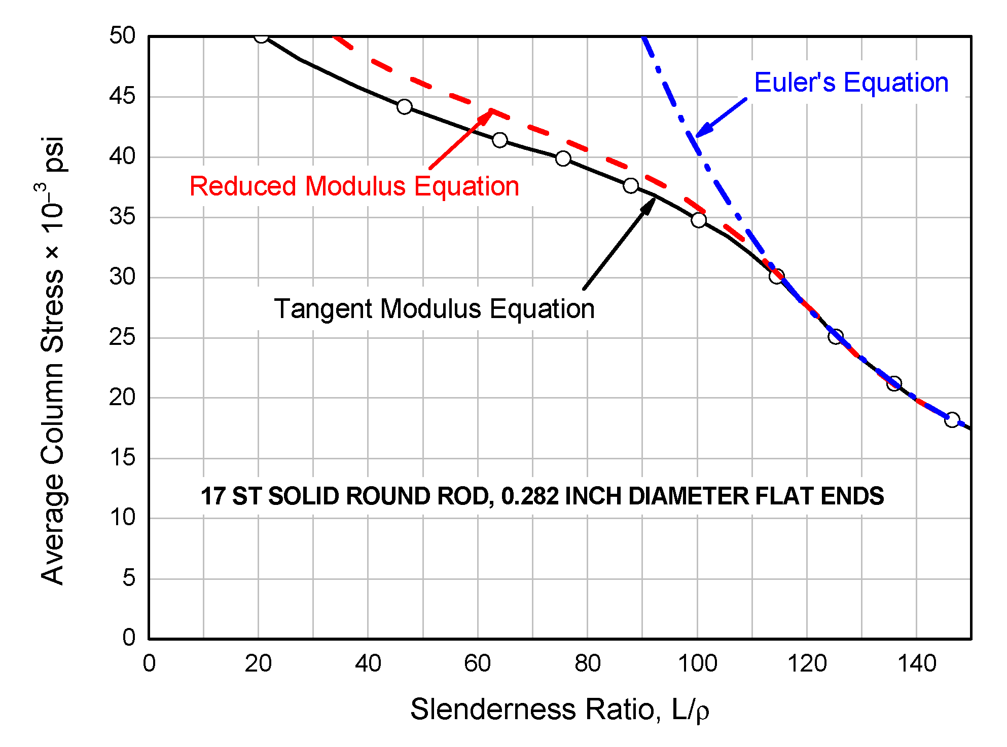
In 1947, using an imaginary column, Shanley concluded that there will be bending once the tangent modulus load is exceeded following which axial load increases and reaches a maximum value which lies in between the tangent modulus load and reduced modulus load, and there will be stress reversal once the bending deformation becomes finite. In other words, Shanley’s analysis clearly described that the first bifurcation will occur at tangent load and a sequence of equilibrium can be constructed in between two limiting loads, i.e., tangent load and double modulus load. Shanley thus proposed an interaction curve to link eccentricities to the tangent modulus theory in order to apply his theory for practical problem and design calculations [34,35]. In this regard, Figure 3 compares the average stress for different slenderness ratios, as collected from the experimental investigation of a specimen (aluminium solid round rod with 0.72 cm diameter having flat ends) discussed in [36].
Later on, a model similar to Shanley was analysed by Johnston by replacing the two-area element with a solid rectangular segment and determined the magnitude of stress distribution for various loads above the tangent modulus load across the section [37]. With the advancement in computer technology, computer programs were written by Batterman [38] to find the maximum load for aluminium alloy H-section with finite web areas about weak as well as the strong axis of bending, in both initially straight position and with initial curvature [38]. In 1987, Groper and Kenig proposed the inelastic stability of stepped columns with the help of Newton’s method or bisection method [39]. In general, the Engesser-Shanley definition for the critical load of a column in an inelastic range is widely acceptable. The same concept is extended for structural steel columns having initial stress due to differential cooling, although the material is in an elastic range.
3.3. Failure of Imperfect Long Columns
Long columns, more than short ones, are notoriously sensitive to initial imperfections, defects, etc. Hence, they necessitate careful investigations since a minor change in the loading and geometrical parameters may lead to their sudden failure. It is well accepted that perfect columns are theoretical identities, and in practice, their behaviour is altogether different. One of the important examples of such columns is a walking stick which is subjected to a large amount of eccentricity.
There exists a wide scatter of results for long columns, due to many reasons, and some of the motivations include nonideal supports, plastic behaviour, the interaction of buckling modes (wherein local buckling of columns is more important), along with possible residual stresses. Due to these imperfections, column behaviour is altogether different practically, in comparison with its theoretical treatment, and the reason for this may be attributed to the treatment of these imperfections. Thus, these columns primarily fail due to elastic instability. Section 4 reports further details about the failure of imperfect long columns.
4. Imperfections in Long Columns
4.1. Imperfections Due to Large Deformations
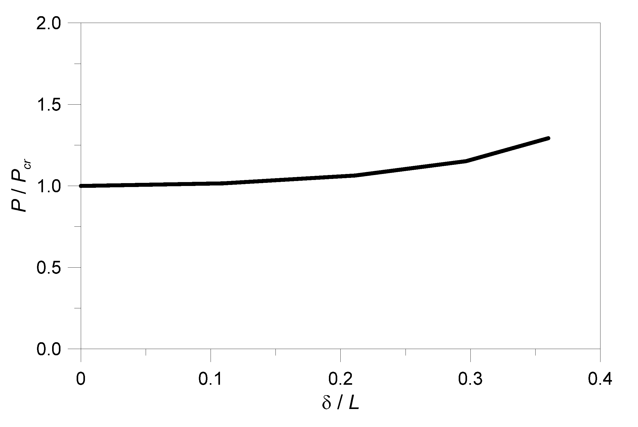
It is well understood that Euler’s original formulation was based on some defined assumptions, and hence, he modelled the behaviour of ideal columns which hardly exist in the reality of the structures. In order to apply his theories to practical problems of engineering, it becomes important to understand the difference in the behaviour of a real and an ideal column. This result can be achieved by removing the various assumptions, one by one, and then analysing the column response. One of the prominent assumptions in Euler’s theory, for example, is that all deformations are considered as “small”. This results in curvature (1/R) of deflected shape of a column of length (L) with flexural rigidity (EI), subjected to axial load (P), with pinned boundary condition on either edge becomes equal to double differentiation of deflection (), thus neglecting (), as in the following [40] given by Equations (9) and (10) as:
where is the slope of deflected shape at support, and Equation (9) represents the solution in terms of mid-height deflection, , applied load, P, and Euler load,.
According to [40], Figure 4 shows the variation of P/Pcr with δ/L and highlights that the estimation of the expected critical load by linear theory is valid for a considerable range of deformations. The reason for such a behaviour is attributed to the fact that for most of the columns, a combination of bending and axial stresses reaches the proportionality limit long before the difference between linear and nonlinear theory becomes notable.
4.2. Imperfections Due to Initial Curvature and Eccentric Loading
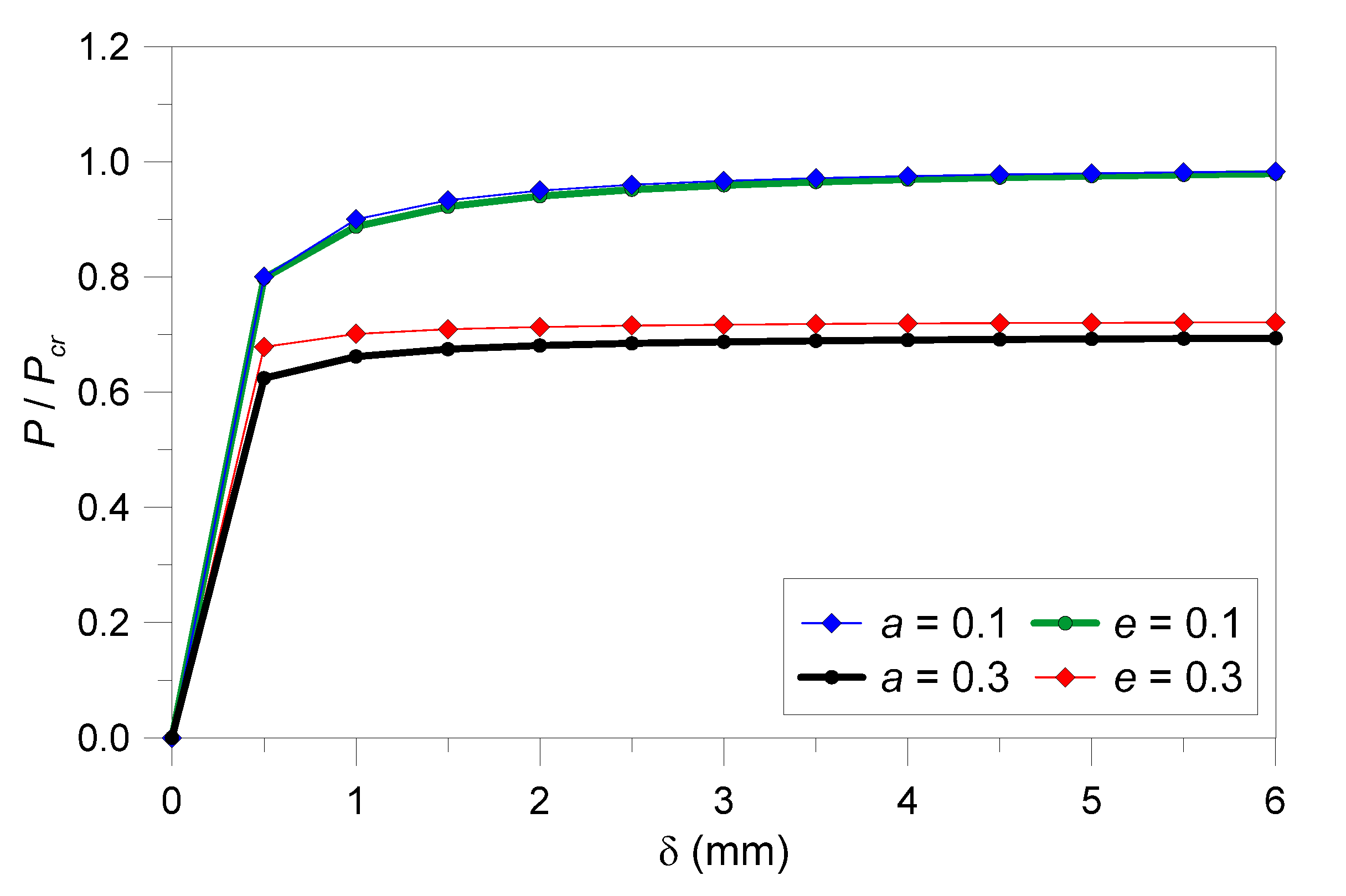
It was Young who, in 1807, tried to find out the effect of eccentricity (e) and initial curvature on the load-carrying capacity of a given column [41]. However, his original research results were not presented in usable form. Later on, during the year 1858, Scheffler [42] presented the complete solution for eccentrically loaded columns, by taking into account the effect of direct stress and bending stress. This solution is now commonly known as the “Secant Formula” (SF).
It is important to highlight, in this context, that the SF is accurate until the predicted stresses are within the elastic limit of the constructional material in use. The behaviour of a column with a given initial curvature or a column subjected to eccentric load is more or less the same, considering the fact that, in either case, the behaviour of the column is the same. Further, if the initial imperfections are small, the original Euler’s formula results in a fairly accurate estimation of the total compressive load which a straight slender member can support.
Equations (11) and (12), in this regard, describe the correlation between the Euler’s load for an ideal column (Pcr) and the critical load (P) for a column either having a certain initial curvature (a) or subjected to eccentric loading (e). Figure 5 shows the graphical interpretation of Equations (11) and (12) for different values of eccentricity and initial curvature. The example calculations are carried out by taking into account Equations (11) and (12) by assuming the different values of δ, along with a and e to consider the initial curvature or eccentricity, respectively.
Along with that, the graph also shows that it does not matter how the initial imperfection is introduced in a perfect column, given that the critical load for an imperfect column will always be smaller than the critical load of the perfect one.
4.3. Imperfections Due to Variable Stiffness
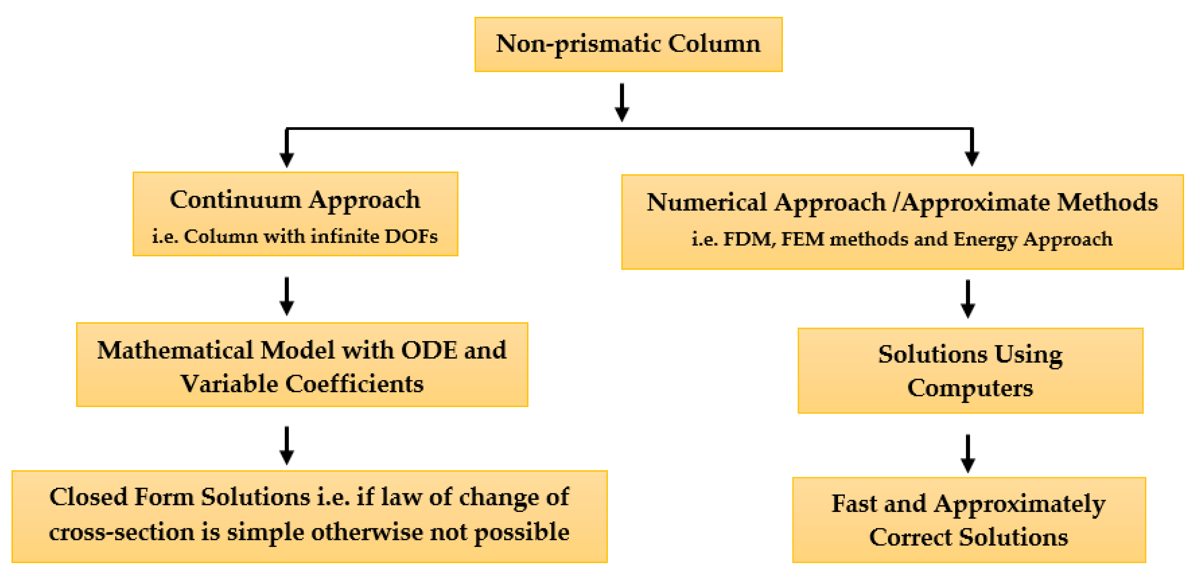
Euler formula is derived for prismatic sections and in an attempt to increase the buckling capacity of columns, the researcher focused on the use of nonprismatic sections. This results in a variable moment of inertia (I) along the longitudinal axis. It is to be noted that columns with nonprismatic sections can be studied in two ways, as shown in Figure 6. Among these two major approaches, it can be noticed that several researchers employed a continuum approach using different functions and variables to report closed-form solutions. At the same time, other researchers employed numerical approaches/approximate methods to arrive at acceptable solutions.
Finally, it is also well accepted that a given uniform section column is overdesigned everywhere, except the point at which the maximum bending moment occurs, and in need to optimise the buckling capacity of the column, some material can be taken out from the overdesigned section and placed at the point at which the maximum moment is occurring. A number of scientists developed this idea as reported in Table 1. The overall research efforts conducted by several researchers in understanding the behaviour of nonprismatic columns using the two major approaches from Figure 6 are summarised in Table 1, with evidence of methods and outcomes.
4.4. Imperfections Due to Functionally Graded Material
From the basic equation of Euler’s [5] one can directly infer that the buckling capacity of columns can also be varied by varying the modulus of elasticity. This method was not preferred until the technology advances to a level that variation of modulus of elasticity either in the axial or longitudinal direction was feasible. Based on the literature, it is observed that it is still a relatively unexplored area. In order to increase the buckling capacity of the column, it was suggested to vary the modulus of elasticity, but the solution of instability becomes difficult to compute. Signer [74] investigated the buckling solution for columns with continuous monotonic variations of flexural rigidity along the column. Fixing the origin at one end and x coordinate running along the centre line, variation of modulus of elasticity (E) and moment of inertia (I) were assumed as follows by Equation (13):
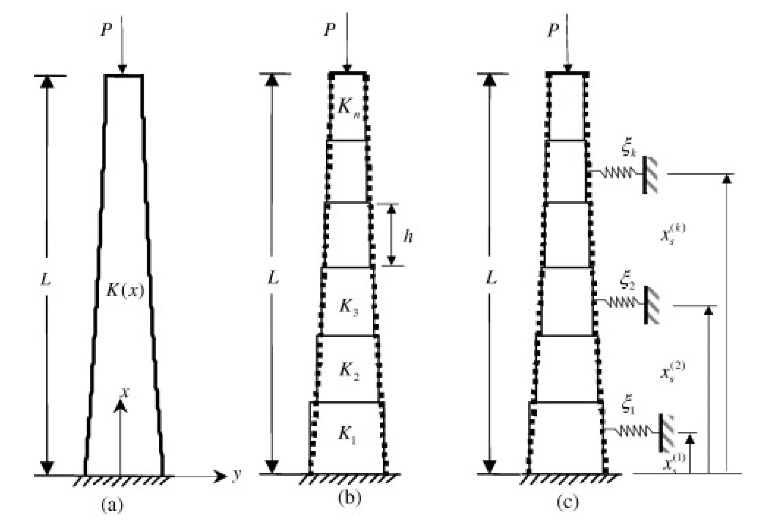
It is to be noted that compressed members used in the civil structure are supported at the intermediate point (bracing). Considering the importance of the intermediate restraints, the study in [75] approximated a column with spatial variation of flexural stiffness due to material gradation or nonisoperimetric shape by an equivalent column with piecewise constant geometrical and material properties (Figure 7). This method uses a transcendental function that results in a closed-form solution of uniform columns. The suggested method was unique because the mathematical model preserves the properties of a continuous system by containing the infinite eigenvalues corresponding to all higher buckling modes [75]. The buckling analysis of axially graded columns was conducted by Huang and Li [28]. They transformed the governing differential equation with variable coefficients to Fredholm’s integral equation which were further reduced to a system of algebraic equations. The accuracy of the suggested procedure was confirmed by comparing the obtained result with the available closed-form and numerical solutions. The significant role of their work was that, unlike other research, it was not restricted only to suitable buckling mode. Through this method, one can successfully solve the problem of buckling, if the variation of flexural rigidity was polynomial, trigonometric, or exponential function.
Recently, Elishakoff [76] studied the buckling of columns made from functionally graded material in an axial direction. The study was limited to find the polynomial variation of modulus of elasticity, E such that the buckling value exceeds in case of cantilever column whose cross-sectional area was kept constant. In another recent investigation, Rychlewska [77] presented buckling solutions for a beam with clamped-clamped, hinged-hinged, and hinged-clamped boundary conditions with an exponential variation of material properties in the axial direction and subjected to distributed load in exponential form.
4.5. Imperfections Due to Elevated Temperature or Fire Exposure
Specific attention can be paid to the buckling analysis of columns with variable stiffness, as in Section 4.3, but with a focus on stiffness variations due to the use of materials that are remarkably sensitive to temperature variations, as well as for resisting cross section that may suffer for long-term temperature exposure. This is the case of load-bearing members that are susceptible to elevated temperature exposure, and even fire, or any kind of phenomena that can be represented by a “thermal gradient” for the resisting cross section to analyse.
Most of the research studies, in this regard, are relatively recent and specifically focused on columns composed of steel [78,79,80], reinforced concrete [81,82,83,84], timber [85,86,87].
Developments in building technology and design strategies are even more frequently focused on innovative laminated glass solutions that are bonded by thermoplastic layers [88,89,90,91] or even composite-laminated insulated panels in which both mechanical and climatic loads can severely affect the overall column buckling performance. In this last case, thermal exposure effects do necessarily coincide with extreme accidents since fire loading can have marked effects on the overall mechanical performance, given the typically small thickness that is of common use in structural glass applications. Besides different materials and characteristics that are used for these members, the common aspect of the above documents is represented by the progressive bending weakness deriving from the degradation of the constituent materials. Therefore, the total compressive load acts on a resisting section and member that prematurely collapses due to its lack of load-bearing capacity. From a practical point of view, the shared feature for the cited literature studies is the basic trend to define standardised design buckling curves for columns made of mostly different constructional materials and thus to collect, in a simplified and univocal formulation, all the possible uncertainties and effects due to material behaviours, eccentricities, imperfections [92].
Even more attention is indeed required for load-bearing members in general that can be subjected to scattered thermal patterns and are thus potentially characterised by a number of critical cross sections.
Additionally, in this latter case, the first efforts are certainly related to the classical material for buildings, thus steel members. Alpsten [93] showed, for example, that residual nonuniform thermal stresses can severely affect the column buckling performance of a given member and result in even more pronounced degradation than geometrical initial imperfections. Culver [94] also focused on the analysis of pinned columns with thermal exposure. The study proved that severe thermal gradients in the mid-span region of columns are typically associated with a remarkable loss of global buckling capacity. While such a concept can be intuitive—due to stiffness reduction—this is in contrast with the discussion by Hoffend [95]. The reason is in the idealisation of the thermal gradient profile. The generally recognised idea, finally, is that thermal gradient effects can be generally schematised in the form of an equivalent initial imperfection. Therefore, the overall buckling performance of an axially loaded member in compression can be severely compromised. On the other hand, this issue can be efficiently addressed for safe design by means of conventional calculation methods that include a given initial geometrical imperfection.
5. Conclusions
The problem investigated by Euler was much simpler since it did not involve finding the solution of differential equation with varying coefficient because neither the material properties nor the cross-sectional dimensions were changing. However, in an attempt to maximise the buckling capacity of the column, modifications were performed in the column due to which the differential equation governing the mathematical model is left with varying coefficients. This review paper provides a complete synopsis of the development of various theories related to column buckling. A significant number of methods were recalled to obtain close-form solutions, but providing evidence for each one of them had certain intrinsic restrictions—either the buckling shape was assumed to be governed by a specific function or the distribution of flexural stiffness was not random. Moreover, all the discussed methods in the literature showed rather good agreement with some experimental results available in the literature. However, which one of them is more suitable to find the solution for a given arbitrary variation of coefficients still remains an unanswered question. In the self-buckling of columns, more research emphasis is required for the proper discretisation of elastic segments with rigid segments. For short column analysis, detailed experiments with various materials are one of the areas wherein research still needs to be carried out. In long columns analysis, more emphasis shall be put on the development of closed-form solution with variable moment of inertia with emphasis on varying material properties along the length of the column. Further, different functions can be developed to investigate the variation of modulus of elasticity and its effect on the buckling strength of columns. Furthermore, attention is indeed required for load-bearing members in general that can be subjected to scattered thermal patterns and are thus potentially characterised by a number of critical cross sections. This can be achieved by incorporating the effect of thermal gradient in terms of initial imperfections.
Author Contributions
The reported work is carried out authors as a team wherein Conceptualization, M.D.G.; methodology, M.D.G. and C.B.; software, A.S.; validation, A.S., A.P.K. and L.M.G.; formal analysis, M.D.G., C.B. and A.S..; investigation, M.D.G., C.B., A.S., A.P.K. and L.M.G.; resources, A.S. and M.D.G.; data curation, M.D.G., C.B. and A.S.; writing—original draft preparation, M.D.G., C.B. and A.S.; writing—review and editing, M.D.G., C.B., A.P.K. and L.M.G.; visualization, M.D.G. and C.B.; supervision, M.D.G.; project administration, L.M.G.; funding acquisition. All authors have read and agreed to the published version of the manuscript.
Funding
This research received no external funding.
Institutional Review Board Statement
Not applicable.
Informed Consent Statement
Not applicable.
Data Availability Statement
Data will be available upon request.
Acknowledgments
Authors acknowledge the support and encouragement provided by Director, VNIT Nagpur, India. MDPI is also acknowledged for the invited free-of-charge submission of this manuscript in the special issue “Innovation in Structural Analysis and Dynamics for Constructions” (C.B. Guest Editor vouchers).
Conflicts of Interest
The authors declare no conflict of interest.
References
- Hooke, R. Lectures de Potentia Restitutiva, or of Spring Explaining the Power of Springing Bodies; John Martyn: London, UK, 1678; pp. 331–388, reprinted, of R. T.Günther, Early Sciences in Oxford 8, Oxford, 1931. [Google Scholar]
- Hales, T.A.; Pantelides, C.P.; Reavele, L.D. Analytical buckling model for slender FRP-reinforced concrete columns. Compos. Struct. 2017, 176, 33–42. [Google Scholar] [CrossRef]
- Cheng, W.-S. Repair and reinforcement of timber columns and shear walls–A review. Constr. Build. Mater. 2015, 97, 14–24. [Google Scholar] [CrossRef] [Green Version]
- Bedon, C.; Kalamar, R.; Eliasova, M. Low velocity impact performance investigation on square hollow glass columns via full-scale experiments and Finite Element analyses. Compos. Struct. 2017, 182, 311–325. [Google Scholar] [CrossRef]
- Euler, L. Euler’s calculation of buckling loads for columns of non uniform section. In The Rational Mechanics of Flexible or Elastic Bodies 1638–1788; Orell FüssliTurici, Societatis Scientiarum Naturalium Helveticae: Zurich, Switzerland, 1960; pp. 345–347, Originally published in 1757. [Google Scholar]
- Euler, L. De altitudinecolumnarum sub proprioponderecorruentium. Acta Acad. Sci. Petropolitanae 1780, 1, 163–193. (In Latin) [Google Scholar]
- Euler, L. Determinatioonerum, quaecolumnaegestarevalent. Acta Acad. Sci. Petropolitanae 1947, 1, 121–145. (In Latin) [Google Scholar]
- Euler, L. Exameninsignispuradoxi in theoria column arumoccurentis. Acta Acad. Sci. Petropolitanae 1780, 1, 146–162. (In Latin) [Google Scholar]
- Coulomb, C.A. Essai sur une Application des Regles de Maximis et Minimis a Quelques Problemes de Statiquerelatifs a L’architecture; Academie Royale Des Sciences: Paris, France, 1773; Volume 7, pp. 343–382. [Google Scholar]
- Dinnik, A.N. Buckling under own weight. Proceeding Don Polytech. 1912, 1, 19. (In Russian) [Google Scholar]
- Dinnik, A.N. Design of column of varying cross section” Transactions of American Society of Mechanical Engineering. Appl. Mech. 1929, 51, 105–114. [Google Scholar]
- Dinnik, A.N. Design of column of varying cross section. Trans. Am. Soc. Mech. Eng. 1932, 54, 105–109. [Google Scholar]
- van Musschenbroek, P. Physicaeexperimentale Set Geometricae de Magnete, Tuborum Capillarium Vitreorum Quespeculorum Attractione, Magnitudine terrae, Cohaerentia Corporum Firmorum Dissertationes: Ut et Ephemerides Meteorologicae Ultrajectinae; Luchtmans, Nova Editio: Viennae, Austria, 1756. [Google Scholar]
- Duleau, A.J.C. Essaitheorique et Experimental sur la Resistance du Fer Forge; Mme.Ve. Courcier, Nabu Press: Paris, France, 1820. [Google Scholar]
- Hodgkinson, E. On the Transverse Strain and Strength of Materials. In Memoirs of the Literary and Philosophical Society of Manchester; 2nd Series; Literary and Philosophical Society of Mancheste: Manchester, UK, 1824; Volume 2–4. [Google Scholar]
- Engesser, F. Ueber die KnickfestigkeitgeraderSUibe. In ZeitschriftfiirArchitektur und Ingenieurwesen; W. Ernst & Sohn: Berlin, Germany, 1889; Volume 35. [Google Scholar]
- Considère, A. Résistance des piècescomprimées. In Congrès International des Procédés de Construction; Libraire Polytechnique: Paris, France, 1891; pp. 3, 371. [Google Scholar]
- Lamarle, E. Memoire sur la flexion du bois. In Annales des Travaux Publics de Belgique; Vandooren, B.J., Ed.; Imprimeur Des Annales Des Travaus Publication: Bruxelles, Belgium, 1845; Volume III, pp. 1–64, Volume IV, pp. 1–36. [Google Scholar]
- Rankine, W.J.M. A Manual of Civil. Engineering; Charles Griffin: London, UK, 1862. [Google Scholar]
- Young, D.H. Rational design of steel columns. Am. Soc. Civ. Eng. Transl. 1936, 101, 442–500. [Google Scholar]
- Johnson, J.B.; Bryan, C.W.; Turneaure, F.E. The Theory and Practice of Modern Framed Structures: Designed for the Use of Schools, and for Engineers in Professional Practice; John Wiley & Sons, Inc.: New York, NY, USA, 1905; p. 561. [Google Scholar]
- Ayrton, W.E.; Perry, J. On struts. Engineer 1886, 62, 464–465. [Google Scholar]
- Robertson, A. The strength of struts. Inst. Civ. Eng. 1925, 1. [Google Scholar] [CrossRef]
- Greenhill, A.G. Determination of the greatest height consistent with stability that a vertical pole or mast can be made, and the greatest height to which a tree of given proportions can grow. Proc. Camb. Philos. Soc. 1881, 4, 65–73. [Google Scholar]
- Duan, W.H.; Wang, C.M. Exact solution for buckling of columns including self-weight. J. Eng. Mech. 2008, 134, 116–119. [Google Scholar] [CrossRef]
- Darbandi, S.M.; Firouz-Abadi, R.D.; Haddadpour, H. Buckling of variable section column under axial loading. J. Eng. Mech. 2010, 136, 472–476. [Google Scholar] [CrossRef]
- Wei, D.J.; Yan, S.X.; Zhang, Z.P.; Li, X.-F. Critical load for buckling of non-prismatic columns under self-weight and tip force. Mech. Res. Commun. 2010, 37, 554–558. [Google Scholar] [CrossRef]
- Huang, Y.; Li, X.F. Buckling analysis of nonuniform and axially graded columns with varying flexural rigidity. J. Eng. Mech. 2010, 137, 73–81. [Google Scholar] [CrossRef]
- Rahai, A.R.; Kazemi, S. Buckling analysis of non-prismatic columns based on modified vibration modes. Commun. Nonlinear Sci. Numer. Simul. 2008, 13, 1721–1735. [Google Scholar] [CrossRef]
- Afsharfard, A.; Farshidianfar, A. Finding the buckling load of non-uniform columns using the iteration perturbation method. Theor. Appl. Mech. Lett. 2014, 4. [Google Scholar] [CrossRef] [Green Version]
- Nikolić, A.; Šalinić, S. Buckling analysis of non-prismatic column: A rigid multibody approach. Eng. Struct. 2017, 143, 511–521. [Google Scholar] [CrossRef]
- Jasinski, F. NocheinWortzu den Knickfragen. Schweiz. Bauztg. 1895, 25, 172. [Google Scholar]
- von Karman, T. Untersuchungen Liber Knickfestigkeit; Mitteilungeniiber Forsclulflgsarbeitenaufdem Gebiete des Ingenieul’lvesens: Berlin, Germany, 1910. [Google Scholar]
- Shanley, F.R. The column paradox. J. Aeronaut. Sci. 1946, 13, 618–679. [Google Scholar] [CrossRef]
- Shanley, F.R. Inelastic column theory. J. Aeronaut. Sci. 1947, 14, 261–268. [Google Scholar] [CrossRef]
- Templin, R.L.; Strum, R.G.; Hartmann, E.C.; Holt, M. Column strength of various aluminium alloys. In Aluminium Research Laboratories Technical Paper 1; Aluminium Company of America: Pittsburgh, PA, USA, 1938. [Google Scholar]
- Johnston, B.G. Buckling behavior above the tangent modulus load. J. Eng. Mech. Div. ASCE 1961, 87, 79–100. [Google Scholar] [CrossRef]
- Batterman, R.H.; Johnston, B.G. Behavior and maximum strength of metal columns. J. Struct. Div. ASCE 1967, 93, 205–230. [Google Scholar] [CrossRef]
- Groper, M.; Kenig, M.J. Inelastic buckling of nonprismatic column. J. Eng. Mech. 1987, 113, 1233–1239. [Google Scholar] [CrossRef]
- Chajes, A. Principles of Structural Stability; Prentice Hall: Hoboken, NJ, USA, 1974. [Google Scholar]
- Young, T. A Course of Lectures on Natural Philosophy and the Mechanical Arts; Royal Society: London, UK, 1807; Volume 1, 2, pp. 135–156. [Google Scholar]
- Salmon, E.H. Columns by, Frowde; Hodder & Stoughton: London, UK, 1920. [Google Scholar]
- Murphy, G.M. Ordinary Differential Equations and Their Solutions; D. Van Nostrand: New York, NY, USA, 1960. [Google Scholar]
- Gere, J.M.; Carter, W.O. Critical buckling loads for tapered columns. J. Struct. Div. Proc. 1962, 1, 1–12. [Google Scholar]
- Lagrange, J.-L. Sur la figure des colonnes. In Oeuvres de Lagrange (Publ. de M.J.-A. Serret); Gauthier-Villars: Paris, France, 1868; Volume 2, pp. 125–170. [Google Scholar]
- Clausen, T. Űber die Form architektonischerSäulen. Bull. Phys. Math. De L’academie St. Petersburg 1851, 9, 368–379. [Google Scholar]
- Keller, J.B. The shape of the strongest column. Arch. Ration. Mech. Anal. 1960, 5, 275–285. [Google Scholar] [CrossRef]
- Tadjbakhsh, I.; Keller, J.B. Strongest columns and isoperimetric inequalities for eigenvalues. J. Appl. Mech. 1962, 29, 159–164. [Google Scholar] [CrossRef]
- Taylor, J.E. The strongest column: An energy approach. J. Appl. Mech. 1967, 34, 486–487. [Google Scholar] [CrossRef]
- Martin, G.H. A procedure for determining the critical load for a column of varying section. J. Aeronaut. Sci. 1946, 13, 135–140. [Google Scholar] [CrossRef]
- Harris, C.O. A suggestion for columns of varying section. J. Aeronaut. Sci. 1942, 9. [Google Scholar] [CrossRef]
- Wilson, J.F.; Holloway, D.M.; Biggers, S.B. Stability experiments on the strongest columns and circular arches. Exp. Mech. 1971, 11, 303–308. [Google Scholar] [CrossRef]
- O’Rourke, M.; Zebrowski, T. Buckling load for nonuniform columns. Comput. Struct. 1977, 7, 717–720. [Google Scholar] [CrossRef]
- Iremonger, M.J. Finite difference buckling analysis of non-uniform columns. Comput. Struct. 1980, 12, 741–748. [Google Scholar] [CrossRef]
- Banerjee, J.R.; Williams, F.W. Exact Bernoulli-Euler static stiffness matrix for a range of tapered beam-columns. Int. J. Numer. Methods Eng. 1985, 21, 2289–2302. [Google Scholar] [CrossRef]
- Smith, W.G. Analytic solutions for tapered column buckling. Comput. Struct. 1988, 28, 677–681. [Google Scholar] [CrossRef]
- Chen, Y.Z.; Cheung, Y.K.; Xie, J.R. Buckling loads of columns with varying cross-section. J. Eng. Mech. 1989, 115, 662–667. [Google Scholar] [CrossRef]
- Eisenberger, M. Buckling loads for variable cross-section members with variable axial forces. Int. J. Solids Struct. 1991, 27, 135–143. [Google Scholar] [CrossRef]
- Lee, S.Y.; Kuo, Y.H. Elastic stability of non-uniform column. J. Sound Vib. 1991, 148, 11–24. [Google Scholar] [CrossRef]
- Vaziri, H.H.; Xie, J. Buckling of columns under variably distributed axial loads. Comput. Struct. 1992, 45, 505–509. [Google Scholar] [CrossRef]
- Arbabi, F.; Li, F. Buckling of variable cross-section columns: Integral-equation approach. J. Struct. Eng. 1991, 117, 2426–2441. [Google Scholar] [CrossRef]
- Qiusheng, L.; Hong, C.; Guiqing, L. Stability analysis of bars with varying cross-section. Int. J. Solids Struct. 1995, 32, 3217–3228. [Google Scholar] [CrossRef]
- Timoshenko, S.P.; Gere, J.M. Theory of Elastic Stability; McGraw Hill: New York, NY, USA, 1961. [Google Scholar]
- Genik, A.N. Scientific Paper of Genik; AN: Moscow, Russia, 1950. [Google Scholar]
- von Kármán, T.; Biot, M. Mathematical Methods in Engineering; McGraw-Hill: New York, NY, USA, 1940. [Google Scholar]
- Duncan, W.J. Galerkin’s Method in Mechanics and Differential Equations; Aeronautical Research Committee Reports and Memoranda; H.M.S.O.: London, UK, 1937; No. 1798. [Google Scholar]
- Elishakoff, I.; Rollot, O. New closed-form solutions for buckling of a variable stiffness column by mathematica. J. Sound Vib. 1999, 224, 172–182. [Google Scholar] [CrossRef]
- Elishakoff, I. A closed form solution for the generalized Euler problem. Proc. R. Soc. Lond. A Math. Phys. Eng. Sci. 2000, 456. [Google Scholar] [CrossRef] [Green Version]
- Li, Q.S. Buckling analysis of multi-step non-uniform columns. Adv. Struct. Eng. 2000, 3, 139–144. [Google Scholar] [CrossRef]
- Li, Q.S. Exact solutions for buckling of non-uniform column under axial concentrated and distributed loading. Eur. J. Mech.-A/Solids 2001, 20, 485–500. [Google Scholar] [CrossRef]
- Wang, C.M.; Wang, C.Y.; Reddy, J.N. Exact Solutions for Buckling of Structural Members; CRC: Boca Raton, FL, USA, 2005. [Google Scholar]
- Lee, B.K.; Carr, A.J.; Lee, T.E.; Kim, J. Buckling loads of columns with constant volume. J. Sound Vib. 2006, 294, 381–387. [Google Scholar] [CrossRef]
- Totry, E.M.; Altus, E.; Proskura, A. Buckling of non-uniform beams by a direct functional perturbation method. Probabilistic Eng. Mech. 2007, 22, 88–89. [Google Scholar] [CrossRef]
- Siginer, A. Buckling of columns of variable flexural rigidity. J. Eng. Mech. 1992, 118, 640–643. [Google Scholar] [CrossRef]
- Singh, K.V.; Li, G. Buckling of functionally graded and elastically restrained non-uniform columns. Compos. Part B Eng. 2009, 40, 393–403. [Google Scholar] [CrossRef]
- Elishakoff, I. Buckling of a column made of functionally graded material. Arch. Appl. Mech. 2012, 82, 1355–1360. [Google Scholar] [CrossRef]
- Rychlewska, J. Buckling analysis of axially functionally graded beams. J. Appl. Math. Comput. Mech. 2014, 13, 103–108. [Google Scholar] [CrossRef] [Green Version]
- Janss, J.; Minne, R. Buckling of steel columns in fire conditions. Fire Saf. J. 1981, 4, 227–235. [Google Scholar] [CrossRef]
- Ng, K.T.; Gardner, L. Buckling of stainless steel columns and beams in fire. Eng. Struct. 2007, 29, 717–730. [Google Scholar] [CrossRef]
- Gomes, F.C.T.; Providencia e Costa, P.M.; Rodrigues, J.P.C.; Neves, I.C. Buckling length of a steel column for fire design. Eng. Struct. 2007, 29, 2497–2502. [Google Scholar] [CrossRef] [Green Version]
- Tie, L.L. Fire Resistance of Reinforced Concrete Columns: A Parametric Study. J. Fire Prot. Eng. 1989, 1, 121–129. [Google Scholar]
- Rodrigues, J.P.C.; Laím, L.; Correia, A.M. Behaviour of fiber reinforced concrete columns in fire. Compos. Struct. 2010, 92, 1263–1268. [Google Scholar] [CrossRef]
- Han, L.H.; Tan, Q.-H.; Song, T.-Y. Fire Performance of Steel Reinforced Concrete Columns. J. Struct. Eng. 2015, 141. [Google Scholar] [CrossRef]
- Gernay, T. Fire resistance and burnout resistance of reinforced concrete columns. Fire Saf. J. 2019, 104, 67–78. [Google Scholar] [CrossRef]
- Malhotra, H.L.; Rogowski, B.F. Fire resistance of laminated timber columns. Fire Res. Notes 1967, 671, 1–60. [Google Scholar]
- Schnabl, S.; Turk, G.; Planinc, I. Buckling of timber columns exposed to fire. Fire Saf. J. 2011, 46, 431–439. [Google Scholar] [CrossRef] [Green Version]
- Wiesner, F.; Bisby, L. The structural capacity of laminated timber compression elements in fire: A meta-analysis. Fire Saf. J. 2019, 107, 114–125. [Google Scholar] [CrossRef]
- Amadio, C.; Bedon, C. Buckling of Laminated Glass Elements in Compression. J. Struct. Eng. 2011, 137. [Google Scholar] [CrossRef]
- Oikonomopoulou, F.; van den Broek, E.A.M.; Bristogianni, T.; Veer, F.A.; Nijsse, R. Design and experimental testing of the bundled glass column. Glass Struct. Eng. 2017, 2, 183–200. [Google Scholar] [CrossRef] [Green Version]
- Aiello, S.; Campione, G.; Minafo, G.; Scibilia, N. Compressive behaviour of laminated structural glass members. Eng. Struct. 2011, 33, 3402–3408. [Google Scholar] [CrossRef]
- Bedon, C.; Amadio, C. Buckling analysis and design proposal for 2-side supported double Insulated Glass Units (IGUs) in compression. Eng. Struct. 2018, 168, 23–34. [Google Scholar] [CrossRef] [Green Version]
- Bedon, C.; Amadio, C. Design buckling curves forglass columns and beams. Struct. Build. 2015, 168, 514–526. [Google Scholar] [CrossRef]
- Alpsten, G.A. On numerisk simulering av barformagan hos isolerade stalpelareutsatta for brandpaverkan. In Nordiskafroskningsdagar for Stalbygguad; ETH, Zurich: Stockholm, Sweden, 1970. (In German) [Google Scholar]
- Culver, C.G. Steel column buckling under thermal gradient. ASCE J. Struct. Div. 1972, 92, 1853–1865. [Google Scholar] [CrossRef]
- Hoffend, F. Brandverhalten von Stahlstutzenbeiausmittiger Lasteintung. In Dehnbehindeung ode teilweiser Beckleidun; Sonderforschungsbereich 148, Brandverhalten von Bauteilen, Arbeitsbericht, Teil; VS Verlag für Sozialwissenschaften, Wiesbaden Technical University: Wiesbaden, Germany, 1978–1980. (In German)
Figure 1.
Examples of column buckling for constructional members: (a) FRP-reinforced concrete columns (reproduced from [2] with permission from Elsevier®, license n. 5026030791841); (b) repaired timber columns (reproduced from [3] with permission from Elsevier®, license n. 5026030922470); and (c) hollow square glass columns (reproduced from [4] with permission from Elsevier®, license n. 5026031011542).

Figure 2.
Comparison of design curves for compression members.

Figure 3.
Comparison of experimental data and column theories.

Figure 4.
Normalised load-deflection curve.

Figure 5.
Normalised load versus deflection curves for a compressed member affected by various amplitudes of initial imperfection.
Figure 5.
Normalised load versus deflection curves for a compressed member affected by various amplitudes of initial imperfection.

Figure 6.
Approaches for the solution of nonprismatic columns.

Figure 7.
Examples of (a) nonuniform and nonhomogeneous axially graded columns, (b) piecewise continuous approximated model (of order n), and (c) axially graded column (order n) with multiple intermediate elastic restraints. Reproduced from [75] with permission from Elsevier®, license n. 5026040108100.


Table 1.
Summary of research on nonprismatic columns using continuum or numerical approaches.
| Ref. | Variable/Method | Column | Remarks/Findings |
|---|---|---|---|
| [12] | Exponential variation of flexural rigidity using power function | Variable stiffness |
|
| [43] | Exponential variation of flexural rigidity using Bessel’s function | Variable stiffness |
|
| [44] | Varying sectional dimension h(x) and second moment of inertia i(x) | Tapered |
|
| [45] | ODE approach | Variable stiffness |
|
| [46] | ODE approach | Variable stiffness |
|
| [47] * | Variational technique | Twisted; arbitrary cross section; pinned ends |
|
| [48] | Continuum approach | Variable stiffness |
|
| [49] | Energy approach | Variable stiffness |
|
| [50] | Approximate method | Uniform or nonuniform shapes |
|
| [52] | Experimental verification | Uniform circular; tapered circular; triangular equilateral |
|
| [53] | Finite-difference approach | Nonuniform |
|
| [54] | Finite-difference method (FDM) through matrix iteration approach | Nonuniform; tapered |
|
| [55] | Bessel’s function | Tapered |
|
| [39] | Continuum approach | Tapered |
|
| [44] | ODE approach | Tapered |
|
| [56] | Energy approach | Fixed-free; square pyramid; truncated cone |
|
| [57] | FEM approach (i.e., power series solution of differential equation with variable coefficients to generate the stiffness matrix) | Variable stiffness |
|
| [58] | Semi-analytical approach | Nonprismatic |
|
| [59] | Four normalised fundamental equations | Constant width and tapered depth; constant depth and tapered width; double tapered |
|
| [60] | New numerical method (i.e., eigenvalue problem transformed into a boundary value problem which can be solved using the numerical integration) | Nonprismatic; self-weight |
|
| [61] | Semi-analytical procedure | Nonprismatic |
|
| [62] | Power function or exponential function and distribution of flexural stiffness along with Bessel’s function | Nonprismatic |
|
| [66] | ODE approach | Variable moment of inertia |
|
| [67] | Fixed polynomial variation of flexural rigidity | Variable moment of inertia | |
| [68] | Transcendental equations, Bessel’s or Lommel’s function | Variable stiffness; self-weight |
|
| [69] | Continuum approach | Variable stiffness |
|
| [70] | Arbitrary distribution of flexural stiffness | Variable stiffness; axially distributed load |
|
| [71] | Eigenvalue approach | Variable stiffness |
|
| [72] | ODE approach | Tapered (parabolic and sinusoidal); polygonal cross section |
|
| [73] | ODE approach with Green’s function |
| |
| [29] | Modified vibrational mode shape (MVM) and energy method | Multistep |
|
* Additionally, Weinberger (unpublished research).
Publisher’s Note: MDPI stays neutral with regard to jurisdictional claims in published maps and institutional affiliations. |
© 2021 by the authors. Licensee MDPI, Basel, Switzerland. This article is an open access article distributed under the terms and conditions of the Creative Commons Attribution (CC BY) license (https://creativecommons.org/licenses/by/4.0/).
Share and Cite
MDPI and ACS Style
Goel, M.D.; Bedon, C.; Singh, A.; Khatri, A.P.; Gupta, L.M. An Abridged Review of Buckling Analysis of Compression Members in Construction. Buildings 2021, 11, 211. https://0-doi-org.brum.beds.ac.uk/10.3390/buildings11050211
AMA Style
Goel MD, Bedon C, Singh A, Khatri AP, Gupta LM. An Abridged Review of Buckling Analysis of Compression Members in Construction. Buildings. 2021; 11(5):211. https://0-doi-org.brum.beds.ac.uk/10.3390/buildings11050211
Chicago/Turabian StyleGoel, Manmohan Dass, Chiara Bedon, Adesh Singh, Ashish Premkishor Khatri, and Laxmikant Madanmanohar Gupta. 2021. "An Abridged Review of Buckling Analysis of Compression Members in Construction" Buildings 11, no. 5: 211. https://0-doi-org.brum.beds.ac.uk/10.3390/buildings11050211
Note that from the first issue of 2016, this journal uses article numbers instead of page numbers. See further details here.