Rehabilitation of Corrosion-Defected RC Beam-Column Members Using Patch Repair Technique

Department of Civil Engineering, Collage of Engineering, University of Babylon, Hillah 51001, Iraq
*
Author to whom correspondence should be addressed.
Buildings 2019, 9(5), 120; https://0-doi-org.brum.beds.ac.uk/10.3390/buildings9050120
Submission received: 18 March 2019
/
Revised: 12 April 2019
/
Accepted: 24 April 2019
/
Published: 10 May 2019
(This article belongs to the Special Issue Reliability Assessment and Sustainable Rehabilitation of Structural Systems)
Abstract
:An experimental study was conducted to evaluate the efficiency of patch repair to rehabilitate corrosion-defected reinforced concrete (RC) beam-column members when exposed to bending moments and axial forces. Ten RC beam-column members were tested under combined constant axial force and four-point transverse load up to failure. Two levels of the constant axial force were applied at either 15 kN or 30 kN (i.e., 25% or 50% of the ultimate design load of the control specimen). The accelerated corrosion process was used to get steel reinforcement corrosion inside the concrete of three levels, 0% and approximately 5% and 20%, according to Faraday’s law. The patch repair technique of cleaning or replacing corroded steel bars and replacing the damaged concrete cover with new mortar was used in this study. The experimental results of the corrosion-defected specimens showed a significant deterioration in the structural performance and the integrity by reducing ultimate capacity, stiffness, serviceability, and ductility. Additionally, the effect of increasing axial force was recorded clearly by reducing the adverse effect of corrosion, especially for defected specimens with high corrosion level. The deterioration of corrosion reinforcement could be overcome when using a patch repair technique, which restored the undamaged state and was shown clearly by using a patch repair technique with replacing corroded steel bars.
1. Introduction
Structural rehabilitation has become an important technique that is necessary for improving and enhancing the efficiency of repairing defected structural members. The deterioration of reinforced concrete (RC) structures along with the contrast and the prices of repairing proceedings have encouraged the introduction of innovative materials and new methods for structure rehabilitation. The most common cause of premature material deterioration is when the structure is exposed to a harsh service environment, and then reinforcement corrosion takes place. Corrosion is similar to cancer for the reinforced concrete structure because it degrades reinforcement, which affects its strength and its life span. Concrete is alkaline in nature with a pore solution that naturally passivizes embedded reinforcing bars, and then protective oxide films of the high alkaline environment are produced. Corrosion can take place when the passive film is removed or is locally damaged. Carbonation-induced and chloride-induced corrosion of the reinforcements are the most common environmental impacts that cause the failure of concrete structures. There are several major defects caused by corrosion, such as early failure of the corroded steel bars due to a reduction in ductility and the area of the cross sectional steel bars, which increases the volume of the bars from corrosion products, and then steel-concrete interface bonding problems can occur [1]. The corrosion of the steel reinforcement affects the mechanical behavior of structures. There are several aspects affected by corrosion, such as, stiffness, serviceability, ductility, and load-carrying capacity. The stiffness of a structure as well as the moment and shear capacities are reduced due to a reduction of the cross section area of bars. Additionally, the ductility, the serviceability and load-carrying capacity are affected by the change in rebar ductility and the cracked concrete surrounding the corroded reinforcements.
There are several techniques for rehabilitation of the corrosion-defected reinforced concrete members. Patch repair is one of the most common rehabilitation methods used to repair structural deterioration. It is the most applicable and skillful technique for rehabilitation of corrosion-defected reinforced concrete areas of existing structures. This rehabilitation technique deals with two levels of corrosion; lower levels up to 15% are rehabilitated by cleaning the corroded steel bars, but the high levels beyond 15% are rehabilitated by replacing corroded bars in respect to the overlap length [2].
With the improvement of modern science and technology, a radical change in structural construction has been observed. The structural constructions of the 1800s are architecturally simple and comprise fewer stories compared to this century’s structures. In the 1900s, slightly more complex architectural parameters were introduced, and the structures became comparatively taller. Now, it has become a challenge for structural and geotechnical engineers to meet the design needs when considering the variation in shapes, vertical irregularities, safety against natural calamities such as wind and earthquakes and economical facts. As the heights of the RC structures increase, they become prone to severe action caused by an earthquake or the wind [3].
For these reasons, many researchers have conveyed great interest in studying high rise RC structures and the effects of wind and earthquakes on its members. Structural elements used in a building with many stories and large structures, such as flexural members, are under combined transverse and axial loading. Reinforced concrete structural members that are subjected to combined axial compression force and transverse flexural load at the same time are called “beam-column” members, and they are mostly used in frame type structures. In this case, these beam-column members are often subjected to lateral forces from wind and earthquake in addition to transverse loads.
Many researchers have shown the effects of corrosion and its degree on the mechanical properties of steel reinforcement in addition to its effect on the behavior and the flexural strength of RC beams. Al-musallam [4] showed the effects of steel reinforcement corrosion on the mechanical properties of steel bars. He found that the ductility of corroded bars was decreased when corrosion levels increased and steel bars with more than a 12.6% corrosion level indicated a brittle behavior. Mangat P.S. and Elgarf M.S. [5] tested 111 RC beams to examine their flexural capacity after being exposed to different levels of reinforcement corrosion by an accelerated corrosion process. They mentioned that the deterioration in the bond strength of the steel-concrete interface was the main cause of decreasing flexural strength. Carlos G. et al. [6] experimentally investigated the influence of fiber reinforcement in the flexural behavior of corrosion-damaged reinforced concrete beams. They conducted that the residual capacity of corroded beams increased for specimens with fiber reinforced concrete compared with plain concrete, and fiber reinforced proved to be the most effective in preventing brittle failure. Ballim Y. and Reid J. C. [7] experimentally studied the influence of corrosion reinforcement on the serviceability state in terms of the deflection of RC beams. They measured the mid-span deflection of specimens subjected to 34% and 23% of the design ultimate load and a period of 30 days of simultaneous accelerated corrosion. Results showed that 6% of the mass of the steel was corroded and beam deflection was increased by 40–70% compared with the control beam. Goitseone M. et al. [8] carried out tests on nine RC beams subjected to four-point loading and corroded using an impressed current to the deformed tensile steel bars and 5% NaCl solution with constant wetting cycles and two different drying cycles. They showed that the ultimate moment capacity of the beams was reduced linearly to the level of corrosion, thus for every 1% of corrosion level, there was a 0.7% reduction in the ultimate capacity. Gu X.L. et al. [9] constructed twelve beams where three beams were corroded by the natural corrosion process and others were corroded by an artificial corrosion process. They noted that the load carrying capacity and the stiffness of the beams decreased with the increase in the corrosion degree. Wenjun Z. et al. [10] experimentally investigated the behavior of corroded RC beams under real chloride environment conditions. The long term corrosion process was used to represent the real structural condition; thus the specimens were stored in a chloride environment for 26 years. The test results showed that less ductility failure of the corroded bars was recorded, and the ultimate elongation reduced more than 50% compared with the non-corroded steel bars. The mode of failure changed for the corroded beams compared to the non-corroded one beams from shear failure to flexural failure due to the large effect of corrosion on the flexural capacity rather than the shear capacity. Torres-Acosta et al. [11] found that structural stiffness was reduced linearly with an increase in the level of corrosion. Yafei M. et al. [12] investigated the effect of corrosion on the steel-concrete interface bond behavior. They found that the corrosive influence on bond strength could be ignored when the corrosion loss was less than 2.4% and that the bond behavior between the smooth bar and the concrete was more sensitive to corrosion than that of the specimen with the deformed bar. Lijum H. et al. [13] experimentally studied the behavior of RC ultra-high toughness cementitious composite beam. They indicated that corrosion clearly affected the load carrying capacity, the deformation, the ductility and the flexural crack patterns of the damaged specimens.
On the other side, there have been several studies on the rehabilitation techniques of RC members with corroded steel reinforcement. Niloufar G. et al. [14] carried out an experimental test on five post-tension corroded, deteriorated, and repaired RC beams. An electrolyte corrosion technique was used to accelerate the reinforcement corrosion inside the concrete. All beams were pre-stressed with two seven 7-wire, low-relaxation strands in addition to ordinary reinforcement with deformed main and secondary bars. The level of corrosion was 15% as weight loss. A patch repair technique of cleaning the corroded steel bars in addition to replacing the damaged concrete cover using new mortar was used in this study. Results showed that using high performance concrete materials as a patch repair without epoxy at the repair substrate interface could significantly restore the structural performance of the deteriorated PT (Post Tension) beams. Garyfalia G. et al. [15] experimentally tested four RC beams under corrosion damage. An acceleration corrosion process with wet/dry cycles was used to get low, medium and high corrosion level. The cement-based repair mortar and two near surface mounted (NSM) fiber reinforced polymer (FRP) laminates were applied to retrofit the deterioration RC beam specimens. The study notes that the patch repair and the NSM strengthening enhanced the load carrying capacity. Al-Saidy et al. [16] study consisted of an experimental program from ten damaged/repaired reinforced concrete beams. Carbon fiber reinforced polymer (CFRP) sheets were used for the external strengthening of the corroded beams. Results showed that the strengthening technique by CFRP sheet for corroded RC beams was capable of maintaining the load carrying capacity, thus the strength of the beams that were damaged due to corrosion was restored to the control state when they were strengthened with CFRP sheets. Almassri et al. [17] investigated the NSM (CFRP) rods as a repair technique for the rehabilitation of defects in the RC beam members of buildings and as a way of restoring the mechanical performance of corrosion-damaged beams. The test results showed that the NSM technique was able to increase the ultimate load capacity of corroded beams and to slightly increase the stiffness. Furthermore, the sufficient ductility could be restored. Rami H. Haddad [18] experimentally investigated the effectiveness of using segmented or continuous U-warp CFRP sheets to retrofit RC beams with corrosion damage. An acceleration corrosion process of dry/wet cycles was used to accelerate corroded main tension bars. The test results showed a significant reduction in the load carrying capacity of about 13% under the corrosion level of 8% (the average weight loss) compared with the control non-corroded beams. Flexural performance of the corroded beams was tested as the load capacity and the stiffness were increased by using the CFRP sheet. Huifeng Z. et al. [19] conducted an experimental program on eight RC beams subjected to an accelerated corrosion process and then rehabilitated with CFRP sheets. These beam specimens were divided into two groups, one that was strengthened with CFRP sheets and one that was un-strengthened. The test results showed that the flexural bearing capacity of the RC beams decreased as the corrosion level of the tensile bars increased. The specimens strengthened with composite materials CFRP sheets gave a positive effect on the load-carrying capacity and the flexural behavior.
Many researchers have studied the effects of corrosion on the behavior and the ultimate strength of RC beams in addition to the studies on the rehabilitation techniques used for this purpose, but no study was found on the experimental study of the structural behavior and ultimate strength of defected/rehabilitated RC beam-column members exposed to bending moments and axial forces. Therefore, the present study concentrated on the experimental investigation of load carrying capacity, serviceability, stiffness, crack patterns, concrete strain, and ductility of RC beam-column members by using a patch repair technique. In addition, the study shows the effects of increasing axial force on the structural behavior and the ultimate strength of defected and defected/rehabilitated specimens.
2. Experimental Program
2.1. Specimen Details
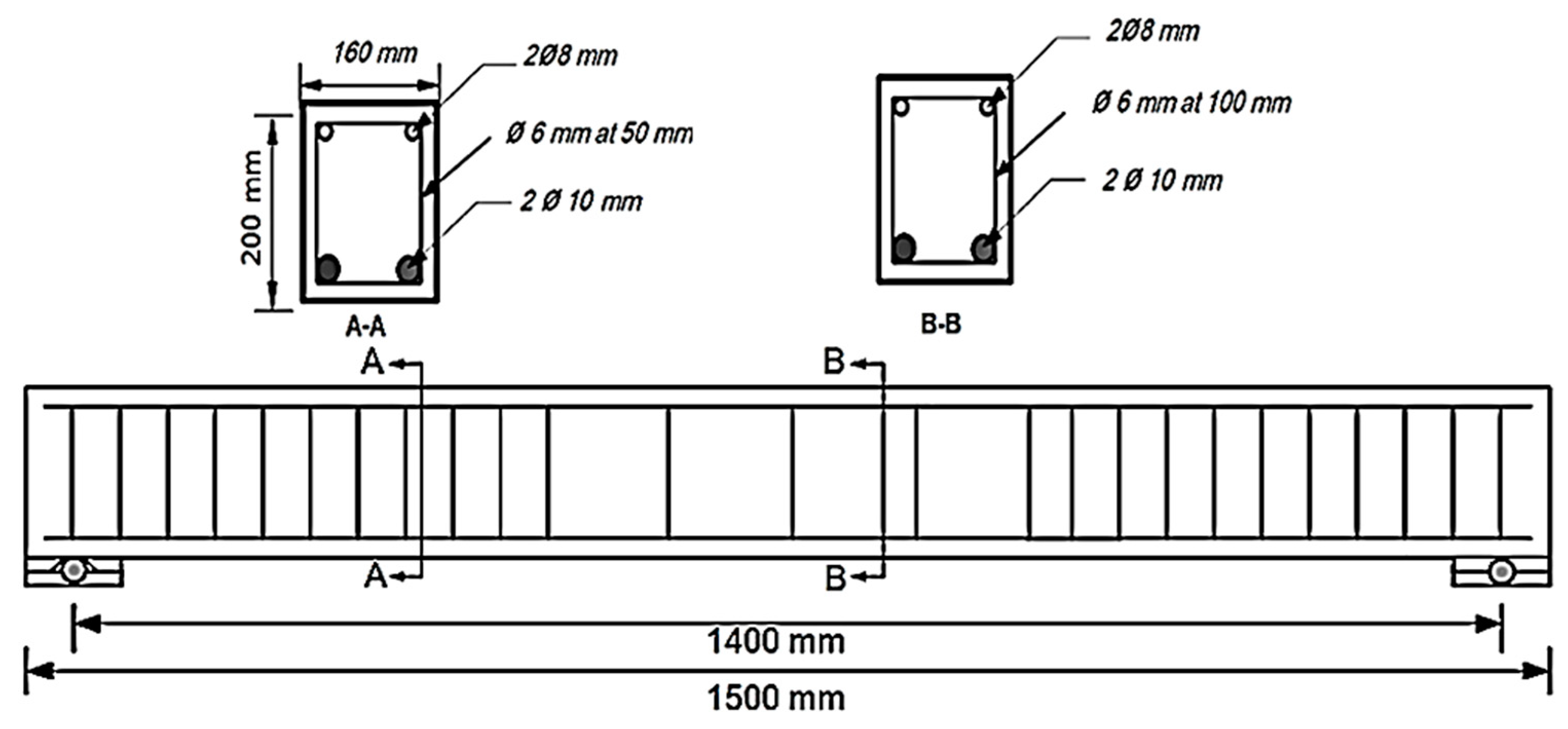
The experimental work was conducted in the structural laboratory of the civil engineering department of Al-Qadisiyah University. Ten RC beam-column members with a dimension of 160 × 200 × 1500 mm were tested under constant axial force and four-point transverse load up to failure. The reinforcement details of beam-column members are shown in Figure 1. Two deformed bars with 10 mm diameters and two other bars with 8 mm diameters were used for longitudinal tension and compression reinforcement, respectively. For stirrups, a 6 mm diameter was used at a spacing of 50 mm, except the middle third span of the member, where the spacing used was 100 mm. The clear concrete cover was 20 mm on all sides of the specimen. The experimental study consisted of two test groups, as illustrated in Table 1. Group (A) included the control (undamaged) specimen, the corrosion-damaged specimens under low or high corrosion levels of 5% or 20%, respectively, and the damaged/patch-rehabilitated specimens that underwent cleaning or replacement of corroded steel bars and repaired the damaged concrete cover with new mortar. These specimens were tested under an axial force of 15 kN in addition to the transverse applied load. Group (B) included the same set of specimens but with an axial force of 30 kN.
2.2. Material Properties
The properties of the main tension bars were recorded as follows: 587 MPa as yield strength, 678 MPa as rupture strength, and 19.4% as elongation. The reinforcement bars elastic modulus was assumed to be 2 × 10⁵ MPa. A mechanical concrete mixture machine was used to produce normal strength concrete for RC beam-column members, and all these members were cast at the same time and had the same concrete quality. The calculated concrete compressive strength was 35 MPa based on cubic tests. The repair materials used in this study were from Sika productions as Sika Mono Top-614 and Sikadur-32. The first one, a one-component modified cementitious repair mortar with a compressive strength of 35 MPa, a flexural strength of 10 MPa, and a layer thickness-up to 60 mm- was used for the damaged concrete repair. The second one, two-components, solvent-free was used as a bonding agent in mortar or steel. Sikadur-32 properties are easy to apply, solvent-free, unaffected by moisture (corrosion protection), and have a high tensile strength 18-20 MPa and high bond strength to concrete of 3 MPa. They were used in this study to compensate for the decrease in bond strength of the corroded steel bars and as bonding agents between old concrete and new mortar.
2.3. Accelerated Corrosion Process
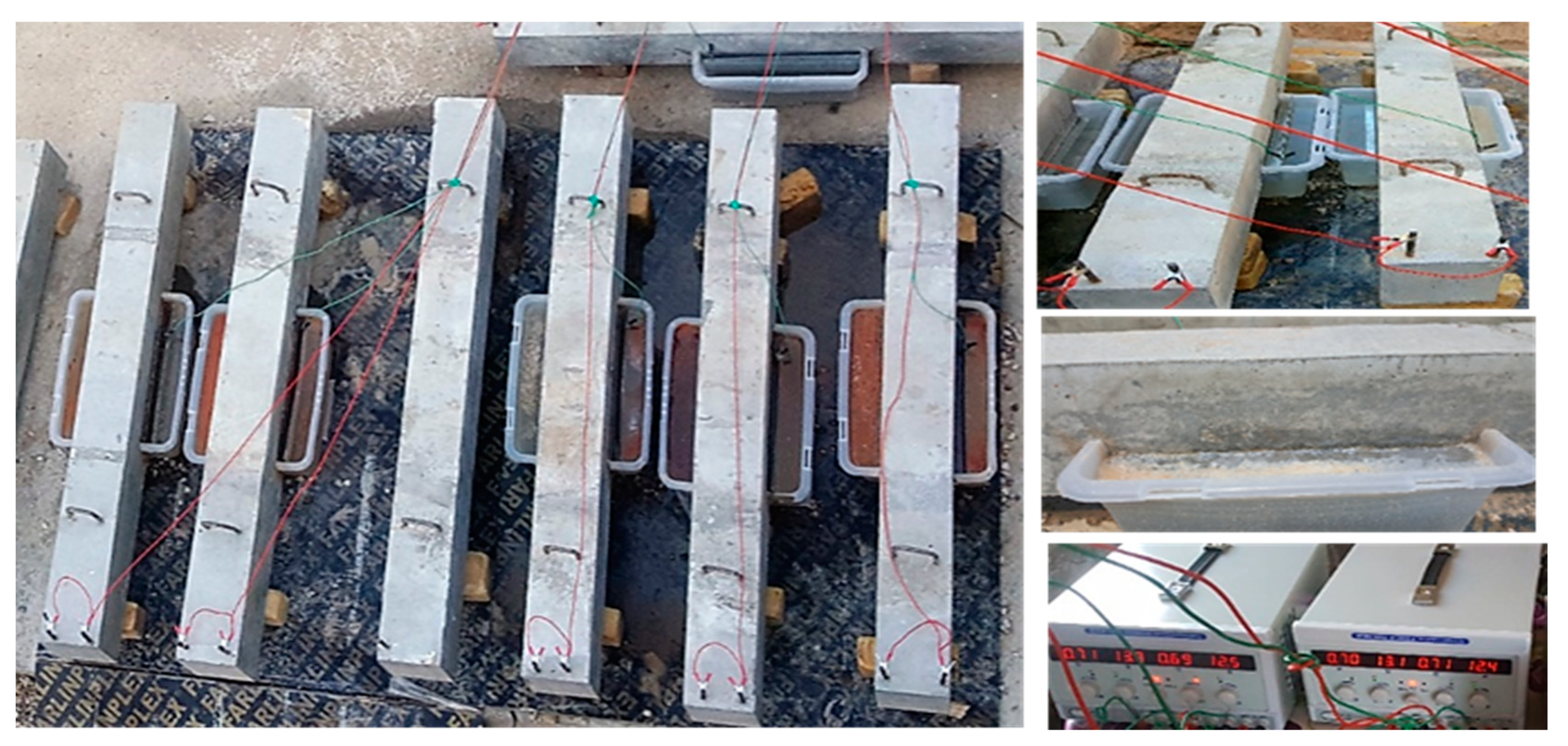
An electrochemical process was used in this study to accelerate the corrosion of steel reinforcement embedded inside the concrete. The corrosion was limited to critical flexural zone with a length, a width, and a height of 400 mm, 160 mm, and 40 mm, respectively. This limited region of the member was submerged in a plastic container with 5% concentrate of sodium chloride solution. Power supplies with adjustable voltage and a direct current (DC) of 700 mA were used for this process. The reinforcement cage was connected to the positive side and the stainless steel plate was connected to the negative side of the DC power supply. The desired degrees of corrosion were 5%, and 20% of the deformed bars, which could occur in a period of 8 and 32 days, respectively according to Faraday’s law. The theoretical mass of rust produced per unit of surface area could be determined based on Faraday’s law, as illustrated in Equation (1).
The actual mass of rust per unit of surface area was determined by a gravimetric test in accordance with ASTM G1 [20], as illustrated in Equation (2).
The degree of induced corrosion was also expressed in terms of the percentage mass loss (ρ) calculated as shown in Equation (3).
The equivalent corrosion current density (Icorr.) could be determined by equating Equation (1) and Equation (2), assuming that the theoretical mass and the actual mass of rust was equal (i.e., Iapp. = Icorr.), as
where represents an electrical current applied (Amp/cm2, is the degree of corrosion (%), is the initial mass of corroded bars (g), is Faraday’s constant (F = 96,500 Amp × Sec), is the original diameter of corroded bars (cm), is the length of corroded bars in the corrosion region (cm), is the equivalent weight of reinforcing steel, which represents the atomic weight of the iron element (Fe) to its equivalent weight (W = 27.925 g).
Equation (4) represents the simplified Faraday’s law formula and was used for calculating the time required to get the t desired degrees of corrosion. Figure 2 shows the experimental setup of the accelerated corrosion process.
2.4. Patch Repair Technique
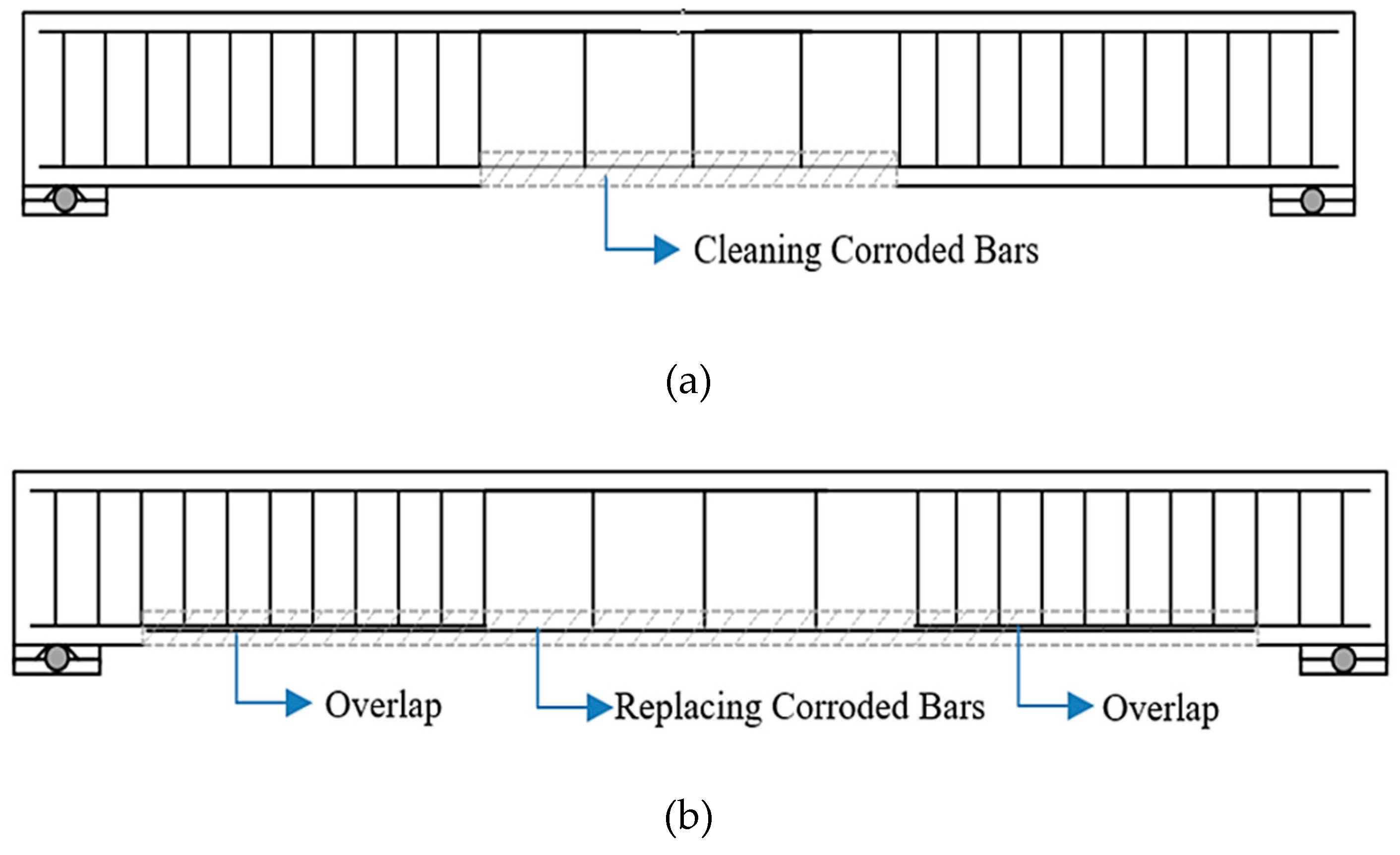
The rehabilitation technique used in this study was patch repair by cleaning or replacing the corroded steel bars and repairing the damaged concrete with new mortar. Firstly, we removed the damaged concrete using manual and mechanical methods. An angle grinder, a claw hammer, and a chisel were used to remove the defective concrete. Secondly, we cleaned the remaining undamaged concrete surface by using an air blower; this stage was very important to get strong substrate. Thirdly, we evaluated the damage in steel reinforcement due to corrosion. For the low corrosion level of 5%, the steel bars were cleaned from rust by a drill motor with a brush, as illustrated in Figure 3a. For the high corrosion level of 20%, the corroded part of the steel bar was cut and removed, then replaced by a new steel bar of the same diameter with consideration to the overlap length, as illustrated in Figure 3b. Fourthly, the sikadur-32 bonding agent and the protection material from the corrosion were used to provide a bond between the existing concrete and the new mortar in addition to the bond between steel bars and the mortar. Finally, sikamonotop-614 (polymer modified repair mortar) was used to replace the damaged concrete layer. Good curing for the mortar was used to prevent shrinkage. Figure 3 shows the sketch of the patch repair technique by cleaning or replacing the corroded steel bars.
2.5. Test Setup
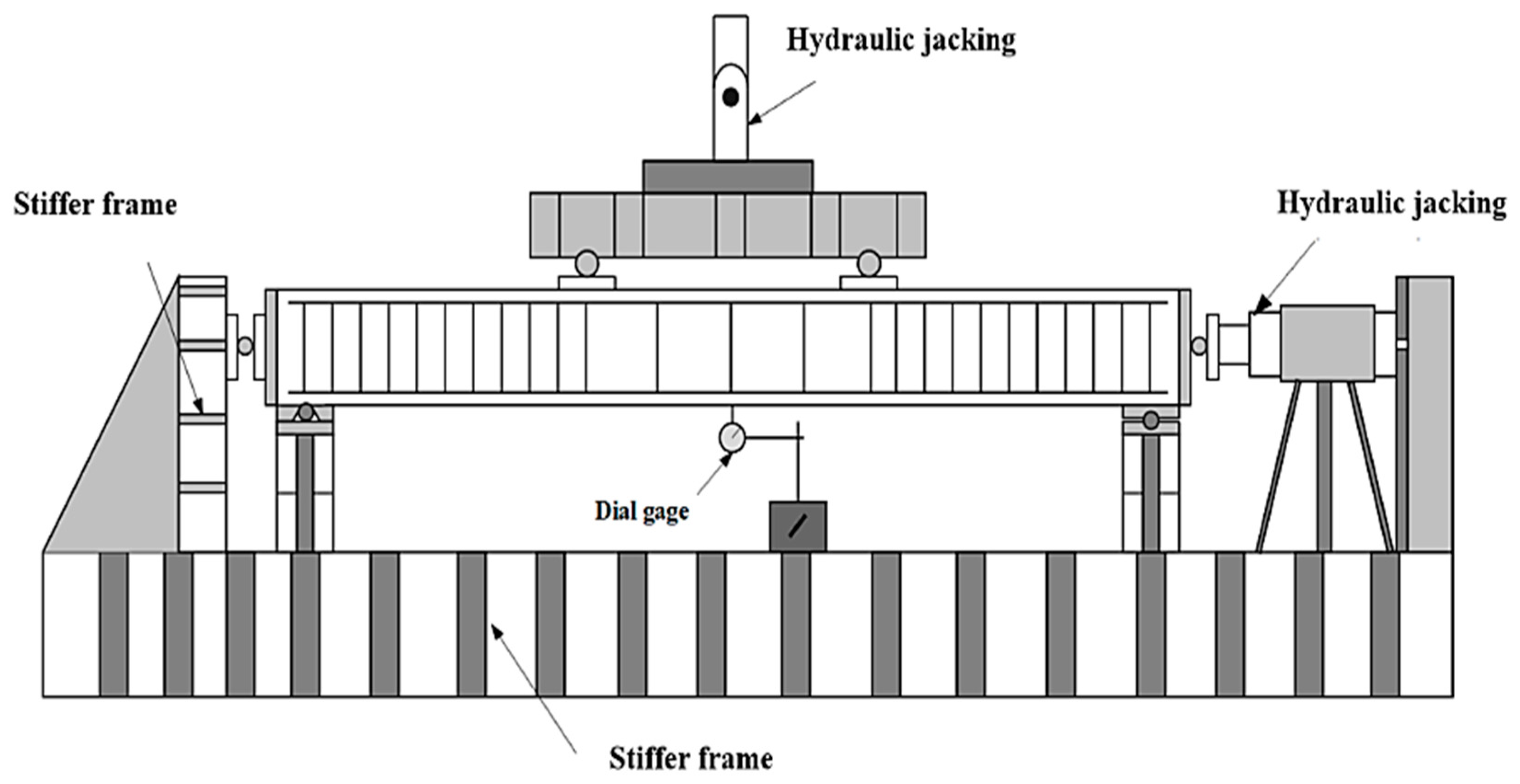
A flexural test was performed for each beam-column member supported over a span of 1400 mm and under constant axial force in addition to four-point transverse load up to failure. After the accelerated corrosion process and the patch repair technique, all specimens were painted with a white color to observe the crack development and marking. A steel frame with a hydraulic jack of 60-ton capacity was used in this study. A necessary modification to this frame was made by strengthening the lower horizontal part of the frame and fixing a new supporting frame with a new hydraulic system and new hydraulic cylinder (700 bar, 500 kN maximum force) capacity, for axial force, as shown in Figure 4. During each load step the corresponding central vertical deflection, the crack patterns, and the ultimate capacity were recorded. A digital image correlation (DIC) with high quality digital camera (Nikon D7100, 24.1 Megapixel) and a computer program called GOM Correlate version 2017 were used to measure concrete strain.
3. Experimental Results and Discussion
3.1. Actual Degree of Corrosion
Low level (5%) and high level (20%) corrosion degrees were considered in this study. To calculate the actual degree of corrosion, we followed the steps of the ASTM G1. After testing all beam-column members, the corroded reinforcement bars were cut and extracted from the limited region of corrosion. Then, they were cleaned and re-weighted without any dust. The actual corrosion degree was calculated based on Equation (5):
where is the initial mass of the non-corroded bars (g) and Wf is the mass of the corroded bars after cleaning the rust (g). The exact masses of the original and the corroded (after cleaning) steel bars with the same lengths were measured, then the degrees of corrosion were calculated from Equation (5), as illustrated in Table 2, and were found to be 5.5% and 20.7% at 8 days and 32 days, respectively. This level of corrosion was close to the predicted corrosion from Faraday’s law.
3.2. Load-Deflection Response and Cracking Pattern
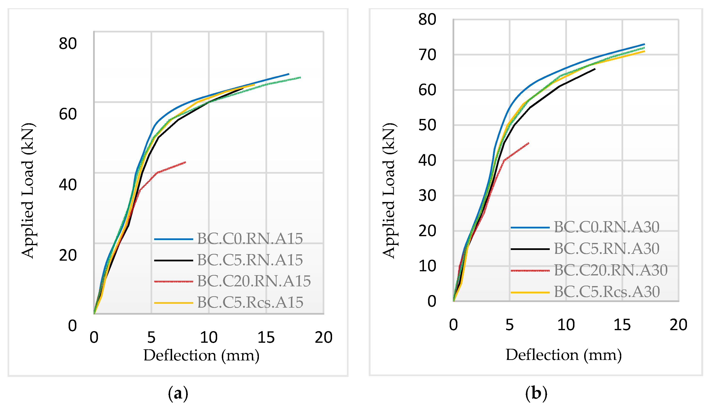
At the early stages of loading, reinforced concrete beam-column specimens were free from any cracks, except the corroded specimens that contained horizontal cracks due to corrosion. The amount of displacement was very small because the stresses resulting from the applied loads were small at this stage of loading. With an increase in the transverse applied load, the cracks began to appear. The experimental results of the ultimate load and the service mid-span deflection for the tested specimens are illustrated in Table 3. A comparison of the load-deflection responses for each group is given in Figure 5.
3.2.1. Specimens in Group A
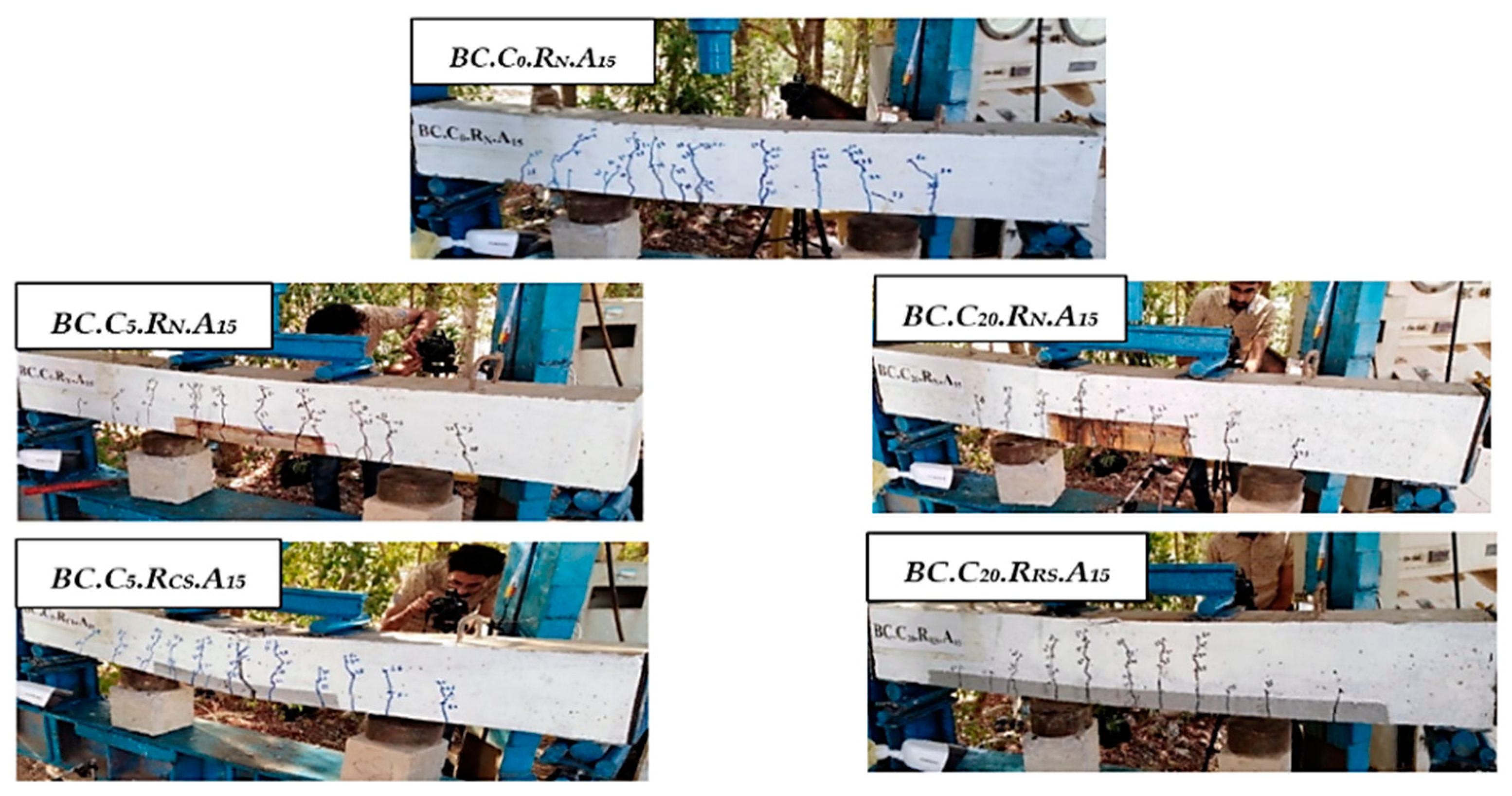
Five specimens (BC.C0.RN.A15, BC.C5.RN.A15, BC.C20.RN.A15, BC.C5.RCS.A15, and BC.C20.RRS.A15, as shown in Figure 6) were tested under a constant axial force of 15 kN, and we gradually applied transverse load up to failure. Horizontal corrosion cracks were appearing before testing due to internal pressure from the corrosion product. First, flexural cracks appeared in the middle third span of the tension face and started to propagate and widen. Then, inclined flexural shear cracks were shown. A flexural yielding followed by a concrete crushing failure occurred for all specimens in this group except one defected specimen with high corrosion level, which failed prematurely failure due to a rupture in the corroded bars. A significant reduction in the ultimate flexural strength and the serviceability was recorded with an increased level of corrosion degrees in addition to a lower stiffness in all stages of load-deflection response. The load-carrying capacity of defected/rehabilitated specimens was restored to about 95.5% after cleaning steel bars and to 98.5% after replacing steel bars with respect to the control specimen. Serviceability in terms of mid-span deflection was restored to the allowable limit of American concrete institute (ACI) code.
3.2.2. Specimens in Group B
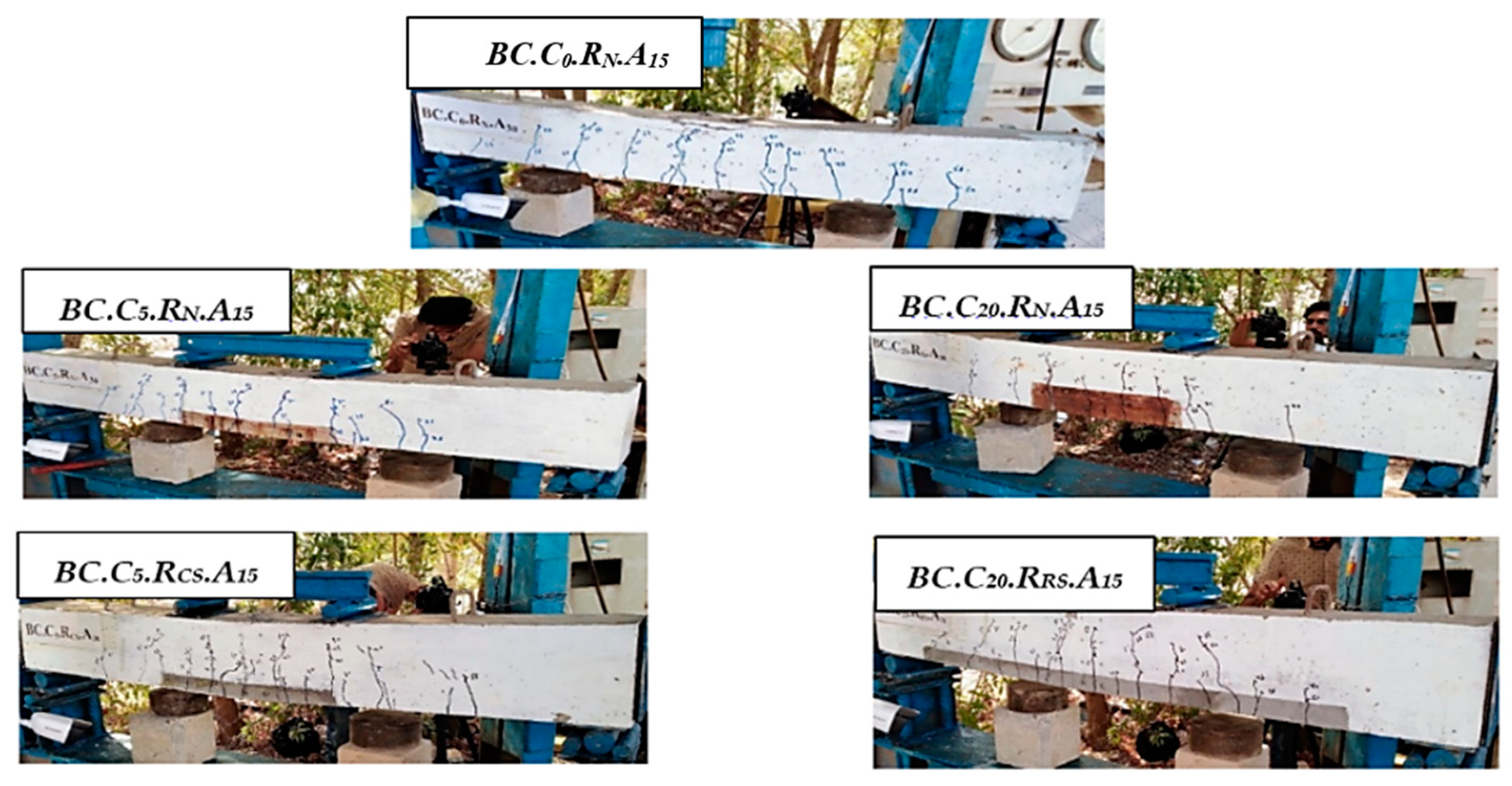
Five specimens (illustrated in Figure 7) were tested under a constant axial force of 30 kN, and we gradually applied transverse loading up to failure. The crack patterns were similar to those of the previous group with more propagation of flexural crack. A flexural yielding followed by concrete crushing failure occurred for all specimens in this group except one defected specimen with high corrosion level, which failed prematurely due to a rupture in the corroded bars. A significant reduction in ultimate strength and serviceability was calculated with increased corrosion degrees in addition to lower stiffness in all stages of the load-deflection response. The load-carrying capacity of deteriorated specimens was restored to about 97.3% after cleaning steel bars and to 98.6% after replacing the steel bars with respect to the control specimen. In addition, serviceability in terms of mid-span deflection was restored to the allowable limit of the ACI (American Concrete Institute) code. Compared with the specimens in Group A, the increase of the axial force was recorded to be a positive effect on the ultimate strength, the service deflection and the stiffness, and this effect was evident in the corrosion-defected specimens by decreasing the adverse effect of corrosion.
3.3. Concrete Strain
An optical method using DIC was used for measuring concrete strain. It is a method that uses a mathematical correlation analysis to examine digital image data taken while samples are in mechanical tests. This technique involves capturing consecutive images with a digital camera during the deformation period to evaluate the change in surface characteristics and understand the response of the specimen while it is subjected to incremental loads. The method begins with a picture before loading (reference image), and then a series of pictures are taken during the deformation process (deformed images). The digital image correlation requires computer software and an appropriate digital camera. In this study, a computer program called “GOM Correlate” version 2017 was used to calculate the concrete strain on the side face and along the depth of the mid span member by calculating the differences between images by relating all pixels in the reference image with each of the distorted images, ultimately achieving a distorted map distribution point.
3.3.1. Specimens in Group A
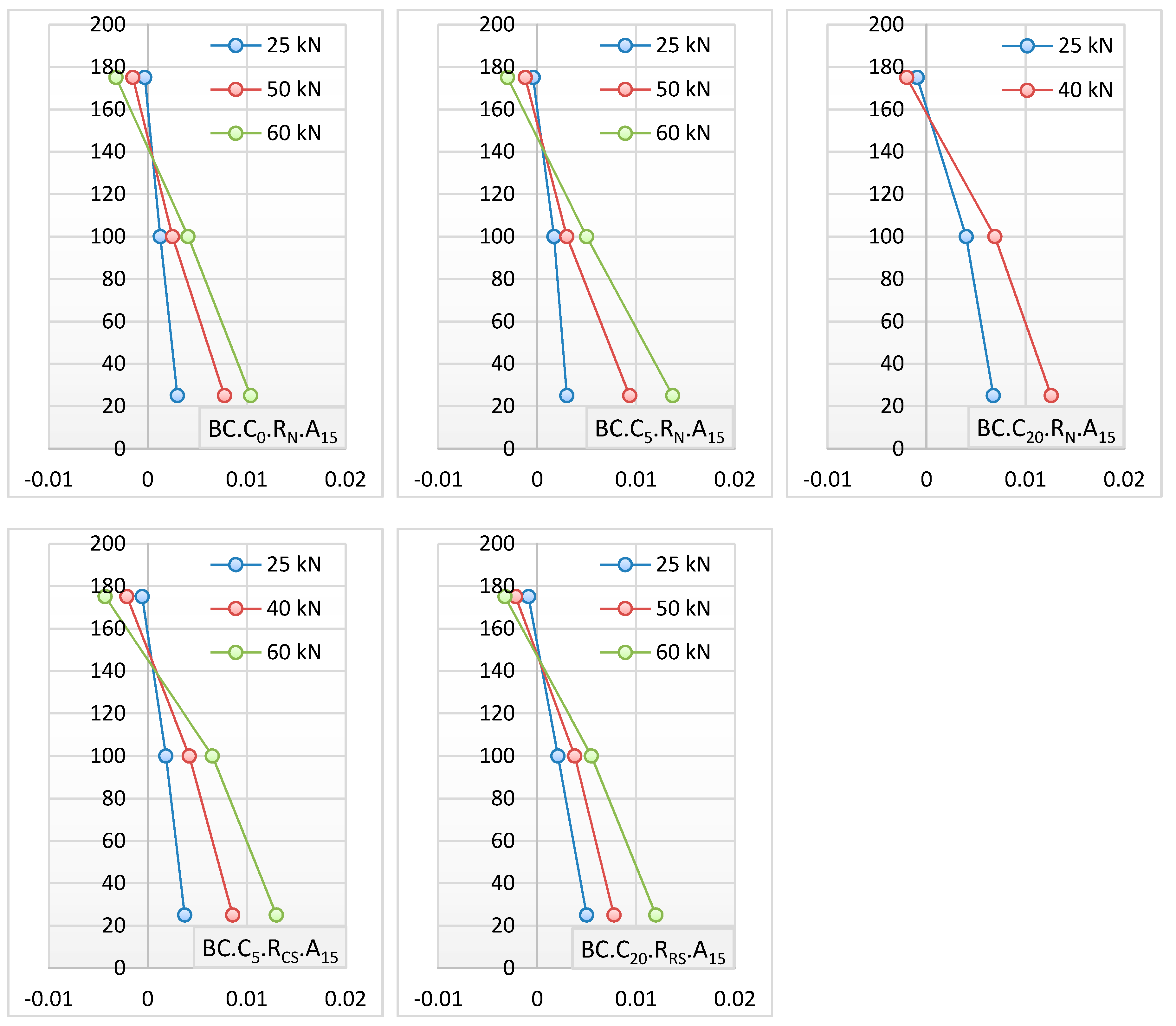
The concrete strain for these specimens was measured at three points through the depth of the mid span of the critical section (maximum moment). The concrete strain was recorded in different loading stages, as shown in Figure 8, where the horizontal and vertical axes represent the concrete strain and the section depth, respectively.
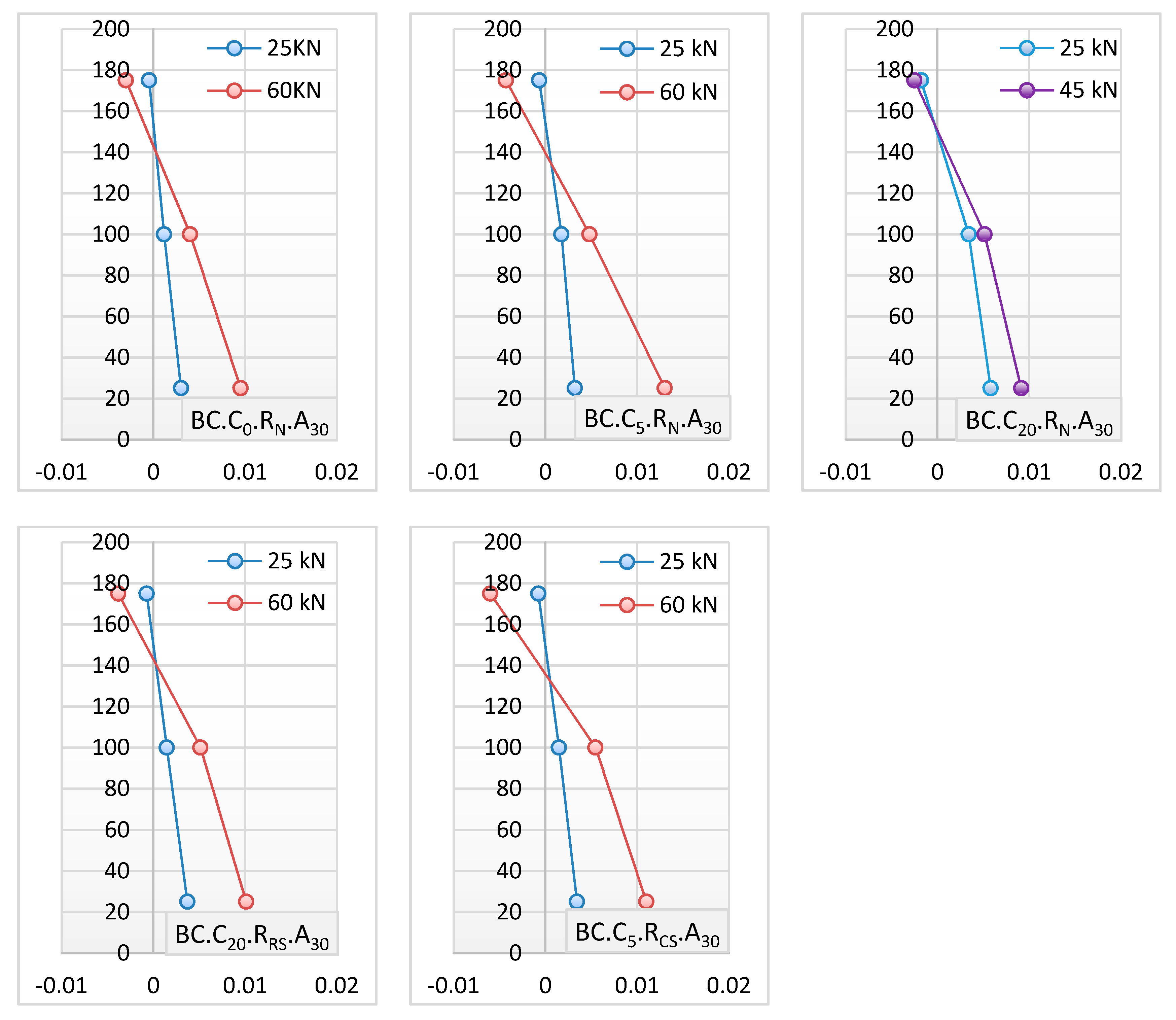
The results of concrete strain for the tested specimens showed that the strain distribution was approximately linear at low loads and became nonlinear at higher loads due to cracks in the concrete. The concrete strain in the tension zone for the corrosion-defected specimen increased clearly with corrosion levels compared to the control specimen due to the reduction in steel-concrete bond strength. For the defected/rehabilitated specimen with a patch repair of cleaning steel bars, the test results recorded a slightly restored concrete strain in the tension zone compared with the defected specimens due to the replacement of the damaged concrete cover with new mortar, the cleaning of the steel bars, and the use of the bonding agent material to compensate the reduction in bond strength. The defected/rehabilitated specimen with a patch repair of replacing steel bars recorded a completely restored concrete strain in the tension zone to an undamaged state. This was achieved by replacing the damaged concrete cover with new mortar, replacing the corroded steel bars and using the bonding agent material to compensate the reduction in bond strength.
3.3.2. Specimens in Group B
Furthermore, the concrete strain for these specimens was recorded through section depth with three points in the mid span of the specimens, as illustrated Figure 9.
3.4. Ductility
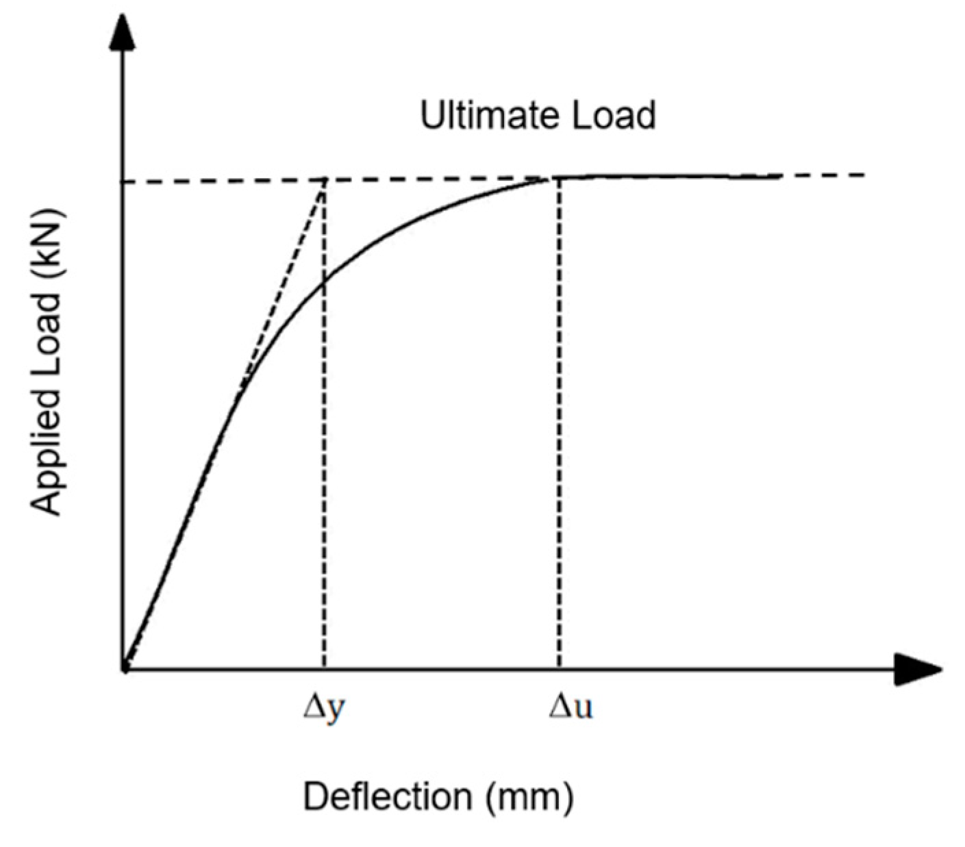
Ductility is described as the ability of a structural element to sustain inelastic deformation without significant loss in resistance [22]. Safety is the most important consideration for the design of structures. Any type of brittle failure should be avoided, since this could limit the warning time and cause lives to be endangered. If the structure possesses ductile behavior, it will be able to experience large deflections while still holding near ultimate loads. Ductility has generally been measured by a ratio called a ductility index or factor (). The experimental ductility index for concrete beam-column members (control or patch repair) specimens was calculated according to the deflection at the ultimate load divided by the deflection at the equivalent yield load [23], as shown in Figure 10.
The ductility results in Table 4 display, a significant decrease in the ductility of the defected specimens compared with the control. More decrease was recorded with high corrosion levels due to the reduction of tensile strength and ductility of the steel bars. This was caused by the reduction in diameter of the corroded steel bars and the reduction in bond strength, which was due to the rust effect on the nature of the deformed surface of the corroded steel bars. For patch repair by cleaning steel bars, a slight increase in ductility was noticed compared with the corresponding defected specimens. In the case of patch repair by replacing steel bars, a significant increase in ductility was noticed compared with the corresponding defected specimens, and these were restored to an undamaged state by using a new steel reinforcement. The effect of increased axial force on ductility was recorded for the control, the defected, and the defected/rehabilitated specimens.
4. Conclusions
The main conclusions obtained from our experimental results are as follows:
- After a period eight days and thirty-two days of accelerated corrosion, real corrosion degrees of 5.5% and 20.7%, respectively, were evidenced, thus the predicted corrosion level of Faraday’s law was suitable to find the corrosion period in the reinforced concrete under accelerated corrosion.
- Significant deteriorations in the ultimate strength, the serviceability and the ductility were recorded due to the reduction in the mechanical properties of corroded steel bars, such as a reduction in the tensile strength, the bond strength, and the ductility.
- Compared with the control specimens, there were significant reductions 6%, and 4% in the ultimate flexural capacities for low corrosion levels and reductions of 37%, and 34% for high corrosion levels under axial forces of 15 kN, and 30 kN, respectively.
- A significant deterioration in the serviceability limit state in terms of mid span deflection was recorded and exceeded the allowable limit of the ACI code.
- A significant deterioration in the ductility was recorded, thus the ductility for specimens with low corrosion levels was decreased by about 19% and 15%; for specimens with high corrosion levels, the ductility was decreased by about 42% and 33%, compared with the control specimens subjected under 15 kN and 30 kN of axial force, respectively.
- When applying patch repair techniques on the defected specimens, the problem of corrosion reinforcement could be overcome with different levels of efficiency, which then enabled the restoration of the structural integrity.
- By applying patch repair by cleaning steel bars for a specimen with a low-corrosion degree, a significant amount of the load-bearing capacity could be restored.
- Patch repair by replacing steel bars for a specimen with a high-corrosion degree almost completely restored the load-carrying capacity.
- Serviceability of the defected/rehabilitated steel bars after patch repair by cleaning or replacing was restored to the allowable limit of ACI code.
- The concrete strain and the ductility were restored to undamaged states when using a patch repair by replacing corroded steel bars.
- The increase of the axial force for the defected specimens was shown to reduce the adverse effects of corrosion in regard to ultimate strength, stiffness, serviceability, and ductility of RC beam-column members.
Author Contributions
Conceptualization, N.A.A., M.M.K. and A.M.M.; methodology, A.M.M.; software, N.A.A. and M.M.K.; validation, N.A.A., M.M.K. and A.M.M.; formal analysis, A.M.M.; investigation, A.M.M.; resources, A.M.M.; data curation, A.M.M.; writing—original draft preparation, A.M.M.; writing—review and editing, N.A.A., M.M.K. and A.M.M.; visualization, A.M.M.; supervision, N.A.A. and M.M.K.; project administration, A.M.M.; funding acquisition, A.M.M.
Funding
This research received no external funding.
Acknowledgments
The authors are thankful to all staff members of Civil Engineering Department and Electrical Engineering Department/College of Engineering/University of Babylon in addition to Civil Engineering Department/University of Al-Qadisiyah for their facilities and assistance throughout this study.
Conflicts of Interest
The authors declare no conflicts of interest.
References
- Al-Sulaimani, G.J.; Kaleemullah, M.; Bassunbul, I.A.; Rasheeduzzafar. Influence of corrosion and cracking on bond behavior and strength of reinforced concrete members. ACI Struct. J. 1990, 87, 220–231. [Google Scholar]
- Central Public Works Department Group. Rehabilitation and Retrofitting Methods, 1st ed.; Director General (Works), Central Public Works Department, Government of India, Nirman Bhawan: New Delhi, India, 2002; pp. 1–31.
- Mahmud, S.; Samdani, A. Effect of building shape on the response to wind and earthquake. Int. J. Adv. Struct. Geotech. Eng. 2015, 4, 232–236. [Google Scholar]
- Abdullah, A.A. Test model for the first Canadian smart highway bridge. Constr. Build. Mater. 2001, 15, 361–368. [Google Scholar]
- Mangat, P.S.; Elgarf, M.S. Flexural Strength of concrete beams with corroding reinforcement. ACI Struct. J. 1999, 96, 149–158. [Google Scholar]
- Carlos, G.B.; Karin, L.; Ingemar, L. Investigation on the influence of fiber reinforcement on chloride induced corrosion of RC structures. In Proceedings of the 11th Fib International Ph.D. Symposium in Civil Engineering, Tokyo, Japan, 29–31 August 2016. [Google Scholar]
- Ballim, Y.; Reid, J.C. Reinforcement corrosion and the deflection of RC beams-an experimental critique of current test methods. Cem. Concr. Compos. J. 2003, 25, 625–632. [Google Scholar] [CrossRef]
- Goitseone, M.; Mark, A.; Pilate, M. Variation of steel loss and its effect on the ultimate flexural capacity of RC beams corroded and repaired under load. Constr. Build. Mater. 2010, 24, 1051–1059. [Google Scholar]
- Gu, X.L.; Zhang, W.P.; Shang, D.F. Flexural Behavior of Corroded Reinforced Concrete Beams. In Proceedings of the 12th Biennial International Conference on Engineering, Construction, and Operations in Challenging Environments, Honolulu, HI, USA, 14–17 March 2010. [Google Scholar]
- Zhu, W.; François, R.; Coronelli, D.; Cleland, D. Effect of corrosion of reinforcement on the mechanical behaviour of highly corroded RC beams. Eng. Struct. J. 2013, 56, 544–554. [Google Scholar]
- Torres-Acosta, A.; Fabela-Gallegos, M.; Munoz-Noval, A.; Vazquez-Vega, D.; Hernandez-Jimenez, T.; Martinez-Madrid, M. Influence of corrosion on the structural performance of reinforced concrete beams. Corrosion 2004, 60, 862–872. [Google Scholar] [CrossRef]
- Ma, Y.; Guo, Z.; Wang, L.; Zhang, J. Experimental investigation of corrosion effect on bond behavior between reinforcing bar and concrete. Constr. Build. Mater. 2017, 152, 240–249. [Google Scholar] [CrossRef]
- Hou, L.; Guo, S.; Zhou, B.; Chen, D.; Aslani, F. Bond-slip behavior of corroded reinforcement and ultra-high toughness cementitious composite in flexural members. Constr. Build. Mater. 2019, 196, 185–194. [Google Scholar]
- Niloufar, G.; Amir, M.; Mohammad, S. Flexural behavior of post tensioned beams damaged by reinforcement corrosion before and after applying patch-repair. Am. J. Civ. Eng. Archit. 2016, 4, 171–180. [Google Scholar]
- Garyfalia, T.; Theodoros, R.; Athanasios, K. Corroded RC beams at service load before and after patch repair and strengthening with NSM CFRP strips. Buildings 2019, 9, 67. [Google Scholar]
- Al-Saidy, A.H.; Al-Jabri, K.S. Effect of damaged concrete cover on the behavior of corroded concrete beams repaired with CFRP sheets. Compos. Struct. 2011, 93, 1775–1786. [Google Scholar] [CrossRef]
- Almassri, B.; Amjad, K.; Al Mahmoud, F.; François, R. Mechanical behaviour of corroded RC beams strengthened by NSM CFRP rods. Compos. J. Part B 2014, 64, 97–107. [Google Scholar] [CrossRef]
- Haddad, R.H. Hybrid repair configurations with CFRP composites for recovering structural performance of steel-corroded beams. Constr. Build. Mater. 2016, 124, 508–518. [Google Scholar]
- Zhang, H.; Wu, J.; Jin, F.; Zhang, C. Effect of corroded tension reinforcements on flexural performance of reinforced recycled aggregate concrete beams strengthened with CFRP. J. Compos. Part B 2019, 162, 589–599. [Google Scholar]
- ASTM G1. Standard Practice for Preparing, Cleaning, and Evaluating Corrosion Test Specimens; American Society for Testing and Materials: West Conshohocken, PA, USA, 2003. [Google Scholar]
- ACI Committee 318-14. Building Code Requirements for Structural Concrete; American Concrete Institute: Farmington Hills, MI, USA, 2014. [Google Scholar]
- Newman, J.; Choo, B.S. Advanced Concrete Technology, 1st ed.; Elsevier Ltd.: London, UK, 1986; p. 616. [Google Scholar]
- Park, R.; Paulay, T. Reinforced Concrete Structures; John Wiley: New York, NY, USA, 1975; p. 769. [Google Scholar]
Figure 1.
Concrete geometry and reinforcement details of tested specimen.

Figure 2.
Acceleration corrosion process.

Figure 3.
Detail of the patch repair technique. (a) patch repair by cleaning corroded steel bars; (b) Patch repair by replacing corroded steel bars.
Figure 3.
Detail of the patch repair technique. (a) patch repair by cleaning corroded steel bars; (b) Patch repair by replacing corroded steel bars.

Figure 4.
Sketch of modified testing machine.

Figure 5.
Comparison of load deflection response for each group. (a) Group A; (b) Group B.

Figure 6.
Cracks pattern and mode of failure of specimens in Group A.

Figure 7.
Cracking patterns at failure for specimens in Group B.

Figure 8.
Concrete strain for specimens in Group A.

Figure 9.
Concrete strain for specimens in Group B.

Figure 10.
Determination procedure of the ductility index.


Table 1.
Designation and details of tested specimens.
| Groups | Symbol of * Specimens | Degree of Corrosion (%) | Rehabilitation Technique | Axial Force (kN) |
|---|---|---|---|---|
| A | BC.C0.RN.A15 | 0 | Non | 15 |
| BC.C5.RN.A15 | 5 | Non | 15 | |
| BC.C20.RN.A15 | 20 | Non | 15 | |
| BC.C5.RCS.A15 | 5 | cleaning corroded bars | 15 | |
| BC.C20.RRS.A15 | 20 | replacing corroded bars | 15 | |
| B | BC.C0.RN.A30 | 0 | Non | 30 |
| BC.C5.RN.A30 | 5 | Non | 30 | |
| BC.C20.RN.A30 | 20 | Non | 30 | |
| BC.C5.RCS.A30 | 5 | cleaning corroded bars | 30 | |
| BC.C20.RRS.A30 | 20 | replacing corroded bars | 30 |
* Where: BC stands for beam-column, Ca stands for degree of corrosion (5% or 20%), Rb stands for rehabilitation technique, CS stands for cleaning steel, RS stands for replacing steel, and Ac stands for axial force (either 15 kN or 30 kN).
Table 2.
Desired and actual degree of corrosion of corroded steel bars.
| Initial Mass of Non-Corroded Bar Wi, (g) | Final Mass of Corroded Bar Wf, (g) | Desired Degree of Corrosion (%) | Actual Degree of Corrosion CD, (%) |
|---|---|---|---|
| 270 | 255 | 5 | 5.5 |
| 270 | 214 | 20 | 20.7 |
Table 3.
Ultimate load capacity and service deflection for tested specimens.
| Groups | Symbol of Specimens | Degree of Corrosion CD (%) | Ultimate Load PU, kN | Mid-Span Service Deflection, mm | Allowable Deflection ACI-318 [21], mm |
|---|---|---|---|---|---|
| A | BC.C0.RN.A15 | 0 | 68 | 3.6 | 3.9 |
| BC.C5.RN.A15 | 5 | 64 | 4 | 3.9 | |
| BC.C20.RN.A15 | 20 | 43 | 5.1 | 3.9 | |
| BC.C5.RCS.A15 | 5 | 65 | 3.8 | 3.9 | |
| BC.C20.RRS.A15 | 20 | 67 | 3.7 | 3.9 | |
| B | BC.C0.RN.A30 | 0 | 73 | 3.5 | 3.9 |
| BC.C5.RN.A30 | 5 | 70 | 3.9 | 3.9 | |
| BC.C20.RN.A30 | 20 | 48 | 4.5 | 3.9 | |
| BC.C5.RCS.A30 | 5 | 71 | 3.7 | 3.9 | |
| BC.C20.RRS.A30 | 20 | 72 | 3.6 | 3.9 |
Table 4.
Ductility index of tested specimens.
| Groups | Symbol of Specimens | Ultimate Deflection, ∆u (mm) | Yielding Deflection, ∆y (mm) | Ductility Index µduc. (∆u/∆y) |
|---|---|---|---|---|
| A | BC.C0.RN.A15 | 17 | 6.5 | 2.6 |
| BC.C5.RN.A15 | 13 | 6.8 | 2.1 | |
| BC.C20.RN.A15 | 8 | 5.2 | 1.5 | |
| BC.C5.RCS.A15 | 14 | 7 | 2.3 | |
| BC.C20.RRS.A15 | 18 | 6.5 | 2.7 | |
| B | BC.C0.RN.A30 | 16 | 5.9 | 2.7 |
| BC.C5.RN.A30 | 16 | 7 | 2.3 | |
| BC.C20.RN.A30 | 10 | 5.5 | 1.8 | |
| BC.C5.RCS.A30 | 17 | 7.1 | 2.4 | |
| BC.C20.RRS.A30 | 19 | 6.7 | 2.8 |
© 2019 by the authors. Licensee MDPI, Basel, Switzerland. This article is an open access article distributed under the terms and conditions of the Creative Commons Attribution (CC BY) license (http://creativecommons.org/licenses/by/4.0/).
Share and Cite
MDPI and ACS Style
A. Alwash, N.; M. Kadhum, M.; M. Mahdi, A. Rehabilitation of Corrosion-Defected RC Beam-Column Members Using Patch Repair Technique. Buildings 2019, 9, 120. https://0-doi-org.brum.beds.ac.uk/10.3390/buildings9050120
AMA Style
A. Alwash N, M. Kadhum M, M. Mahdi A. Rehabilitation of Corrosion-Defected RC Beam-Column Members Using Patch Repair Technique. Buildings. 2019; 9(5):120. https://0-doi-org.brum.beds.ac.uk/10.3390/buildings9050120
Chicago/Turabian StyleA. Alwash, Nameer, Mohammed M. Kadhum, and Ahmed M. Mahdi. 2019. "Rehabilitation of Corrosion-Defected RC Beam-Column Members Using Patch Repair Technique" Buildings 9, no. 5: 120. https://0-doi-org.brum.beds.ac.uk/10.3390/buildings9050120
Note that from the first issue of 2016, this journal uses article numbers instead of page numbers. See further details here.