1. Introduction
The design of large, reinforced concrete chimneys is usually based on the assumption of an isolated structure under wind loading. In many power plants with two or more similar chimneys, however, considerable interference effects can be expected, leading to more severe loading [
1,
2,
3]. For a wide range of wind directions, the chimneys will behave similarly to the isolated ones, but their across-wind response can compromise the structural safety of the leeward chimney when they are noticeably in-line [
4,
5]. This effect is due to the turbulence of the oncoming wind and vortices separating from the upwind chimney may induce further dynamic loads. Under these conditions it may be necessary to add structural damping by installing passive control devices (usually pendulum-type TMDs) [
6,
7] whose performance is studied in this paper.
This work evaluates the wind effects on two adjacent chimneys, one of them equipped with TMD, for different wind speeds and directions. Because of their slenderness, both chimneys are accurately modelled using finite beam element formulation. The fluid flow is assumed to be incompressible and its effects are evaluated using a simplified Computational Fluid Dynamics (CFD) technique considering a discrete number of planes orthogonal to the axis of the chimneys. As the main flow acts in the transversal direction, the presence of fluid shear forces causes the Strouhal (
St) number to vary along the chimney length, so the vortex shedding takes place in spanwise cells with constant frequency over each cell [
8,
9,
10,
11]. In this way, based on the fact that vortices are organized in volumetric cells, just a few planes are necessary and the assumption that the flow among neighbouring planes is independent can be made. Of course, the approach completely misses the spanwise correlation and tip effects associated with vortex shedding in atmospheric shear flow, but the aim is not to address the detailed fluid mechanics approach or the FSI procedure, but to address the engineering problem of the wind interference response of the chimneys and the mechanical effects of the TMD.
The main numerical aspects of the computational approach have been presented in [
3,
12], where not only the physical background and solid and fluid modelling are presented, but also fluid-structure coupling techniques are explained and applied to an isolated chimney. The ability to deal with the mass damper assembly was presented in [
13], where comparisons with full-scale data from monitoring were included. In this work, the focus is on a case study in which aeroelastic interference effects between two chimneys lead to a more severe response of the leeward chimney, the mechanical behavior of which is very different depending on the installation of a proper TMD.
Large amplitude vibrations may occur in lightly damped vertical stacks when the frequency of the vortex shedding (ns) is in the range of one of the natural frequencies of the structure. Vortex shedding also generates an along-wind load with a frequency of 2ns. However, as its amplitude is much smaller than the one in the across-wind direction, its effects are usually neglected.
2. Wind-Structure Interaction Numerical Technique
Several 3D beam finite elements are used for modelling the chimney, resulting in the standard matrix system of differential equations:
The finite elements are formulated for thin-walled beams using the Euler-Bernoulli-Vlasov theory [
12].
M is the mass matrix,
K is the stiffness matrix and
C is the viscous damping matrix. The generalized displacement vector
includes, for each node, three translations and rotations and the axial warping. The TMD is simply included in Equation (1) as an additional one-degree-of-freedom system (
m,
c,
k) attached to the corresponding node of one of the beam elements used to model the chimney. The Newmark and Bossak approach [
14,
15] is used to solved Equation (1) after imposing the boundary conditions.
Although other alternatives (analytical or semi-empirical formulations) could be applied, the pressure around the stack is evaluated using CFD. Note that the effects of the dynamic response of this type of vertical structures under wind action are usually classified into along-wind and across-wind effects. The complexity of the across-wind forcing mechanisms have led to a considerable amount of conceptual, theoretical, experimental and numerical research studies. Fundamental results concerning Vortex-Induced Vibrations (VIV) are presented in [
10,
16,
17,
18] and recent advances in CFD techniques have revealed that the effects of along-wind and across-wind loading can be simulated even for high Reynolds flow regimes [
15,
19].
The force vector
is evaluated integrating the pressure field (
p), obtained by CFD, over the circular cross-section in the corresponding fluid plane (located at height
z) Assuming incompressible fluid, the Navier-Stokes equations (Equation (2)) are solved using the procedure presented in [
15].
where
b is the body force and
v the velocity field.
The interest of this paper focuses on the behavior of the stack subjected to a flow orthogonal to its vertical axis
z, under which assumption the fluid domain has been modelled with a number of uncorrelated planes of fluid, where the fluid problem can be solved separately. The solver is based on Variational Multi-Scale techniques, where an Orthogonal Sub-Grid Scale stabilization approach is used, as described in [
20]. Such a stabilization technique can be easily included in the finite element formulation and tends to introduce energy dissipation, acting in a similar way to a turbulence model.
For each fluid plane _z the CFD solution provides the force acting on the beam cross-section, which is obtained by integrating the pressure of the fluid over the boundary of the cross-section. The time-varying force for the rest of the chimney nodes is obtained (at any instant of time) by standard interpolation techniques between consecutive fluid planes once is known in every fluid plane.
Once the force is obtained, the kinematic solution x is given by Equation (1) and the fluid-structure interaction problem can be addressed. Under the usual assumptions, the motion of the beam axis (Oz) describes the motion of the whole cross-section. It should be notices that the ovalization of the chimney windshield is neglected and the cross-section is considered as a rigid contour that follows the translation and the rotation of the beam axis.
The movement of the structure (and the consequent movement of the fluid mesh) provides a kind of correlation between the motion of the different beam nodes and the fluid planes. As a last step, it is necessary to choose a suitable fluid-structure coupling algorithm. The proposal in this study, where the aeroelastic problem is characterized by large Reynolds numbers and then the flow separation around the circular cross-section appears, is to use loose coupling procedures [
15,
19] together with the fractional step procedure and the ALE formulation [
12,
19].
3. Application for the Case of Rugeley Old and New Chimneys
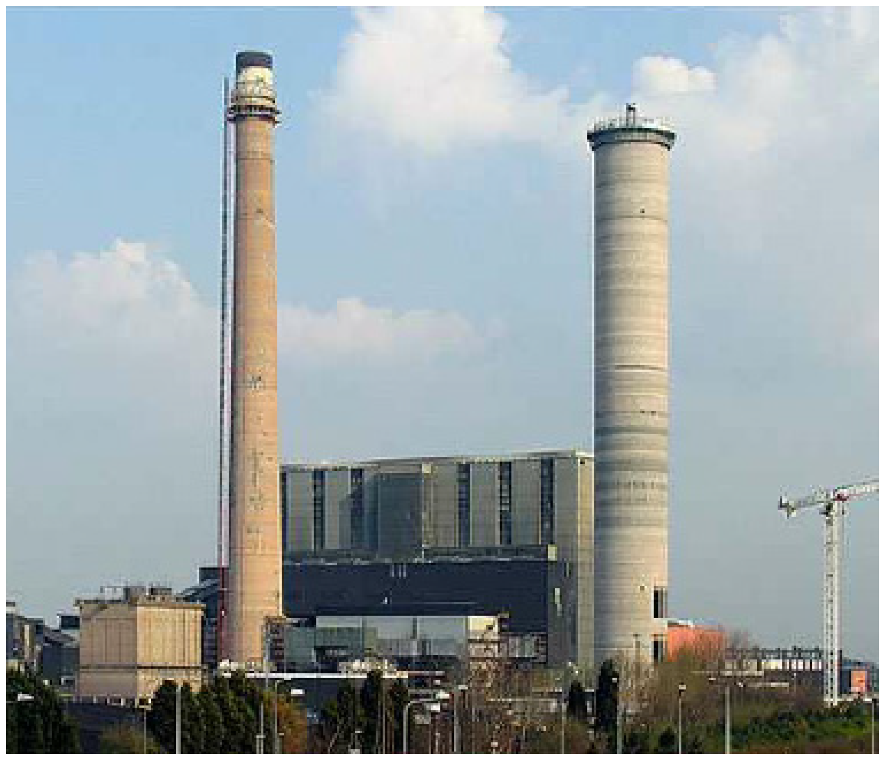
Figure 1 shows the old chimney (left) and the new one (right, under construction) at the Rugeley Power Station (England). The two chimneys coexisted for about two years until the demolition of the old chimney, which consisted of a 183 m reinforced concrete windshield tapered from an external diameter of 9.4 m at the top to 15.7 m at the base. In order to meet environmental requirements, a flue gas desulphurization plant had to be installed, together with a new 183 m chimney in the vicinity of the existing one at a distance of 110 m. In this case, the windshield cross-section was kept constant with a 17 m internal diameter and 0.33 m of wall thickness.
Due to the slenderness of both close stacks, the engineers were concerned about the possibility of interference problems. The report conducted before constructing the new chimney concluded that ‘interference effects associated with the construction of the new chimney would significantly increase loads on the existing chimney’. The study also indicated that the dynamic response of the existing chimney would strongly depend on its damping capacity and that, for wind speeds of about 31 m/s, the response would reach a maximum.
Using wind data from a nearby meteorological station, it was estimated that, with a probability greater than 25%, critical wind speeds would be expected in the direction connecting the new chimney to the old one.
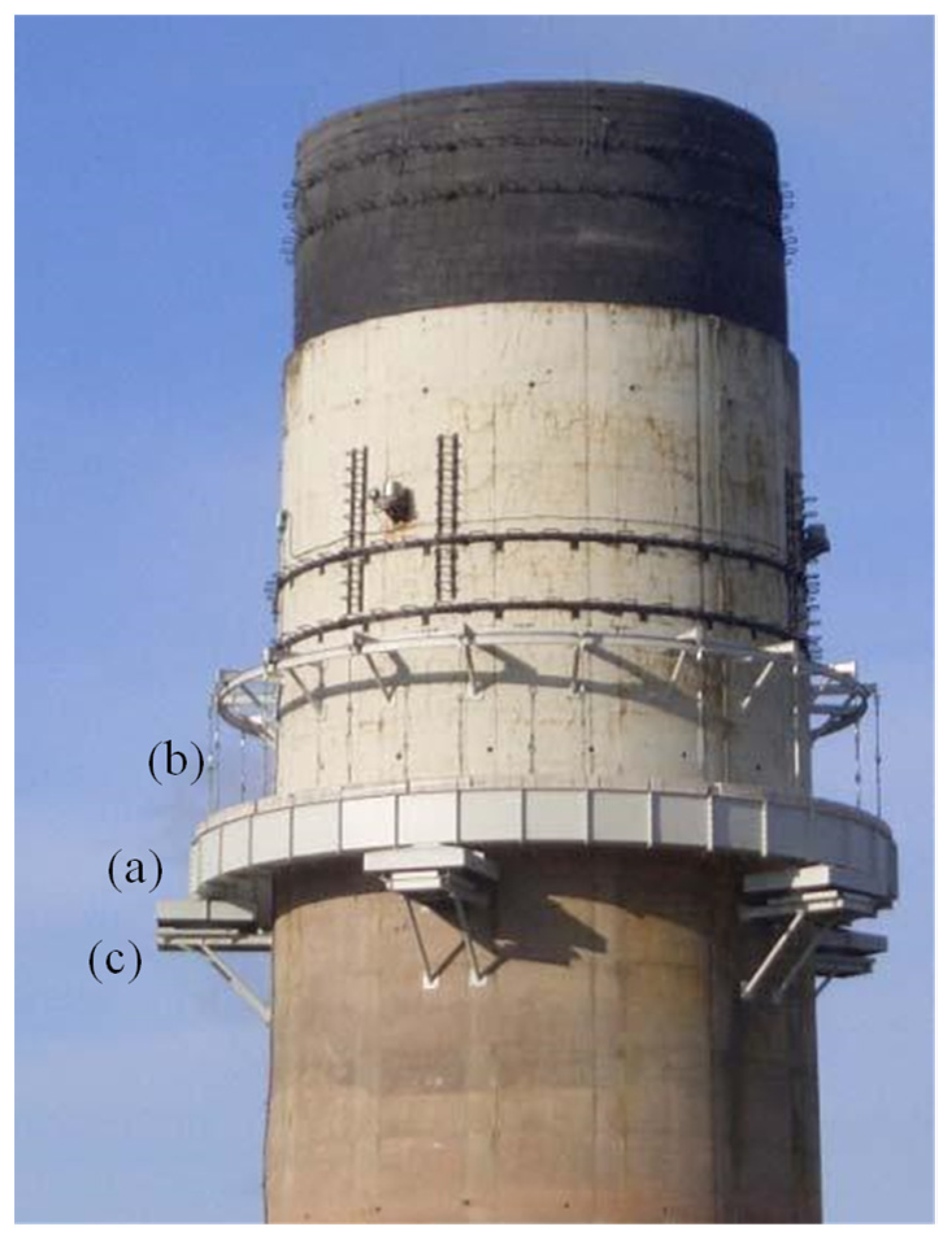
While deciding how to deal with the problem, a permanent monitoring system was installed to estimate some modal parameters (mainly frequencies and damping ratios). Although there were other alternatives to strengthen the existing chimney, it was decided to attach a large TMD in order to increase the damping capacity and reduce the dynamic response below actual chimney capacity. As usual in chimneys [
6], a pendulum type TMD was designed, consisting of a heavy ring (a) hung from multiple suspension cables (b) and equipped with the corresponding viscous dampers (c). See parts in
Figure 2.
The frequencies of the first two modes were calculated using operational modal identification techniques [
13], resulting in 0.338 Hz and 1.40 Hz. First and second mode shapes are the typical ones of a cantilever beam [
6]. Efforts are focused on mitigating the first vibration mode, which presents greater displacements at the top so the TMD must be placed as high as possible. For the first mode, the viscous damping ratio was estimated in 0.7% and the modal mass (at TMD location) was around 1280 tons. The numerical model was properly updated in order to match these experimental data. Being the objective to minimize the stresses and being the stress field proportional to the displacements field, the TMD was designed in terms of receptance.
The receptance [
21] is the relation, in the frequency domain, between the displacement q(w), considered as the output, and the force f(w), considered as the input (Equation (3)),
which is a complex function representing the evolution of the displacement (in magnitude and phase) of some point of the chimney with the input frequency of the wind induced force.
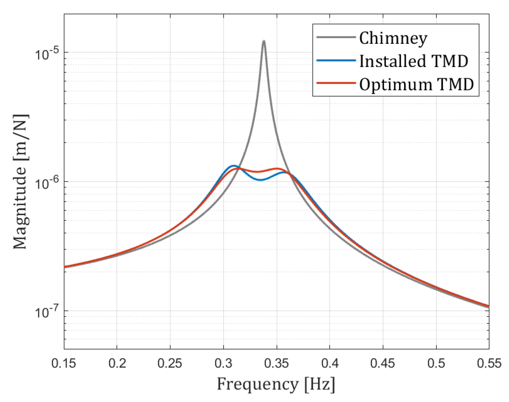
Figure 3 shows in grey the magnitude of the frequency response function (FRF) Equation (3) of the single degree of freedom system (
M,
C,
K) representing the chimney alone. The output (displacement) and input (force) are both at TMD location (autoFRF). The maximum magnitude is 1.237 × 10
−5 m/N.
For the desired response reduction, the system (
m,
c,
k) is attached to the previous one (
M,
C,
K). The mass
m of the TMD was fixed in 42 tons in the design stage, which represents 3.3% of the modal mass
M of the chimney.
m and
c parameters must be found by optimization consisting in minimizing the following cost function J, Equation (4),
where
hT is the receptance of the resulting assembled two degree of freedom mechanical system [
21]. Note that once
m and
k is obtained, the frequency w (and hence the length of the suspension cables
L) are related by Equation (5).
where
g is the acceleration of gravity.
The FRF of the optimum assembled set is shown in red. The magnitude of the twin peaks (at 0.3099 and, 0.3562 Hz) is 1.259 × 10⁻⁶ so the reduction is just the 90%. Because of that, the frequency of the pendulum must be 0.3295 Hz (pendulum length of 2.29 m) and the damping coefficient 18 kNs/m (which leads to 10.35% of viscous damping ratio).
Once manufactured and after a fine-tuning process during installation, the original peak at 0.338 Hz was split into 0.305 Hz and 0.360 Hz. With these experimental data, back into the numerical model (blue line in
Figure 3) the receptance peaks are 1.3264 × 10
−6 and 1.1789 × 10
−6 m/N which means a very good fit (given the challenging installation process) with an improvement of around 89%. The experimental results that will be shown in the following sections correspond to this real situation.
4. Wind Loading Modelling: Fluid Planes and Wind Speeds and Directions
In order to study the structural behavior of the assembly (stack + TMD) under wind loading, two specific wind speeds were selected,
= 7.8 m/s and
= 12.2 m/s, among the available meteorological data (where
stands for the wind speed at 10 m above the ground level), for a specific windy day [
3]. For these wind speeds, the resulting dynamic behaviors recorded by the monitoring system were substantially different. Moreover, those speeds were selected out of the range where interference phenomena may occur. Such wind speeds and directions are considered constant in the time slot selected. Note that the numerical simulation techniques assume that the winds are steady ones.
As stated before, in the proposed numerical approach, the wind is not modelled on the whole volume, its effect being evaluated only in a low number of horizontal planes. The results presented are for the case with just two fluid planes, one located at the tip (denoted as _1) and the other at 122 m (denoted as _2). Both planes are considered representative of a three-dimensional phenomenon of vortex shedding that occurs in the whole chimney [
10,
22]. For a higher number of fluid planes, the quantitative results differ slightly, and the computational effort is greater. In addition, if the location of the planes is different, the results are affected, but not substantially. The usual wind profile power law was taken:
[
5].
5. Assessment of the TMD Performance
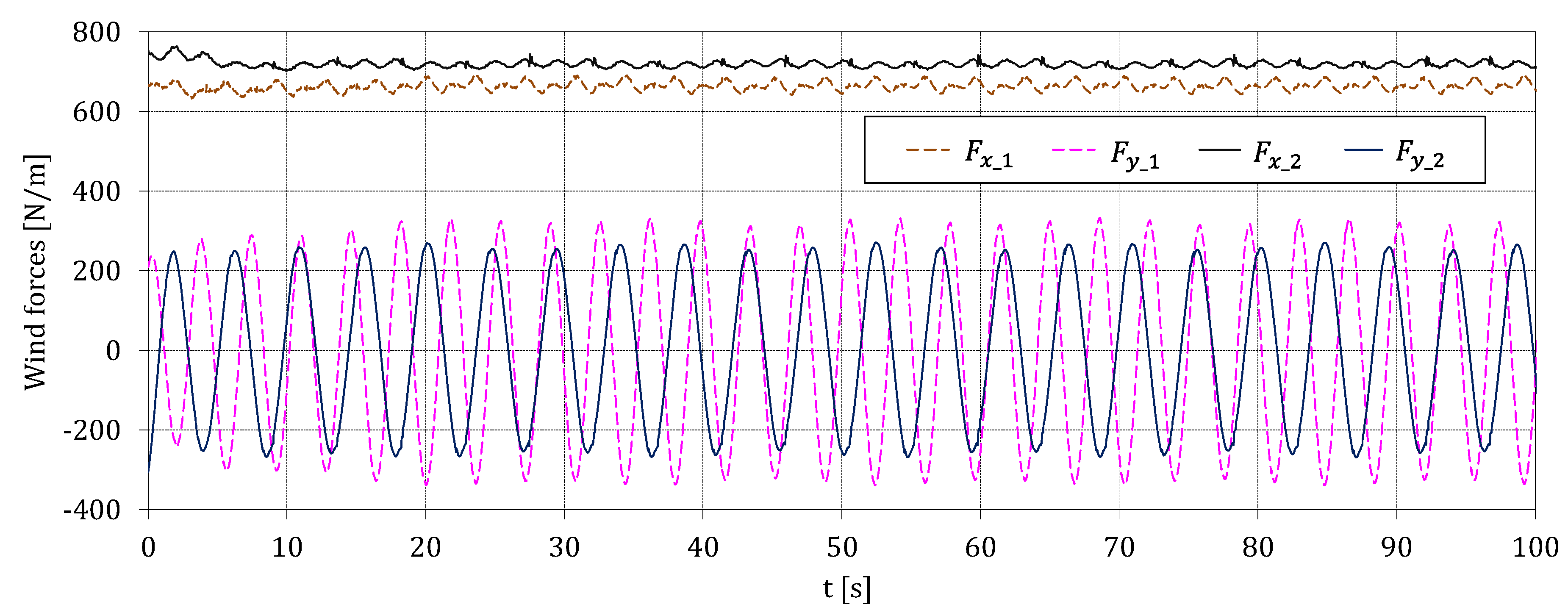
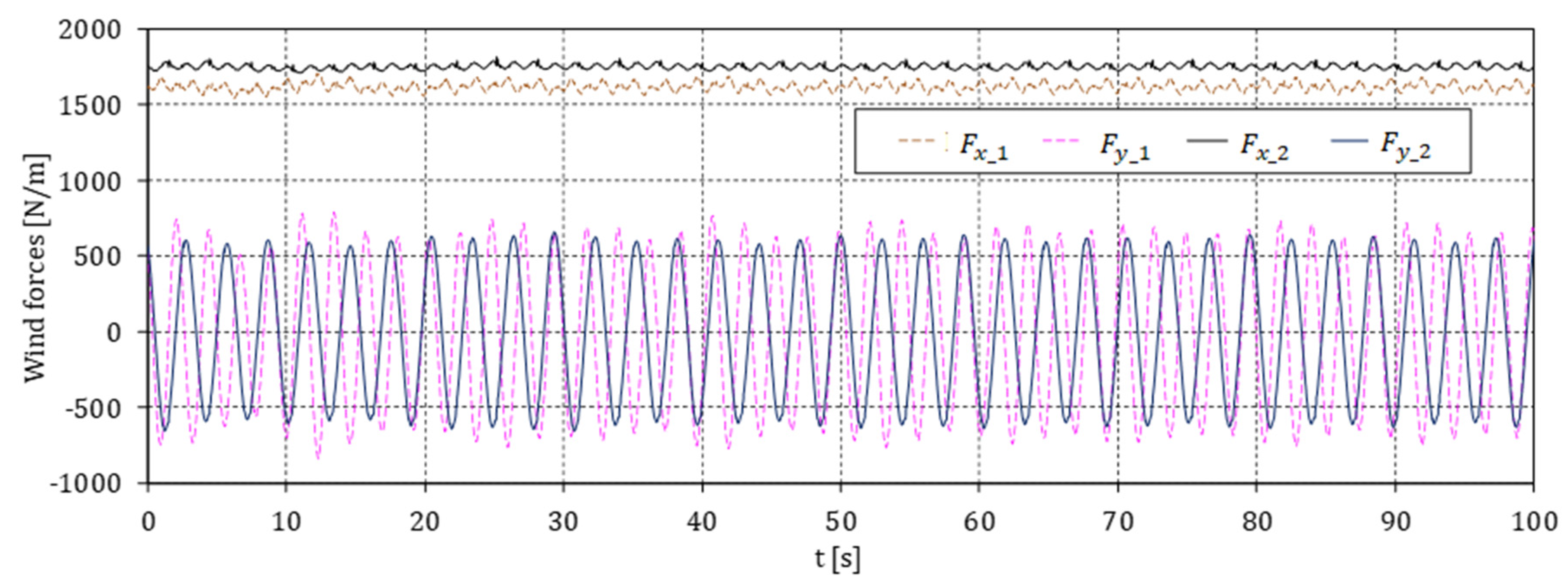
The two scenarios to be discussed in this section are: the old chimney before the installation of TMD and the old chimney equipped with TMD. The time histories of loading for the two planes (_1 and _2) are shown in
Figure 4 and
Figure 5, both in along-wind (
) and across-wind (
) directions.
Table 1 shows the corresponding values for the vortex shedding frequencies in each fluid plane obtained by evaluating the power spectral density of the
and
series, together with the
St number. Note that those frequencies are different for two reasons: the wind speed at these heights is different and diameters are also different.
The computed forces are supposed to act over the chimney as a step-load in the following way: at time
= 0 s the chimney is assumed to be at rest and at that time both
and
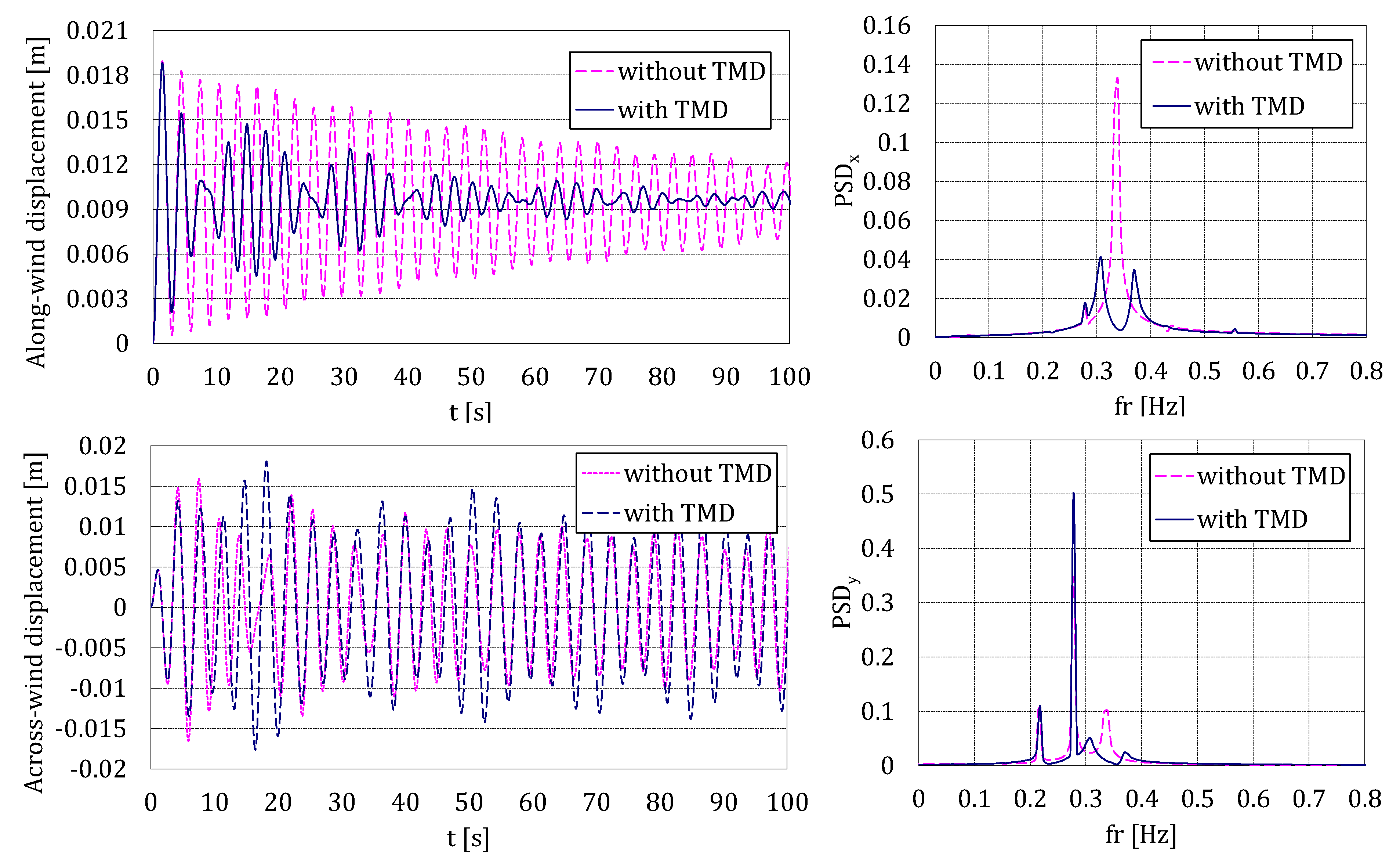
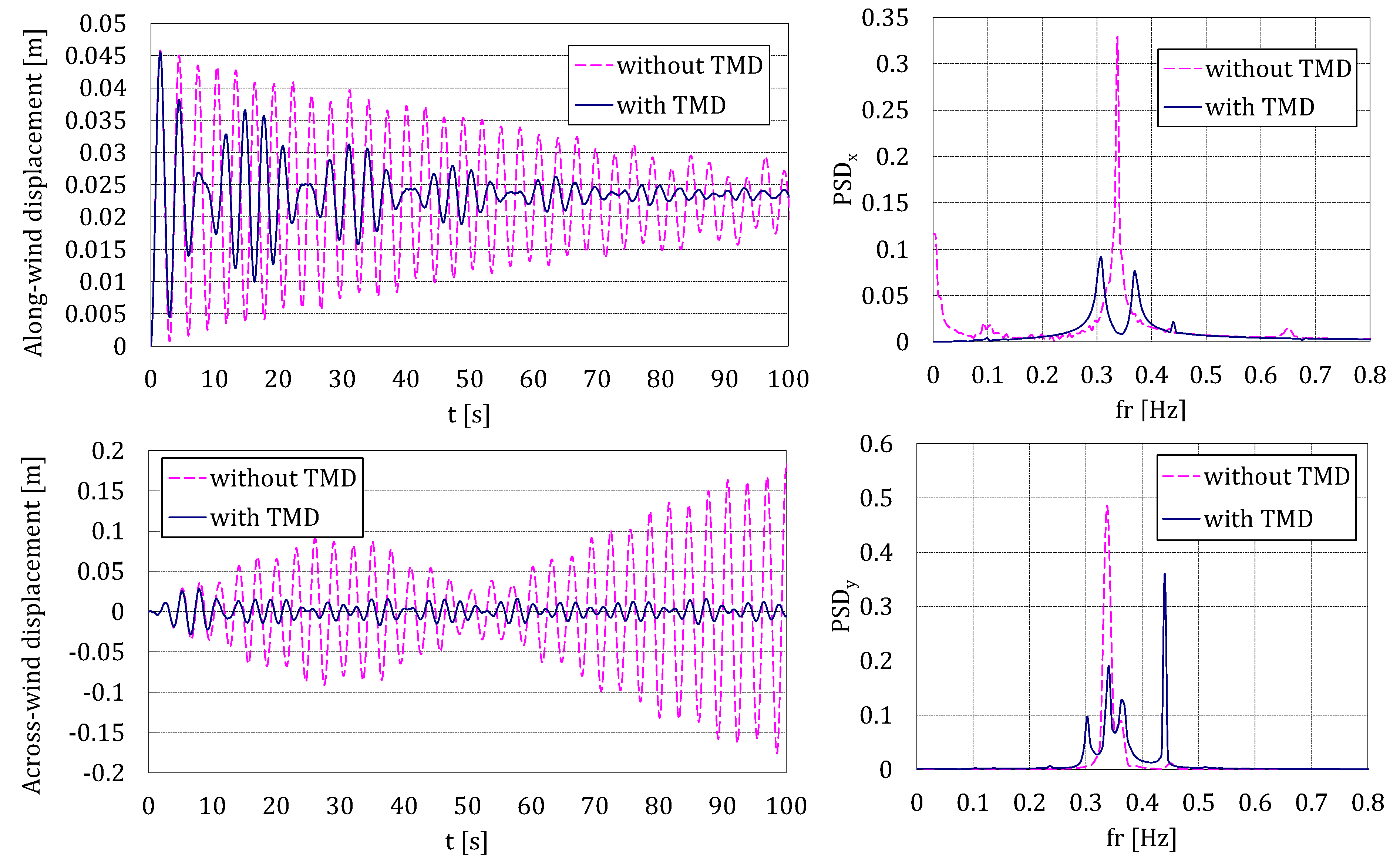
forces are applied suddenly. In this way, it is possible to numerically estimate the damping value using a standard free decay curve-fitting approach. The performance of the TMD and the damping ratios are evaluated using the Stochastic Subspace Identification algorithm from the experimental data. Responses for the two scenarios at
= 167 m (obtained by interpolation between _1 and _2 planes), where the TMD is located, are shown in
Figure 6 and
Figure 7. The corresponding power spectral densities (PSD) are also shown.
In both cases, the TMD is successfully working in the along-wind direction, reducing the transient decay due to the step load. Nevertheless, in the across-wind direction, the performance is very different. For = 7.8 m/s, the low frequencies of the vortex shedding are not enough to make the chimney move at the appropriate frequency (its natural frequency to which the TMD was tuned); while, for = 12.2 m/s, the chimney is excited in a different manner (in amplitude and, mainly, in frequency), in such a way that the TMD is seen to be very efficient, as intended.
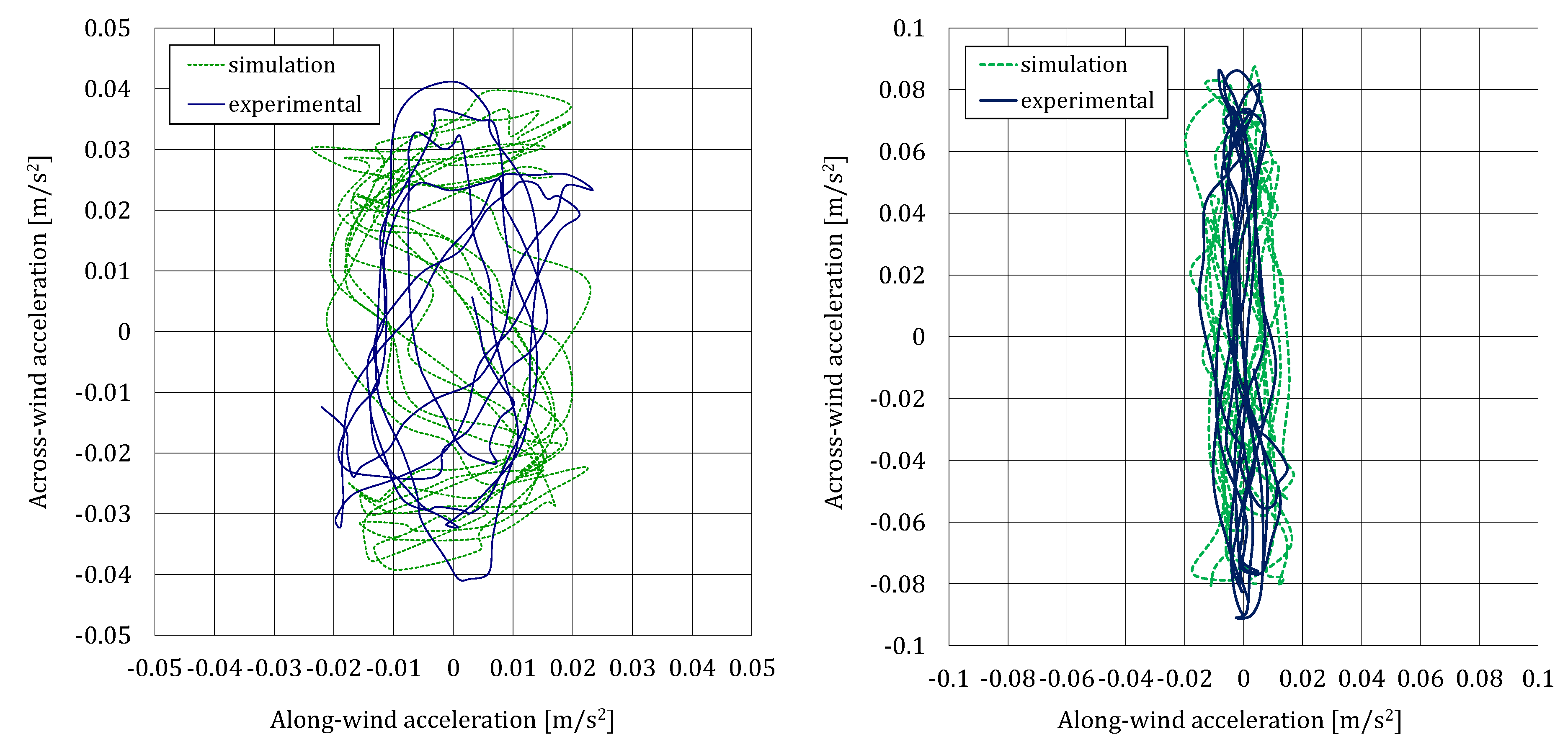
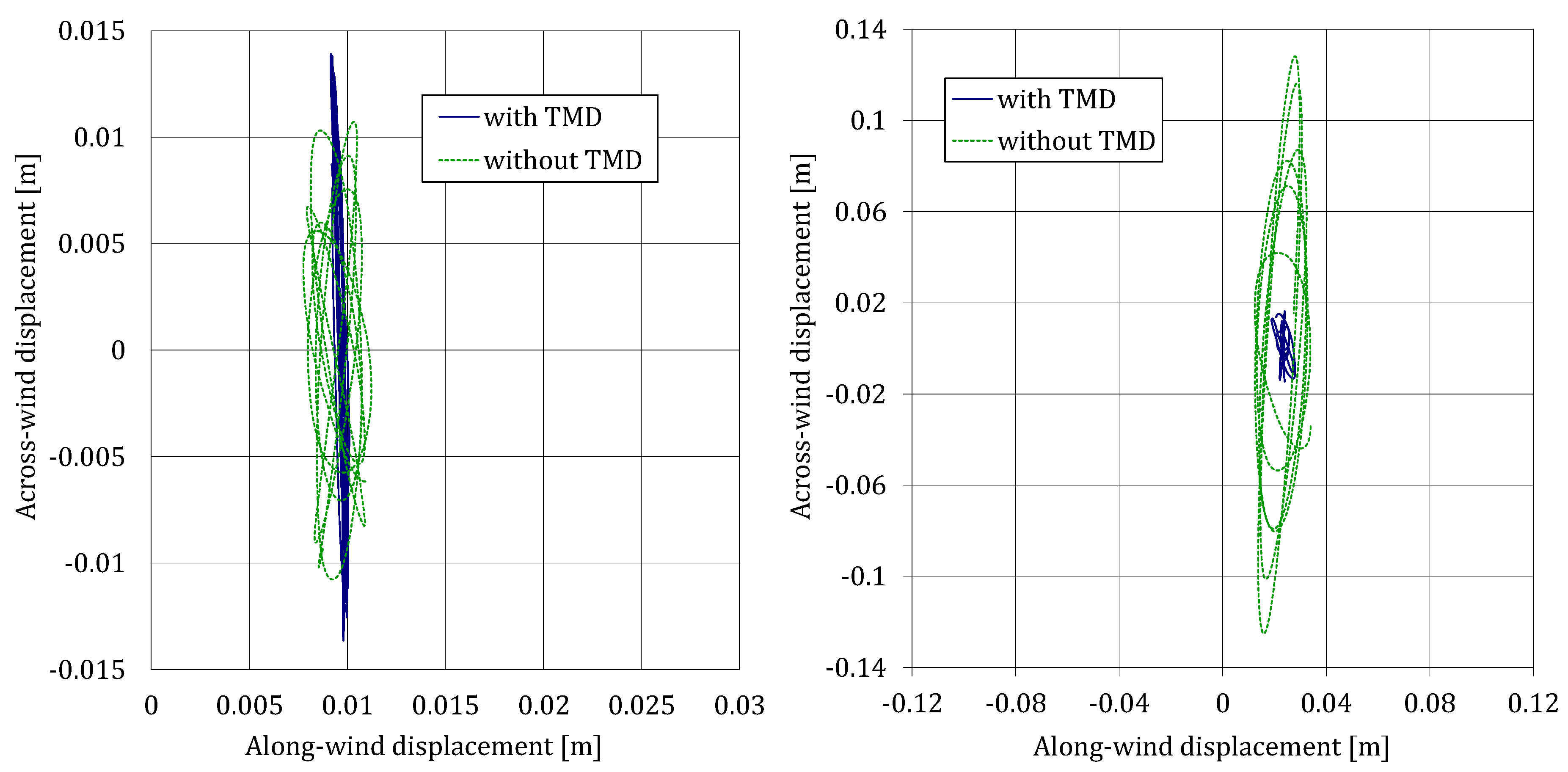
In order to verify that the amplitudes (in
and
directions) of the accelerations are similar, experimental and numerical acceleration orbit plots are compared in
Figure 8. For a clear comparison, only a time interval of 20 s is shown both for
= 7.8 m/s and for
= 12.2 m/s. In addition, computational displacement orbit plots are shown in
Figure 9 for the two scenarios considered. Note that the experimental acceleration data are only available with the TMD attached.
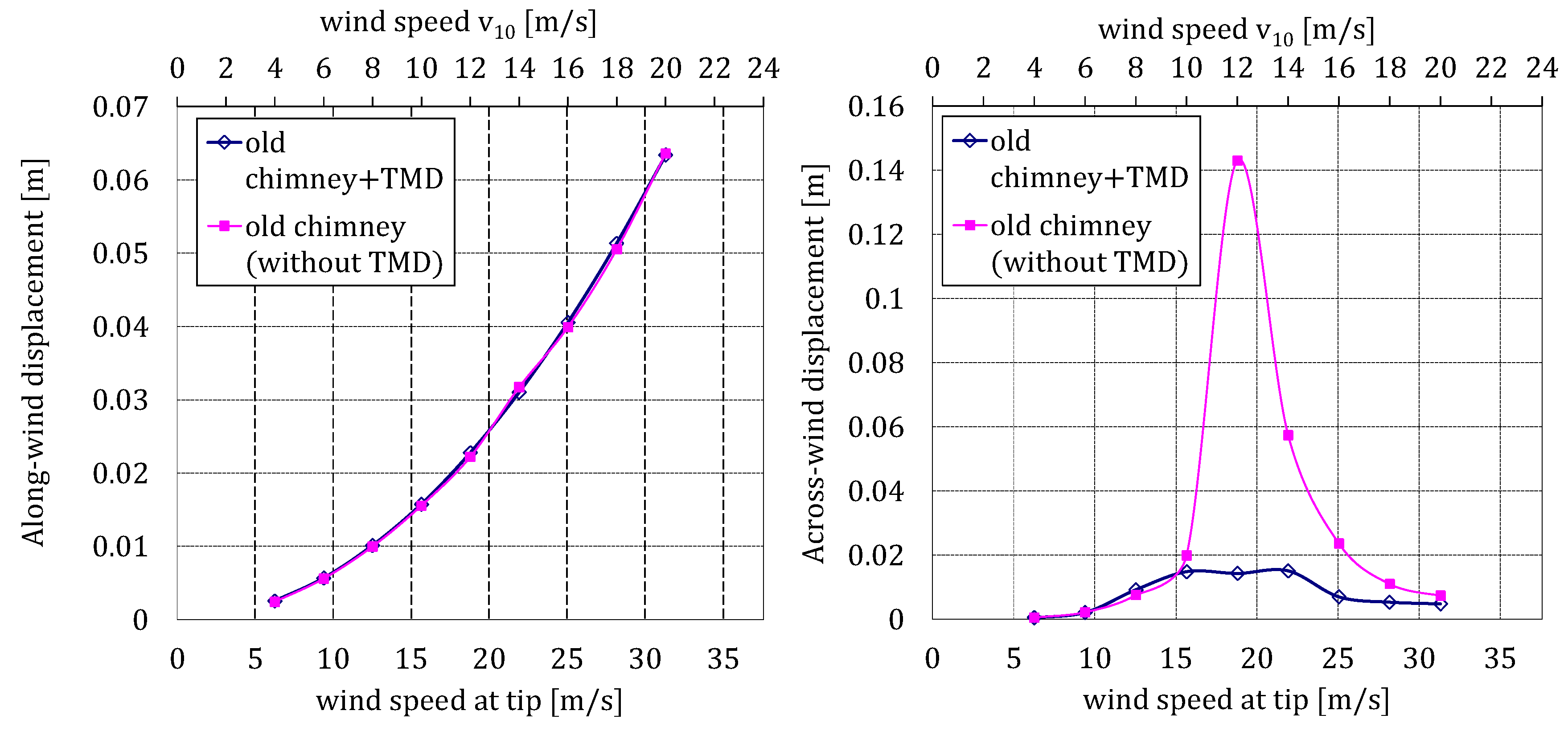
Finally,
Figure 10 shows the along- and across-wind response of the old chimney for the two scenarios and for a range of wind speeds. It is observed that the TMD is very efficient working for the range of wind speeds (
= 10–14 m/s) where the maximum across-wind response of the old chimney occurs.
6. Interference Effects
The distance between the new and old chimneys was a little over 100 m. ACI 307-98 standard [
23] gives no guidance about how to determine the interference effects between chimneys of differing geometries other than “reference to model test of observations or test reports of similar arrangements”. In this work, a numerical study is carried out to determine any additional loading on the old chimney for winds coming from the place where the new chimney is.
In a similar way to the previous section, the new chimney was also modelled with beam finite elements and included in the CFD model. Its first natural frequency was 0.4 Hz and the damping ratio around 1%, according to experimental measurements.
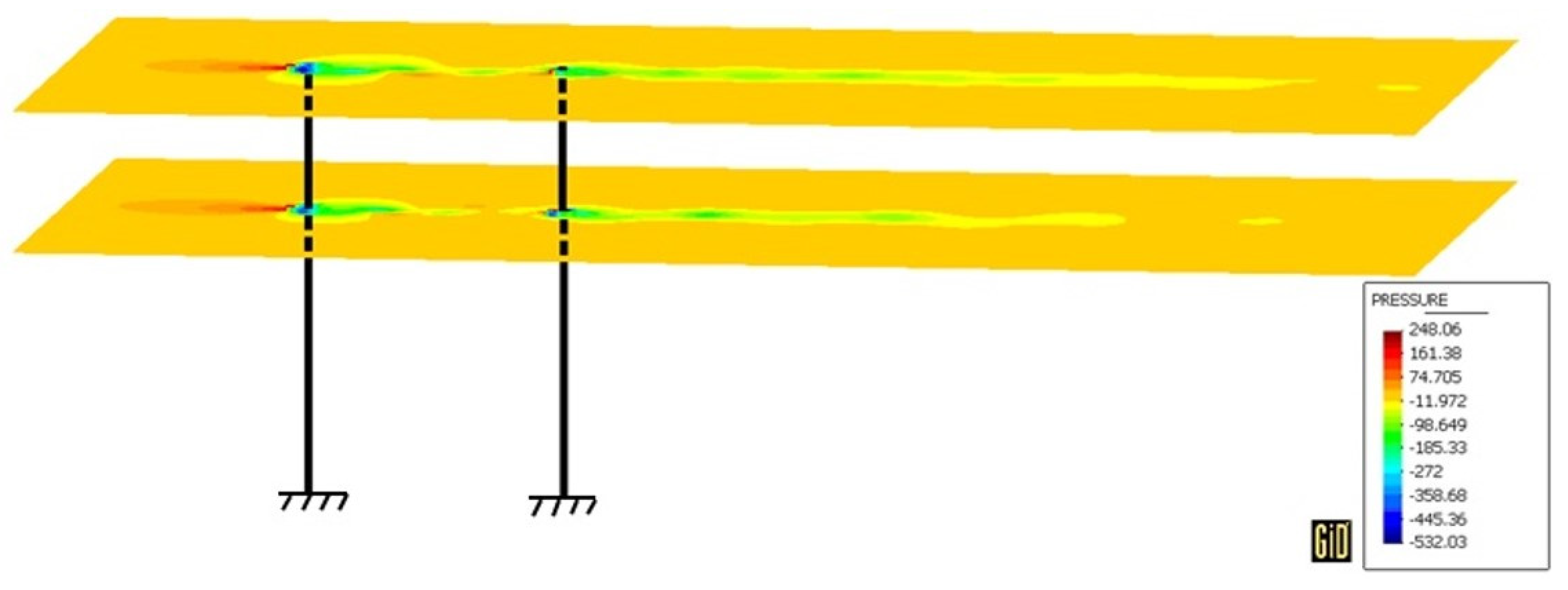
In order to study the interference effects associated with the new chimney, again two scenarios were selected: the old chimney before the installation of TMD and the old chimney equipped with TMD. In both scenarios, the chimneys are supposed to be in-line with the wind direction. The field pressure at a representative instant for
= 12 m/s is shown in
Figure 11.
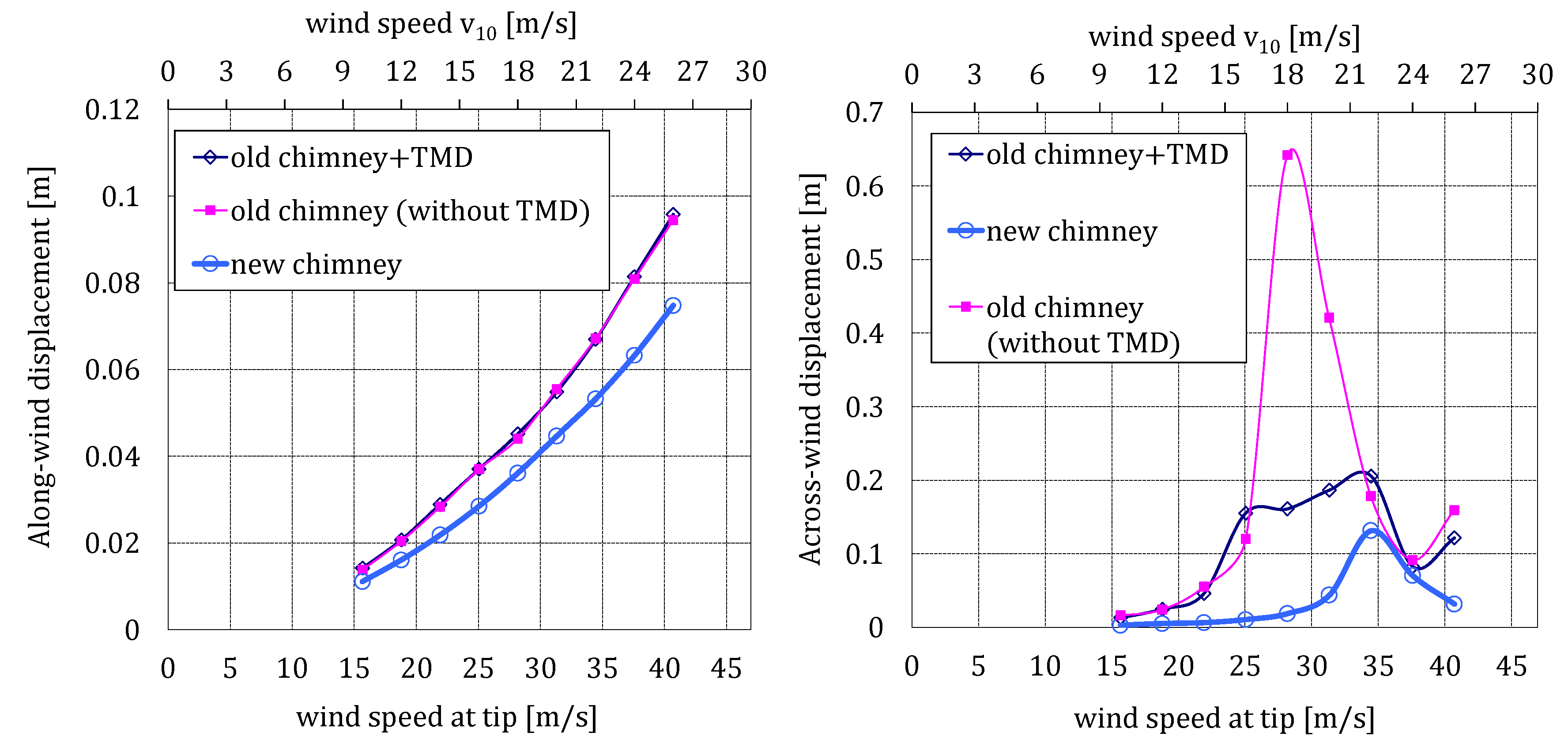
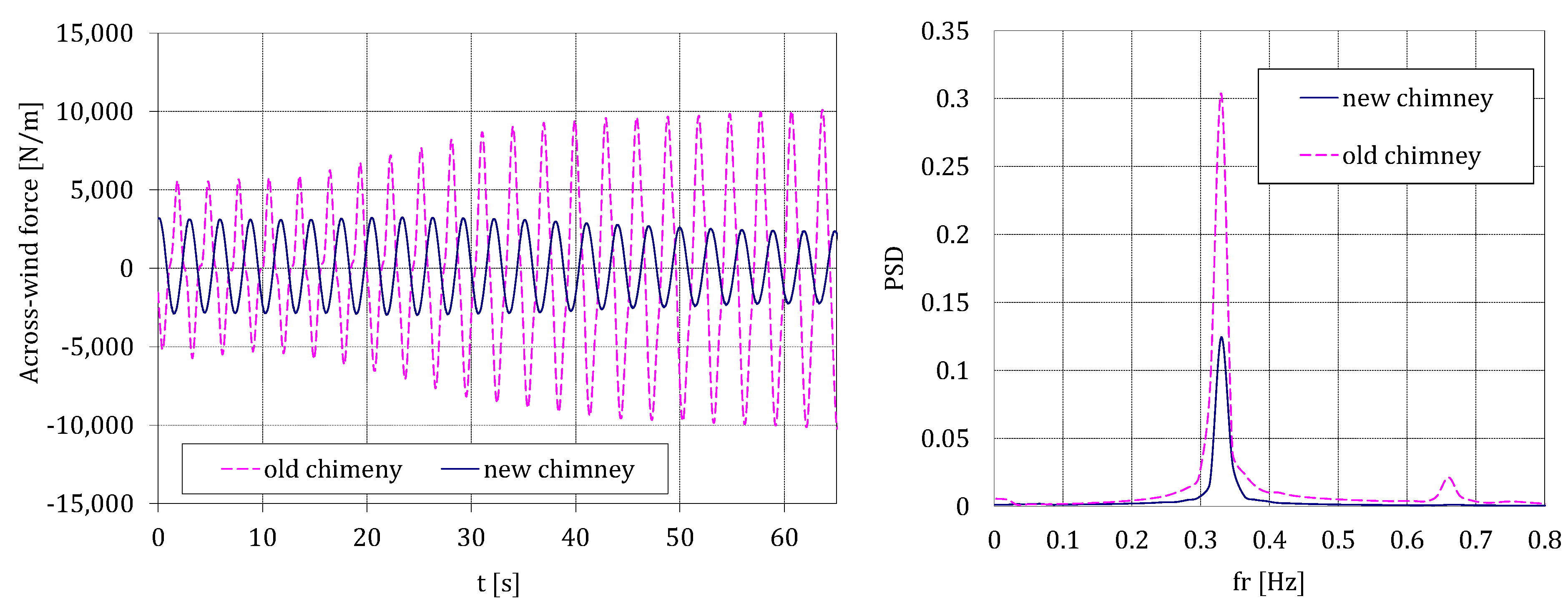
For the two scenarios considered, the along- and across-wind response, at
= 167 m, for the two chimneys, the old one being in-line with the new one, is plotted in
Figure 12. It is observed that the new chimney significantly increases the across-wind loads on the old chimney, as shown in
Figure 13, in which the across-wind time loading and its PSD for the plane located at the tip and
= 18 m/s are plotted. In addition, it is possible to evaluate the effectiveness of the TMD for the range of wind speeds (
= 18–20 m/s) where the largest interference effects occur. It shows a high performance of TMD, decreasing the transverse displacements more than 3 times (as they drop from 0.65 m to 0.2 m, approximately).
It is interesting to compare the very different behaviors in
Figure 10 (only old chimney) and
Figure 12 (in-line chimneys). In the first case, the largest across-wind displacements occur at
= 12 m/s (commanded by the Strouhal law) and in the second case at
= 18 m/s (because of the perturbed wind coming from the new chimney), 50% bigger. Besides,
Figure 12, which is obtained by the proposed FSI-CFD numerical technique, is in accordance with the estimated response of the old chimney, obtained using the Vickery Method [
9]. Note that the wind speed at 183 m when
= 18 m/s is
= 28.16 m/s, being such wind speed not much less than the one estimated in the referred study (31 m/s).
For
= 22 m/s, the estimated transversal displacements with the TMD (around 0.20 m) are even bigger than those for the critical speed,
= 12 m/s (around 0.14 m) for the case with no interference effects (
Figure 9). This reveals the strong influence of the interference phenomenon and the need to account for it from the structural safety point of view.
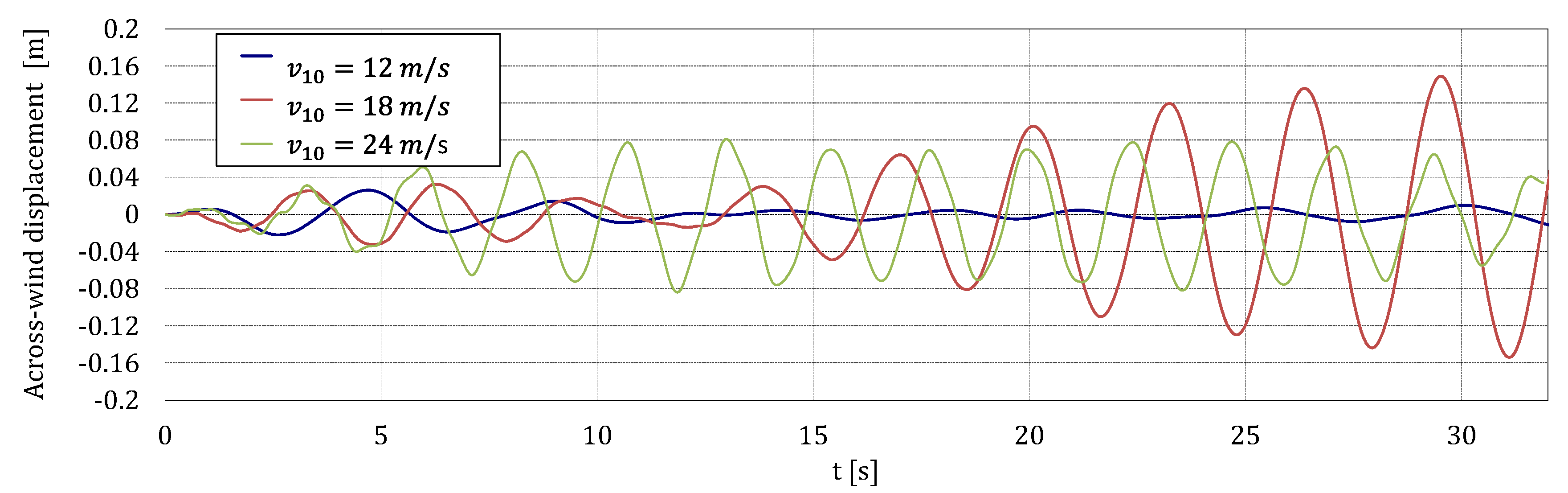
In order to show the performance of the TMD to mitigate the enhanced response due to the interference, time histories of the across-wind displacement of the old chimney at 167 m are plotted in
Figure 14, for different wind speeds
= 12 m/s,
= 18 m/s and
= 24 m/s, respectively.
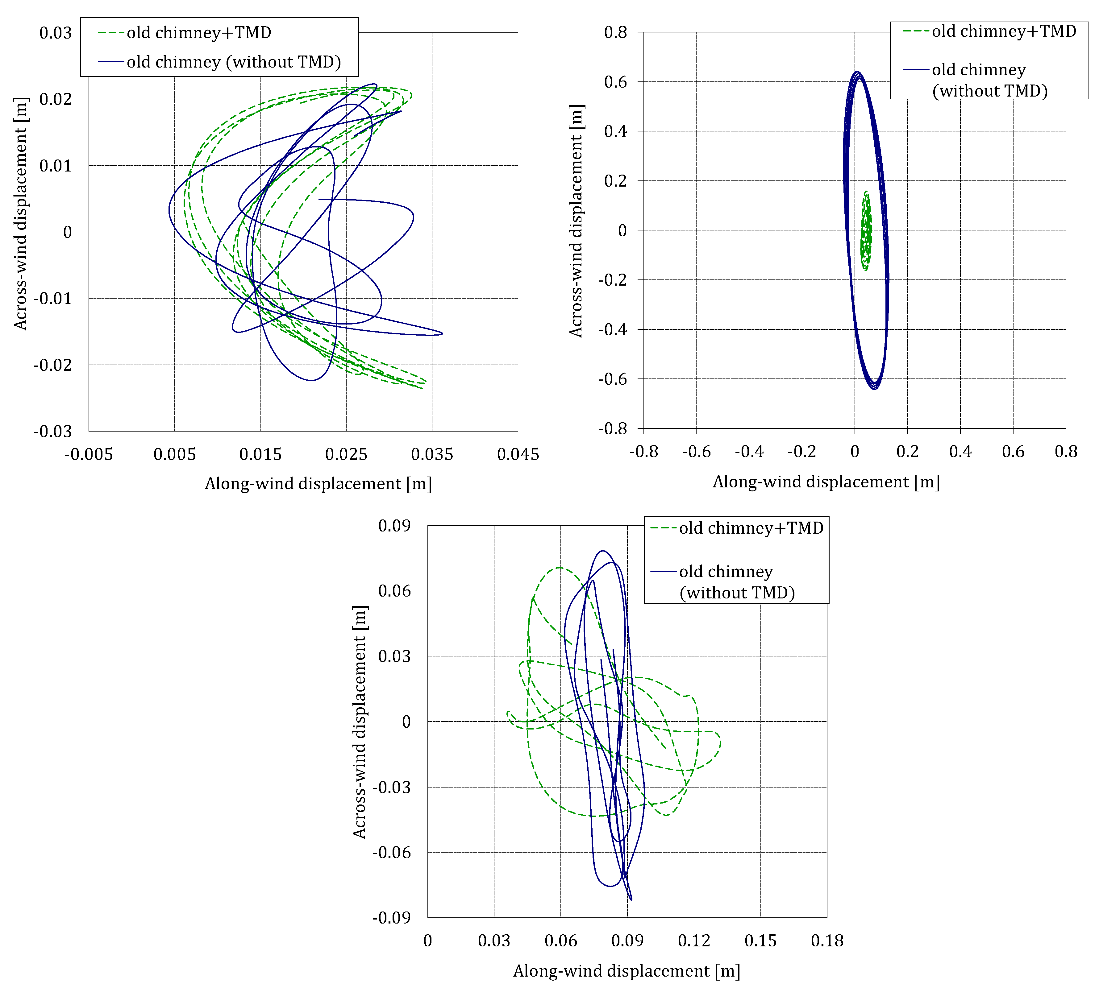
Finally, displacement orbit plots are presented in
Figure 15 for the two scenarios considered and the three selected wind speeds. It is remarkable that without TMD, for
= 18 m/s, the chimney would move up to 0.65 m, around four times the maximum displacement when the TMD is attached.
7. Discussion
The across-wind response of the chimney and the performance of the TMD are very different for each wind speed. For = 18 m/s, the displacements are larger, approximately 0.16 m, due to resonance, and the TMD is successfully mitigating the wind-induced interference effects. However, for = 12 m/s and = 24 m/s, the frequencies of the resultant across-wind forces, 0.23 Hz and 0.45 Hz respectively, are distant from the natural frequency and the chimney is forced to move to a frequency where the TMD is neither efficient nor necessary, with displacements approximately 0.02 m for = 12 m/s and 0.08 m for = 24 m/s, much shorter than for the resonant case, 0.16 m for = 18 m/s).
From the previous graphs, several findings can be obtained. The more noticeable one is that the TMD is only effective when the chimney is oscillating close to its natural frequency, but these movements occur at different wind speeds depending on the interference effects. Without interference effects, the critical wind speed is
= 12 m/s, whereas with interference effects, it is
= 18 m/s. When the excitation frequency is far from the natural frequency, no resonance appears and so the TMD would not be necessary. Outside its design range, the TMD, being inefficient, slightly affects the dynamical behavior of the assembly and the across wind response amplitude might be a little larger with TMD than without it, as shown in
Figure 12 at wind speed around
= 16 m/s and
= 22 m/s.
8. Conclusions
A simplified numerical method for the evaluation of vortex induced vibrations in line-like slender structures has been checked in a particular chimney equipped with a TMD and the interference effects associated with the construction of a new chimney in the vicinity of the previous one. The response of the old chimney is shown to have been very different depending on the wind speed and direction.
From wind directions where no interference effects appear, critical wind speed is around = 12 m/s and the designed TMD is able to reduce estimated transversal displacements from 0.14 m to less than 0.02 m, that is, by over sevenfold. Although this reduction is considerable, this is not the motivation for installing the TMD, but the mitigation of the interference effects.
In addition, the computational results when the old chimney is buffeted by the wake shed of the new one are presented. These results show that the new chimney can significantly amplify the across-wind displacements and loads associated with vortex shedding on the old chimney. In these cases, the effectiveness of the TMD was studied, showing a very efficient performance for the range of wind speeds where the largest interference effects occurred. For winds aligned with the direction of the chimneys, the critical wind speed is not = 12 m/s, but = 18 m/s. The maximum across-wind displacements without TMD are more than 4.5 times bigger (from over 0.14 m to almost 0.65 m) and TMD is able to reduce them from almost 0.65 m to 0.16 m, around four times. But the expected 0.16 m with the TMD are even bigger than the maximum expected displacements without TMD and no interference effects, just over 0.14 m. Although this is the point ( = 18 m/s) of the maximum TMD performance, the maximum expected displacement with TMD appears for = 22 m/s, over 0.20 m, this magnitude being similar to the expected displacement without TMD at that wind speed. Keeping in mind that bending moments and stresses are proportional to the transversal displacement, it is obvious, from the presented values, that interference effects can compromise the structural integrity of the chimney.
This study shows the effectiveness of TMD devices installed in industrial chimneys under wind action and that it is possible to simulate interference effects between them. Finally, the results stress the importance of including interference effects when assessing wind loads for grouped chimneys, for which the current state of knowledge is insufficient and further field data and studies are required.
Author Contributions
Conceptualization, A.V.B. and A.L.; methodology, A.V.B.; validation, A.L. and Á.M.; formal analysis, A.L.; investigation, A.V.B.; resources, A.L.; writing—original draft preparation, A.V.B.; writing—review and editing, A.L. and Á.M.; visualization, A.V.B.; supervision, A.L. and J.M.W.B.; project administration, A.L.; funding acquisition, A.L. and J.M.W.B. All authors have read and agreed to the published version of the manuscript.
Funding
The authors wish to acknowledge to the International Committee on Industrial Chimneys (CICIND) for its technical and financial support.
Institutional Review Board Statement
Not applicable.
Informed Consent Statement
Not applicable.
Data Availability Statement
The data presented in this study are available on request from the corresponding author.
Acknowledgments
The support of Research Project RTI2018-098425 (Spanish Government), together with the predoctoral grant FPU16/01339 from the Ministerio de Educacion (Spanish Government) are acknowledged.
Conflicts of Interest
The authors declare no conflict of interest.
References
- Ruscheweyh, H. Further studies of wind-induced vibrations of grouped stacks. J. Wind Eng. Ind. Aerodyn. 1983, 11, 359–364. [Google Scholar] [CrossRef]
- Niemann, H.J.; Kasperski, M. Interference effects for a group of two reinforced concrete chimneys. J. Fluids Struct. 1999, 13, 987–997. [Google Scholar] [CrossRef]
- Belver, A.V.; Koo, K.; Ibán, A.L. Enhanced Vortex Shedding in a 183 m Industrial Chimney. Adv. Struct. Eng. 2014, 17, 951–960. [Google Scholar] [CrossRef]
- Wang, L.; Fan, X. Failure cases of high chimneys: A review. Eng. Fail. Anal. 2019, 105, 1107–1117. [Google Scholar] [CrossRef]
- Simiu, E.; Scanlan, R.H. Wind’s Effects on Structures: Fundamentals and Applications to Design, 3rd ed.; John Wiley & Sons Inc.: Hoboken, NJ, USA, 1996. [Google Scholar]
- Connor, J.J. Introduction to Structural Motion Control; Prentice Hall Pearson Education: Upper Saddle River, NJ, USA, 2003. [Google Scholar]
- Elias, S.; Matsagar, V.; Datta, T.K. Along-wind response control of chimneys with distributed multiple tuned mass dampers. Struct. Control Health Monit. 2018. [Google Scholar] [CrossRef] [Green Version]
- Griffin, O.M. Vortex shedding from bluff bodies in a shear flow: A review. J. Fluids Eng. 1985, 107, 298–306. [Google Scholar] [CrossRef]
- Vickery, B.J.; Clark, A.W. Lift or across-wind response of tapered stacks. ASCE J. Struct. Div. 1972, 98, 1–20. [Google Scholar]
- Williamson, C.; Govardhan, R. A brief review of recent results in vortex-induced vibrations. J. Wind Eng. Ind. Aerodyn. 2008, 96, 713–735. [Google Scholar] [CrossRef]
- Odijie, A.C.; Ye, J. Effect of Vortex Induced Vibration on a Paired-Column Semisubmersible Platform. Int. J. Struct. Stab. Dyn. 2015, 15, 1540019. [Google Scholar] [CrossRef]
- Belver, A.V.; Ibán, A.L.; Lavín, C.E. Coupling between structural and fluid dynamic problems applied to vortex shedding in a 90 m steel chimney. J. Wind Eng. Ind. Aerodyn. 2012, 100, 30–37. [Google Scholar] [CrossRef]
- Iban, A.L.; Brownjohn, J.M.W.; Belver, A.V.; Lopez-Reyes, P.M.; Koo, K. Numerical modelling for evaluating the TMD performance in an industrial chimney. Wind Struct. 2013, 17, 263–274. [Google Scholar] [CrossRef]
- Krenk, S. Mechanics and Analysis of Beams, Columns and Cables, 2nd ed.; Springer: Berlin/Heidelberg, Germany, 2001. [Google Scholar]
- Dadvand, P.; Rossi, R.; Oñate, E. An object-oriented environment for developing finite element codes for multi-disciplinary applications. Arch. Comput. Methods Eng. 2010, 17, 253–297. [Google Scholar] [CrossRef]
- Pagnini, L.C.; Piccardo, G.; Solari, G. VIV regimes and simplified solutions by the spectral model description. J. Wind Eng. Ind. Aerodyn. 2020, 198. [Google Scholar] [CrossRef]
- Grala, P.; Mércio, A.; Loredo-Souza, A.M.; Rocha, M.M. A method to predict vortex shedding response based on Vickery and Basu model: A proposal for the new Brazilian Wind Code. Eng. Struct. 2019, 198, 109469. [Google Scholar] [CrossRef]
- Arunachalam, S.; Lakshmanan, N. Across-wind response of tall circular chimneys to vortex shedding. J. Wind Eng. Ind. Aerodyn. 2015, 145, 187–195. [Google Scholar] [CrossRef]
- Rossi, R.; Oñate, E. Analysis of some partitioned algorithms for fluid-structure interaction. Eng. Comput. 2010, 27, 20–56. [Google Scholar] [CrossRef]
- Baiges, J.; Codina, R. Variational Multiscale based dissipation models for the estimation of atmospheric seeing. Comput. Fluids 2015, 107, 141–154. [Google Scholar] [CrossRef] [Green Version]
- Maia, N.; Silva, J. Theoretical and Experimental Modal Analysis; Engineering dynamics series; Research Studies Press: Letchworth, UK, 1997. [Google Scholar]
- Flaga, A.; Lipecki, T. Code approaches to vortex shedding and own model. Eng. Struct. 2010, 32, 1530–1536. [Google Scholar] [CrossRef]
- ACI Comittee. Standard Practice for the Design and Construction of Cast-in-Place Reinforced Concrete Chimneys; ACI 307-98; American Concrete Institute: Farmington Hills, MI, USA, 1998. [Google Scholar]
| Publisher’s Note: MDPI stays neutral with regard to jurisdictional claims in published maps and institutional affiliations. |
© 2021 by the authors. Licensee MDPI, Basel, Switzerland. This article is an open access article distributed under the terms and conditions of the Creative Commons Attribution (CC BY) license (http://creativecommons.org/licenses/by/4.0/).

 ,
, 


