Development of a Novel Miniaturized Electromagnetic Actuator for a Modular Serial Manipulator


1
Department of Mechanical Engineering, Benha Faculty of Engineering, Benha University, Benha 13511, Egypt
2
Department of Mechanical Engineering, Hanbat National University, Daejeon 34158, Korea
*
Author to whom correspondence should be addressed.
Actuators 2021, 10(1), 14; https://0-doi-org.brum.beds.ac.uk/10.3390/act10010014
Submission received: 8 December 2020
/
Revised: 9 January 2021
/
Accepted: 11 January 2021
/
Published: 14 January 2021
(This article belongs to the Section Actuators for Robotics)
Abstract
:This paper presents a novel miniaturized and modular dual-axis Electromagnetic Actuator (EMA). It mainly consists of two electromagnetic coils in an orthogonal orientation with a permanent magnet fixed on a free moving frame that rotates around two axes/joints. By actuating either of the coils, the free moving frame rotates around the corresponding axis. Simulations and experimental analyses are conducted in order to characterize the performance of our EMA. Thus, our actuator achieves a torque of 100 mNm at simulation and 80 mNm through experimentation for the same applied current. Additionally, it can achieve a rotation of (≈0.2 rad), according to simulations and experimental work. Because of modularity, multiple units of our EMA can be connected together in different configuration to serve in several applications. As an example application, we used a pair of our EMA in order to generate a miniaturized 4-DOF robotic manipulator. This manipulator demonstrates the advantages of light weight, small size, and a high level of manipulability. Kinematic analyses and experimental work are performed in order to validate our manipulator and to prove the concept of our proposed EMA. Through this experiment, we applied an open-loop controller on our EMAs, so that the end-effector of our manipulator can track a predefined circular trajectory. The movement of the end-effector is detected while using image processing techniques. Although we used an open-loop controller, our manipulator is still able to track the trajectory with moderate errors.
1. Introduction
For long decades, Electromagnetic Actuators (EMAs) have perfectly served in several engineering applications with proven accuracy and reliability. They have never stopped progressing since the reveal of conventional motors that undoubtedly revolutionized the actuation technology. Since then, actuators that exploit electromagnetic principles (i.e., motors, solenoids, and relays) are found in widespread applications and devices that we use in our daily life.
In addition to the commonly used techniques of EMAs, several research works have been recently conducted in order to develop innovative actuators that can be employed to solve engineering problems of certain complexity. For example, they have been used in microrobotics applications in environments with limited dimensions [1,2,3,4,5]. Additionally, they have been also exploited in drug delivery and therapeutic applications to guide Magnetic Nanoparticles (MNP) in blood vessels [6,7,8]. Basically, microrobots can be used in order to perform tasks, like diagnosis, inspection, drug delivery, and minimally invasive surgeries. The electromagnetic actuation system has been utilized to actuate a microrobot that achieved a flexible motion inside narrow pipes for diagnosis purposes [1]. Another novel EMA has been developed in order to provide two-dimensional [2] and three-dimensional [3] locomotion of a microrobot for intravascular therapy. The microrobot actuated by this EMA was able to follow a predefined track and move at any direction in the three-dimensional (3D) space. Additional research work has been conducted in order to develop equitranslation and axial rotation in the same microrobot [4]. The developed microrobot has been validated in an artificial blood vessel and it could move to the targeted position. A gradient-enhanced electromagnetic actuation system has been also developed to precisely drive microrobots [5].
EMAs have not only been used to develop robots in micro scale, but also they have been used to develop robots with larger size and different purposes [9,10,11,12]. The electromagnetic linear actuator has been used to develop a bristle-based inchworm mobile robot [9]. Large scaled and actual sized prototypes have been built to validate the performance. Another EMA with compliance advantage has been developed for soft robotic and biological-inspired applications [10]. A prototype of this bio-inspired soft actuator has been developed and tested for grasping motion. Another novel EMA has been proposed to create an insect-inspired flapping-wing robot [11]. This miniaturized robot with 80 mg weight and 3.5 cm wingspan could produce a sufficient thrust force to liftoff. Additional bio-inspired robot has been developed while using EMA to mimic the jellyfish swimming motion [12]. This robot that has 17 mm length and 0.5 mm thickness could properly perform 3D swimming motions.
The main contribution of this paper is to present a novel miniaturized and modular dual-axis electromagnetic actuator for several applications. The modularity of our actuator gives an extra privilege to connect several modules together, providing more potential applications. They can be used in order to generate a snake-like robot if we connected multiple modules in series. They can also be used to generate a quadruped robot if connected in a parallel configuration. However, in this paper, we present a spatial multi-DOF robotic manipulator while using a pair of our dual-axis electromagnetic actuators. The robot that is presented in this research shows high level of manipulability, light weight, and small size. The orientation and position of the end-effector can be changed within the workspace by applying electric current to the electromagnetic actuators at each joint. Forward and inverse kinematics of the robot are studied in order to provide trajectory planning for any predefined end-effector pose (position and orientation).
The paper is organized, as follows: the next section describes our proposed dual-axis EMA design, working principle, and performance. Section 3 shows a robotic manipulator that was created using our novel actuator with the corresponding forward and inverse kinematic analyses. The experimental setup and open-loop control system are described in Section 4. Finally, the conclusions are discussed in Section 5.
2. Dual-Axis Electromagnetic Actuator
2.1. Actuator Design
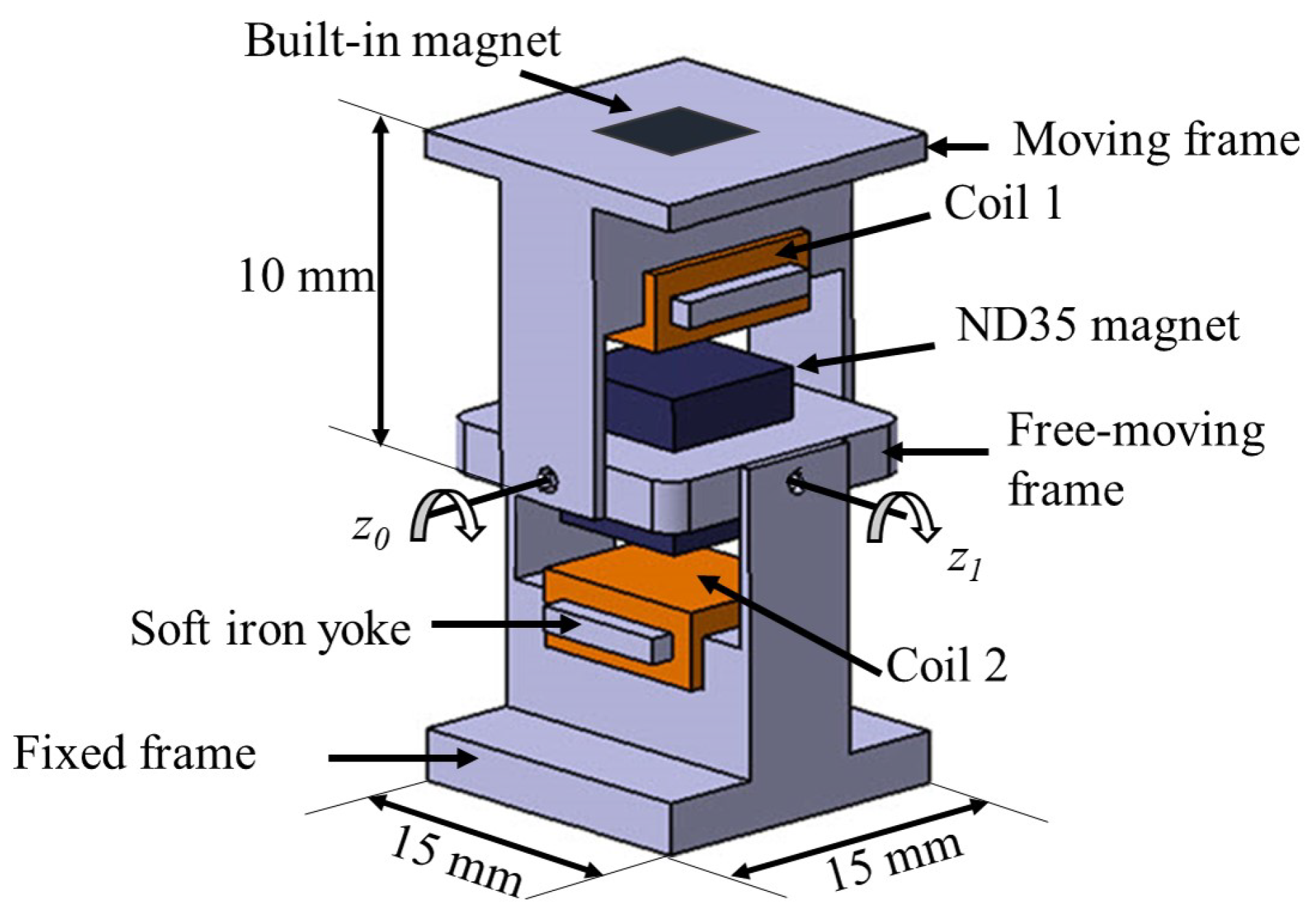
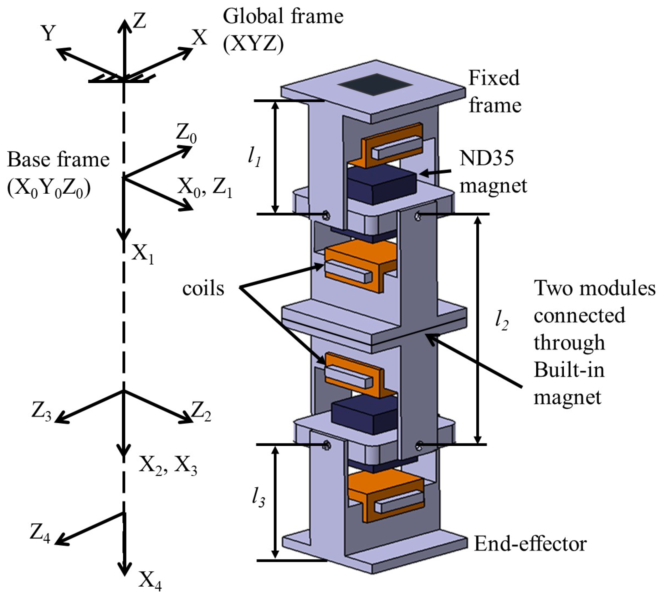
Figure 1 shows the schematic drawing of our dual-axis electromagnetic actuators. Basically, our EMA consists of two perpendicular frames (a fixed frame and a moving frame) that are connected together through another free-moving frame. This free-moving frame is suspended on two axes that allow for rotation around x and y axes. Electromagnetic coils are attached to both the fixed and the moving frames. Each coil has around 820 turns with a resistance of 58 . A soft iron yoke is attached inside the coils in order to concentrate and maintain the generated magnetic field by the coils. A permanent magnet of 5 mm is fixed in the free-moving frame as a moving target that will move according to the energized coil. Another built-in magnet is used at the two ends of each module to allow for connection with further modules. Additionally, this built-in magnet is fixed in an opposite orientation to the magnet of the free-moving frame to concentrate and maintain the magnetic field in the vertical direction, as shown in Figure 2. In this research, rare-earth magnet (Neodymium ND35) is used, because it is the strongest type of commercially available permanent magnets.
2.2. Working Principle of the Electromagnetic Actuator
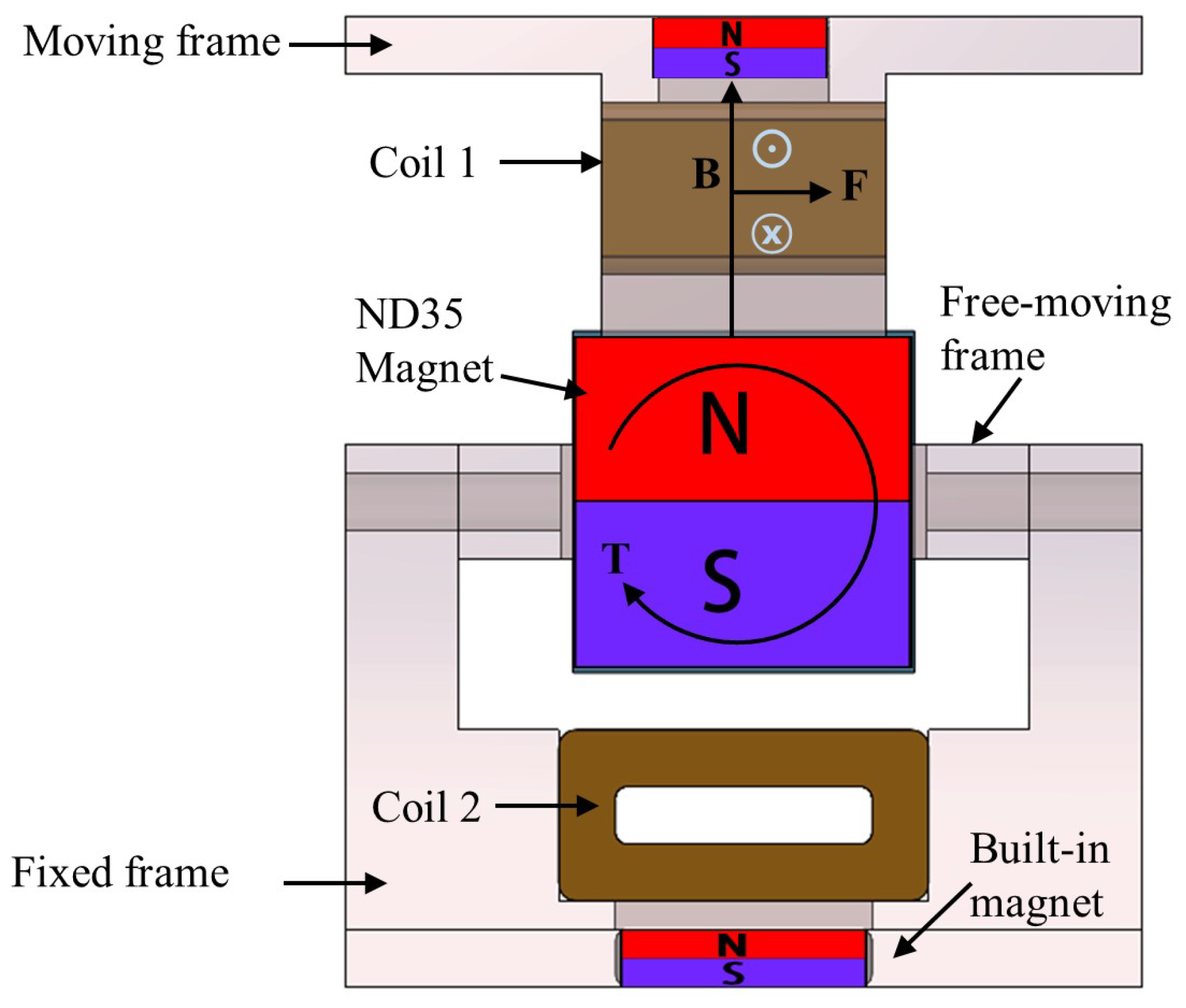
The actuation principle of our EMA mainly depends on generating Lorentz force (F) while using current-carrying coils and permanent magnets. Figure 2 demonstrates the direction of the generated Lorentz force (F) that can be determined by the left-hand rule for a current-carrying wire in a magnetic field. The direction of this force can be changed by changing the direction of the current supplied to the coils. Accordingly, by energizing coil 1, the moving frame experiences a torque (T) and rotates around the axis . Similarly, the free-moving frame can rotate around axis , according to the direction of the current supplied to coil 2.
The dynamic equations of the electromagnetic actuator are modelled similar to that of DC motor, as mentioned in [13]. Thus, the dynamic equations of the actuator can be written as:
where J is the mass moment of inertia of the actuator; , and are the angular acceleration, angular velocity, and rotation angle, respectively; is the restoring torque that rotates the permanent magnet to the default position; is the torque that rotates the permanent magnet to a certain angle that is based on the magnetic field generated at the coils; and are the restoring torque constant and the electric torque constant, respectively; I is the electric current that is applied to the coils; V is the applied voltage; R is the resistance of the coil, while is the back electromotive force (back-EMF) constant. Thus, the relation between the rotation angle and applied voltage can be obtained, as follows,
Our EMA is modelled similarly to linear DC motor (i.e., voice coil motor). The main characteristic of DC motor is that the output torque is directly proportional to the applied current, as shown in Equation (3). The ratio between the torque and current is the fixed value of the torque constant (motor constant). The difference of our EMA is restoring constant, as shown in Equation (2). We assume that the magnetic torque without current is proportional to the rotational angle for simple mathematical modeling. Thus, linear behavior is observed in the characteristics of our EMA in simulations and experiments.
2.3. Characterization Analyses of Our Electromagnetic Actuator
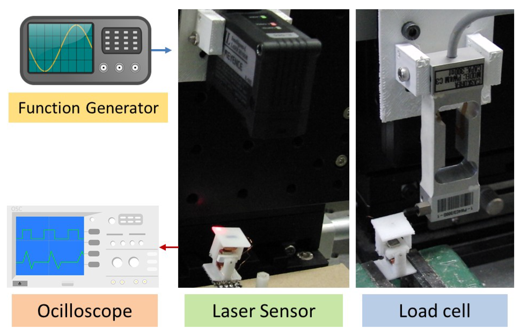
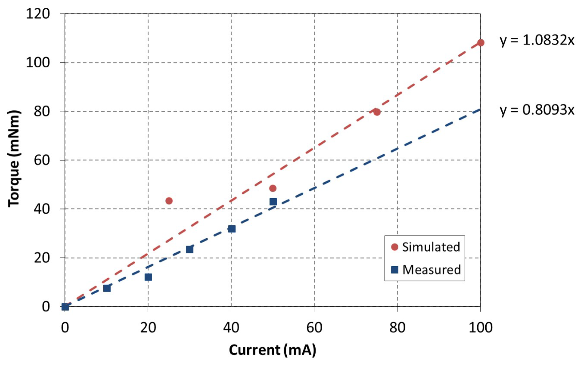
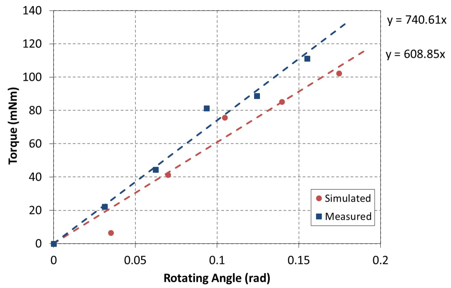
Finite Element (FE) simulation and experimental analyses have been conducted in order to validate the performance of our developed actuator. Figure 3 depicts the simulation results that were obtained by FE Analyses. In this simulation, we have increased the electric current gradually from 0 to 100 mA and the corresponding torque and angle of rotation have been recorded accordingly. Whereas, Figure 4 shows the experimental setup that is used for the characterization of our EMA. In this experiment, we have used a load cell and a laser sensor to measure the torque and the angle of rotation. Additionally, we have used a function generator to supply the electric current that is required to activate the coils. Thereafter, we have plotted the results that were obtained from both the simulation and experimental analyses in same figures, as shown in Figure 5 and Figure 6. The simulation shows that the actuator can reach up to 100 mNm, whereas it could only achieve 80 mNm through experimentation for the same applied current. Hence, by applying 100 mA at each coil with 58 , the maximum power that is consumed at each coil is 0.58 watt. Additionally, simulations and experimental work show that the angle of rotation of the actuator can reach up to (≈0.2 rad). The difference between simulation and experimental results is due to mechanical errors, different material properties, and simulation parameters. However, the obtained results show that our EMA achieves a linear behavior.
3. Manipulator Design and Kinematic Analyses
3.1. Manipulator Design
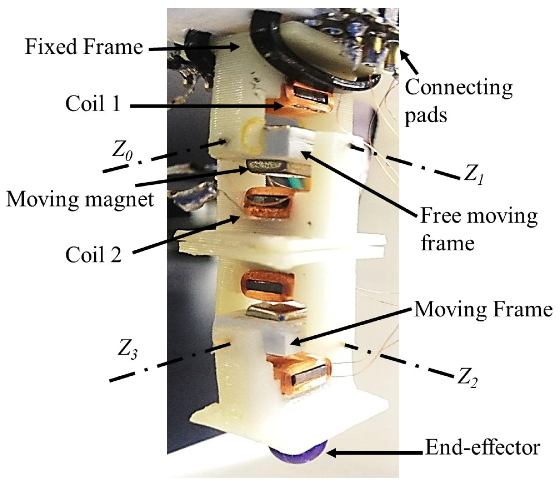
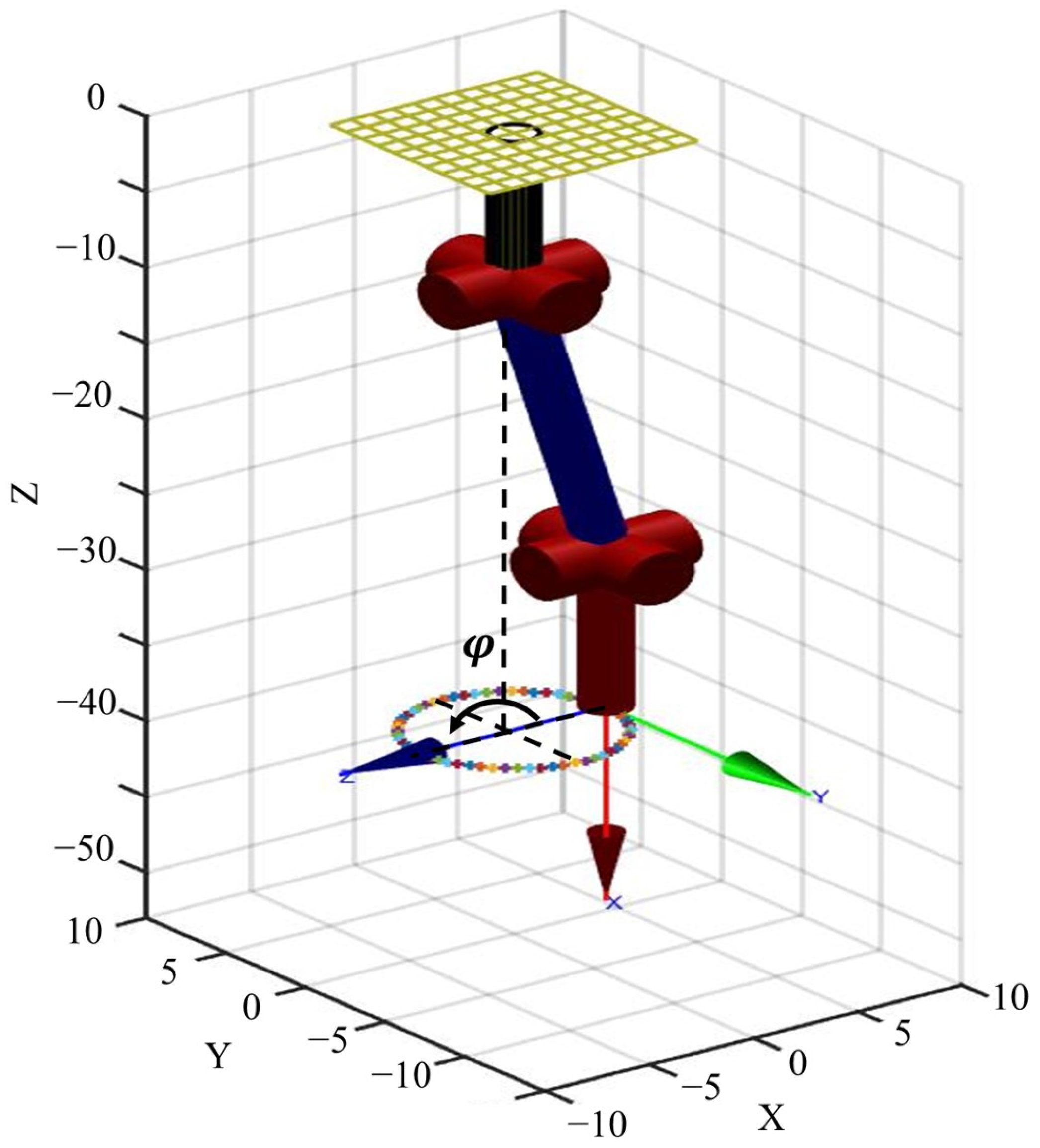
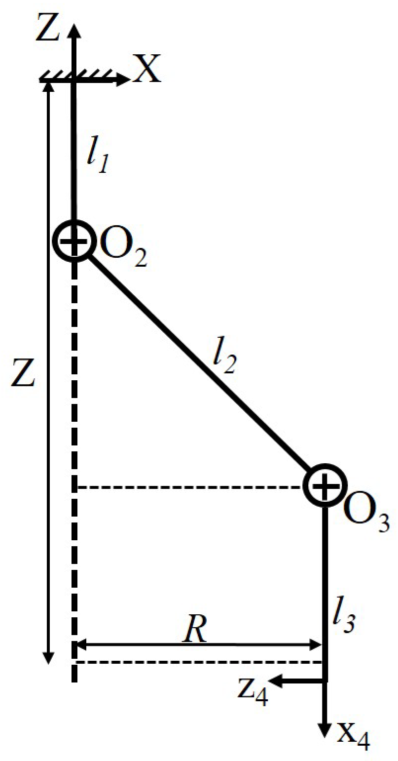
Multiple modules of our proposed electromagnetic actuator can be connected together in order to generate multi-DOF manipulator. However, in this research, we implement a 4-DOF manipulator that consists of a pair of dual-axis electromagnetic modules of actuators. Figure 7 depicts the 4-DOF robot that formed by connecting two modules of electromagnetic actuators together through the built-in magnet. Our robot is a ceiling-mounted robot, such that the fixed frame of our EMA is flipped to the upside. The assembled manipulator has a small size of 15 × 15 × 40 mm, while the total mass is only 6 g for both of the two modules. The length of our robot links are mm, mm, and mm. The manipulator is designed to be modular, thus the rank of the manipulators DOF can be increased to multiples of 2, which is the number of joints available at each module. However, the maximum number of modules connected in series is limited by the maximum torque that is generated by our EMA. Given that the maximum torque generated by our EMA is 100 mNm, then our actuator is able to hold around (3 modules × 3 grams) applied perpendicularly to a one-meter-long moment arm. Figure 8 shows a prototype of the real 4-DOF manipulator. The links are made of Acrylonitrile Butadiene Styrene (ABS) material and created by 3D printing technology. Electromagnetic coils are installed and glued in a tight housing. The terminals of the coils are soldered to connecting pads at the fixed frame on top of the robot. Thus, the control signal used to actuate the coils will be provided through these connecting pads. By applying the proper control signal at each coil, the pose of the manipulator’s end-effector will be ultimately changed.
3.2. Forward Kinematics
The forward kinematics is used to find the position and orientation of the end-effector given the values of the joint angles of the robot [14]. According to Denavet–Hartenberg (D-H) convention, the coordinate frames are attached to the joints of our 4-DOF robot, as shown in Figure 7. Standard D-H parameters, including the joint angle (), link offset (d), link length (a), and link twist angle () are determined for our 4-DOF robot, as shown in Table 1. Note that, in the configuration of our 4-DOF robot, we consider an offset of in the positive direction of . The homogeneous transformation matrices of each joint can be calculated from Equation (6), where , , , and are the joint angle, link twist angle, link offset, and link length at the joint, respectively. Additionally, S and C are the trigonometric functions Sine and Cosine, respectively.
The total transformation matrix () that represents the position and orientation of the end-effector with respect to the base can be obtained by the multiplication of the successive transformation matrices at each joint, as per Equation (7).
Because our 4-DOF robot is a ceiling-mounted robot (i.e., directed downwards), the coordinate frame of robot base should be transformed from the default frame O- to a different orientation of -, as shown in Figure 7. The base transformation matrix () can be obtained by substitution in Equation (6) for , , and . Hence, can be found as
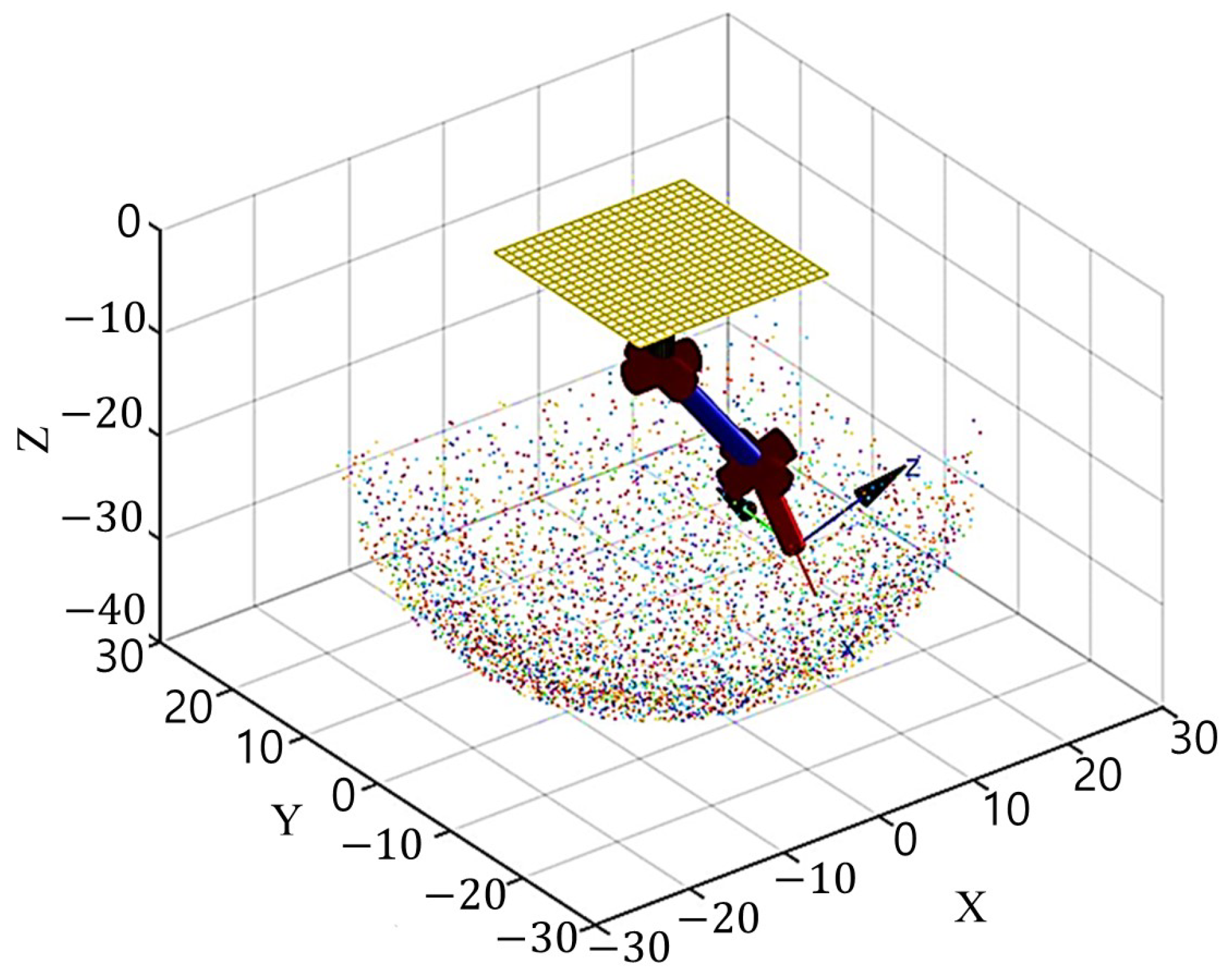
Figure 9 depicts the boundaries of the workspace of the robot while having joint angles limited to ().
3.3. Inverse Kinematics
Solving the inverse kinematics problem is usually important in robotics applications, because it is used to determine the joint variables that are required to achieve a predefined end-effector pose (position and orientation). Typically, manipulators should follow a set of predefined points with a prescribed orientation to perform a definite task while also avoiding potential obstacles. This problem is usually more complex than the forward kinematics problem, because it involves the solution of a nonlinear equations in multiple variables. In this research, a closed-form solution of the inverse kinematics problem is analytically obtained while using the algebraic method [15]. Using this general form solution, our manipulator can achieve any required pose within the reachable workspace. This solution is obtained by solving Equation (9), which is obtained by manipulating Equation (7).
where is the transformation matrix of the joint i and is the transformation matrix of the desired pose of the end-effector and it is defined as,
where X, Y, and Z are the position of the end-effector and represents the elements of the orientation matrix of the end-effector. Hence, a closed-form inverse kinematics solution that describes the joint angles that are required to achieve any predefined pose could be obtained, as follows,
The radius (R) of this predefined track can be found through the structure geometry that is shown in Figure 11 by the relation,
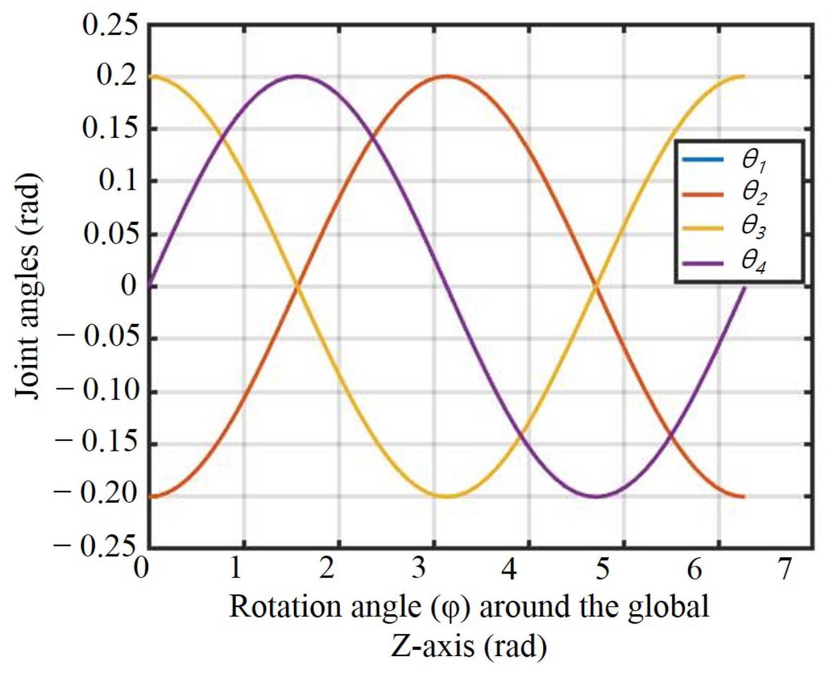
From this equation, the radius (R) is directly related to the position of the end-effector in the Z direction. Hence, the end-effector of our robot could achieve a circle of mm radius in the XY plane at a distance of mm in the Z direction. The joints’ angles that are required to achieve this circular trajectory are presented in Figure 12. In this figure, the curves of and are identical, whereas the curve of is the mirror of the curve of according to the inverse kinematics solution for the predefined circular track.
4. Experimental Setup and Open-Loop Control System
4.1. System Setup
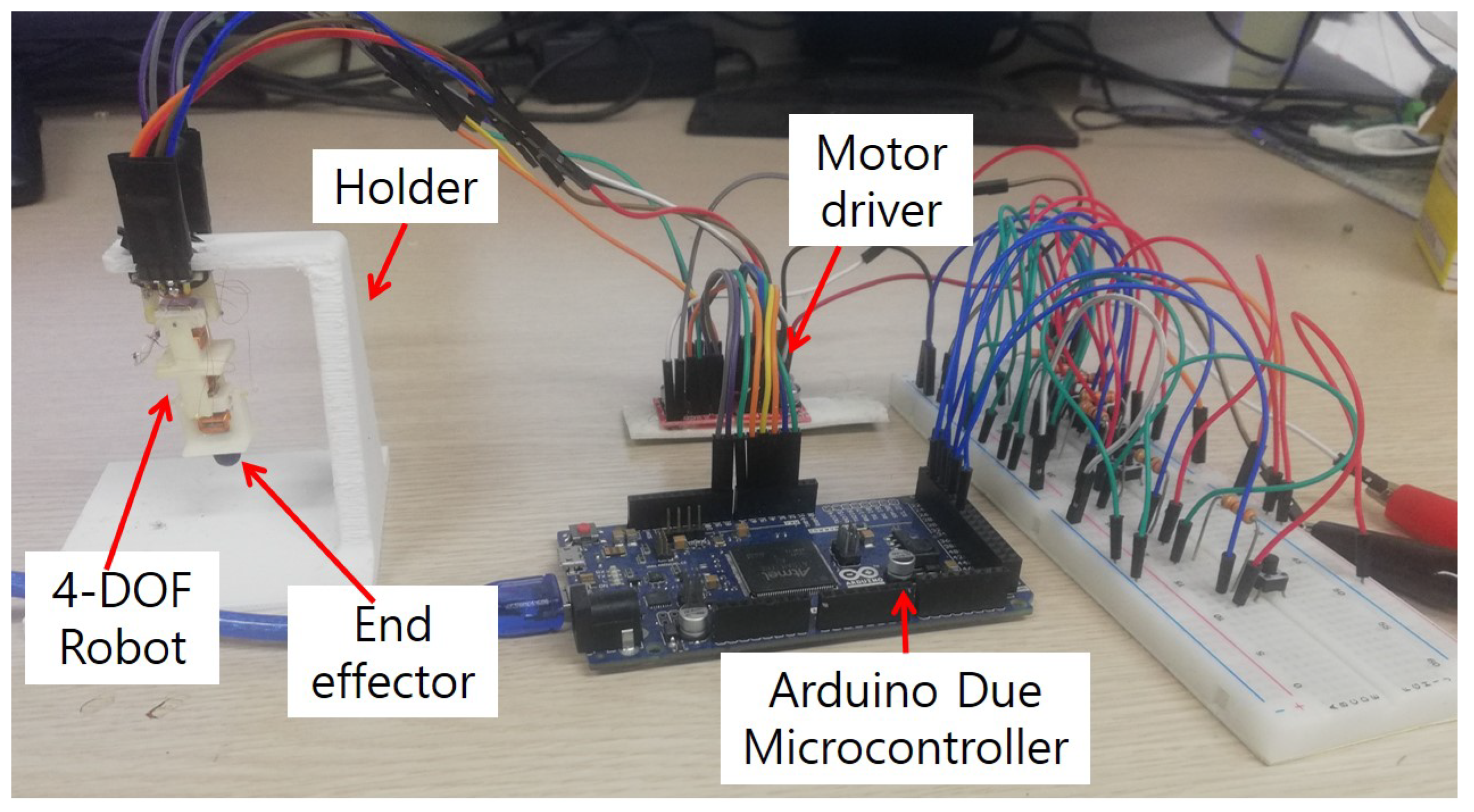
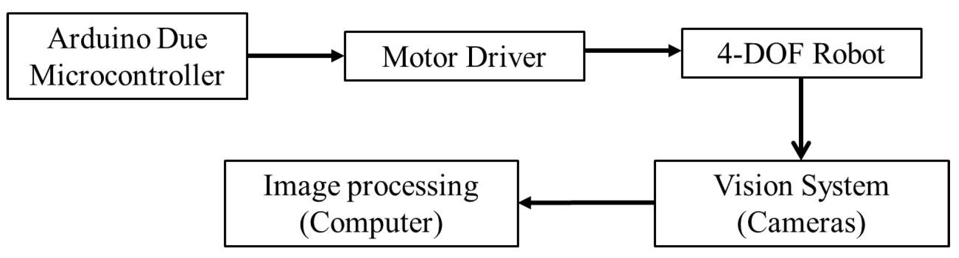
Through this experiment, the same test scenario that is conducted in the simulation is repeated to follow a circular track in the 3D-space while using the real manipulator. Figure 13 shows the system setup that is used to control our manipulator. The structure of the robot is made of Acrylonitrile Butadiene Styrene (ABS) material through 3D printing technique. Because our robot is a ceiling-mounted type robot, it is held on a 3D printed holder that is made of ABS material. The Arduino Due microcontroller is used in order to control the direction and position of our manipulator through motor drivers. Additionally, we used a breadboard with push-buttons and pull-down resistors to trigger different test scenarios. Because our manipulator is a miniaturized system with limited size, and it is difficult to attach internal sensors at each joint to detect the position of the end-effector ultimately. Hence, in this research, we suggested using non-contact sensors (16 Megapixel digital cameras) to detect the position of the end-effector. For this purpose, image processing techniques with the help of two cameras are used. The cameras are fixed at the front and the side of our manipulator to be able to find the position of the end-effector in the 3D-space. The end-effector is marked by a small blue ball, so that it would be easier to be distinguish through image processing techniques. Figure 14 shows the block diagram of our robot. The position of the ball representing the end-effector is determined by processing the videos that were obtained by the cameras. Both of the cameras at the front and the side work at the same time and capture the same experiment from different views.
4.2. Open-Loop Tracking Test
By applying the proper input signal to the joints of our manipulator, the position of the end-effector will change to follow a circular path. The proper joint angles required for this purpose are obtained in the previous section, as shown in Figure 12. Image processing techniques are used in order to track the end-effector location. The algorithm conducted in this research performs object detection and object tracking techniques of Matlab. Object detection is basically required to detect both locations of the center of rotation at each joint and the location of the end-effector at front and side views. Object detection technique of Matlab uses the minimum eigenvalue algorithm that was developed by Shi and Tomasi [16] to find feature points. Whereas, object tracking is used to detect and track the end-effector in the videos that were obtained by the front and side views cameras. The object tracking technique of Matlab uses the Kanade–Lucas–Tomasi (KLT) feature-tracking algorithm [17,18]. The algorithm is applied on the two synchronized videos of the two cameras.
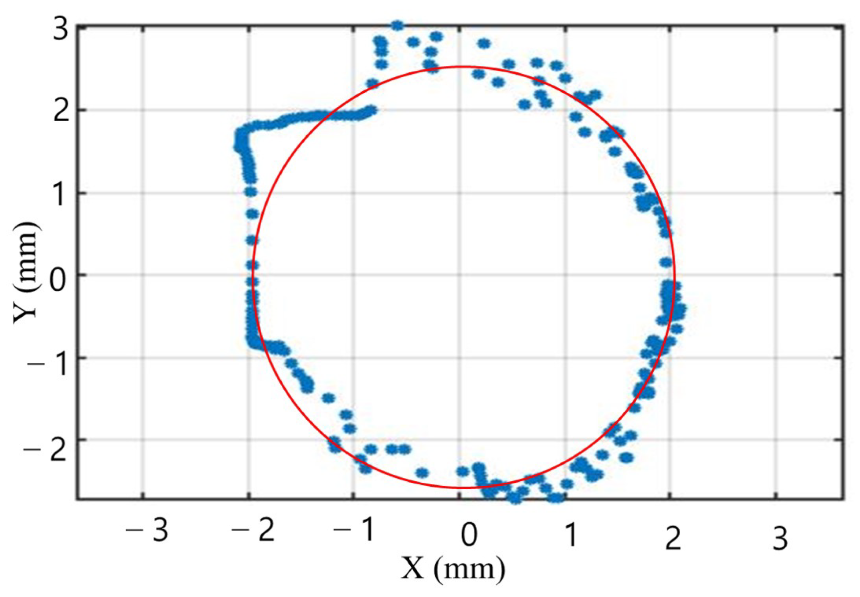
In this experiment, the input that is applied to the joints of the 4-DOF robot is generated while using sinusoidal functions, as shown in Figure 12. Figure 15 shows the actual path that the end-effector makes while applying open-loop control system. The generated path by the 4-DOF robot is smaller than the path that is generated in simulation and it suffers from few bumps. The main reason for this inexact response is that the simulation analysis did not consider the effect of gravity. Moreover, the friction existing in the current prototype of our 4-DOF mechanism limits the motion. In fact, the current structure is created by a low-cost 3D printing techniques with poor surface finish. Besides, the small size of our manipulator has space limitation to add bearings at the joints in order to fix the friction issues. However, although an open-loop control system is applied, a good response could be obtained in most of the generated circular track, except for moderate errors at some locations. However, having these mechanical errors, the performance of the system is still reasonable and proving the concept of operation of our manipulator.
5. Conclusions
In this paper, we introduced a novel dual-axis electromagnetic actuator that can be used in several application. The new actuator is a modular, light, and miniaturized actuator. Finite element analysis is conducted in order to study the performance of our EMA in terms of the generated torque and angle of rotation. Thus, it could achieve a torque of 100 mNm at simulation and 80 mNm through experiments for the same applied current. Whereas, it could achieve rotation of (≈0.2 rad) according to simulation and experimental work.
As an example study on our proposed EMA, two modules of our dual-axis EMA are connected together and employed in order to create a 4-DOF serial manipulator. Forward and inverse kinematic analyses are developed to numerically investigate the robot performance. A closed-form solution of the inverse kinematics problem is analytically obtained while using algebraic method. Using this inverse kinematics model, the end-effector of our manipulator can achieve any pose in the reachable workspace. Hence, the robot succeeded to follow a predefined circular track, which was randomly selected to test the inverse kinematics model. Eventually, we developed a prototype of our manipulator in order to validate its performance experimentally. Our manipulator is used to reproduce the predefined circular trajectory that was previously generated by simulation. The electromagnetic coils of our actuators are energized with the suitable electric current signal to achieve this circular trajectory. Through this experiment, we applied an open-loop controller and the performance was tested through image processing techniques. Although we used an open-loop controller in this experiment, our manipulator is still able to track the predefined trajectory with moderate errors.
In the future, closed-loop feedback control system can be implemented in order to enhance the system performance. The developed EMA has a great potential to be used in several applications. It can be utilized in legged or quadruped robotic applications if connected in parallel configuration. Whereas, multiple modules can be also connected in serial configuration to act as a snake-like robot with considerable flexibility. In this configuration, the main structure of the whole mechanism is supported on the ground and only active joints can be actuated.
Author Contributions
Conceptualization, N.A.M. and B.S.; methodology, N.A.M.; software, N.A.M.; validation, N.A.M., Y.K. and B.R.; formal analysis, N.A.M.; investigation, N.A.M.; resources, B.S.; data curation, N.A.M.; writing—original draft preparation, N.A.M.; writing—review and editing, B.S., Y.K. and B.R.; visualization, N.A.M.; supervision, B.S.; project administration, B.S.; funding acquisition, B.S., please turn to the CRediT taxonomy for the term explanation. All authors have read and agreed to the published version of the manuscript.
Funding
This research was supported by Basic Science Research Program through the National Research Foundation of Korea (NRF) funded by the Ministry of Education, Science and Technology (No. NRF-2017R1C1B5018324 and No. NRF-2020R1I1A3070333).
Institutional Review Board Statement
Not applicable.
Informed Consent Statement
Not applicable.
Data Availability Statement
Data supporting the findings of this study are contained within the article. Any further data required are available from the corresponding author upon request.
Conflicts of Interest
The authors declare no conflict of interest.
References
- Fu, Q.; Guo, S.; Huang, Q.; Hirata, H.; Ishihara, H. Development and Evaluation of Novel Magnetic Actuated Microrobot with Spiral Motion Using Electromagnetic Actuation System. J. Med. Biol. Eng. 2016, 36, 506–514. [Google Scholar] [CrossRef]
- Choi, H.; Choi, J.; Jeong, S.; Yu, C.; Park, J.; Park, S. Two-dimensional locomotion of a microrobot with a novel stationary electromagnetic actuation system. Smart Mater. Struct. 2009, 18, 115017–115023. [Google Scholar] [CrossRef]
- Yu, C.; Kim, J.; Choi, H.; Choi, J.; Jeong, S.; Cha, K.; Park, J.; Park, S. Novel Electromagnetic Actuation System for Three-Dimensional Locomotion and Drilling of Intravascular Microrobot. Sens. Actuators A-Phys. 2010, 161, 297–304. [Google Scholar] [CrossRef]
- Choi, H.; Jeong, S.; Go, G.; Lee, C.; Zhen, J.; Ko, S.Y.; Park, J.; Park, S. Equitranslational and axially rotational microrobot using electromagnetic actuation system. Int. J. Control Autom. Syst. 2017, 15, 1342–1350. [Google Scholar] [CrossRef]
- Li, D.; Niu, F.; Li, J.; Li, X.; Sun, D. Gradient-Enhanced Electromagnetic Actuation System with a New Core Shape Design for Microrobot Manipulation. IEEE Trans. Ind. Electron. 2020, 67, 4700–4710. [Google Scholar] [CrossRef]
- Tehrani, M.D.; Kim, M.O.; Yoon, J. A Novel Electromagnetic Actuation System for Magnetic Nanoparticle Guidance in Blood Vessels. IEEE Trans. Magn. 2014, 50, 1–12. [Google Scholar] [CrossRef]
- Niu, F.; Li, J.; Ma, W.; Yang, J.; Sun, D. Development of an Enhanced Electromagnetic Actuation System with Enlarged Workspace. IEEE/ASME Trans. Mechatron. 2017, 22, 2265–2276. [Google Scholar] [CrossRef]
- Manamanchaiyaporn, L.; Xu, T.; Wu, X. An Optimal Design of an Electromagnetic Actuation System towards a Large Homogeneous Magnetic Field and Accessible Workspace for Magnetic Manipulation. Energies 2020, 13, 911. [Google Scholar] [CrossRef] [Green Version]
- Lu, H.; Zhu, J.; Lin, Z.; Guo, Y. An inchworm mobile robot using electromagnetic linear actuator. Mechatronics 2009, 19, 1116–1125. [Google Scholar] [CrossRef] [Green Version]
- Kohls, N.; Dias, B.; Mensah, Y.; Ruddy, B.P.; Mazumdar, Y.C. Compliant Electromagnetic Actuator Architecture for Soft Robotics. IEEE Int. Conf. Robot. Autom. (ICRA) 2020, 9042–9049. [Google Scholar] [CrossRef]
- Zou, Y.; Zhang, W.; Zhang, Z. Liftoff of an Electromagnetically Driven Insect-Inspired Flapping-Wing Robot. IEEE Trans. Robot. 2016, 32, 1285–1289. [Google Scholar] [CrossRef]
- Ko, Y.; Na, S.; Lee, Y.; Cha, K.; Ko, S.Y.; Park, J.; Park, S. A jellyfish-like swimming mini-robot actuated by an electromagnetic actuation system. Smart Mater. Struct. 2012, 21, 1–10. [Google Scholar] [CrossRef]
- Shin, B.H.; Lee, K.-M.; Kim, Y. Miniaturized Dual Electromagnetic Oscillatory Actuator. Adv. Sci. Technol. Lett. 2014, 46, 56–59. [Google Scholar]
- Spong, M.W.; Hutchinson, S.; Vidyasagar, M. Forward Kinematics: The Denavit-Hartenberg Convention. In Robot Modeling and Control, 2nd ed.; Wiley: New York, NY, USA, 2005; pp. 61–82. [Google Scholar]
- Siciliano, B.; Sciavicco, L.; Villani, L.; Oriolo, G. Inverse Kinematics Problem. In Robotics: Modelling, Planning and Control, 1st ed.; Springer: Berlin/Heidelberg, Germany, 2008; pp. 90–100. [Google Scholar]
- Shi, J.; Tomasi, C. Good Features to Track. In Proceedings of the IEEE Conference on Computer Vision and Pattern Recognition, Seattle, WA, USA, 21–23 June 1994; pp. 593–600. [Google Scholar]
- Lucas, B.; Kanade, T. An Iterative Image Registration Technique with an Application to Stereo Vision (IJCAI). In Proceedings of the 7th International Joint Conference on Artificial Intelligence, Vancouver, BC, Canada, 24–28 August 1981; pp. 674–679. [Google Scholar]
- Tomasi, C.; Kanade, T. Detection and Tracking of Point Features. Int. J. Comput. Vis. 1991. [Google Scholar]
Figure 1.
Single dual-axis electromagnetic actuator module.

Figure 2.
Description of the generated Lorentz force (B: magnetic field, F: Lorentz force, T: torque generated around the axis of rotation, ⊗: current in, ⊙: current out).
Figure 2.
Description of the generated Lorentz force (B: magnetic field, F: Lorentz force, T: torque generated around the axis of rotation, ⊗: current in, ⊙: current out).

Figure 3.
Finite element simulation results of a single module of our electromagnetic actuator.

Figure 4.
Experimental setup for the characterization the developed electromagnetic actuator.

Figure 5.
Simulation and experimental results for the torque generated with respect to the applied current.
Figure 5.
Simulation and experimental results for the torque generated with respect to the applied current.

Figure 6.
Simulation and experimental results for the torque generated with respect to the angle of rotation.
Figure 6.
Simulation and experimental results for the torque generated with respect to the angle of rotation.

Figure 7.
Mechanical structure of the 4-DOF manipulator.

Figure 8.
Prototype of the 4-DOF robot.

Figure 9.
Workspace of the 4-DOF manipulator with joint angles limited to () (dimensions in mm).

Figure 10.
End-point trajectory achieved by inverse kinematics where Z = mm and radius is mm (dimensions in mm).
Figure 10.
End-point trajectory achieved by inverse kinematics where Z = mm and radius is mm (dimensions in mm).

Figure 11.
Side-view of the robot structure while following a circular trajectory in the horizontal plane.
Figure 11.
Side-view of the robot structure while following a circular trajectory in the horizontal plane.

Figure 12.
Joints’ angles required to achieve a circular trajectory with radius of mm and at mm (note, and are identical).
Figure 12.
Joints’ angles required to achieve a circular trajectory with radius of mm and at mm (note, and are identical).

Figure 13.
System setup of the 4-DOF robot.

Figure 14.
Block diagram of the 4-DOF open-loop control system.

Figure 15.
Actual path achieved by the end-effector while applying open loop control system.


Table 1.
Denavet–Hartenberg (D-H) parameters of the 4-DOF robot.
| Link | d | a | ||
|---|---|---|---|---|
| 1 | 0 | 0 | ||
| 2 | 0 | 0 | ||
| 3 | 0 | 0 | ||
| 4 | 0 | 0 |
Publisher’s Note: MDPI stays neutral with regard to jurisdictional claims in published maps and institutional affiliations. |
© 2021 by the authors. Licensee MDPI, Basel, Switzerland. This article is an open access article distributed under the terms and conditions of the Creative Commons Attribution (CC BY) license (http://creativecommons.org/licenses/by/4.0/).
Share and Cite
MDPI and ACS Style
Mansour, N.A.; Shin, B.; Ryu, B.; Kim, Y. Development of a Novel Miniaturized Electromagnetic Actuator for a Modular Serial Manipulator. Actuators 2021, 10, 14. https://0-doi-org.brum.beds.ac.uk/10.3390/act10010014
AMA Style
Mansour NA, Shin B, Ryu B, Kim Y. Development of a Novel Miniaturized Electromagnetic Actuator for a Modular Serial Manipulator. Actuators. 2021; 10(1):14. https://0-doi-org.brum.beds.ac.uk/10.3390/act10010014
Chicago/Turabian StyleMansour, Nader A., Buhyun Shin, Bongjo Ryu, and Youngshik Kim. 2021. "Development of a Novel Miniaturized Electromagnetic Actuator for a Modular Serial Manipulator" Actuators 10, no. 1: 14. https://0-doi-org.brum.beds.ac.uk/10.3390/act10010014
Note that from the first issue of 2016, this journal uses article numbers instead of page numbers. See further details here.