1. Introduction
Mechanisms for space applications typically need to fulfil additional requirements due to the extreme operational environment. Deployment mechanisms for antenna [
1], solar panels [
2], or docking elements have to be light and elastic [
3] but at the same time they need to damp vibrations. In space, any vibrating structure needs an additional damping mechanism in order to mitigate vibrations after deployments or operations. Conventional damping elements as friction or viscous dampers [
4] can hardly be applied in space systems since oils, metallic chips, and other type of dust particles can damage precision optical components and delicate sensors. Therefore, other types of mechanical solutions providing spring-damping behaviour must be explored. Similar cleanliness requirements can be found in mechanical systems for surgical applications [
5].
Although metal springs are extensively applied in mechanical systems, their vibration damping capacity is limited. Moreover, they consume metal and cause vibration and noise, resulting in negative effects on the reliability and stability of the system. Even more, metal springs are liable to suffer from fatigue and permanent plastic deformation, reducing the reliability of the system. Besides conventional springs, metal springs are normally constructed as a bunch of metal wires winded up to create a multilayer coaxial strand following the helical direction. Stranded-wire helical springs show higher damping capacity and longer lifetime under certain dynamic applications [
6]. However, this damping capacity comes from the fretting of wires among themselves, which generates chips and wear [
7]. Thus, these type of metal springs, even in dampers, can generate issues for optical space instruments. Therefore, it can be worthwhile to explore more exotic solutions in order to provide mechanical components with elastic response and damping capacity adequate for application in space mechanisms deployment.
Innovative solutions based on magnets can be an option for space mechanisms applications. High performant magnetic systems appeared after the development of high magnetic product magnets based on Nd-Fe-B alloys [
8,
9]. This type of new magneto-mechanisms have in common some unique features: cleanness, oil-free, reliability, low wear, no power consumption, long life, and low noise [
10,
11,
12,
13,
14,
15,
16,
17,
18,
19,
20].
Among these new magneto-mechanisms, magnetic springs are widely used as an auxiliary element of energy harvesting systems [
21,
22,
23]. In magnetic springs, the damping is negligible and the magnetic spring only acts as a stiffness element. Other applications of magnetic springs are in combination with active magnetic suspension [
24,
25,
26,
27,
28]. In these cases, they provide contactless support of at least one degree of freedom and again without damping. A magnetic spring has been also been used in negative stiffness vibration dampers [
29,
30]. However, these solutions are not valid for space applications where cleanness is required. Another option are magnetorheological dampers, but although they offer very good mechanical performance in terms of damping and reliability [
31,
32], they still require oils for their operations and thus, are not very convenient for space applications.
Eddy current dampers are a good solution as they are clean and efficient dampers. Eddy current dampers were successfully used in space mechanisms [
33,
34]. In these cases, the damping element is combined with other elastic components such as a metal spring or the structure itself. Eddy current damping has also been used in other industrial applications like in rotary sensors or shock absorbers [
35,
36,
37]. The most performant eddy current damper ever done is the device published in [
12,
13]. This outstanding eddy current damper includes a magnetic linear gear to amplify the input vibration, which maximizes, through impedance matching, the effectiveness of the damper. The damping density of this device is the largest ever achieved for an eddy current damper demonstrating a value of 8.4 MN s m
−4, even operating at high temperatures.
In the present work, we propose a simpler device that integrates a passive magnetic spring and an eddy current damper in a single device. The key point is to get the benefit of the moving magnets used in the magnetic spring to couple their magnetic field with a conductive element to provide damping capacity. More specifically, we propose to use ring-shaped NdFeB magnets inserted on an aluminium rod, which acts as both an eddy current dissipater and plain bearing guide. In this way, the whole device can be more compact, lighter, oil-free and reliable, therefore very adequate for space applications.
In this article, the mechanic and magnetic design of the device is described in detail. A dynamic model considering eddy current and Coulomb damping is presented and analyzed. A prototype of the magnetic parts of the devices was manufactured and assembled. The experimental static and dynamic characterization provide a validation of the model used for the dynamic response and behaviour of the device. This information can be useful for considering this device in future space and other type of mechanical applications.
2. Mechanical and Electromagnetic Design and Analysis
2.1. Mechanical Design
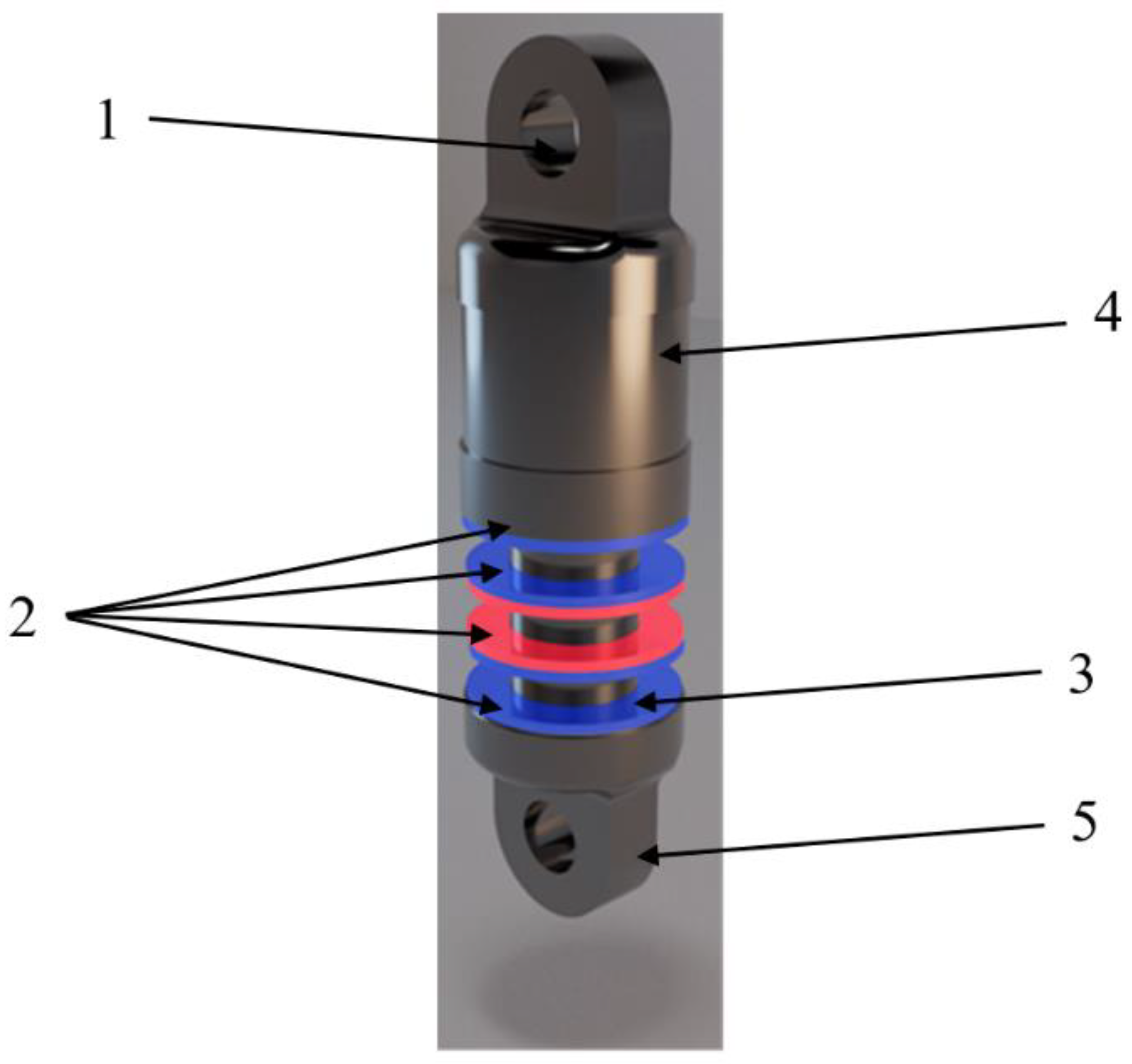
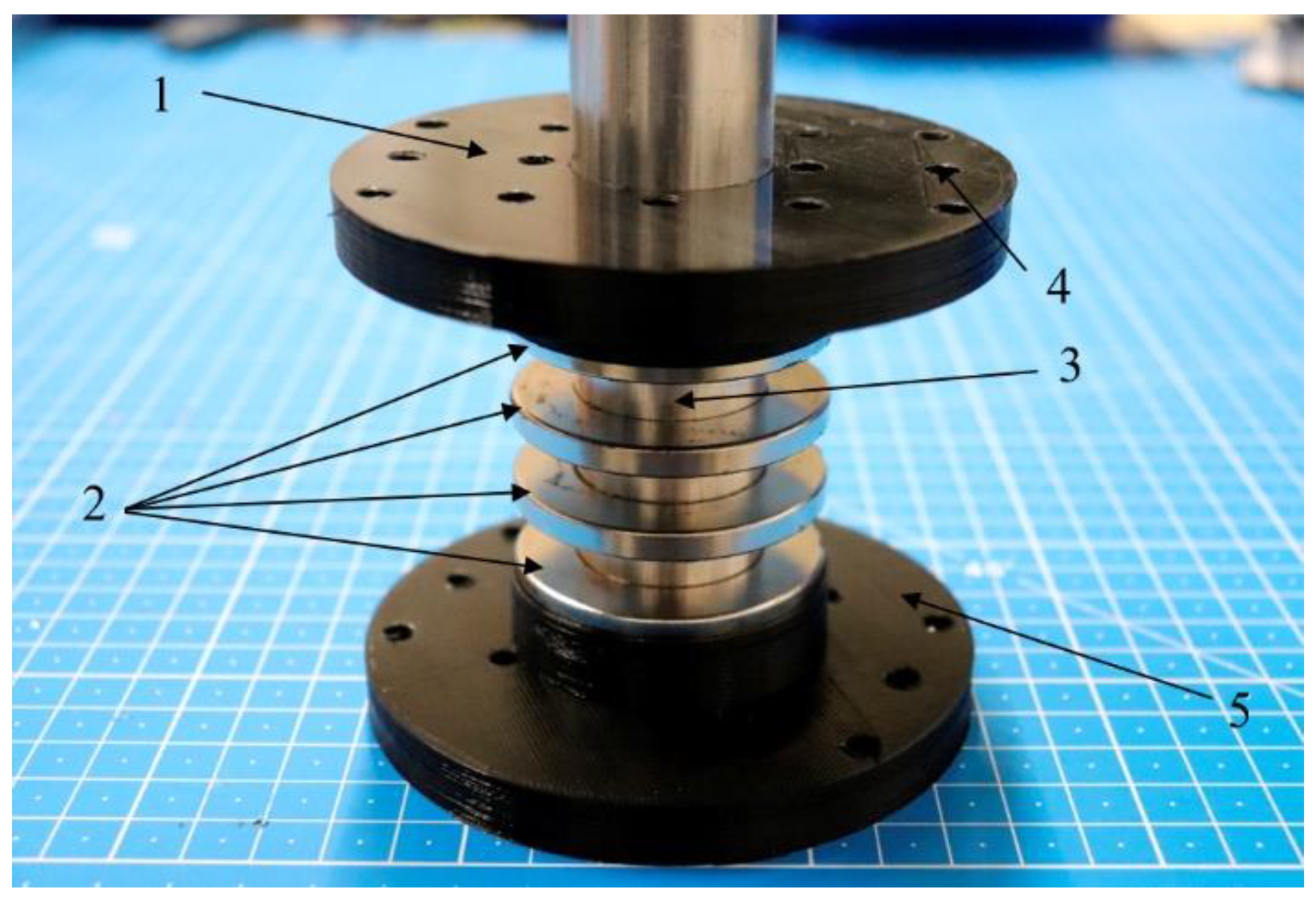
The design of the device is simple and straightforward, as shown in
Figure 1. Two spherical ends, (1) and (5), which are used for external mechanical connections, enclose the magnetic spring and the eddy current damper. An inner cylindrical aluminum rod (3) serves as guide for the magnets’ motion as well as a conductive element for the eddy current dissipation. A set of ring-shaped magnets (2) are distributed along this aluminum rod. The number of magnets can be easily changed from 4, to 3 and 2 within the same device, depending on the damping and stiffness requirement. The top end is connected to the top magnet through a hollowed cylindrical linking part (4). The hollowed cylinder is needed to allow the motion of the magnets from the magnetic spring and to host the conductive layer for extreme spring operation positions. Any external mass or element can be connected to the two spherical ends through two corresponding bolts or axles.
The whole device was designed to be as light and compact as possible and to maximize the damping capacity. The design allows three magnetic topologies with two, three, and four magnets aligned along the conductive rod in alternant magnetization directions. Empty axial space in the linking rod permits the full compression of the magnetic spring. Different operation points and preload conditions could be defined by using limiting bulks in the linking rod. The inner cylindrical rod is also hollowed to alleviate mass, but with a thickness large enough to generate all the tangential eddy currents that maximize the damping; see
Figure 1.
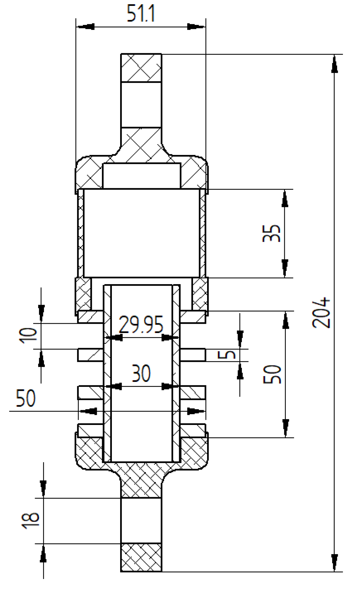
The device has a total size of 204 mm length and 51.4 mm diameter, including top and bottom ends. Dimensions are shown in
Figure 2 for the four magnets configuration. The main material in the device is aluminum 7075. It permits a reduced total mass of only 517 g in case of four magnets. Permanent Magnets are made of NdFeB with quality grade of N38H with axial magnetization direction. According to the manufacturer, the quality assures a magnetic remanence of 1.23–1.26 T and a coercivity of 899 kA/m at a maximum operational temperature of 120 °C (limit for most space applications). It is important to note the 0.05 mm diametrical clearance between magnets and aluminum inner rod that assures the correct linear guiding while preventing the rotation of magnets; see
Figure 2. Detailed list of materials, weight, and dimensions are given in
Table 1.
Besides the mechanical and geometrical design, specific detailed analysis linking magnetic behavior with dynamical parameters are done. Stiffness, eddy current damping, and friction Coulomb damping were estimated during the design phase.
2.2. Simulation of Stiffness—k
Selection of the magnets and conductive rod element was done after magnetic simulation. The objective of the design was to maximize the stiffness and damping capacity of the system while keeping a low total weight. Moreover, other considerations such as manufacturability and simplicity in assembly were taken into account.
All the simulations were performed using ANSYS Electromagnetic Desktop software v2019 R2. This is a Finite Element Model (FEM) software for electromagnetics solutions. It includes a magnetostatics and transient solver. For simulation of the stiffness, the magnetostatics solver is used. The magnetostatics solution is achieved following two Maxwell’s equations:
and
with the following relationship for each material:
where
B is the magnetic field density,
H is the magnetic field intensity,
J is the current density,
Mp is the permanent magnetization
µ0 is a constant of permeability of vacuum and
µr corresponds to the relative permeability. The solver obtains the magnetic field distribution produced by a spatial distribution of objects with permanent magnetization [
38] and a combination of DC current densities. All the simulations were run on a computer with Intel Core i4-4690 and 8 Gb of RAM memory.
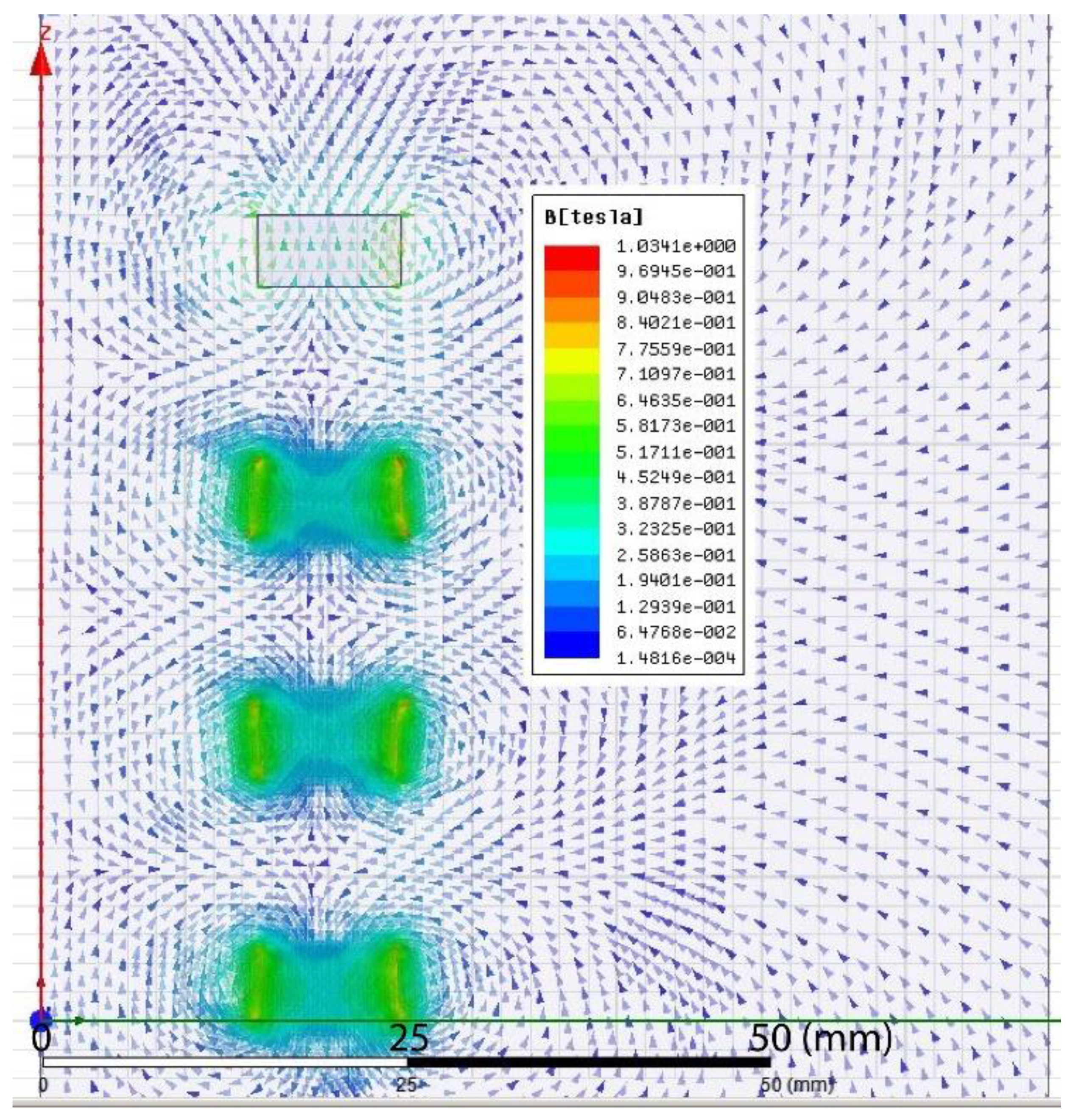
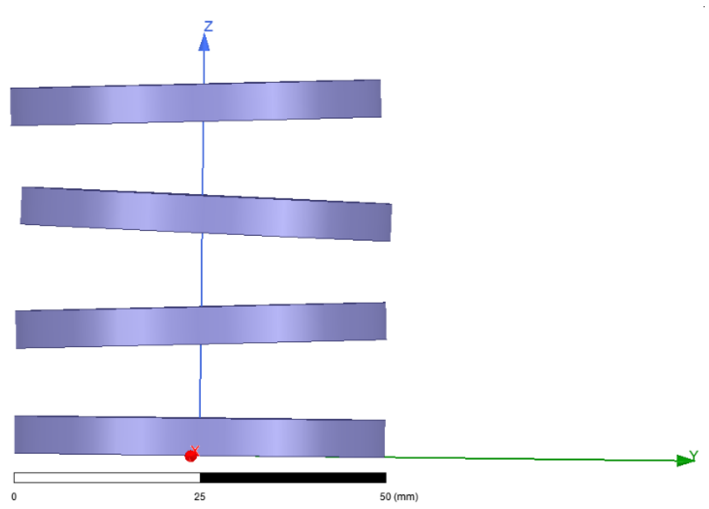
The FEM model is based on 2D axisymmetric geometric as the symmetry of the device allows to do. By using 2D models, the computation time is drastically reduced. Static simulations of two, three, and four ring-shaped magnets were done in order to simulate the magnetic field, as shown in
Figure 3. The magnetic field generated has minimum values in the middle of the separation distance of the magnets because magnets are oriented in opposite poles configuration. The repulsion of the magnets by pairs is what generates the stiffness of the system. When there is no load, magnets tend to be in the largest separation distance, limited by bulks limits of the mechanical structure.
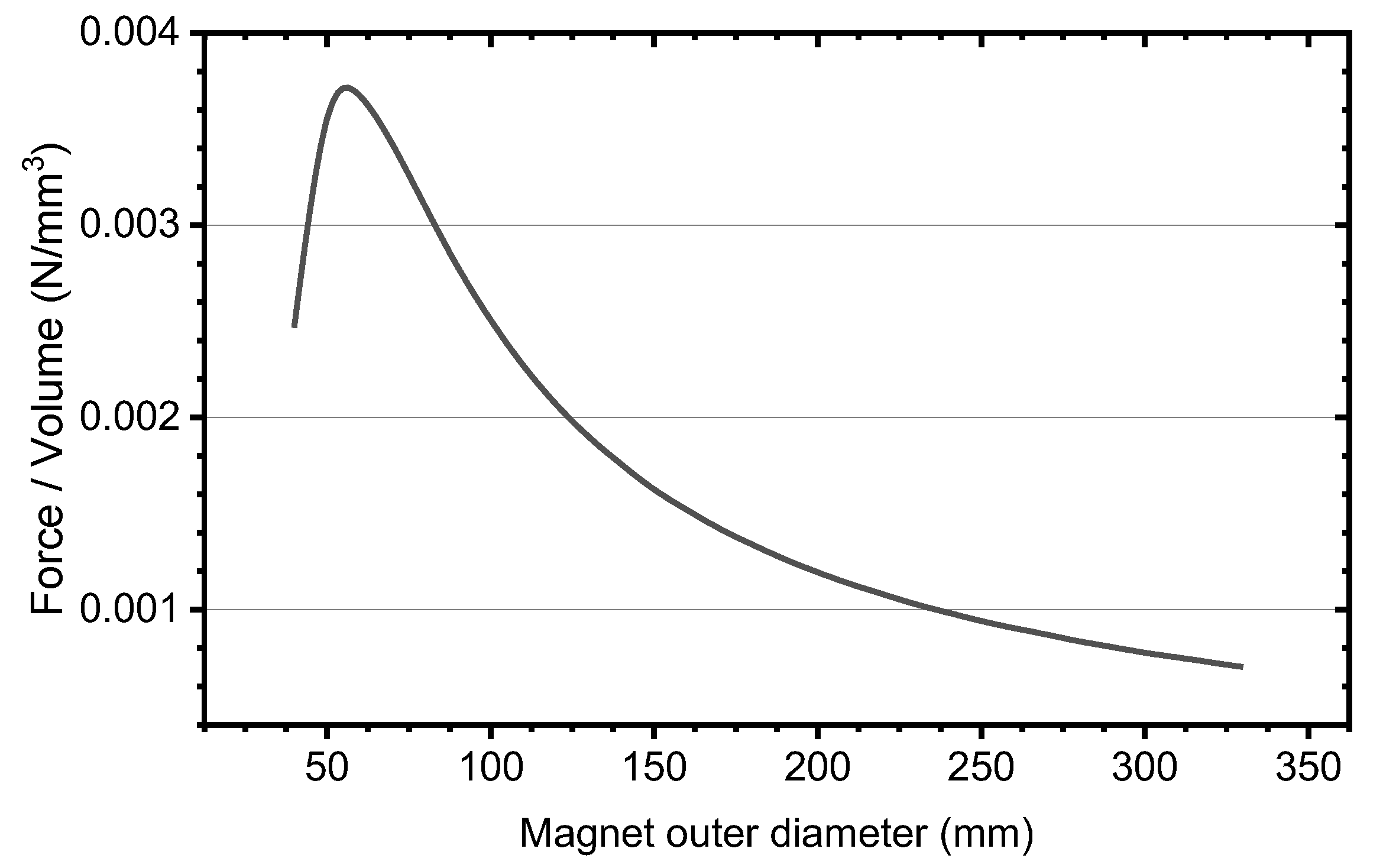
One of the main targets of any mechanical system for spaces is to optimize the compactness of the system, i.e., to achieve the desired performance with the minimum size/volume. We used a parameter 2D axisymmetric model to obtain the Force and magnet volume ratio as a function of the outer diameter (see
Figure 4). From this analysis, we determined that an optimal outer diameter for the magnet would be around 50 mm.
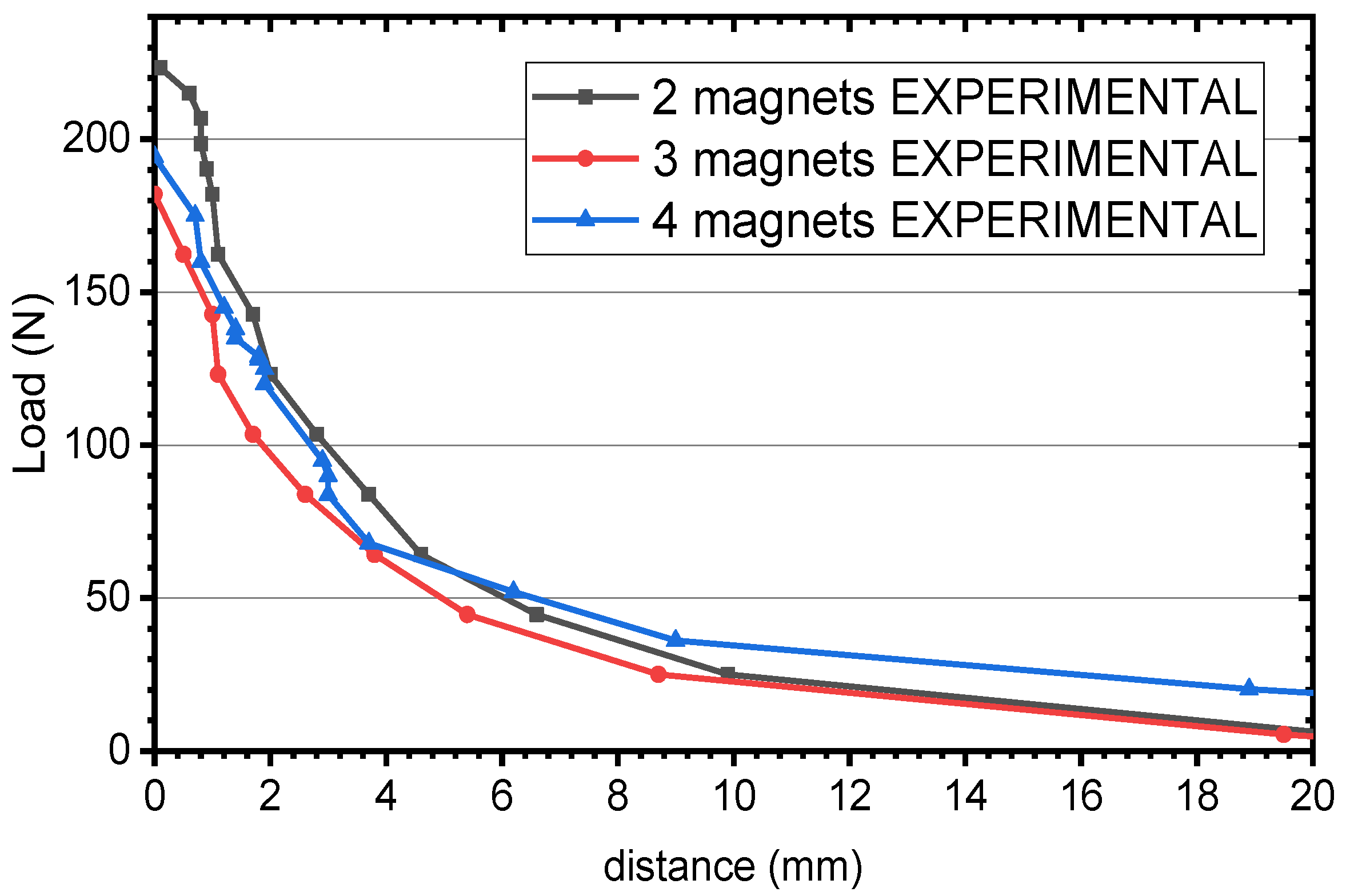
From the magnetic field simulation, in a post-processing step, forces between the different magnets for different separation distances are calculated by the virtual forces method. The most useful value is the force acting on the magnet at the top of the stack since this is the force that the system could exert against an external load. From these force calculation results, the stiffness of the system as a function of the distance between magnets poles can be derived. Next,
Figure 5 presents the relationship between repulsion force and separation distance of magnets faces for the three configurations: 2, 3, and 4 magnets. It is not possible to just simulate a pair of magnets and extrapolate since linear superposition principle, widely used in mechanics, is not applicable to magnetic fields. The results for the stiffness are also shown in
Figure 5.
It is significant that the stiffness of the magnetic spring is not linear, but it progressively increases with decrease of distance between the magnets. This can be explained since magnetic force interaction of two dipoles depend inversely on the distance to the fourth power. It should be noted that stiffness and maximum load is quite similar for all three cases. Intermediate magnets, as they all have the same quality, just provide a continuity of the force interaction between the top and bottom magnets.
From
Figure 5, we can determine that a static force of 19.36 N must be applied in order to keep a distance of 10 mm with four magnets configuration as intended from design. This leads to a stiffness of 1936 N/m in the surroundings of 10 mm separation distance.
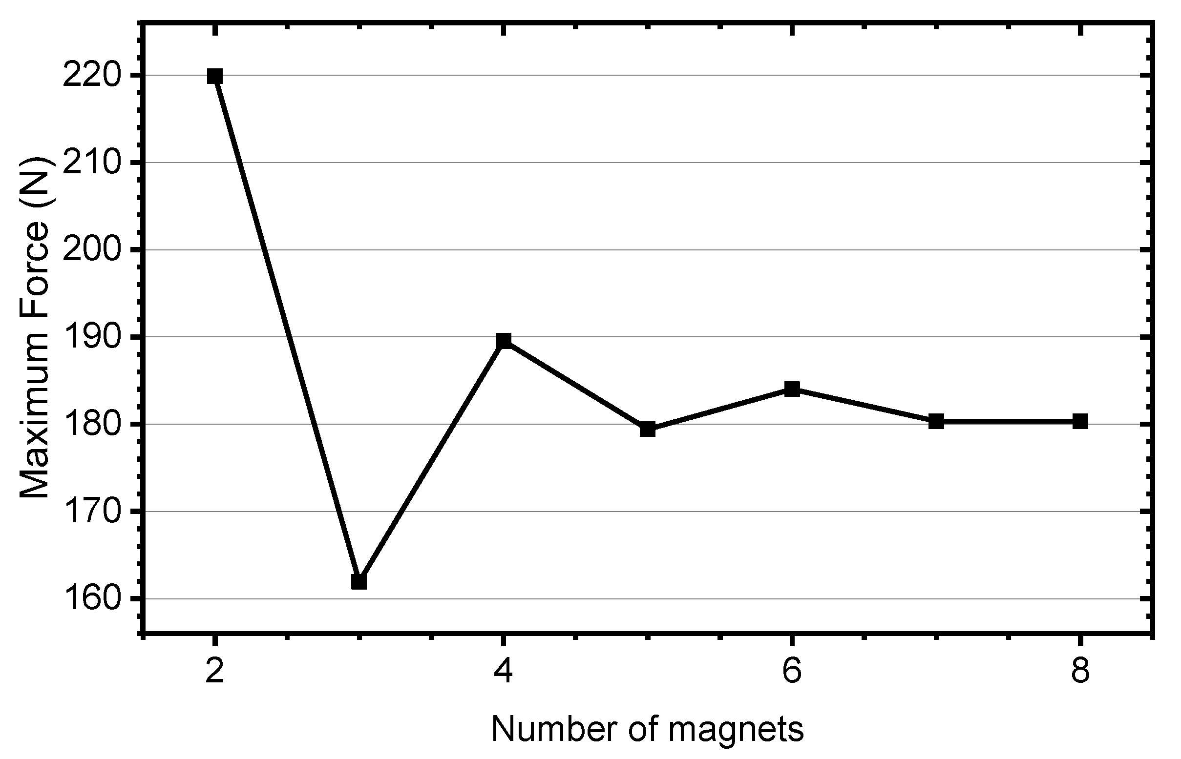
As an additional result of the simulation, a larger number of magnets was considered. Maximum expected force was simulated for up to eight magnets in opposite magnetization directions. The behavior is shown in
Figure 6. The maximum force oscillates for 2 to 6 magnets and then, it gets constant around 180 N for a larger number of magnets. While the number of magnets is reduced (2, 3 and 4), there is a direct influence between the top and bottom magnets among themselves. However, when the number of magnets increases, the influence between the top and bottom magnets is reduced, affecting only the more adjacent ones.
2.3. Simulation of Eddy Current Damping—ced
When a magnetic field varies inside an electrical conductor, the motion generates eddy currents in the electrical conductor. These currents rotates in such a path that an opposing magnetic field is created, appearing the so called Lorentz forces. These forces result in damping effect of the magnets motion and produces heat in the electrical conductor. The total energy transferred to the conductor is equal to the variation of kinetic energy of the magnets. Power losses per unit mass can be calculated, under assumptions of uniform material, uniform magnetic field, and null skin effect; as proportional to:
where
P is the power lost per unit mass (W/kg),
f is the frequency (Hz) of the oscillation, or variation, of the magnetic field applied and
a is a constant depending on the material conductivity, magnetic field of the magnet and geometrical dimensions.
Equation (2) is valid only in the quasi-static conditions, where the frequency of the magnet movement is low enough not to generate skin effect; in such a way that electromagnetic waves fully penetrates the material. For the case of the proposed device, skin depth is estimated in the range of 10 mm, much larger than the area where eddy currents will be generated. Therefore, the assumption of Equation (2) is correct. Power losses of a viscous damper can be described as:
where
FL is damping force (Lorentz force), and
v is the velocity of the moving suspended mass. By linking mechanical losses and eddy current losses, we can demonstrate that:
Moreover, as oscillatory motion frequency is directly proportional to the amplitude of the linear speed as
, we can determine that the damping force-speed ratio is a constant value,
ced, depending on the electromagnetic behavior of the magnet:
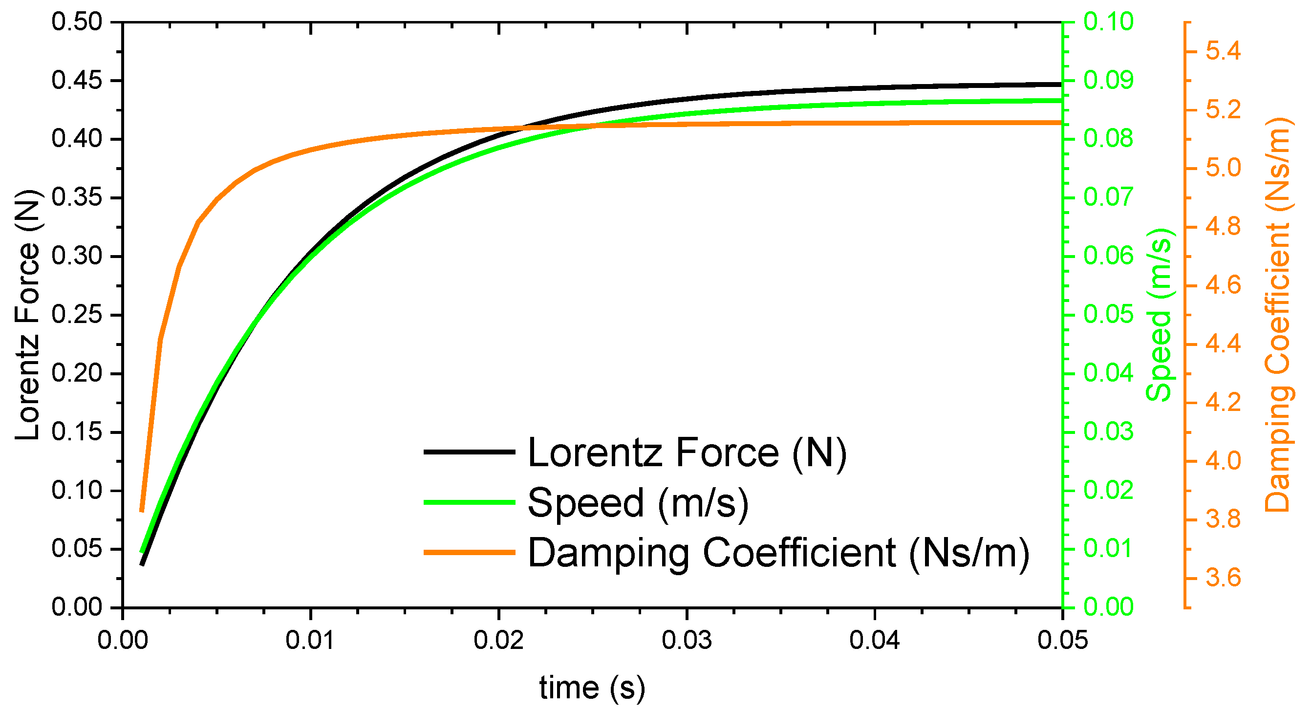
Dynamic simulations of the magnet along the conductive rods were done using a transient 2D FEM solver. Different speeds were simulated. For the dynamic simulations, just a single magnet along the aluminum rod is included since eddy currents are significant only in the surroundings of the magnet, thus magnetic interaction of adjacent magnets is negligible.
Figure 7 presents the Lorentz force and linear speed for a specific case as an example. With the asymptotic value of the force, we can determine the damping coefficient. By simulating Lorentz force at different speeds, we have found that for all of them, the damping force-speed ratio is constant with a total value of 5.15 Ns/m. This value applies for the two magnets case. For three magnets configuration, the damping coefficient is 10.30 Ns/m and for the four magnets configuration, the damping coefficient is 15.45 Ns/m. Thus, it is expected that the prototype with four magnets will dissipate faster than the prototype with two or three magnets since a larger amount of eddy currents are generated in total.
2.4. Estimation of Coulomb Friction Damping Coefficient—cCou
Inner conductive aluminum rods serve as an eddy current dissipater but also as a mechanical guide for the magnets’ linear motion. Linear guiding unavoidably generates friction forces when moving. Thus, it is necessary to analyze the expected friction forces during the damping of the magnet motion.
The resistance friction force,
Ff, dissipates energy as
, where
X is the displacement of the moving element. The energy dissipated by the friction damping force can be linked with an equivalent viscous damping coefficient for Coulomb friction,
cCou, using the oscillatory angular speed
ω as [
39]:
For the free vibration test, oscillatory angular speed ω will correspond to natural radian frequency and displacement will be considered as ±2 mm. Thus, in order to estimate damping coefficient cCou, we need to estimate friction force.
Friction force only appears if magnets frets against the inner rod. In an ideal situation, where magnets are perfectly aligned axially and radially, the force acting on the magnets in the radial direction would be zero, leading to a null normal force, thus no friction. However, as there is a small 0.05 mm diametric clearance between the inner conductive rod outer radius and the magnet inner radius, magnetic torque between magnets tends to tilt magnets creating a normal force between the magnet and the inner conductive rod.
By simple geometrics, it can be demonstrated that a diametric clearance of 0.05 mm allows the magnets to rotate an angle of maximum 0.55° in a direction perpendicular to the revolution axis. Therefore, magnetostatics simulations of the torque acting on each moving magnet for a 0.55° rotation were done, as shown in
Figure 8. These torques are transformed to normal forces between the magnets and inner conductive rod by using the relation of
(pair of forces). These normal forces multiplied by an estimated friction coefficient between aluminum and NdFeB in solid lubricated conditions give the total friction forces acting on the device. The simulation was done for each configuration (2, 3, and 4 magnets). The 3D simulation model used for torque calculation in 4 magnets configuration in shown in
Figure 8. Results of the calculations of Coulomb friction damping coefficients are summarized in
Table 2.
By using Equation (4), the total damping coefficients are estimated for each case. We have analyzed all the static and dynamic parameters determining the expected performance of the suspension. A summary of the expected dynamical parameters is presented in
Table 3 for each configuration operating at 10 mm distance magnet separation.
2.5. Dynamical Model
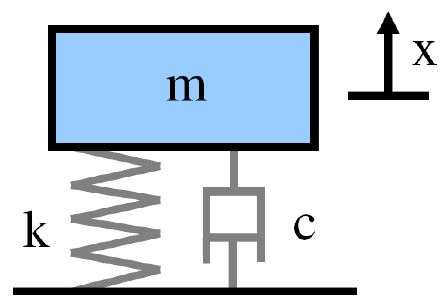
The dynamical model of the device follows the conventional damped harmonic oscillator equations as applicable for any spring-viscous damping suspension. It includes stiffness provided by the magnetic spring, eddy current viscous damping given by the magnet-conductive rod magnetic interaction and equivalent viscous Coulomb friction damping due to mechanical fretting of the magnet against the conductive rod. It has been considered that oscillation amplitude is very limited so that stiffness can be considered constant within the motion range. Therefore, the linear model is valid. Moreover, the model includes the corresponding suspended mass m. As the system has only one Degree Of Freedom (DoF), x axis—vertical direction, the model is simple, and it can be described as shown in
Figure 9.
The balance of forces for the damped harmonic oscillator model is then:
In the case of a sinusoidal driving force,
, this can be rewritten into the form:
where
is the undamped angular frequency of the oscillator or natural radian frequency,
is the damping ratio,
F0 is the amplitude of the driving motion, and ω is the frequency of the sinusoidal driving motion.
A general solution is the sum of a steady state part that is not depending on the initial conditions and a transient part that depends on initial conditions. The general solutions depend only on the driving amplitude F0, driving frequency ω, undamped angular frequency ω, and the damping ratio .
The steady-state solution returns as proportional to the driving force with phase shift:
where
is the absolute value of the impedance or linear response function, and
is the phase of the oscillation relative to the driving force.
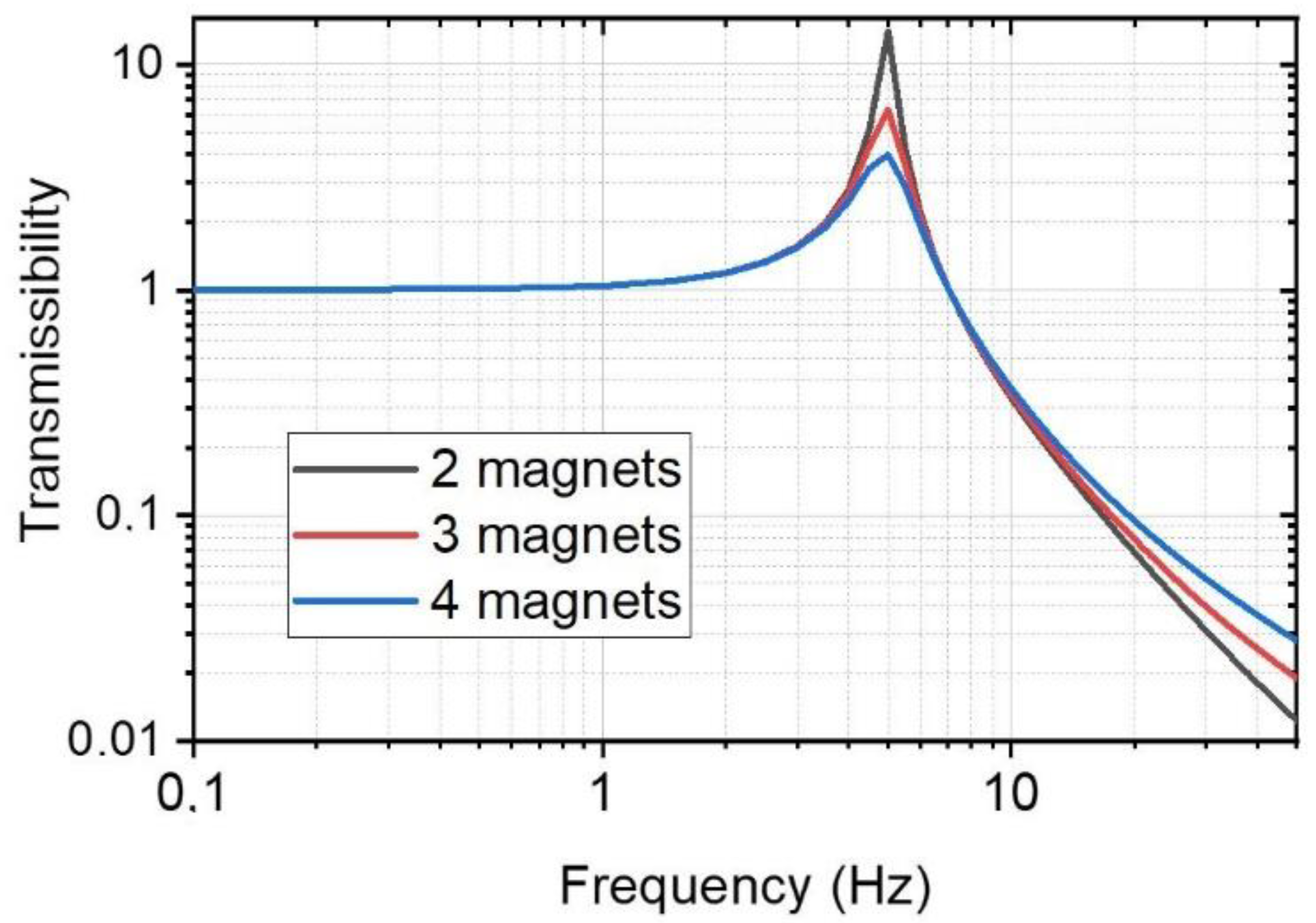
Transmissibility represents the ratio of the amplitude of the force transmitted to the supporting structure to that of the exciting force. From previous equations, the vibration transmissibility from top to bottom end can be described as:
By using this model, acceleration measurements and a known suspended mass; we can determine damping ratio of the system and its natural frequency experimentally.
3. Prototype Manufacturing and Testbench Set-Up
3.1. Prototype Manufacturing and Assembly
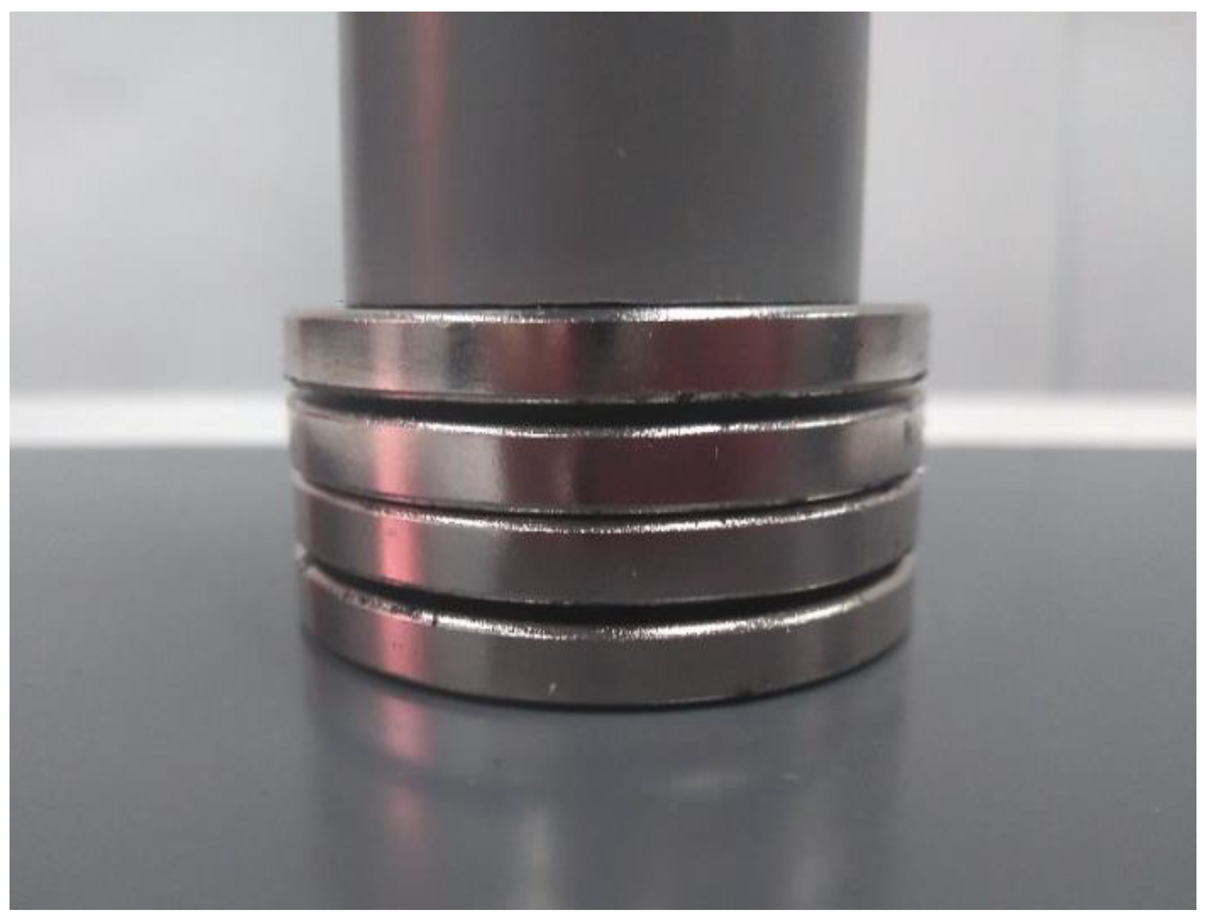
A simplified prototype was manufactured and assembled. Permanent magnets made of NdFeB N38H were purchased from HKCM Company (Germany), while the conductive inner aluminum rod and baseplate were manufactured at Universidad de Alcalá mechanical workshop.
Figure 10 shows a photograph of the different parts in the assembled configuration. Accurate tolerance adjustments between the magnets’ inner radius and inner cylinder were done in order to provide smooth displacement, reducing friction while avoiding wedge blockings. A clearance of just 0.05 mm between the magnet’s inner radius and rod outer radius is achieved. Adapted top and bottom ends were 3D printed including threaded holes to attach the accelerometer and the suspended mass.
3.2. Measurement System Set-Up and Data Analysis Procedure
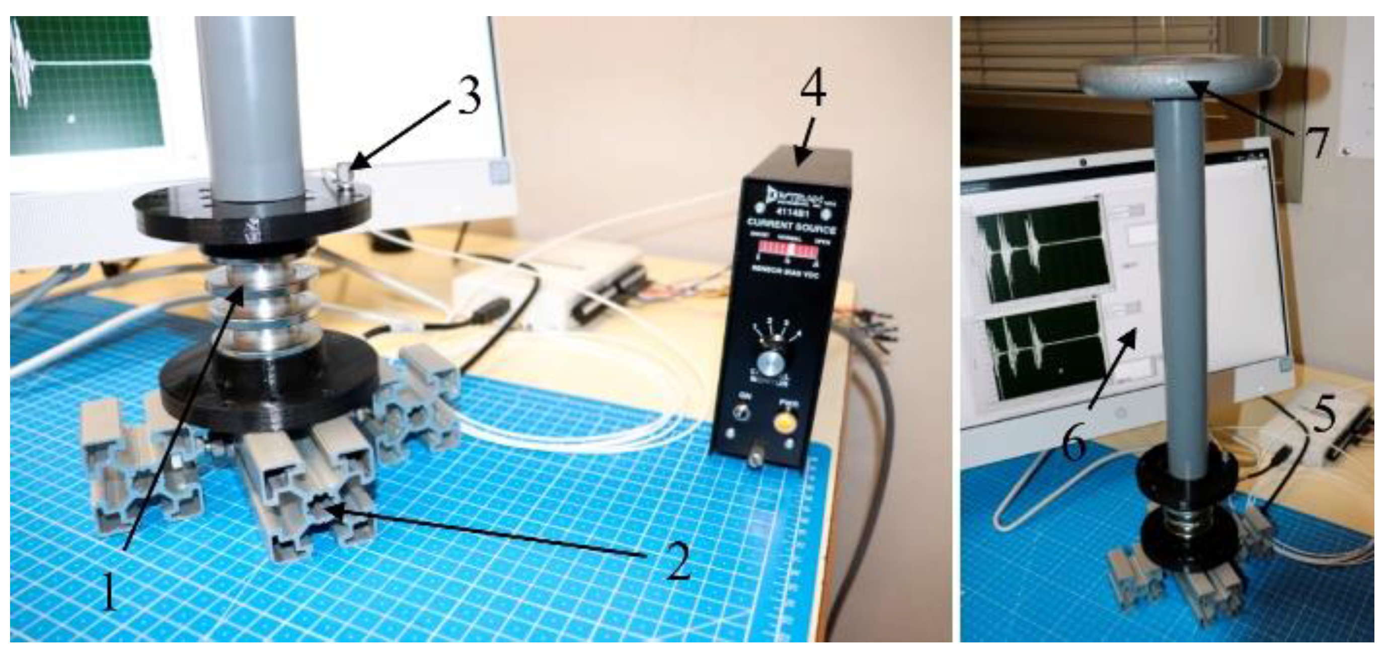
The measurement test bench was composed of a baseplate, a suspended mass, an accelerometer, a current source and signal conditioning for the accelerometer, a data acquisition system, and a software to register and analyze the measurements.
The test prototype was attached through the bottom end to a wider rigid baseplate. An uniaxial accelerometer was connected to the top end of the prototype. Above the top end, a suspended mass m of 2 kg was placed. The accelerometer was powered through a coaxial wire connected to the current power source. Then, by using BNC connectors, the output voltage of the accelerometers was read by a data acquisition card and the data were registered and treated in a personal computer. All the equipment are shown in
Figure 11.
The accelerometer used was an IEPE uniaxial 3035B model from DYTRAN with a sensitivity of 100 mV/g, frequency response of 0.5 to 10,000 Hz, and 2.5 g of mass. Current source was also from DYTRAN, model E4114B1, with an adjustable output current between 2 and 20 mA. Measurements were taken using a DAQ system USB-6211 from National Instruments and registered by means of a personal computer and Labview software. Measurement of the voltage provided by the accelerometers were done using a fixed number of 10,000 samples at a sampling frequency rate of 1 kHz, i.e., 10 s of continuous registering,
Figure 11.
Static tests were used in order to determine the stiffness at different magnet separation distance. The procedure was straightforward: addition of different masses above the device and by measuring the separation distance, load and stiffness were obtained. A similar procedure was used for the three-magnets configuration.
The dynamic tests were done in free vibration mode. An initial manual excitation was applied in the mass, pushing the mass from its initial position to a lower position, a separation distance of 8 mm between magnets. Then, at this position, the registration was started, and the mass released to vibrate freely. The same test procedure was done for all the configurations.
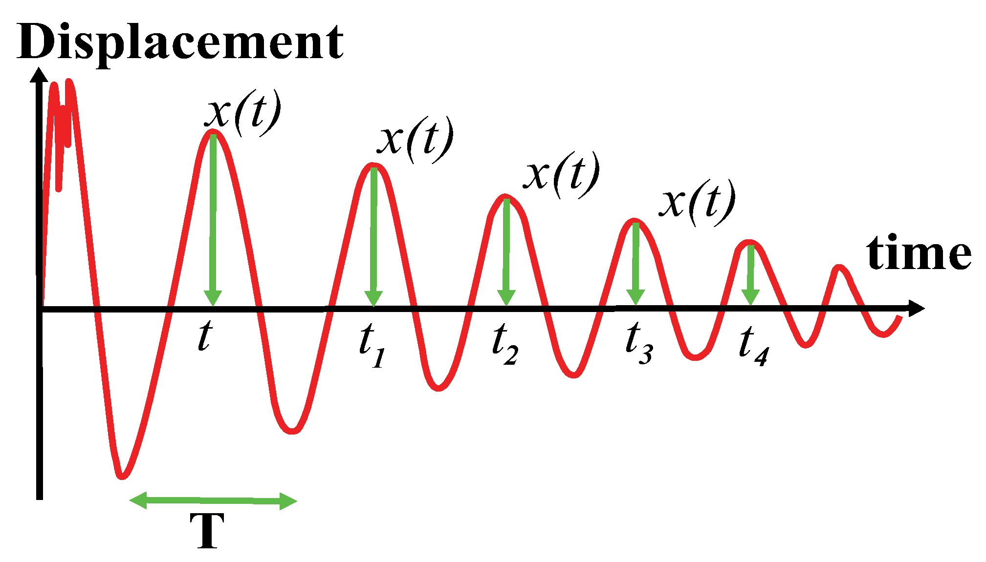
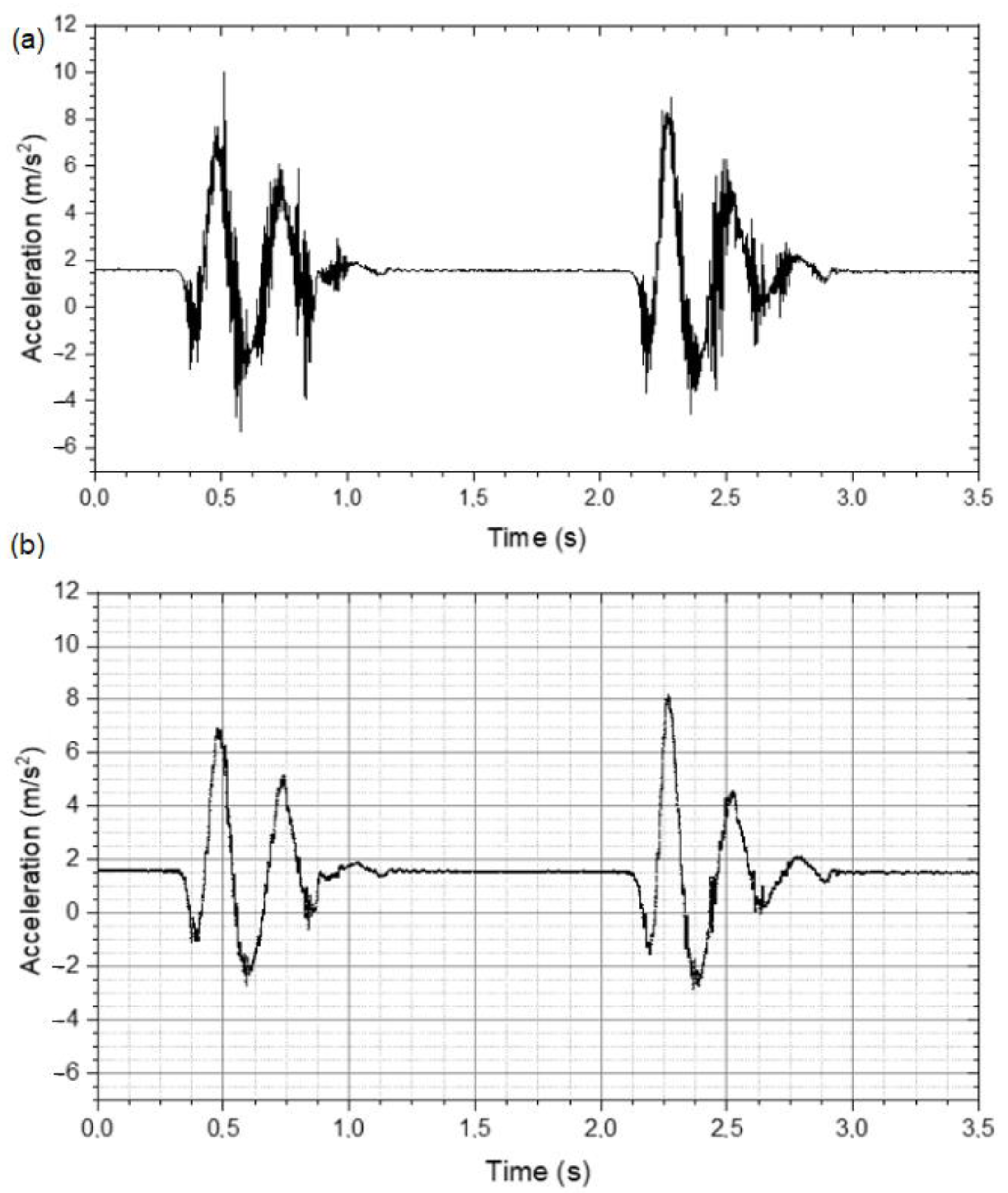
Free vibrations can be used to measure properties of a dynamic system. After applying a certain impulse excitation, by using a hammer or manually, natural frequency mode was activated. Then, by means of the accelerometer, we can determine the displacement, by integrating twice, from the point where the structure was excited.
The results are a graph similar to the illustrative graph shown in
Figure 12. From this measurement, two important quantities are derived. The first important element is the period of oscillation, which is the time between two peaks. As the signal is supposed to be periodic, it is often best to estimate
T as:
where
is the time at which the nth peak occurs, as shown in
Figure 12. Secondly, logarithmic decrement. This can be defined as follows:
where
is a displacement located at the nth peak. In principle, by selecting any two close peaks, and calculating
δ, we can get the same answer, whichever peaks you choose. However, it is often more precise to obtain
using the next formula:
From
T and
δ, we can deduce
and
as follows:
From Equation (6) definitions, we can thus obtain stiffness k and damping coefficient c.
All the configurations (with 2, 3, and 4 magnets) were mounted and tested in order to characterize dynamically their behavior.
5. Conclusions
It can be worthwhile to explore more exotic solutions in order to provide mechanical components with elastic response and damping capacity, but at the same time clean and reliable for space mechanisms applications. In this work, we propose to integrate a passive magnetic spring and an eddy current damper into a single device. The key point is to get the benefit of the moving magnets used in the magnetic spring to couple their magnetic field with a conductive element to provide damping capacity. This way, the device can be compact, lighter, and suitable for space applications.
Three configurations with 2, 3, and 4 magnets axially distributed and in opposite polarizations were designed, simulated, manufactured, and tested. A stiffness of 2410, 2050, 2090 N/m and damping coefficient of 5.45, 10.52 and 17.25 Ns/m was measured for the 2-, 3- and 4-magnets configurations, respectively. This type of suspension demonstrates a specific stiffness performance of the same order of magnitude as those of mechanical conventional suspensions. On the other hand, specific measured damping is an order of magnitude lower. In any case, this magnetic suspension provides good mechanical behavior combined with cleanness and reliability, which are properties highly sought after in mechanical engineering for space developments.

 ,
, 


