
Piezoelectric MEMS Linear Motor for Nanopositioning Applications
by
 , , and
Víctor Ruiz-Díez
1,* ,
,
Jorge Hernando-García
1,
Javier Toledo
1,
Abdallah Ababneh
2,
Helmut Seidel
3 and
José Luis Sánchez-Rojas
1 1
Microsystems, Actuators and Sensors Group, Universidad de Castilla-La Mancha, E-13071 Ciudad Real, Spain
2
Electronic Engineering Department, Hijjawi Faculty for Engineering Technology, Yarmouk University, Irbid 21163, Jordan
3
Chair of Micromechanics, Microfluidics/Microactuators, Faculty of Natural Sciences and Technology, Saarland University, 66123 Saarbrücken, Germany
*
Author to whom correspondence should be addressed.
Actuators 2021, 10(2), 36; https://0-doi-org.brum.beds.ac.uk/10.3390/act10020036
Submission received: 1 February 2021
/
Revised: 15 February 2021
/
Accepted: 16 February 2021
/
Published: 18 February 2021
(This article belongs to the Special Issue Selected Papers from the 1st International Electronic Conference on Actuator Technology: Materials, Devices and Applications (IeCAT))
Abstract
:This paper reports the design, fabrication, and performance of piezoelectric bidirectional conveyors based on microelectromechanical systems (MEMS) and featuring 3D-printed legs in bridge resonators. The structures consisted of aluminum-nitride (AlN) piezoelectric film on top of millimeter-sized rectangular thin silicon bridges and two electrode patches. The position and size of the patches were analytically optimized for travelling or standing wave generation, while the addition of 3D-printed legs allowed for a controlled contact and amplified displacement, a further step into the manufacturing of efficient linear motors. Such hybrid devices have recently demonstrated the conveyance of sliders of several times the motor weight, with speeds of 1.7 mm/s by travelling waves generated at 6 V and 19.3 kHz. In this paper both travelling and standing wave motors are compared. By the optimization of various aspects of the device such as the vibrational modes, leg collocation and excitation signals, speeds as high as 35 mm/s, and payloads above 10 times the motor weight were demonstrated. The devices exhibited a promising positional resolution while actuated with only a few sinusoidal cycles in an open-loop configuration. Discrete steps as low as 70 nm were measured in the conveyance of 2-mg sliders.
1. Introduction
The miniaturization of actuators is an ongoing challenge, especially for applications that need large displacements, high energy efficiency, or output forces [1]. In search of high efficiency, torque and power to weight ratio, long motion range, and quick response, piezoelectric ultrasonic motors (USMs) have proven to be a suitable solution in comparison to electrostatic, magnetic, and thermal alternatives [2,3,4]. Notwithstanding the advantages of USM for linear motion, the difficulties in generating standing or travelling waves at high frequencies with enough amplitude make the scaling down of these motors to the millimeter range a challenge [5].
The monolithic fabrication based on silicon micromachining was successfully applied to the effective size reduction of such positional devices. The microelectromechanical systems (MEMS) technology has helped different actuation techniques in demonstrating locomotion or conveyance in the millimeter scale with speeds of a few millimeters per second and payloads below 50 mg [6,7,8]. However, in order to take a step further into the miniaturization of efficient motors, piezoelectric actuation becomes a promising alternative. Piezoelectric transducers have proven to be a suitable solution for the miniaturization of actuators either working as resonators, where a high frequency resolution and low damping is sought [9], micromanipulation [10], or ultrasonic motors [1]. In this regard, TW-based bidirectional motors in the millimeter scale have demonstrated rotational speeds above 1500 rpm using thin-film PZT on silicon rotors with teeth, by combining two degenerate orthogonal modes [11] and linear speeds as high as 1.7 mm/s using thin-film AlN on silicon with 3D printed resin legs and two flexural modes [12]. The combination of two orthogonal bending modes in a 10 × 10 mm2 Mn-BSPT square plate recently demonstrated linear speeds of 200 mm/s with payloads above 35 g [13]. However, attaining high linear speeds and high payloads, together with accurate and precise positioning is a challenge of recent interest in piezoelectrically actuated microrobots [14]. Tellers et al. [15] proposed a linear conveyor based on an array of PZT-actuated microhammers, capable of transporting 2 mg masses at 1 mm/s with 5 V excitation and positional errors as low as 80 µm, without speed control.
In this work, a hybrid design for linear locomotion based on piezoelectric MEMS resonators with attached 3D-printed legs is presented. The MEMS-based resonator consists of a conductive silicon bridge, actuated due to an integrated aluminum-nitride (AlN) piezoelectric film sandwiched between the silicon film and the metallic electrodes. The optimal electrode layout for the efficient generation of the mechanical waves, i.e., standing wave or travelling wave, in the motor was calculated using analytical models. An array of 3D-printed legs attached to the motor surface transferred the movement of the surface of the silicon plate to a slider. These legs allowed a controlled contact between the stator and slider, and the amplification of the elliptical or the diagonal movement caused by the travelling wave (TW) or the standing wave (SW), respectively. The kinetic capabilities of the motors were characterized under both operation modes with the conveyance of sliders with different masses.
2. Materials and Methods
2.1. Device Design
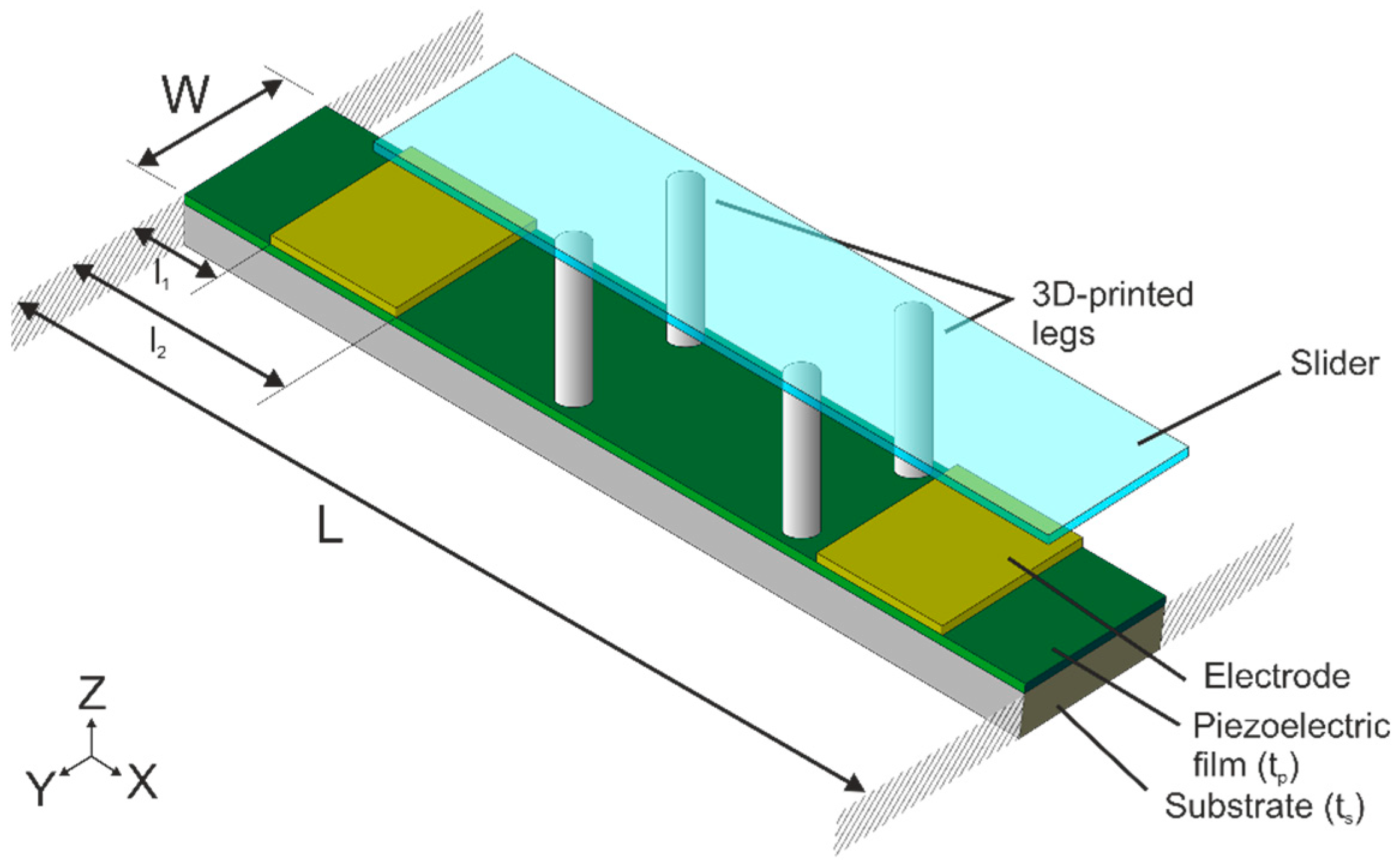
In this work, we focused on linear motors based on piezoelectrically actuated bridges with a length and a width . The device layout is as follows: a 30 µm thick p-doped (100) silicon plate serves as bottom electrode, which is covered with a 1 µm thick aluminum-nitride (AlN) piezoelectric film. As top electrode, two 500 nm thick gold (Au) patches were deposited on top. These patches were neglected in the mechanical analysis. Figure 1 depicts the layout.
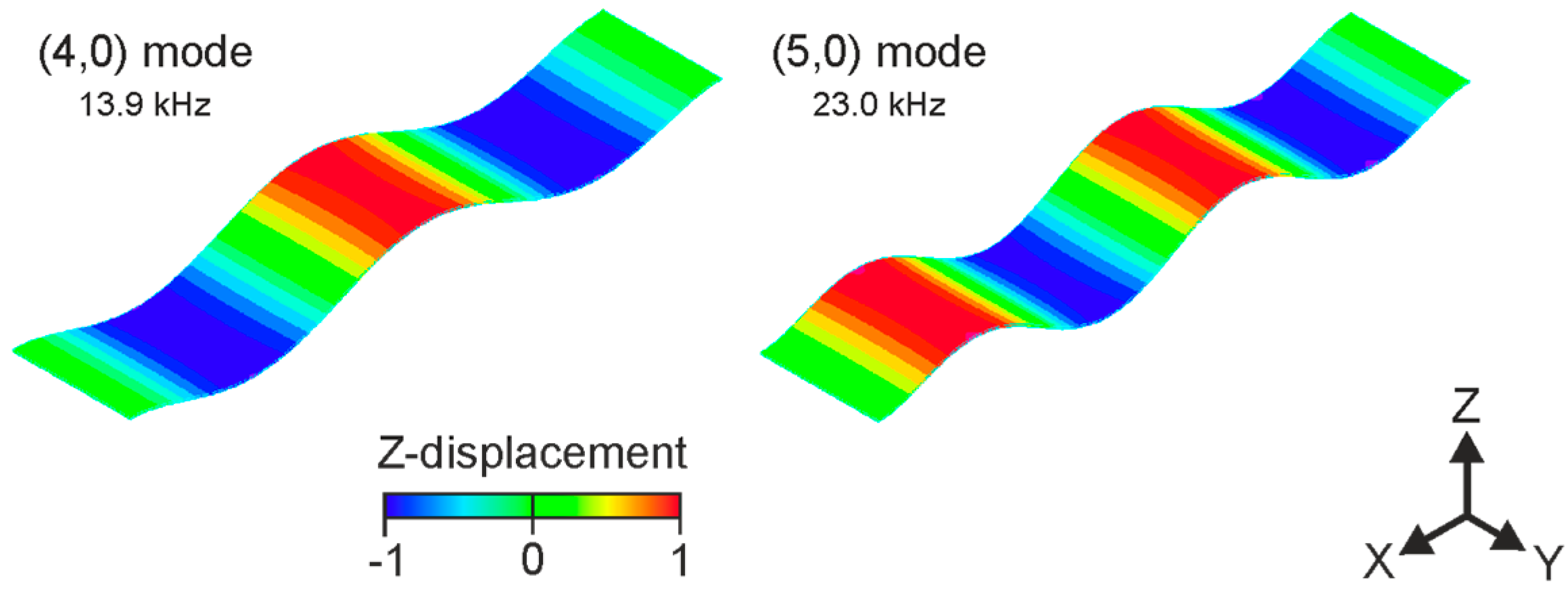
The generation of bidirectional linear motion is based on the flexural vibration modes of the bridge structure in Figure 1. These modes were named using two indexes, first designating the number of nodal lines along the beam, and second those orthogonal to it [16]. Figure 2 shows the mode shapes for third and fourth order bending modes, i.e., (4,0) and (5,0) modes using this convention. Their corresponding resonant frequencies are also given. Both were calculated by a FEM analysis using the commercial software ADINA [17].
The generation of mechanical waves—either standing wave (SW) or travelling wave (TW) types—on the piezoelectrically actuated structure, together with the inclusion of 3D-printed millimeter-long legs comprises the actuation principle of the motor. The contact between the vibrating structure and the rotor will be assured by the attached legs, which would transmit a translational motion to the slider. Although the generation of TW was also possible with higher order modes and despite the potentially higher speeds associated with higher frequencies, practical locomotion was not attained [12]. The required amplitude of the modes utilized in a SW or TW-actuated conveyor is met in the low frequency range, being the (4,0) and (5,0) modes a well-balanced pair, in the middle of the range. In the following sections, the design of TW-based and SW-based motors will be described.
2.1.1. Travelling-Wave Based Linear Motion
The generation of linear TW in rectangular plates by the combination of two flexural modes of vibration was already reported, using two symmetrically disposed piezoelectric patches on silicon micromachined AlN-actuated cantilevers [18] and centimeter sized PZT-actuated motors [19,20,21]. Here we followed the same analytical approach applied to two consecutive flexural modes, i.e., (4,0) and (5,0) modes (see Figure 2) with an effective size reduction to the millimeter scale by a silicon micromachined AlN-actuated bridge. The patch position and size were determined to optimize the TW generation and vibration amplitude in the device [12]. The driving frequency was fixed to the intermediate frequency between the resonant frequencies of the two flexural modes, with a permanent phase difference of 90° between the sinusoidal signals applied to the electrode patches. The optimization was carried out by selecting those patches that maximize the average amplitude of the TW (<TW>) while ensuring an acceptable quality of the same–quantified through the standing-wave-ratio (SWR) or the ratio of the maximum to the minimum value of the envelope [12].
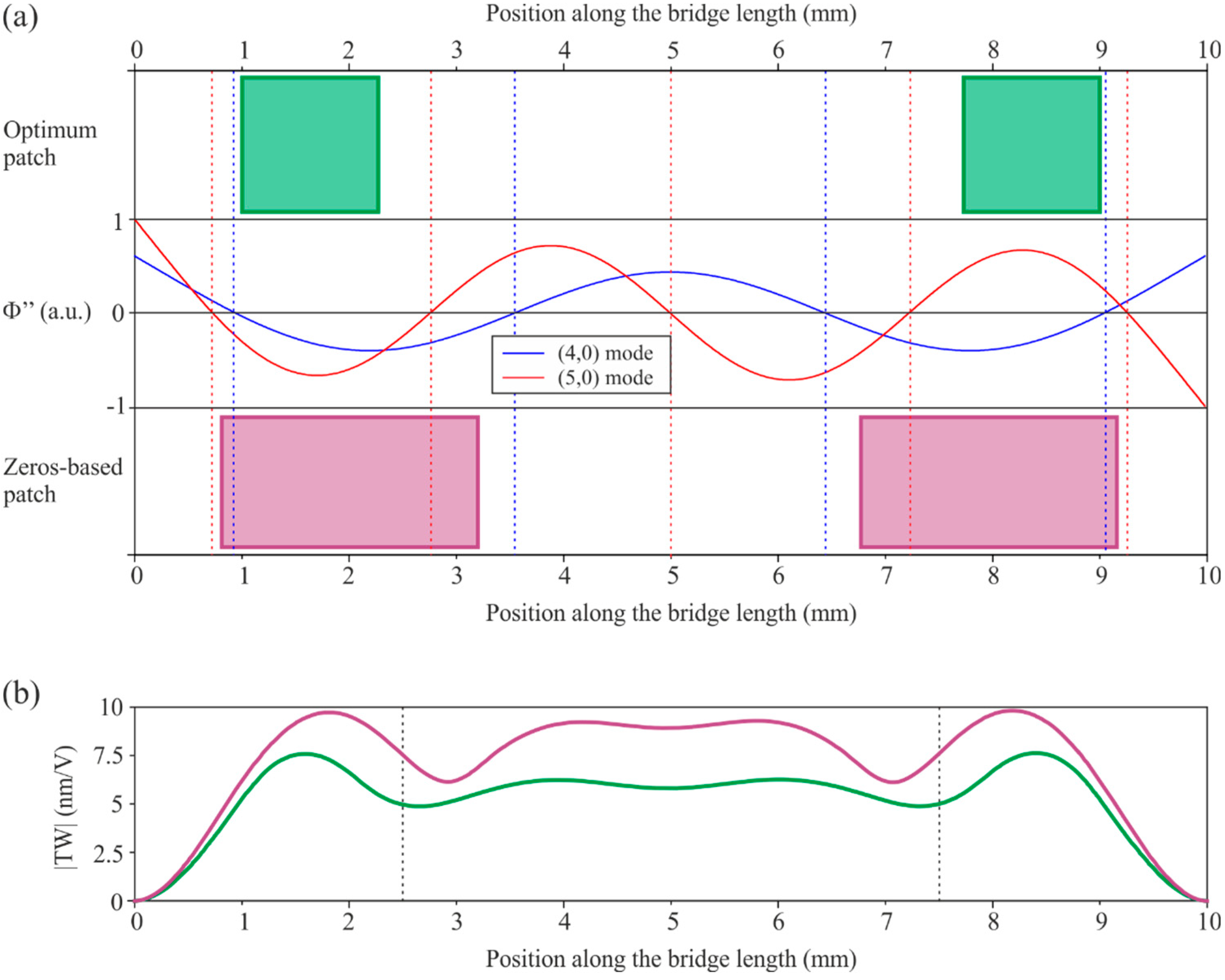
Figure 3a shows the deduced optimal patches (green areas) for a maximum SWR of 1.4 and Figure 3b shows the calculated envelope of the TW for those patches, with an estimated <TW> of 5.7 nm/V and a SWR of 1.3. As it can be seen in Figure 3a, these optimal patches partially cover the region between the zeros of the second derivatives of the modal shapes of the modes involved. The charge collected by a piezoelectric film in a composite beam is proportional to the integral of the second derivative of the out-of-plane deformation, which is proportional to the modal shape, in the region covered by the metallic electrode [22,23,24]. Dotted vertical lines in Figure 3a determine the change in the sign of these second derivatives, which in turn are related to changes in the sign of stress and charge. A patch fully covering this region (purple area in Figure 3a) could optimally excite both vibration modes at each particular resonant frequency maximizing the <TW>, without accounting for the SWR, as it was recently demonstrated [12]. As it can be seen in Figure 3b, the zeros-based patches showed a <TW> of 8.1 nm/V and a SWR of 1.5, which could lead to TWs of acceptable quality.
Once the design for TW generation was achieved, our next step was to ensure the contact of the vibrating structure with the slider to be transported. This is a significant improvement with respect to ref. 16, in which a TW was also generated in a comparable silicon micromachined AlN-actuated structure, but practical locomotion was not demonstrated. Our approach consisted of the inclusion of legs on the motor surface. According to reference [20] in order to attain an elliptical trajectory at the tip of the legs, the TW envelope should be ideally constant. That condition is met at the central plateau of the TW envelope, as it can be seen in Figure 3b [12].
2.1.2. Standing-Wave Based Linear Motion
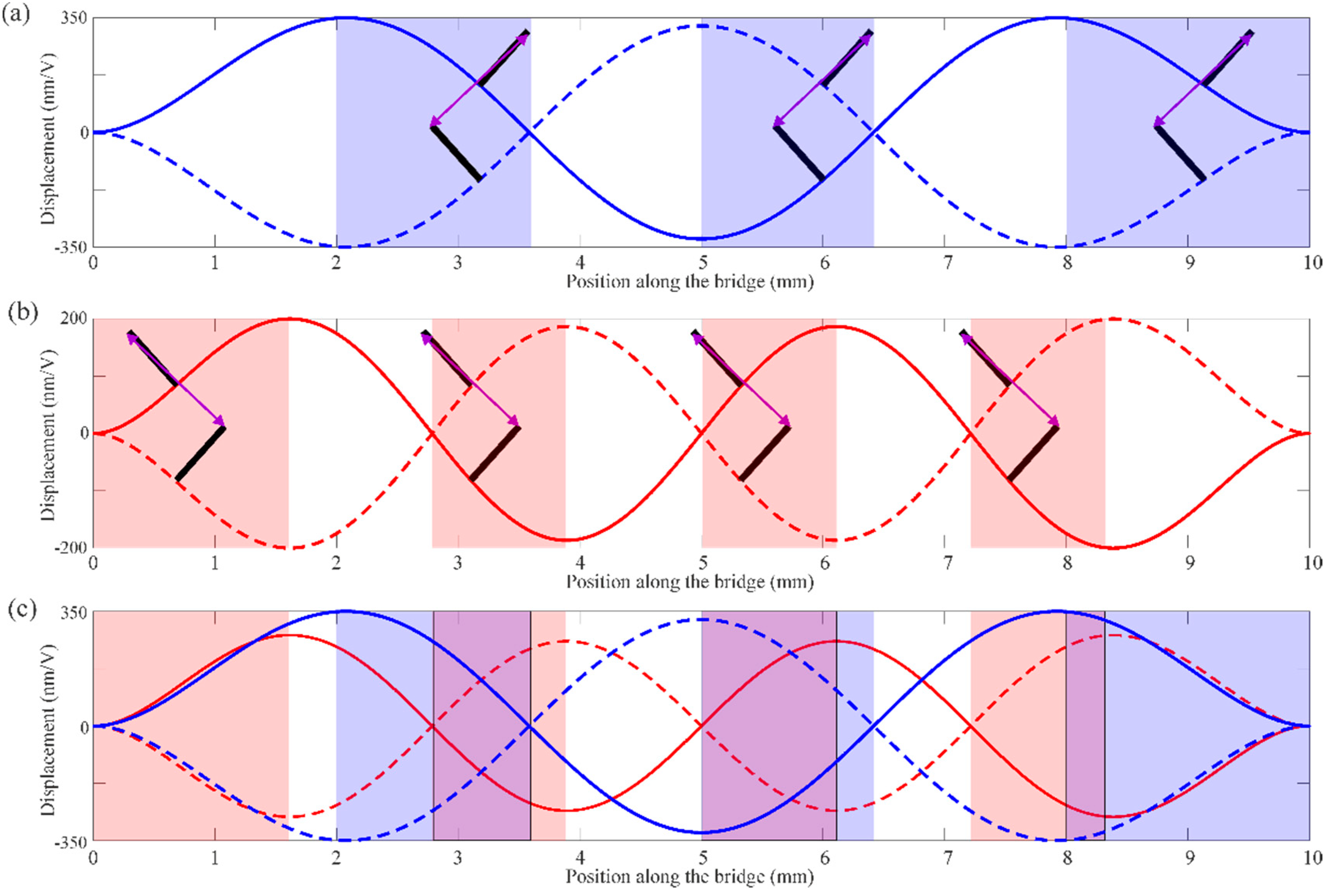
Linear motion can also be obtained by inducing an SW in the resonator, based on flexural modes, by an appropriate distribution of legs [25]. Figure 4a,b shows the calculated maximum and minimum deformation of the plates for standing waves of the (4,0) and (5,0) modes obtained by the beam model approximation [12]. As depicted, a leg placed between a node and a peak of the wave would describe a rectilinear trajectory, assuming it is stiff enough to follow the surface deformation. The thrust exerted to the rotor would be in the positive or negative direction along the wave depending on the chosen side of the crest. Therefore, to achieve bidirectional motion, two distinct flexural modes were used, i.e., the (4,0) mode and the (5,0) mode, while choosing different sides of the crest for each one. In Figure 4a, the legs on the right side of the crest would push the slider towards the right, while in Figure 4b, the legs on the left side of the crest would push the slider towards the left direction. As a consequence, the same device could be used as an SW motor, with two different directions of movement depending on the resonance frequency excited, by placing the legs at any of the intersecting regions in Figure 4c.
Since the device should be excited in either of the two consecutive flexural modes, the position and size of the electrode patches should be optimized to equally excite both. According to reference [12], this patch should cover the region among the midpoints between the zeros of the second derivatives of the targeted modes. We have referred to this region as the zeros-based patch, the purple area in Figure 3a. In addition, the optimum patch chosen for the TW generation—the green area in Figure 3a—that belongs to this region, may be suitable for the SW generation and allowed us to compare the same physical device in both operation modes, TW or SW, just by changing frequencies and phases of the applied signals.
Lastly, the excitation of the flexural modes could be maximized by taking advantage of the two-patch configuration excited at a given modal frequency, by the appropriate selection of the phase difference [22]. As it can be seen in Figure 3a, the optimum patches cover regions of the same sign of the second derivative of the (4,0) mode, so no phase difference should be applied between patches while exciting at the (4,0) mode resonant frequency. On the contrary, the optimum patches cover regions with opposite sign of the second derivative of the (5,0) mode, so a 180° phase difference between both patches would maximize the actuation of the (5,0) mode.
A summary of the design considerations for both the TW and SW-driven motor can be found in Table 1. In order to have the same device working in either of the two operation modes, the optimum patch from the TW was chosen (Figure 3a), while the leg position was restricted by the first region from the SW design considerations (Figure 4c). This is indicated in Table 1 in bold type. The driving frequencies and phase differences for both operation modes and moving directions are also summarized in Table 1.
2.2. Device Fabrication
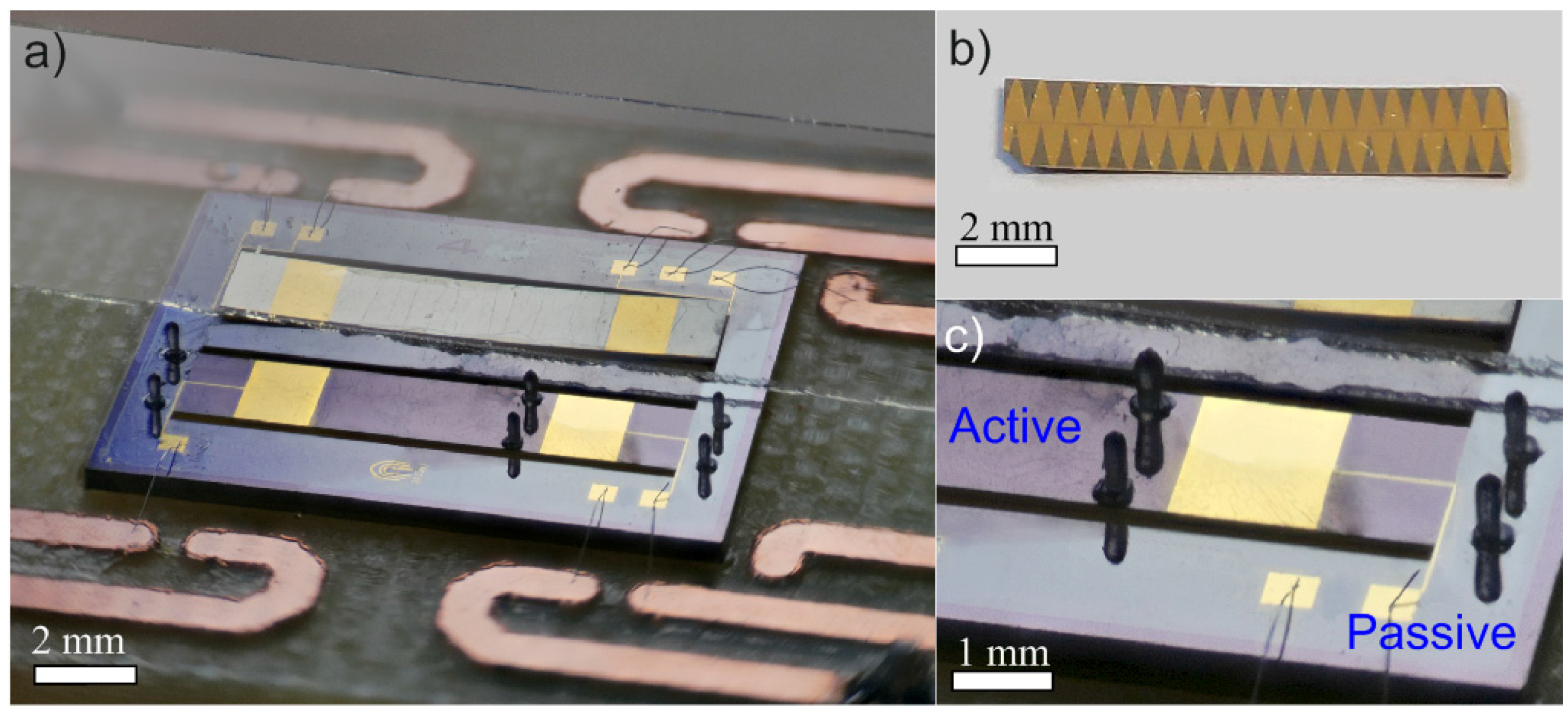
In order to implement rectangular micro bridges according to the geometry and materials previously described, monolithic microfabrication techniques were used. The fabrication of the devices followed this process: a 30-μm thick, p-doped (100) silicon plate served as the bottom electrode, which was covered with a 1-μm thick AlN piezoelectric film synthesized in a reactive sputter process from an aluminum target in a pure nitrogen atmosphere. As the top electrode, 500-nm thick Au electrodes were deposited. Dices containing two different devices were glued and wire-bonded to a printed circuit board (PCB) to facilitate electrical access (Figure 5).
The movement of the surface of the silicon plate was transferred to a slider through an array of 3D-printed legs. These legs consisted of cylindrical pillars with a length of 750 µm and a diameter of 300 µm, that were manufactured by a B9 Core 530 DLP 3D printer, using proprietary black resin (density of , Young’s modulus of ). A cyanoacrylate-based adhesive was used to glue three pairs of legs on the device surface: an active pair of legs on the bridge surface, and two additional pairs at the device frame, serving as passive supports (see Figure 5). The position of the active pair was determined by the previous design considerations (Table 1), so the same device could be operated as a TW and SW-driven motor. The fabricated devices were optically and electrically characterized before and after leg attachment, and no substantial variation in the motor characteristics was observed.
2.3. Characterization Methods
Due to the integrated piezoelectric layer, an all-electrical actuation/detection scheme was possible and hence, the electrical performance of the AlN-actuated devices could be studied by recording the impedance spectrum of the different modes of vibration. A 4294A Agilent impedance analyzer was used for this purpose. For the optical characterization of both modes of vibration and the generated TW and SW, a scanning laser Doppler vibrometer (Polytec MSV 400) was employed. The TW was generated by applying sinusoidal excitations on both electrode patches, with a driving frequency corresponding to the intermediate frequency between those measured for the two modes involved and a phase difference of , while recording the out-of-plane displacement of the entire device surface. As in the device design section, the figures of merit of the TW generation were calculated in a window located at the center of the device, covering 50% of the length. The standing waves were generated by applying sinusoidal excitations on both electrode patches, with a phase difference of 0 for the (4,0) mode and 180 for the (5,0) mode.
In the kinetic characterization, the required waveforms were applied to each of the electrode patches using a Tektronix AFG 3000 series arbitrary waveform generator (AWG). In the experimental setup, the PCB containing a pair of such devices (see Figure 5) was placed on a leveled platform to avoid an uneven movement of the slider under the microscope camera. A pair of thin glass pieces restricted the horizontal movement of the slider to a rectilinear lane. In order to obtain the slider positions versus time, the movement of the slider was optically recorded by a microscope camera, and the videos were processed by a motion tracking algorithm programmed in MATLAB. The mean speed was computed afterward.
3. Results
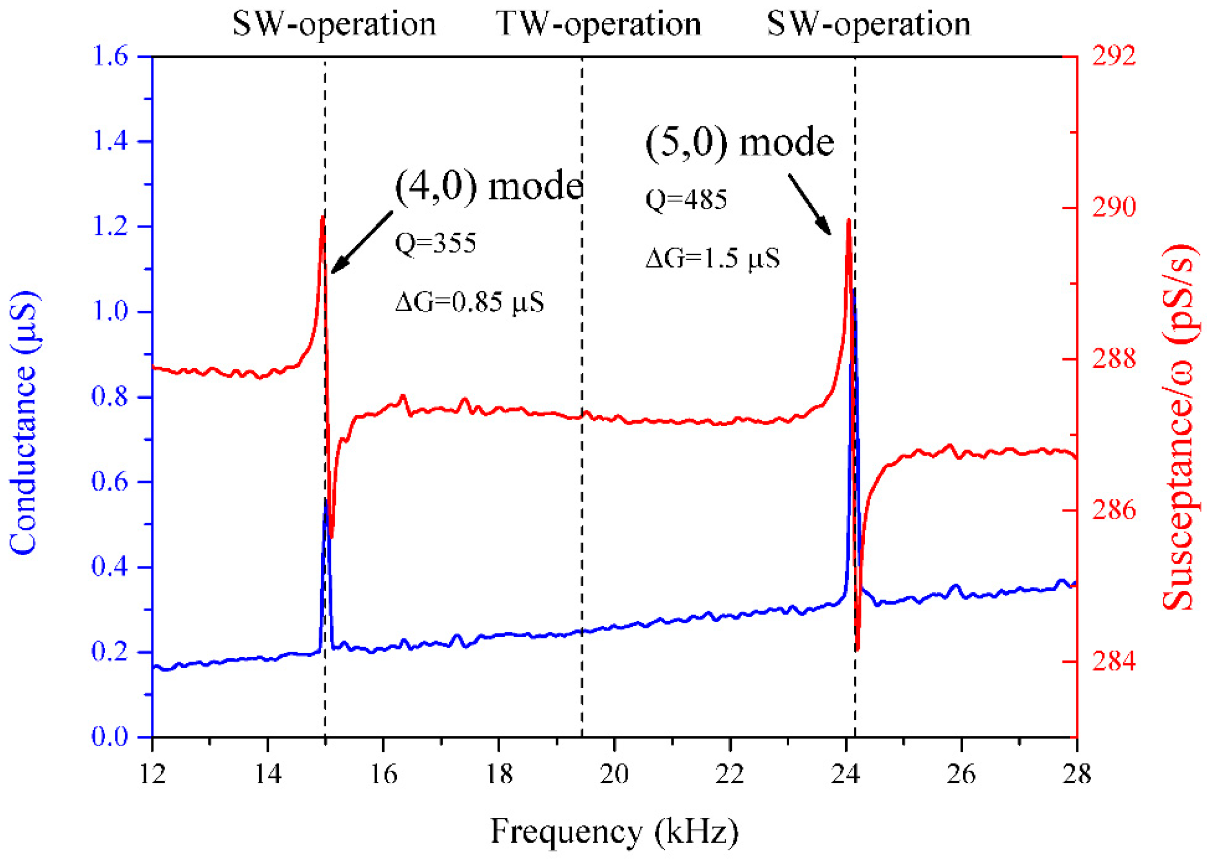
Figure 6 shows the real and imaginary parts of the measured admittance spectra of the fabricated device. Peaks corresponded to the vibration modes of interest. The modal identification by laser Doppler vibrometer is also indicated. It is also worth pointing out the absence of significant peaks in between the targeted modes, i.e., (4,0) and (5,0) mode, together with the high Q-factor (355 and 485, respectively) and motional conductance (0.85 µS and 1.5 µS), which positively contribute to the TW and SW generation. As it can be seen, the resonant frequencies for the (4,0) and (5,0) modes in the fabricated device were 15.25 and 24 kHz, respectively. This implies a difference of less than 10% with respect to the simulated values from the design section, which can be attributed to fabrication tolerances.
The optical characterization of the motor was performed by applying sinusoidal excitations as described in the previous section. The measured TW, excited at 19.55 kHz, showed a SWR value as low as 1.6 and an amplitude <TW> of 4.76 nm/V in the central plateau with a linear evolution of the phase along the bridge length, as expected. The SWs showed amplitudes of vibration of 320 nm/V and 240 nm/V for the (4,0) and (5,0) modes, respectively.
The application of the motor to transport objects in contact with the legs was assessed in the two operation modes, with sliders consisting of silicon plates with a top area of 15 × 3 mm2 and different thicknesses, so the mass of the slider was in the range from 2 to 21 mg, i.e., from one to ten times the mass of the motor. In the TW operation mode, the motor was actuated at 19.55 kHz with a phase difference of 90° for the forward direction and −90° for the reverse direction. In the SW operation mode, the motor was actuated in the (5,0) mode at 24 kHz with a phase difference of 180° for the forward direction and in the (4,0) mode at 15.25 kHz with no phase difference between patches for the reverse direction.
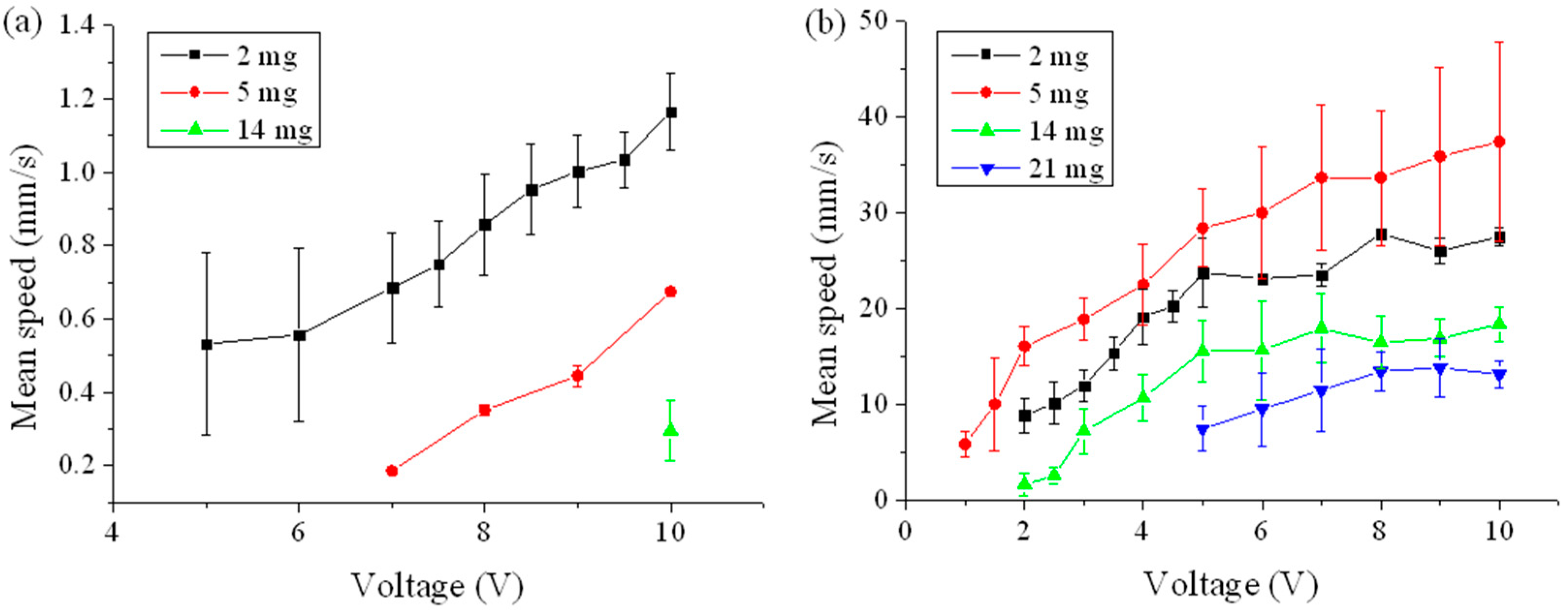
Figure 7 shows the results from the kinetic characterization in the forward direction (similar results were obtained in the reverse direction) for the two operation modes, different sliders, and applied voltages. The speed value and error bars were calculated from the mean and standard deviation of the slider speed in 30 consecutive experiments. Comparing both operation modes with the lightest slider, the maximum conveyor speed was 1.2 mm/s in the TW operation mode and 27 mm/s in the SW operation mode. This speed of almost 3 BL/s (body-lengths per second) implies a remarkable improvement compared to the TW operation mode, mainly due to the actuation of the motor in resonance.
In the TW operation mode (Figure 7a), a linear dependence of the speed with the applied voltage was found while an increase in the slider mass reduced the conveyor speed. The maximum payload in this operation mode was 14 mg, where a conveyor speed of 0.3 mm/s was measured with 10 V excitation. The minimum excitation in this operation mode was 3 V with the 2 mg-slider, although these limit conditions showed errors in speed of 50%. On the other side, in the SW operation mode (Figure 7b), an increase in the slider mass from 2 to 5 mg, increased the conveyor speed. A maximum speed of 35 mm/s was measured with this 5 mg-slider at 10 V. This might be related to an increase in the ratio of the frictional force to the slider inertia as increasing the payload above 5 mg, the conveyor speed was reduced. It is also notorious that greater deviations in the mean speed measurements were shown with this slider, which might be attributed to slight differences in the contact and friction forces related to a heavier mass moving at higher speeds, when compared to the other sliders. The maximum payload in this operation mode was 21 mg, roughly 10 times the motor weight and the minimum excitation was as low as 1 V with the 5 mg-slider.
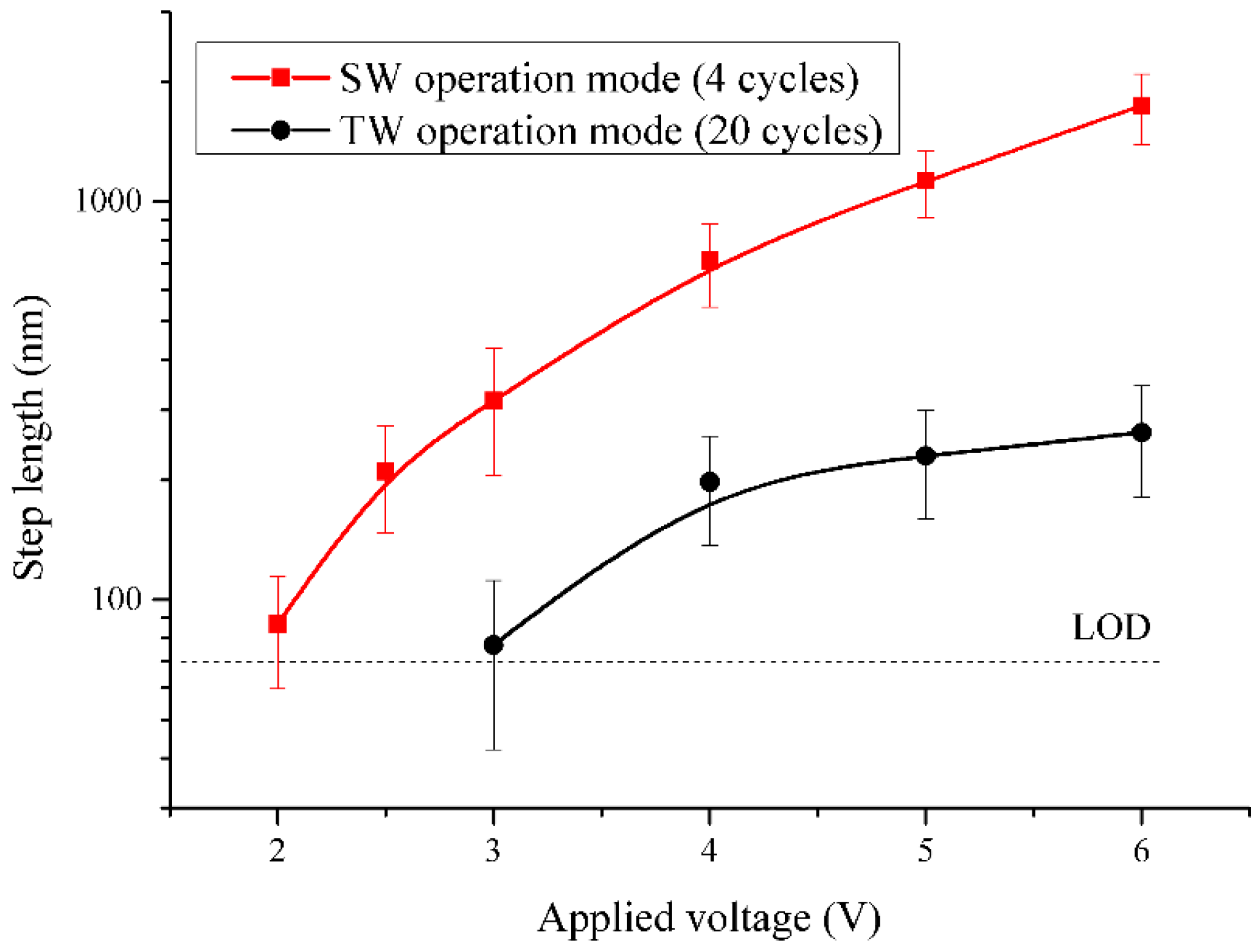
The potential of the fabricated motors to move objects with nanometer resolution was also investigated. Figure 8 shows the experimental results from the minimum displacement study in both operation modes with the 2 mg slider. The same experimental setup as for the kinetic characterization was used, but with the slider moved in discrete steps. In these experiments, the positioning resolution of the slider was studied in an open loop, without any control strategy apart from the driving signal. Only a few cycles of the corresponding excitation signals were applied to the patches, searching for the minimal actuation that generated a mechanical wave able to move the slider between two distinguishable positions. For an applied voltage amplitude of 5 V, the minimum number of periods of the sinusoidal voltage required to generate a repeatable stepped motion of the slider was found to be 20 in the TW operation mode and 4 cycles in the SW case. A larger number of excitation cycles increased the step length, so 20 and 4 were chosen as the minimum number of excitation cycles for these particular devices. This was accomplished with 20 or 4 cycles in the TW or SW cases, respectively. Then, the applied voltage was swept in the range from 0 to 6 V.
As can be seen, both operation modes were able to reach a minimum step value of 70 nm. This distance was close to the technical limit of the measurement setup, but even a lower minimum step could be reached by reducing the applied voltage further. The SW operation mode demonstrated better performance, being able to reach the same minimum step as the TW counterpart with five times fewer cycles and less voltage. As a reference for comparison, SAW linear actuators have demonstrated frictional driven steps as low as 2 nm with 20 cycles excitation while requiring high preloads and actuation voltages, which translates into higher wear rates and power consumption [26]. In addition, typical MEMS-based nanopositioners perform with dynamic ranges (DR = resolution/range) below 104 [27,28]. In our case, with a positional resolution of 70 nm and typical motion ranges of 3 mm, a DR = 4.5 × 10⁴ was demonstrated. This supposes a great improvement for piezoelectrically actuated MEMS positioners, and it confirms the potential of our proposed design for nanopositioning applications, where control over force, trajectory, and other variables will have to be implemented.
4. Conclusions
This work reports the design, fabrication, and electrical and optical characterization of piezoelectric MEMS plates for linear motion applications with nanometer resolution. The generation of bidirectional TW was successfully demonstrated on a monolithic microfabricated silicon-based bridge with 3D-printed legs. These legs helped to overcome the intrinsic limitation of the suspended bridge to attain efficient contact with objects. In addition, the motors were also actuated in resonance, inducing a SW based on the (4,0) and (5,0) flexural modes. The 3D-printed legs were placed at those positions in which the resonator could act as a bidirectional resonant motor.
The speed characteristics of the fabricated device was studied with sliders of different mass. The linear motor demonstrated maximum bidirectional speeds of 1.2 mm/s when a TW was induced in the resonator at 10 V and a frequency of 19.55 kHz with the 2 mg slider. The operation in resonance was possible by inducing SWs based on the (4,0) and (5,0) modes at 15.25 and 24 kHz. Speeds as high as 35 mm/s for continuous sinusoidal excitation with a 5 mg were demonstrated in this operation mode. With the maximum payload, a 21 mg slider, the speed was lowered to 10 mm/s.
Besides, using a burst sinusoidal excitation comprising 20 cycles, the TW generated in the bridge surface was able to move the 2 mg slider in discrete steps of 70 nm, in both directions. In the SW operation mode, the burst excitation could be lowered to only 4 cycles, obtaining the same minimum step for much lower energy input.
Author Contributions
Conceptualization, J.L.S.-R.; software, V.R.-D.; investigation, V.R.-D.; writing—original draft preparation, V.R.-D.; writing—review and editing, J.L.S.-R., J.H.-G., J.T., H.S. and A.A.; supervision, J.L.S.-R. and J.H.-G.; project administration, J.L.S.-R. and J.H.-G.; funding acquisition, J.L.S.-R. and J.H.-G. All authors have read and agreed to the published version of the manuscript.
Funding
This work was supported by the European Regional Development Fund, the Spanish Ministerio de Ciencia, Innovación y Tecnología project (RTI2018-094960-B-100), the regional government (JCCLM) project (SBPLY/17/180501/000139) and the German Research Council (DFG) (SE 1425/14-1).
Conflicts of Interest
The authors declare no conflict of interest.
References
- Uchino, K. MicroMechatronics, 2nd ed.; CRC Press: Boca Raton, FL, USA, 2019. [Google Scholar]
- Chan, M.L.; Yoxall, B.; Park, H.; Kang, Z.; Izyumin, I.; Chou, J.; Megens, M.M.; Wu, M.C.; Boser, B.E.; Horsley, D.A. Design and Characterization of MEMS Micromotor Supported on Low Friction Liquid Bearing. Sens. Actuators Phys. 2012, 177, 1–9. [Google Scholar] [CrossRef]
- Khiat, A.; Spronck, J.W.; van Schieveen, J.; Milosavljevic, S.; Wei, J.; Estevez, P.; Sarro, P.M.; Staufer, U. Linear and Rotational Thermal Micro-Stepper Motors. Microelectron. Eng. 2012, 98, 497–501. [Google Scholar] [CrossRef]
- Sarajlic, E.; Yamahata, C.; Cordero, M.; Fujita, H. Three-Phase Electrostatic Rotary Stepper Micromotor With a Flexural Pivot Bearing. J. Microelectromech. Syst. 2010, 19, 338–349. [Google Scholar] [CrossRef]
- Pulskamp, J.S.; Polcawich, R.G.; Rudy, R.Q.; Bedair, S.S.; Proie, R.M.; Ivanov, T.; Smith, G.L. Piezoelectric PZT MEMS Technologies for Small-Scale Robotics and RF Applications. MRS Bull. 2012, 37, 1062–1070. [Google Scholar] [CrossRef]
- Kladitis, P.E.; Bright, V.M. Prototype Microrobots for Micro-Positioning and Micro-Unmanned Vehicles. Sens. Actuators Phys. 2000, 80, 132–137. [Google Scholar] [CrossRef]
- Ebefors, T.; Mattsson, J.U.; Kälvesten, E.; Stemme, G. A Walking Silicon Micro-Robot. In Proceedings of the 10th International Conference on Solid-State Sensors and Actuators, Sendai, Japan, 7–10 June 1999; Transducers’99. pp. 1202–1205. [Google Scholar]
- Yahiaoui, R.; Zeggari, R.; Malapert, J.; Manceau, J.-F. A MEMS-Based Pneumatic Micro-Conveyor for Planar Micromanipulation. Mechatronics 2012, 22, 515–521. [Google Scholar] [CrossRef]
- Bhugra, H.; Piazza, G. (Eds.) Piezoelectric MEMS Resonators; Microsystems and Nanosystems; Springer International Publishing: Berlin/Heidelberg, Germany, 2017; ISBN 978-3-319-28686-0. [Google Scholar]
- Belfiore, N.P. Micromanipulation: A Challenge for Actuation. Actuators 2018, 7, 85. [Google Scholar] [CrossRef] [Green Version]
- Smith, G.L.; Rudy, R.Q.; Polcawich, R.G.; DeVoe, D.L. Integrated Thin-Film Piezoelectric Traveling Wave Ultrasonic Motors. Sens. Actuators Phys. 2012, 188, 305–311. [Google Scholar] [CrossRef]
- Ruiz-Díez, V.; Hernando-García, J.; Toledo, J.; Ababneh, A.; Seidel, H.; Sánchez-Rojas, J.L. Bidirectional Linear Motion by Travelling Waves on Legged Piezoelectric Microfabricated Plates. Micromachines 2020, 11, 517. [Google Scholar] [CrossRef]
- Chen, J.; Chen, Z.; Li, X.; Dong, S. A High-Temperature Piezoelectric Linear Actuator Operating in Two Orthogonal First Bending Modes. Appl. Phys. Lett. 2013, 102, 052902. [Google Scholar] [CrossRef]
- Schlinquer, T.; Homayouni-Amlashi, A.; Rakotondrabe, M.; Ousaid, A.M. Design of Piezoelectric Actuators By Optimizing the Electrodes Topology. IEEE Robot. Autom. Lett. 2021, 6, 72–79. [Google Scholar] [CrossRef]
- Tellers, M.C.; Pulskamp, J.S.; Bedair, S.S.; Rudy, R.Q.; Kierzewski, I.M.; Polcawich, R.G.; Bergbreiter, S.E. Characterization of a Piezoelectric MEMS Actuator Surface toward Motion-Enabled Reconfigurable RF Circuits. J. Micromech. Microeng. 2018, 28, 035001. [Google Scholar] [CrossRef]
- Leissa, A.W.; Qatu, M.S. Vibration of Continuous Systems; McGraw Hill Professional: New York, NY, USA, 2011; ISBN 9780071714808. [Google Scholar]
- Adina R&D Inc. Automatic Dynamic Incremental Nonlinear Analysis (ADINA). Available online: www.adina.com (accessed on 17 February 2021).
- Díaz-Molina, A.; Ruiz-Díez, V.; Hernando-García, J.; Ababneh, A.; Seidel, H.; Sánchez-Rojas, J.L. Generation of Linear Traveling Waves in Piezoelectric Plates in Air and Liquid. Micromachines 2019, 10, 283. [Google Scholar] [CrossRef] [PubMed] [Green Version]
- Hariri, H.; Bernard, Y.; Razek, A. A Traveling Wave Piezoelectric Beam Robot. Smart Mater. Struct. 2014, 23, 025013. [Google Scholar] [CrossRef]
- Hernando-García, J.; García-Caraballo, J.L.; Ruiz-Díez, V.; Sánchez-Rojas, J.L. Motion of a Legged Bidirectional Miniature Piezoelectric Robot Based on Traveling Wave Generation. Micromachines 2020, 11, 321. [Google Scholar] [CrossRef] [Green Version]
- Malladi, V.V.N.S.; Avirovik, D.; Priya, S.; Tarazaga, P. Characterization and Representation of Mechanical Waves Generated in Piezo-Electric Augmented Beams. Smart Mater. Struct. 2015, 24, 105026. [Google Scholar] [CrossRef]
- Ruiz-Díez, V.; Manzaneque, T.; Hernando-García, J.; Ababneh, A.; Kucera, M.; Schmid, U.; Seidel, H.; Sánchez-Rojas, J.L. Design and Characterization of AlN-Based in-Plane Microplate Resonators. J. Micromech. Microeng. 2013, 23, 074003. [Google Scholar] [CrossRef]
- Lee, C.-K.; Moon, F.C. Modal Sensors/Actuators. J. Appl. Mech. 1990, 57, 434–441. [Google Scholar] [CrossRef]
- Avirovik, D.; Malladi, V.V.N.S.; Priya, S.; Tarazaga, P.A. Theoretical and Experimental Correlation of Mechanical Wave Formation on Beams. J. Intell. Mater. Syst. Struct. 2016, 27, 1939–1948. [Google Scholar] [CrossRef]
- He, S.; Chen, W.; Tao, X.; Chen, Z. Standing Wave Bi-Directional Linearly Moving Ultrasonic Motor. IEEE Trans. Ultrason. Ferroelectr. Freq. Control. 1998, 45, 1133–1139. [Google Scholar] [CrossRef] [PubMed]
- Shigematsu, T.; Kurosawa, M.K.; Asai, K. Nanometer Stepping Drives of Surface Acoustic Wave Motor. IEEE Trans. Ultrason. Ferroelectr. Freq. Control. 2003, 50, 376–385. [Google Scholar] [CrossRef] [PubMed]
- Ru, C.; Liu, X.; Sun, Y. (Eds.) Nanopositioning Technologies: Fundamentals and Applications; Springer International Publishing: Berlin/Heidelberg, Germany, 2016; ISBN 978-3-319-23852-4. [Google Scholar]
- Li, J.; Huang, H.; Morita, T. Stepping Piezoelectric Actuators with Large Working Stroke for Nano-Positioning Systems: A Review. Sens. Actuators Phys. 2019, 292, 39–51. [Google Scholar] [CrossRef]
Figure 1.
Device schematic of the conveyor design: a bridge structure of length and width consisting of a silicon substrate with a thickness , covered by an aluminum-nitride (AlN) piezoelectric layer of thickness . Two metallic electrodes were symmetrically placed close to the edges, from a distance to . 3D-printed resin legs were attached afterwards to ensure the contact of the vibrating structure with the slider to be transported.

Figure 2.
Modal shapes and resonant frequencies for the modes involved in the motor design: (4,0) and (5,0) modes. The colored scale represents the normalized modal displacement in the Z-axis.
Figure 2.
Modal shapes and resonant frequencies for the modes involved in the motor design: (4,0) and (5,0) modes. The colored scale represents the normalized modal displacement in the Z-axis.

Figure 3.
(a) Second derivatives (solid lines) of the modes involved in the travelling wave (TW) generation. The position of the zeros (dotted vertical lines) and optimum patch design (green area) and zeros-based patch (purple area) are also indicated. (b) Resultant TW envelope from the simulations with the optimum patch and the zeros-based patch. Dotted vertical lines indicate a centered 50% of the length.

Figure 4.
Operation principle of the SW-driven motor and leg position design. Maximum (solid line) and minimum (dashed line) deformation of the standing waves for (a) the (4,0) mode with legs on the right side of the crests (blue area) for forward direction slider motion and (b) the (5,0) mode with legs on the left side of the crests (red area) for backward direction slider motion. Double head purple arrow indicates the trajectory of the leg tip. (c) Overlapped area where legs could be placed for bidirectional motion of the slider.

Figure 5.
(a) Photograph of a dice containing a pair of fabricated motors with attached legs, wire bonded to a printed circuit board (PCB). In the experimental setup, a gold-patterned slider was placed on top of the motor, laying on the legs, and constrained to a lane by a vertical glass slice. (b) Micrograph of the silicon slider with a gold pattern deposited on top. (c) Detailed micrograph of the two pairs of 3D-printed legs: an active pair attached to the motor surface and a passive pair attached to the device frame.

Figure 6.
Measured conductance and susceptance of the fabricated device. The first peak corresponds to the (4,0) mode and the second one to the (5,0) mode. Estimated Q-factor and motional conductance are also given. Vertical dashed lines indicated the frequencies for the different operation modes of the motor.

Figure 7.
Kinetic characterization results of the linear motor with different sliders in (a) the travelling wave (TW) operation mode excited at 19.55 kHz with a phase difference of 90° and (b) the standing wave (SW) operation mode with the (5,0) mode excited at 24 kHz and a phase difference of 180.
Figure 7.
Kinetic characterization results of the linear motor with different sliders in (a) the travelling wave (TW) operation mode excited at 19.55 kHz with a phase difference of 90° and (b) the standing wave (SW) operation mode with the (5,0) mode excited at 24 kHz and a phase difference of 180.

Figure 8.
Results from the minimum displacement study of the 2 mg slider at different applied voltages. In the TW operation mode, 20 sinusoidal cycles at 19.55 kHz were used. In the SW operation mode, 4 sinusoidal cycles were used. The limit of detection (LOD) of the optical setup is also given.
Figure 8.
Results from the minimum displacement study of the 2 mg slider at different applied voltages. In the TW operation mode, 20 sinusoidal cycles at 19.55 kHz were used. In the SW operation mode, 4 sinusoidal cycles were used. The limit of detection (LOD) of the optical setup is also given.


Table 1.
Summary of the design parameters and excitation conditions for the hybrid linear motor, driven by travelling or standing waves. The chosen parameters for the motor are highlighted in bold type.
Table 1.
Summary of the design parameters and excitation conditions for the hybrid linear motor, driven by travelling or standing waves. The chosen parameters for the motor are highlighted in bold type.
| Operation Mode | TW | SW |
|---|---|---|
| Patch regions | 1:[1000–2200](µm) 2:[7800–9000](µm) | 1: [800–3200] (µm) 2: [6800–9200] (µm) |
| Leg placement region | [2500–7500] (µm) | [2800–3600](µm) [5000–6100] (µm) [8000–8200] (µm) |
| Driving frequency | ||
Publisher’s Note: MDPI stays neutral with regard to jurisdictional claims in published maps and institutional affiliations. |
© 2021 by the authors. Licensee MDPI, Basel, Switzerland. This article is an open access article distributed under the terms and conditions of the Creative Commons Attribution (CC BY) license (http://creativecommons.org/licenses/by/4.0/).
Share and Cite
MDPI and ACS Style
Ruiz-Díez, V.; Hernando-García, J.; Toledo, J.; Ababneh, A.; Seidel, H.; Sánchez-Rojas, J.L. Piezoelectric MEMS Linear Motor for Nanopositioning Applications. Actuators 2021, 10, 36. https://0-doi-org.brum.beds.ac.uk/10.3390/act10020036
AMA Style
Ruiz-Díez V, Hernando-García J, Toledo J, Ababneh A, Seidel H, Sánchez-Rojas JL. Piezoelectric MEMS Linear Motor for Nanopositioning Applications. Actuators. 2021; 10(2):36. https://0-doi-org.brum.beds.ac.uk/10.3390/act10020036
Chicago/Turabian StyleRuiz-Díez, Víctor, Jorge Hernando-García, Javier Toledo, Abdallah Ababneh, Helmut Seidel, and José Luis Sánchez-Rojas. 2021. "Piezoelectric MEMS Linear Motor for Nanopositioning Applications" Actuators 10, no. 2: 36. https://0-doi-org.brum.beds.ac.uk/10.3390/act10020036
Note that from the first issue of 2016, this journal uses article numbers instead of page numbers. See further details here.