Article

Implementation of the Biological Muscle Mechanism in HASEL Actuators to Leverage Electrohydraulic Principles and Create New Geometries

1
School of Engineering, Western Sydney University, Penrith, NSW 2751, Australia
2
Adelaide Institute for Sleep Health (AISH), Flinders University, Bedford Park, SA 5042, Australia
*
Author to whom correspondence should be addressed.
Submission received: 21 December 2020 / Revised: 5 February 2021 / Accepted: 8 February 2021 / Published: 19 February 2021
(This article belongs to the Special Issue Soft Actuators for Artificial Muscles)

Abstract

:
Biomimicry is a field of research that uses the functional and structural components of nature, at macroscopic and microscopic scales, to inspire solutions to problems in our industrial world. Soft robotics is an area of research that uses biomimicry, in this case, mimicking skeletal muscles (referred to in this field as “muscle-mimicking actuators”, to perform task of high difficulty, that can be operated in a harmlessly in different environments. One of the most recent advancements to develop from this field is the “Hydraulically amplified self-healing electrostatics (HASEL) actuator”. However, this method also brings many of the issues associated with the geometry of its design, especially with respect to the efficiency of the system. Though this system mimics the functionality of the skeletal muscle, there is room to adjust the existing electrostatic mechanisms, that distribute the locally produced force, to mimic the structure of the mechanism that distributes the force to the skeletal muscular, which is also locally produced. In this paper, we show that the current electrostatic parallel electrodes, as well as the zipping mechanisms, can be replaced with the sliding mechanism. This eliminates issues associated with compartmentalizing of the primary electrostatic force and the secondary hydraulic forces leading to a more efficient and controlled transmission electrostatic and hydrostatic forces to the load compared to current iterations and their geometric components.

1. Introduction

Though in its relative infancy, HASEL (Hydraulically amplified self-healing electrostatics) actuators have overcome many of the challenges in the field of soft robotics, coupling hydraulic, and electrostatic forces, which are the driving forces for two existing methods of soft actuation, fluidic actuator and dielectric elastomer actuators (DEA), respectively [1,2,3,4,5,6], getting us one step closer to seeing soft robotics implemented into robotics on a worldwide scale. This is important because advancements towards soft robotics, mimicking organic life, means that machines can become less dangers to the wider community. In addition, it allows more people, no matter what experience level, to have an intuition for robotics as it begins to reflect our biological systems. Publications on HASEL actuators have shown that they not only exceed the performance of existing soft actuators, but they also theoretically have the potential to exceed the performances of a skeletal muscular system, in some respects [3].
However, current designs iterations seem to be simply repeating the same geometric structures restricting the advancements in the efficiency of designs to the limitations of the structure. There are currently only two mechanisms that drive the design of the field HASEL actuators, the parallel plate mechanism and the zipping mechanism. These mechanisms have not been updated since pioneer publications [1,2]. Though there are many designs and iterations that have been published, they all have the same issue of electrode length ‘electrode coverage’, fluid mechanics of an enclosed surface by using integrated geometries, and the coupling of primary electrostatic and secondary hydraulic force-strain. Advancements in this field require research into new mechanisms that allow us to change the geometry of the design structure and leverage electrohydraulic principles.
The first mechanism given in the publications is the parallel plate actuator [7], used in the donut and planar HASEL actuators (Figure 1) [1]. These were first made with an elastic member for the pouch where the fluid is located, which stretched as the actuator was under strain, increasing the size of the electrode and thus increasing the force (see Figure 1b). The donut HASEL actuator measures its strain from the displacement of the top of the pouch the voltage was applied, which, as the actuator is quite thin when it is lying flat, can give high values of strain though only reflection a small displacement. For example, with 5 donut actuators stacked on top of each other, a strain of 37% was achieved, but there was only 7 mm of displacement under no load (Figure 1c) [1]; they also require voltages of 8 kV to 15 kV [1], and there is also a diminishing return the more actuators are stacked [4]. The planar measures its strain by the displacement of the end points as it expands with the elastic structure. This type of actuator requires a load attached to pre-stretched actuator before an effective strain can be applied.
The second mechanism, well-known in the field of MEMS (micro-electromechanical system), is called the electrostatic zipping mechanism (Mitchell et al., 2019), and it isused in the peano HASEL (Figure 2) [2,3,4,5], the dimpled and quadrant HASEL (Figure 3) [4], and, finally, the most recent ‘high-strain’ peano (Figure 4) [6]. The advantage of the zipping mechanism is that there is a region where the electrodes are very close together, creating a higher electric field potential, thus lowering the voltage required to create enough force for ‘zipping’ the rest of the pouch to the high electric field potential region [2], explained with more detail in the ‘tangential and normal force analysis’ section below. With these later designs, a thermoplastic was used for the pouches that are flexible and do not stretch [2]. The peano HASEL actuator has the load attached to the end of the pouch, producing a strain which is reflective of a much higher displacement, as the initial length is much larger. The peano actuator could, with a 20 g load attached, achieve a strain of 10% at 10 kV with a displacement of just under 6 mm with three actuators in a series and a maximum strain of 15% [2]. The dimpled and the quadrant HASEL actuators are the same as the donut actuator but are sealed in the center of the pouch (with the dimple design) or where the cross-section is sealed in quarters (with the quadrant design), creating a high electric field potential when the voltage is applied. These produce strains, respectively, of 11% and 2% at 4 kV and 56% and 41% at 10 kV under a 500 g load. One of the latest iterations of the zipping mechanism is the high strain peano actuator attaches the load to the side of the pouch where the ‘electrode coverage’ does not obstruct the maximum strain of the actuator, which is explained in the ‘electrode coverage’ section. This produces a strain of 17% at 10 kV and a load of 20 g with 12 unit in a series, with a maximum strain of 24%. Though, with all these designs, gradual incremental improvements on the strain of the zipping mechanism the designs are limited by the constrains that will be discussed in this paper, associated with the normal force versus the tangential forces and the compartmentalizing of hydrostatic and electrostatic due to the electrodes being external to the pouch.
The solution this paper proposes is a new electrostatic mechanism that mimics the mechanism and structure of the ‘filaments’ of a ‘sarcomere’. The sarcomere is described as a “chain of tiny contractile units” (with “myofibrils” being the name for one strand of “units”) beneath a sarcolemma, known as the “muscle husk”, around a muscle fiber (Figure 5) [8]. The theory of mechanism behind these “contractile units” is called “sliding filament theory”, which essentially consist of an attracting force between thick and thin filaments allowing for muscle contraction along the myofibril. This ‘sliding mechanism’ operates much like another MEMS known as a “combo drive actuator” mechanism (Figure 6) [7]. The comb drive has been demonstrated to have a strain of 31% where the displacement was 25 µm, which is the larger than of the designs that use contracting strain to displace their load. As well as this, if the normal forces can be stabilized, the comb drive can theoretically strain even higher [9]. In addition, since the scale and, thus, the gap between the electrodes have massively reduced at this scale, the voltage required is only 50 V, which would need to increase as our gap increases [7]. With this mechanism, we can take a different approach to the current unintegrated (compartmentalized) electrohydraulic design and present an integrated electrohydraulic internal design that deals with the statement above, namely ‘electrode coverage’, fluid mechanics of an enclosed surface by using integrated geometries, and the coupling of primary electrostatic and secondary hydraulic force-strain.

2. Materials and Methods

2.1. Theory

Coupling electrohydraulic principles is the main advantage of the HASEL actuator over other types of soft robotics [1,2,3,4] allowing us to “generate hydraulic pressure locally via electrostatic forces” [1]. Poor coupling of hydraulic and electrostatic forces in current designs reduce the efficiency of the HASEL actuators. A major cause of this issue is that their geometry is compartmentalizing because of how the mechanisms are implemented (Figure 7), thus weakening the net field density generated between electrodes and the coupling of primary and secondary force-strain characteristics.
When we look at all the designs of the actuators (Figure 1, Figure 2, Figure 3, Figure 4 and Figure 5) under “free strain”, which is the maximum strain the actuator can achieve under no load conditions [3,4], we can observe that the electrostatics and hydraulic forces have been compartmentalized into two separate geometrical sites, which are identical in geometry, for both the parallel plate and the zip mechanism (Figure 7); thus, it can be named the unintegrated electrohydraulic design. The sliding mechanism under free strain integrates these sites together into one geometry, which we can call the integrated electrohydraulic design. This geometric integration allows us to leverage principles of electrohydraulic coupling to maximum performance produced by our designs, resolving issues associated with electrode coverage, hindering electrostatic performance, and fluid mechanics, hindering hydraulic performance, which restricts the listed designs.

2.1.1. Electrode Coverage

“Electrode coverage”, denoted as f e , is a value that tells us the portion of the pouch that the electrode covers and is, therefore, dimensionless. Electrode coverage is an important part of the study of HASEL actuator as the more area the electrodes can cover the more force, we are able to apply to the load. Electrode coverage is equated as follows:
f e = L e L p   n o   u n i t s ,
where L p is the total arc length of the dielectric shell, and L e is the portion of the shell covered by the electrode (Figure 8) [3,5]. The as Le only covers a portion of Lp the range of electrode coverage is between 0 < f e < 1 .
For the zip mechanism, it has been found that there is a linear decrease in free strain percentage ϵ f , with respect to an increase in electrode coverage values above a value of 0.2 (Figure 9) [2,3,5]. The “blocking force” F B , the force or load required to push or pull the actuator to its initial strain condition under excitation, increases exponential with respect to an increase in electrode coverage (Figure 9), though the strain becomes more and more diminished. We can assume that the characteristics of the curve in Figure 9 will be the same for the parallel plate mechanism as the free strain geometry is identical to the compartmentalized zip mechanism shown in Figure 7.
The sliding mechanism avoids this issue entirely as it has integrated electrohydraulic geometry as defined above. With this, we can assume that the electrode length is always equal to the pouch length (Figure 8); thus, the electrode coverage is always equal to 1 (Equation (1)), making it constant. Therefore, this allows us to maintain an undiminished strain (Figure 10).

2.1.2. Fluid Mechanics

In an enclosed volume of fluid, the pressure is assumed to be equal over all surfaces [11]. This means that, assuming the surface structure has equal stiffness throughout the geometry of the surface, the geometry will tend towards a sphere. Taking the cross-sectional area of the sphere, we can assume that geometry will tend towards a circle. Therefore, with this assumption, and assuming that the surface is non-stretchable [1,2,4] no matter how much hydraulic pressure transmits into a volume, the geometry will not exceed the sphere. Thus, with a bounded area, electrostatic pressure increase can only increase the applied force, leaving strain constant. Under ideal conditions, we can also assume that the theoretical maximum of the initial pouch length, L o , is equal to half the circumference of this circle, and the diameter is the maximum free strain ϵ f of this pouch (Figure 11) [3], by which we obtain
L o = π × L 2 .
Solving for diameter L , we get, which will be the maximum free strain (Figure 11),
L = 2 π L o = 0.636 L o .
Thus, the maximum theoretical strain of this geometry is
ϵ f = 0.636 L o L o L o × 100 = 36.4 % .
With the sliding mechanisms integrated design, we can leverage the principles of electrostatic tangential forces [7] to the hydraulic transmission, allowing us to further contract the enclosed area into an elliptical geometry (Figure 11). Assume that theoretical maximum of the initial pouch length L o is equal to half L o of this circle, and the diameter is the maximum free strain ϵ f of this pouch (Figure 11).
L s = 1 2 L o = 0.5 L o .
Thus, the maximum theoretical strain of this geometry is
ϵ f = 0.5 L o L o L o × 100 = 50 % .

2.1.3. Primary and Secondary Force-Strain (Expansion and Contraction)

HASEL actuators “generate hydraulic pressure locally via electrostatic forces” [1]. Therefore, we can derive two categories of force with the electrostatic pressure as the primary action and the hydraulic pressure to be the secondary action, which is assumed to be linked to the force-strain characteristics (Figure 12). If we observe the primary force–strain, assumed that it is normal to the electric field [7], and the secondary force-strain, we can see that their trajectories are either going towards the actuator, causing a contraction, or away from the actuator, causing an expansion, allowing us to attach a load that we can pull or push, respectively.
When we track the expansions and contractions of the actuator for the zipping mechanism (Figure 12b) and the parallel plate mechanism (Figure 12a), we can see that the primary force strain is distributed equally throughout the hydraulic site, as discussed previously, thus producing an uncoupled force that is perpendicular to the force-strain applied to the load. On the other hand, the sliding mechanism (Figure 12c) incorporates the principle of the “tangential” electrostatic forces, producing a force-strain that is perpendicular to the electric field [7], which are assumed to be negligible in zip and parallel plate mechanisms figure. With this, we can observe that perpendicular force-strain actions, coupled in between the primary electrostatic input and the secondary output, allow us to transmit our force-strain action directly to the load as all the primary and secondary forces are coupled.

2.2. Experiment Conditions

For the experimental conditions of our FEM model (finite element method), the geometric parameters for the 2D HASEL actuators will be the same for the zipping and sliding mechanism design, with the only exception being the electrode coverage. The geometric component refers to the structure of the actuator, in our case being made of BOPP (Biaxially Oriented Polypropylene) film exterior, which we will call the pouch. To create the geometry of the HASEL, we can join two arc segments of a circle, as shown in Figure 13. The parameters of these symmetrical arc segments are the radius (ro), arc length (LP), and the angle of arc angle (αo) seen in Figure 13a, as well as the width of the pouch creating the third dimension of the pouch (w) (Figure 13b). As well, we need to consider the thickness of the pouch (t) as that will determine the final gap between the electrodes. These parameters were chosen to give us the maximum strain ϵf, which is known to be at an electrode coverage of Le = 0.2 [3], as seen Figure 9, and knowing that, once fully zipped, the theoretical maximum strain of rest of the pouch that is unzipped will create a circle geometry, as seen in Figure 11a. With Le = 0.2 and assuming w = 100 mm, LP = 25 mm, and t = 2 μm, we can calculate the other parameter to be as shown in Table 1.
The other conditions we needed to consider were the properties of the material to be used in FEM analysis. The two materials used for our experiment were the pouch material—in our case, we will be using BOPP—, and the dielectric fluid enclosed in the pouch—in our case, being mineral oil. For the pouch material, BOPP, we needed to consider stiffness (E) and density ( ρ ) as shown in Table 2 [12] With the dielectric material, mineral oil, we needed to know the relative permittivity (εr), as shown in Table 2. Finally, we needed to know the voltage (V) to be applied across the electrodes.
In order to calculate the strain for our FEM model, we also had to know the initial height (yo) and initial chord length (xo) of our geometry, which was calculated as follows
y o = 2 × ( r o r o c o s ( α o 2 ) ) .
And
x o = 2 × s i n ( α o 2 ) .
Substituting the parameters from Table 1, we got yo = 8.048 mm and xo = 23.178 mm, though the FEM model has been set to the micrometer scale; thus, we will be using yo = 8048 m and xo = 23,178 m in analysis.

2.3. Characterization Methods

For the method, we performed a FEM analysis to compare the zipping mechanism and the sliding mechanism using ANSYS APDL Mechanical modeling software. We created a 2D model to perform our strain analysis. To model the structural elements of the actuator, the pouch geometry, we used BEAM189 elements [13], depicted in Figure 14. The BEAM189 element is a one-dimensional element with three nodes designed for thin structures in a three-dimensional plane, where the third dimensional was constrained with boundary conditions for our 2D analysis. For the Hydraulic fluid inside the pouch, we used HSFLD241 elements (Figure 15) which model fluid inside fully enclosed vessel, which is the characteristic of the dielectric fluid in the pouch [13]. As this is a hydrostatic element, the pressure is equally distributed throughout the enclosed vessel (as discussed in the fluid mechanics section above), and the geometry consists of 2 nodes shared with the BEAM189 element that enclose it and a single pressure node with which all of the elements refer to. Finally, in order to model the electrostatic component of our structure, we used TRANS126 elements (Figure 16), which are transducer elements that directly couple electrostatic forces and displacement with respect to ‘capacitance versus stoke’ data given to the model [13].
Modeling with TRANS126 element is very simple for the sliding mechanism where the capacitance between electrodes was represented by one element since the distance between the electrodes is constant. However, the zipping mechanism has a capacitance that varies across the whole electrode as the gap between electrodes increases as we extend to the end of the electrode; thus, we have to have multiple transducer elements to properly represent the strain across the structure. The code for modeling the zipping mechanisms was drawn from a paper that focused on the modeling of zip mechanisms [14]. From these models, we will discuss the advantages of the sliding mechanism over the zipping mechanism.

2.4. Tangential and Normal Force Analysis

We also performed a mathematical analysis of the normal and tangential forces, using equations that consist of electrostatic forces which are normal and tangential to the electric field [7], from MEMS (Micro-Electromechanical Systems) theory, and applying it to HASEL actuators. With this, we analyzed the mathematical force-strain performance of each of the mechanisms and discussed the advantages and the disadvantages of the normal force, associated with the parallel and the zipping mechanism, and tangential forces, associated with the sliding mechanism.
Equation (9) provides the relationship between primary electrostatic force Fe and the secondary hydraulic force Fh. Much like in the field of power and machines [15], the inputs and the outputs are determined based on the relative losses in the system, which, in this case, is the elastic recovery force F k [7].
F h = F e + F k
The electrostatic forces can be expressed in their vector components F e x and F e y from Equations (10) and (11) [7], which are the forces normal to electric field and tangent to the field, respectively.
F e x = F N o r m a l = E y y = z ε V 2 2 × x y 2 .
And,
F e y = F T a n g e n t = E x x = z ε V 2 2 × 1 y .
Depending on whether the electrostatic mechanism leverages the normal forces or the tangential forces, the primary force of the actuator can be completely driven by one direction or both force components. To determine how these forces compare, we plotted force with respect to changes in ‘y’ and ‘x’, depicted in Figure 17. In addition, assume that signs of the forces (− and +) are representing the force of the direction towards the center of the electrodes.

3. Result and Discussion

3.1. Mathematical Analysis-Tangential and Normal Force Analysis

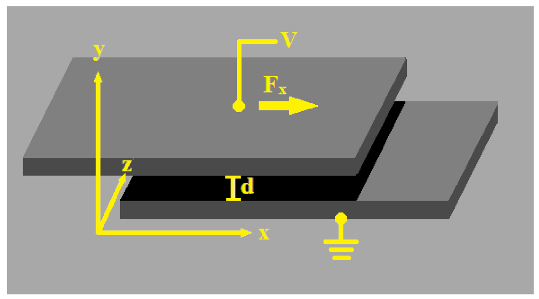
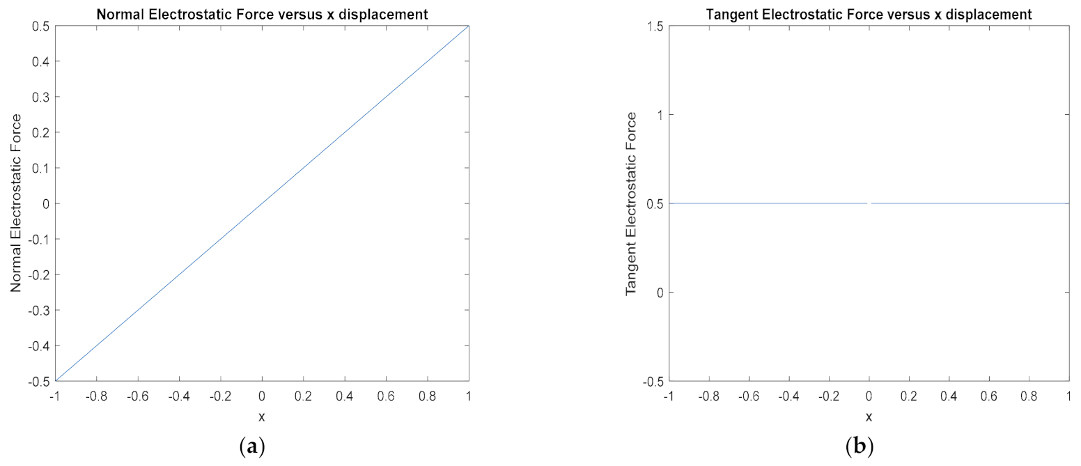
If we analyze the change in forces with respect to the change in the crossover of electrodes denoted as ‘x’, we can assume that we are analyzing a system that is being driven by tangential forces since they move along this axis. Here, we can see that the normal forces in Figure 18a are increasing linearly with respect to increases in x which pull towards the y direction. However, since y is stationary, held constant by a thin filament, we assume that these are contact forces that will increase the fictional forces in the driving ‘x’ direction. These forces will need to be canceled or minimized by designing rigid comb structures, such as in Figure 5, as they start to exceed the tangential driving forces. Now, looking at the tangential driving forces as the ‘crossover’ of electrodes increases, we can see that they remain at a constant value no matter how much they actuate (Figure 18b). This means that we can accurately control the force we apply to the system by simply increasing the voltage.
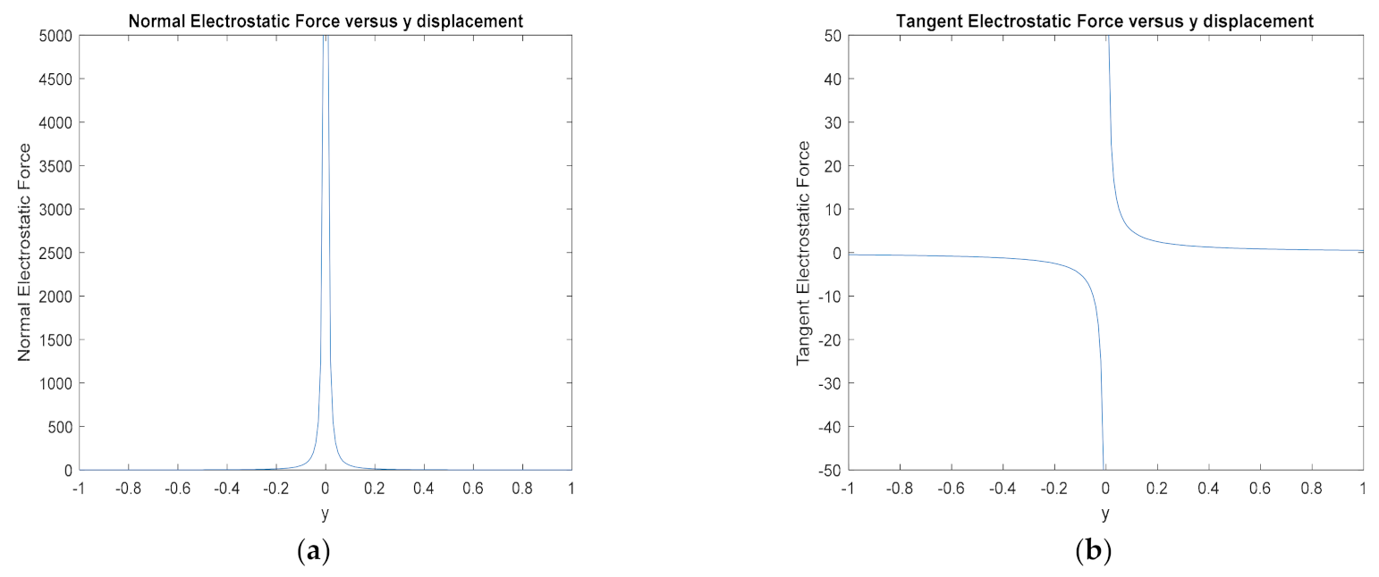
Now, looking at the forces with respect to the change in the distance between electrodes ‘y’, we can assume that the normal forces are the driving forces in this case, as it is along the same axis of displacement. The normal forces, in Figure 19a, are extremely small; however, as the electrodes approach each other there is an inflection point, such as on an exponential scale, where the forces tend towards infinity. Thus, these forces can be very strong, though they will not actuate long distances due to the rapid dissipation at distance, which is where the zipping mechanism overcomes this issue by always having a portion of the electrode close together. This, however, also shows that, once these forces reach the inflection point, the system will become unbound, and the electrode rapid ‘pull in’ to full actuation, meaning that there is no control of how much actuator (as well as zipping) will occur. The tangent forces in Figure 19b seem to operate much the same as the normal forces, however, since the center of the electrodes are often aligned, in the normal driven designs, these forces are usually canceled out.
From our mathematical analysis, we were able to determine that, by driving our actuator with normal forces, we can get much higher forces; however, the force cannot be applied at a distance. As well as this, there is no control of the displacement once it passes the ‘pull-in’ transition position. With tangential driven actuators, we have demonstrated that the potential applied force will generally be lower than the normal forces to keep the frictional forces caused by the normal forces from opposing the actuator. However, we can achieve a much higher strain, as the force is a constant no matter how much or little the crossover of the electrodes are, as well, because of the constant force, so we have easy control over the actuation distances (or strain) because the only other independent variable is the voltage.

3.2. FEM Analysis

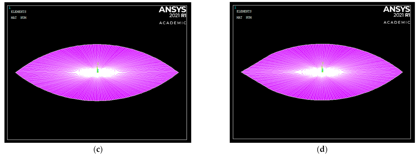
To perform our analysis of the HASEL actuators, we will be comparing the zipping mechanism with the sliding mechanism, as one represents a normal force driven system (the zipping mechanism), and the other represents a tangent force driven system (the sliding mechanism). We were able to model the geometry of the structural elements, the light blue elements in Figure 20a,b outlining the structure of the HASEL pouch, and the transducer elements (non-structural) that represent the electrostatic forces, the red elements in Figure 20a,b, with the properties of BOPP film and mineral oil shown in 
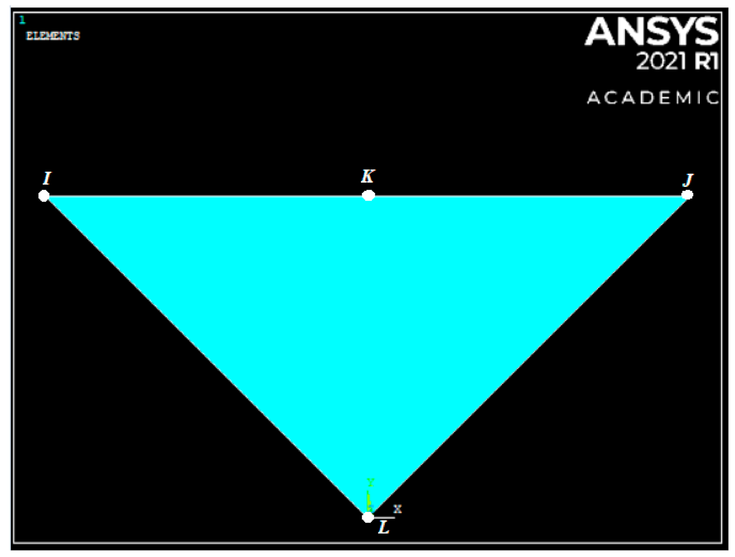
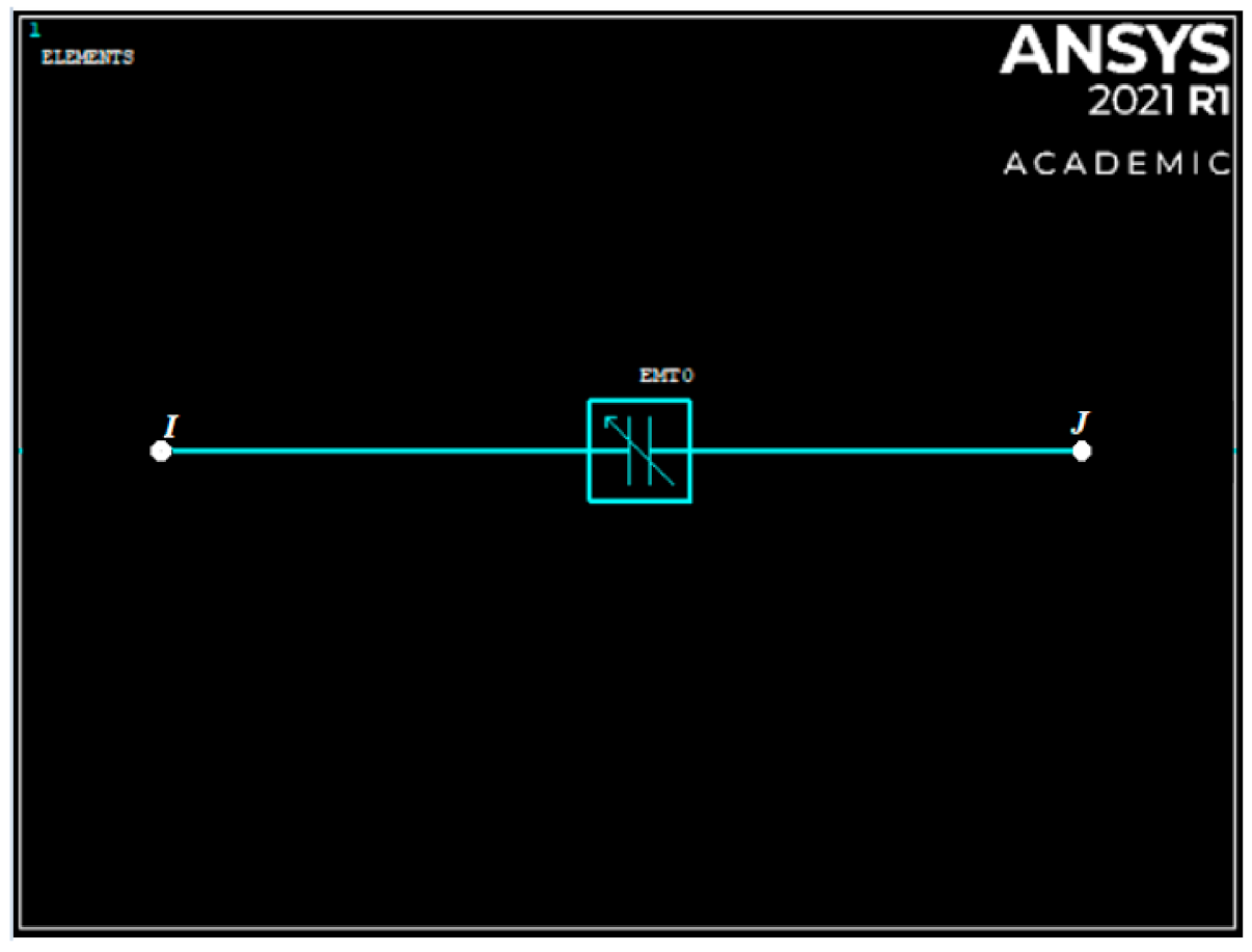
Table 2. The sliding mechanism model in Figure 20a has one transducer element (TRANS126) that represents the capacitance between the integrated electrodes and produces a force which displacements the pouch based on the voltage difference between nodes ‘i’ and ‘j’, as shown in Figure 16. With this TRANS126 element, we can also set the maximum amount of displacement the nodes of the element can achieve before the electrodes have contacted each other. Thus, there is no need to model the electrode structurally at all as it is fully represented with the one TRANS126 element (see Figure 20a). The zipping mechanism, on the other hand, in Figure 20b, requires an array of transducer elements as its capacitance varies as the distance between the electrodes varies. The hydrostatic element HSFLD241 can be seen in Figure 20c,d, shown in purple. For the zipping mechanism in Figure 20b,d, we can see that the curved geometry of the pouch has been straightened where the transducer elements are located so that we can reduce the bending required of beam elements before contact between electrodes has been made so that the model can converge easier, the voltage was also varied across the electrode to avoid penetration due to excessive forces. For our analysis, we assumed that a free strain load (zero opposing forces) is attached to the end node on the right of the image shown in Figure 20a,b, which we will refer to as the load node.
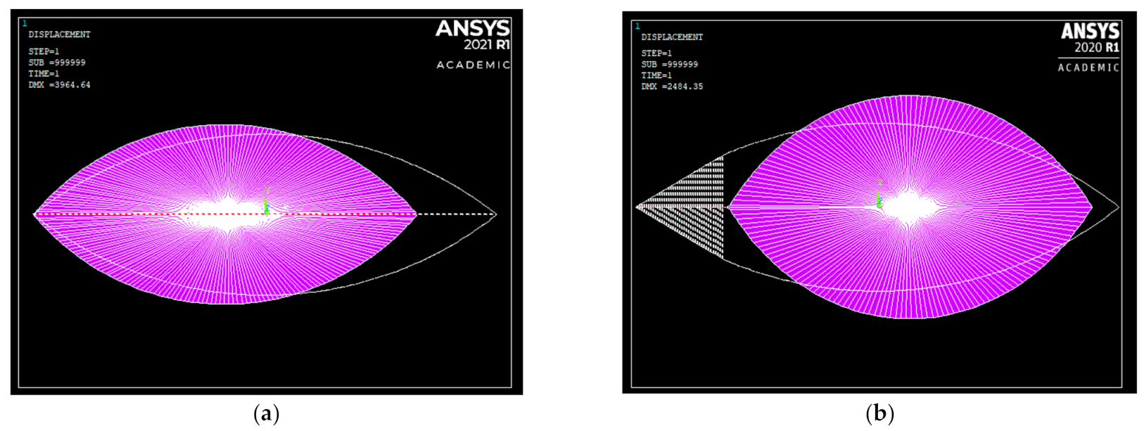
With the post-FEM analysis displacement overlapped over the pre-strain in Figure 21, we can observe that the sliding mechanism has a higher displacement then the zipping mechanism in terms of where the assumed load would be attached at the end of the pouch shown in Figure 20a,b. The zipping mechanism seems to have a lot of displacement in areas that are not at the region where the load is. To see where this displacement has been distributed throughout the pouch, we can analyze the following contour displacement plot of our FEM analyze.
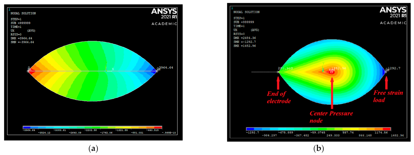
The first contour plot in Figure 22 shows the ‘x’ component of the displacement (which is from right to left) throughout the pouch structure. For the sliding mechanism in Figure 22a, the highest negative displacement was −3964.96 µm, shown in dark blue, and the highest positive displacement was 0 µm, shown in red. As we can see, the primary electrostatic displacement, and all the strain produced by the TRANS126 element, is contracting in the same direction as the secondary hydrostatic strain. This clearly demonstrates the importance of a good coupling between the primary electrostatic forces and the secondary hydraulic forces as, firstly, the highest displacement is at the load point node; secondly, there is zero strain going in the direction opposite the displacement at the load; and, thirdly, there is a uniform transmission of hydrostatic force throughout the structure from the highest to lowest displacements. With the displacement at the load node and the initial chord length of the arc, which is 23178 µm, we can calculate the strain to be −17.11%, where the negative sign demonstrates contraction.
With the zipping mechanism in Figure 22b, we can see that the highest negative displacement is −1292.7 µm, shown in dark blue, which is located at the node where our assumed load is attached, and the highest positive displacement is 1482.96 µm, shown in red, which is located at the center pressure node (the ‘L’ node in Figure 15) at the center of the HSFLD241 elements. There is also a third nodal displacement to consider, which is the pair of nodes at the end of the array of transducer elements at the end of the electrode, which has a nodal displacement of 280.903 µm. This node is important to consider because it is the node where the effect primary electrostatic force is most evident. If we observe the displacement, in Figure 22b, between these end transducer nodes and the center pressure node, as well as the area surrounding these nodes, all the displacement is in the positive direction (where positive displacement is shown in the contour color band from the light green region to the red region). From this, we can assume that there is a positive primary electrostatic force producing a secondary hydraulic force that is extending the actuator between the transducer nodes and the pressure node. On the other hand, there is a negative displacement at the exterior of the pouch, which reaches it maximum negative displacement at the load node (where negative displacement is shown in the contour color band from the aqua region to the dark blue region). We can assume that this is due to the positive hydraulic force no longer being able to push the incompressible fluid in the enclosed structure, to the end of the load, and the fluid must push to the top and bottom of the non-stretchable pouch, resulting in a net negative displacement between the pressure node and the load node. We can assume that this is the negative secondary hydraulic force that is contracting the actuator in the opposite direction of the primary electrostatic force. This clearly demonstrates the effect of poor coupling between the primary electrostatic and secondary hydraulic forces as, on the one hand, we have a strain of 6.40% expansion in the region where primary and secondary forces are in the same direction, between the end transducer nodes and the pressure node, and we also have a strain of −5.58% contraction where the primary and secondary forces oppose one another, between the pressure node and the load node, reducing the net force and strain transmitted to the load by the primary electrostatic load applied.
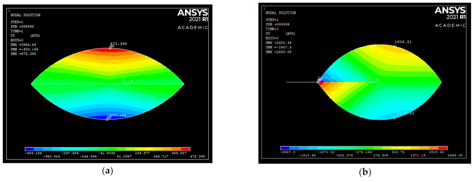
Analyzing the FEM contour plot in the ‘y’ direction shows us the displacement of the actuator in direction orthogonal to the load. The sliding mechanism in Figure 23a has its highest positive displacement of 472.4 µm (shown in red), which is approximately the same as the highest negative displacement of −453.164 µm (shown in dark blue). Much like the ‘x’ contour displacement, even though the displacements are in the opposite direction, they are both pushing away; hence, both of the secondary hydrostatic forces are producing a strain that extends the pouch in the ‘y’ plain, thus demonstrating a good coupling of primary and secondary forces. The final strain is a 11.5% expansion, where the initial length was 8048 µm. With the zipping mechanism in 
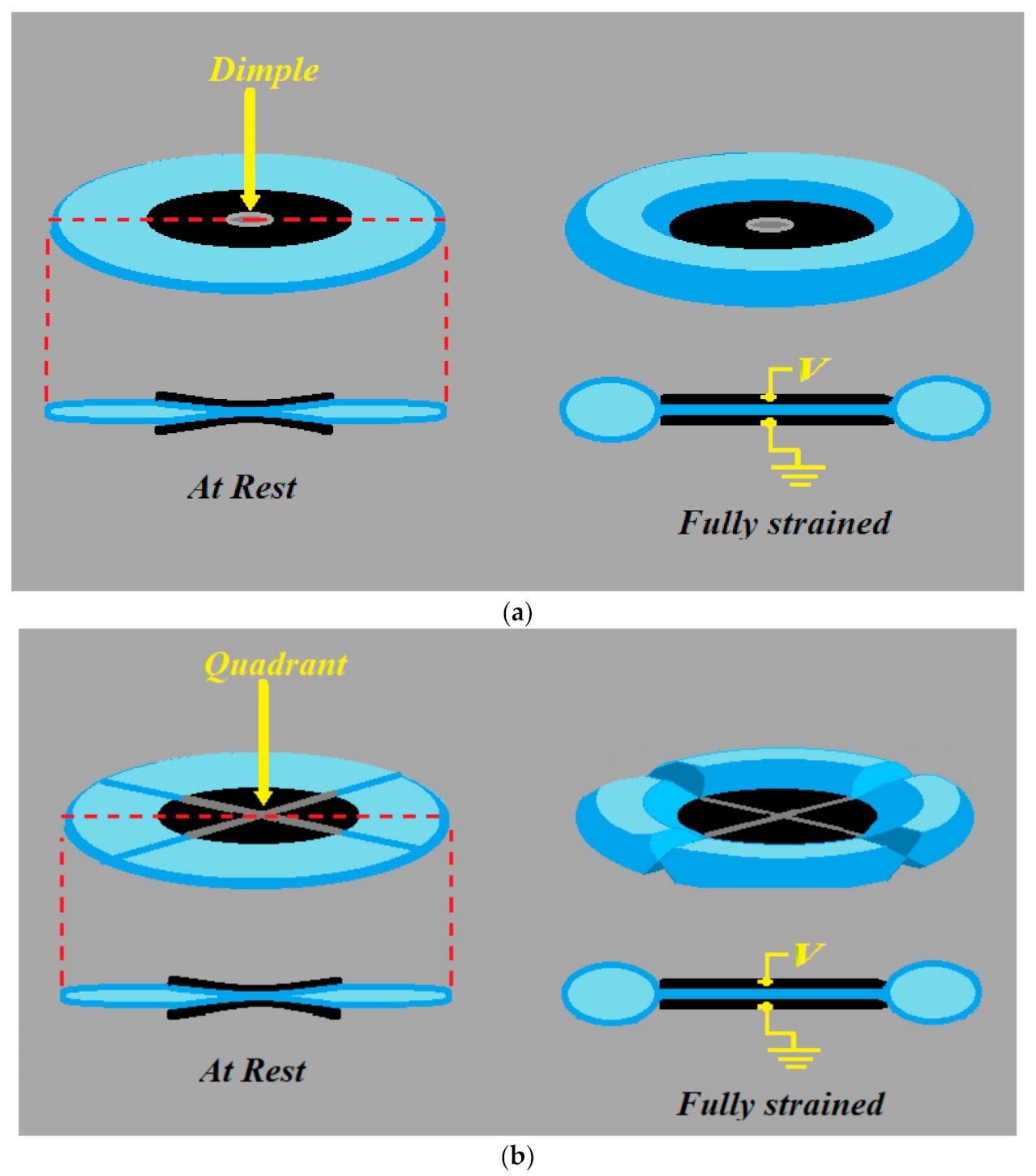
Figure 23b, the displacement seems to be separated into two sites where the displacement occurs. The primary electrostatic contraction site opposes the secondary hydraulic expansion, though, once again, the hydrostatic contraction around the electrode, ±2468.08 µm, is much higher than the hydrostatic expansion at the top and bottom of the pouch, ±1606.31 µm (where ± is the displacement at the top and bottom electrodes and pouch region). Though this is much higher than the displacement of the sliding mechanism, the fact that the contraction associated with contraction, −61.33%, site is much higher then the expansion site, 39.91%, that the load is often attached to (like with the donut, the dimple, and quadrant HASEL actuator, if you can image this geometry revolved about the electrode), we can see that coupling of primary and secondary forces can be improved upon.
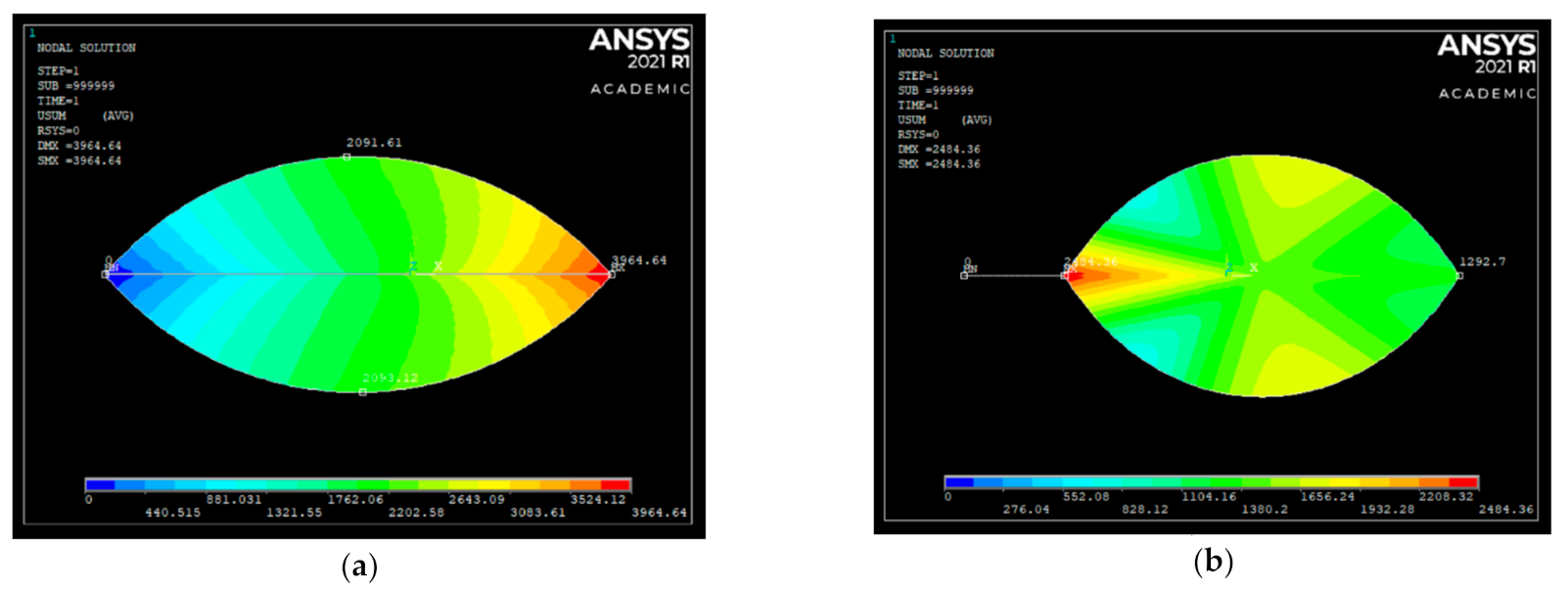
When we look at the absolute sum of all the displacement, we can see that all the displacement in the sliding mechanism is at the free strain load in Figure 24a with the maximum displacement being 3964.64 µm. This is as opposed to the zipping mechanism, which has the maximum displacement being 2484.36 µm at the end of the electrode, and displacement at the load was only 1292.7 µm, half the maximum displacement of the pouch. This once again highlights the main issue with the zipping design and its external compartmentalized design.

4. Conclusions

With this paper, we propose a new mechanism, known as the sliding mechanism, inspired by the structure of biological muscle fibers on a microscopic scale. The sliding mechanism, with its integrated electrohydraulic design, has been shown to theoretically outperform the current parallel plate mechanism and zip mechanism. We predict high force-strain characteristics due to the leveraging of tangential force produced by the electrodes. The sliding mechanism has also introduced as a new electrohydraulic principle, which allows us to bypass restrictions of current designs pertaining to the electrode length and fluid mechanics of an enclosed surface by using integrated geometries, as well as the coupling of primary electrostatic and secondary hydraulic force-strain to eliminate perpendicular forces that diminish hydraulic transmission to the load. We have also determined a new method cascading force-strain output, known as striation, which was, again, inspired by the structure of biological muscle fibers on a microscopic scale. The theory has demonstrated with mathematical analysis, as well as a FEM analysis, of the sliding and the zipping mechanism. Future research in this field will be related to implementing this mechanism by developing fabrication methods and providing an affordable supply source that meets the requirements of our sliding mechanism design.

Author Contributions

Conceptualization, L.T. and G.D.G.; methodology, L.T.; simulation, L.T.; validation, All; formal analysis, All; writing—original draft preparation, L.T.; writing—review and editing, G.N., U.G.; supervision, G.D.G. and U.G. All authors have read and agreed to the published version of the manuscript.

Funding

This research received no external funding.

Data Availability Statement

Details and source files for the simulations presented in this paper are available upon request.

Conflicts of Interest

The authors declare no conflict of interest.

References

  1. Acome, E.; Mitchell, S.K.; Morrissey, T.G.; Emmett, M.B.; Benjamin, C.; King, M.; Radakovitz, M.; Keplinger, C. Hydraulically amplified self-healing electrostatic actuators with muscle-like performance. Science 2018, 359, 61–65. [Google Scholar] [CrossRef] [PubMed] [Green Version]
  2. Kellaris, N.; Gopaluni Venkata, V.; Smith, G.M.; Mitchell, S.K.; Keplinger, C. Peano-HASEL actuators: Muscle-mimetic, electrohydraulic transducers that linearly contract on activation. Sci. Robot. 2018, 3, eaar3276. [Google Scholar] [CrossRef] [PubMed] [Green Version]
  3. Kellaris, N.; Venkata, V.G.; Rothemund, P.; Keplinger, C. An analytical model for the design of Peano-HASEL actuators with drastically improved performance. Extrem. Mech. Lett. 2019, 29. [Google Scholar] [CrossRef]
  4. Mitchell, S.K.; Wang, X.; Acome, E.; Martin, T.; Ly, K.; Kellaris, N.; Venkata, V.G.; Keplinger, C. An Easy-to-Implement Toolkit to Create Versatile and High-Performance HASEL Actuators for Untethered Soft Robots. Adv. Sci. 2019, 6, 1900178. [Google Scholar] [CrossRef] [PubMed] [Green Version]
  5. Rothemund, P.; Kellaris, N.; Keplinger, C. How inhomogeneous zipping increases the force output of Peano-HASEL actuators. Extrem. Mech. Lett. 2019, 31, 100542. [Google Scholar] [CrossRef]
  6. Wang, X.; Mitchell, S.K.; Rumley, E.H.; Rothemund, P.; Keplinger, C. High-Strain Peano-HASEL Actuators. Adv. Funct. Mater. 2020, 30, 1908821. [Google Scholar] [CrossRef]
  7. Bao, M. Chapter 4—Electrostatic Actuation. In Analysis and Design Principles of MEMS Devices; Bao, M., Ed.; Elsevier Science: Amsterdam, The Netherlands, 2005; pp. 175–212. [Google Scholar] [CrossRef]
  8. Marieb, E.N.; Keller, S.M. Essentials of Human Anatomy & Physiology, Global Edition; P.Ed Custom Books: Sydney, Australia, 2017. [Google Scholar]
  9. Pham, P.H.; Hoang, K.T.; Nguyen, D.Q. Trapezoidal-shaped electrostatic comb-drive actuator with large displacement and high driving force density. Microsyst. Technol. 2019, 25, 3111–3118. [Google Scholar] [CrossRef]
  10. Malmivuo, J. Bioelectromagnetism Principles and Applications of Bioelectric and Biomagnetic Fields; Oxford University Press: New York, NY, USA; Oxford, UK, 1995. [Google Scholar]
  11. Elger, D.F. Engineering Fluid Mechanics, 12th ed.; Wiley: Hoboken, NJ, USA, 2019. [Google Scholar]
  12. Film, M.P. Comparative Data for Plastic Films. Available online: https://www.m-petfilm.de/en/service/comparative-data-for-plastic-films/ (accessed on 19 February 2021).
  13. Ansys® Mechanical APDL. Release 18.1, Help System, Element Reference; ANSYS, Inc.: Canonsburg, PA, USA, 2020. [Google Scholar]
  14. Pu, S. A Micromachined Zipping Variable Capacitor. Ph.D. Thesis, Imperial College London, London, UK, 2010. [Google Scholar]
  15. Guru, B.S.; Hiziroǧlu, H.R. 4.3 An Ideal Transformer. In Electric Machinery and Transformers, 3rd ed.; Oxford University Press: Oxford, UK, 2000. [Google Scholar]
Figure 1. (a) The design for the donut actuator; (b) the design for the stretchable planar [1] HASEL (Hydraulically amplified self-healing electrostatics) actuator; (c) the strain achieved by 5 donut HASEL actuators stacked on top of each other.
Actuators 10 00038 g001
Figure 2. (Above) The design for the peano HASEL actuator with the zip mechanism [2].
Actuators 10 00038 g002
Figure 3. (Above) The design and operation of (a) the dimple and (b) quadrant mechanism with the zip mechanism [4].
Actuators 10 00038 g003
Figure 4. (Above) The high strain peano actuator from rest state to free strain condition [6].
Actuators 10 00038 g004
Figure 5. This is a view of a muscle fiber under various orders of magnification [10].
Actuators 10 00038 g005
Figure 6. Depiction of the comb drive actuator where the movable electrode moves towards fixed electrode under voltage, shown in red.
Actuators 10 00038 g006
Figure 7. Cross-section view of the compartmentalized geometry at rest (see top row) and under free strain conditions showing primary electrostatic site and secondary hydraulic site for the parallel plate mechanism and the zipping mechanism, as well as showing the integrated geometries ‘electrohydraulic’ site associated with the sliding mechanism. We can also see the difference in displacement ‘x’ across all three geometries.
Actuators 10 00038 g007
Figure 8. (Above) [3] (a) Depiction of the electrode coverage for the peano HASEL design with the zip mechanism. (b) Depiction of the electrode coverage of the sliding mechanism.
Actuators 10 00038 g008
Figure 9. (Above) [3] Graphical depiction of the decay of the free strain ‘ϵf’ ( the blue line) and growth of the blocking force ‘FB’ ( the red line) as electrode coverage ‘fe’ is increased for the peano HASEL actuator.
Actuators 10 00038 g009
Figure 10. (a) Depiction of the electrode coverage of the unintegrated electrohydraulic coupling with the zip mechanism and parallel plate mechanism geometries (b) and the integrated electrohydraulic coupling, like the slide mechanism geometry.
Actuators 10 00038 g010
Figure 11. (a) The maximum theoretical secondary hydraulic transmission of the zip mechanism as depicted by the peano actuator design and (b) the maximum theoretical secondary hydraulic transmission of the sliding mechanism.
Actuators 10 00038 g011
Figure 12. Cross-sectional view of HASEL actuators under no strain or at rest (see top row) and their “free strain” contraction and expansions due to primary electrostatic force-strain ( F p and ϵ p ) generation and secondary hydraulic force-strain ( F s and ϵ s ) transmission for each mechanism as follows (a) the parallel plate mechanism, (b) the zipping mehcanism, and (c) the sliding mechanism.
Actuators 10 00038 g012
Figure 13. (a) A representation of the HASEL actuators arc segment radius (ro), arc segment length (Lp), arc segment angle (αo), and the electrode coverage (Le). (b) A representation of the HASEL actuators′ width (w) and arc segment length (Lp) [3].
Actuators 10 00038 g013
Figure 14. The geometry of the structural BEAM189 element with the three nodes ‘I’, ’J’, and ‘K’ [13].
Actuators 10 00038 g014
Figure 15. The geometry of the hydrostatic HSFLD241 element with the surface nodes ‘I’ and ‘J’, as well as the pressure node ‘L’ [13].
Actuators 10 00038 g015
Figure 16. The configuration of a TRANS126 element [13].
Actuators 10 00038 g016
Figure 17. A depiction of the parallel plate relative the XYZ coordinate system.
Actuators 10 00038 g017
Figure 18. (Above) (a) Graph of the Electrostatic normal force with respect to changes in electrode crossover. (b) Graph of the Electrostatic tangent force with respect to changes in electrode crossover
Actuators 10 00038 g018
Figure 19. (Above) (a) Graph of the Electrostatic normal force with respect to changes in distance between the electrodes (b) graph of the Electrostatic tangent force with respect to changes in distance between the electrodes.
Actuators 10 00038 g019
Figure 20. (Above) (a) Pouch geometry for the sliding mechanism with the structural element BEAM189 represented by the light blue elements, and the transducer element TRAN126 represented by the red elements. (b) Pouch geometry for the zipping mechanism with the structural element BEAM189 represented by the light blue elements, and the transducer element TRAN126 represented by the red elements. (c) The hydrostatic elements of sliding mechanism which is attached to the BEAM189 element; (d) the hydrostatic elements of the zipping mechanism with the straight structure where the TRANS126 elements would be attached.
Actuators 10 00038 g020aActuators 10 00038 g020b
Figure 21. (Above) (a) Sliding mechanism post-FEM analysis displacement, with the hydrostatic element HSFLD241 represented by the purple area, overlapped with the pre-FEM analysis model, where the electrostatic element TRANS126 is represented by the white dotted line through the middle of the pouch. (b) Zipping mechanism post-FEM analysis displacement, with the hydrostatic element HSFLD241 by the purple area, overlapped with the pre-FEM analysis model, where the electrostatic element TRANS126 is represented by the white dotted lines along the left side of the pouch.
Actuators 10 00038 g021
Figure 22. (Above) (a) Sliding mechanism post-FEM analysis contour plot of the displacement of the structure ‘x’ direction from the highest displacement in the positive direction (in red) and the highest displacement in the negative direction (displayed in µm). (b) Zipping mechanism post FEM analysis contour plot of the displacement of the structure ‘x’ direction from the highest displacement in the positive direction (in red) and the highest displacement in the negative direction (displayed in µm).
Actuators 10 00038 g022
Figure 23. (Above) (a) Sliding mechanism post FEM analysis contour plot of the displacement of the structure ‘y’ direction from the highest displacement in the positive direction (in red) and the highest displacement in the negative direction (displayed in µm). (b) Zipping mechanism post FEM analysis contour plot of the displacement of the structure ‘y’ direction from the highest displacement in the positive direction (in red) and the highest displacement in the negative direction (displayed in um).
Actuators 10 00038 g023
Figure 24. (Above) (a) Sliding mechanism post FEM analysis contour plot of the sum of displacements from the highest absolute displacement (in red) to the lowest displacement in the negative direction (displayed in um). (b) Zipping mechanism post FEM analysis contour plot of the sum of displacements from the highest absolute displacement (in red) to the lowest displacement in the negative direction (displayed in um).
Actuators 10 00038 g024
Table 1. Geometric parameters.
ParameterValue
Arc length, LP25 mm
Arc radius, ro18.7 mm
Arc angle, αo76.5928 degrees
Electrode coverage, Le (zip geometry)0.2
Electrode coverage, Le (sliding geometry)0.6
Width, w100 mm
Film thickness, t2 µm
Table 2. Material parameters.
ParameterValue
Young’s Modulus, E (BOPP)2500 MPa
Density, ρ (BOPP)0.9 g/cm3
Relative Permittivity, εr (Mineral Oil)2.1
Voltage Potential, V8000 V
Publisher’s Note: MDPI stays neutral with regard to jurisdictional claims in published maps and institutional affiliations.

