
Investigation on a Linear Piezoelectric Actuator Based on Stick-Slip/Scan Excitation


1
State Key Laboratory of Mechanics and Control of Mechanical Structures, Nanjing University of Aeronautics and Astronautics (NUAA), Nanjing 210016, China
2
College of Mechanical and Electronic Engineering, Northwest A&F University, Yangling 712100, China
*
Author to whom correspondence should be addressed.
Actuators 2021, 10(2), 39; https://0-doi-org.brum.beds.ac.uk/10.3390/act10020039
Submission received: 28 January 2021
/
Revised: 16 February 2021
/
Accepted: 17 February 2021
/
Published: 20 February 2021
(This article belongs to the Section Precision Actuators)
Abstract
:To perform a high resolution and long stroke application in optical precision instruments, a linear piezoelectric actuator operated in stick-slip/scan modes for driving a linear motion table is presented. The proposed piezoelectric actuator is a piezoelectric composite structure, which includes a metal elastomer, a piezoelectric stack, and a frictional ball. The purpose of this paper is to describe the operation principle, design, and the running test and resolution test of the linear motion table driven by the proposed piezoelectric actuator. The notable feature is the flexible hinges of the actuator, including composite hinge, pre-pressure adjustment flexible hinge, and transmission flexible hinge, which are designed for decoupling the motion in the action direction of the piezoelectric stack and the direction in which the pre-pressure is applied. A prototype has been fabricated and two operation modes of the piezoelectric actuator, stick-slip and scan mode, were utilized to test the driving characteristics of the linear motion table. Experimental results show that the finest step resolutions in stick-slip mode and scan mode achieved 12 nm and 4 nm, respectively.
1. Introduction
Operating processes on objects at micro-scales need high-precision motion servo systems. Moreover, the requirements for the resolution and travel of linear motion systems are also increasing with the rapid development of technology. For example, wafer processing or testing equipment has a higher demand in resolution and travel. To meet these requirements, numerous variations of micro-motion device technology have been developed [1,2,3]. Among these, piezoelectric actuators are one type of prevailing micro-actuation technology, which have been widely used in linear precision motion stages [4] for their inherent characteristics of compact sizes, high displacement resolutions, self-locking when power is off, fast response, lower thermal generation, and high electromagnetic immunity.
Piezoelectric actuators produce force and displacement by using the inverse piezoelectric effect of the piezoelectric element. Generally, the deformation of the piezoelectric element, even as a multilayer piezoelectric stack, is very small (micron) compared to their size [5,6]. To achieve long travel actuation, many piezoelectric actuators with different operation principles were developed, which can be divided into four main categories: ultrasonic motors, piezoelectric compliant mechanism, inchworm motors, and inertia motors: (1) the typical configurations for ultrasonic motors are the traveling wave type [7,8,9] and the standing wave type [10,11,12,13,14,15]. The working principle of the ultrasonic motor is almost based on a piezoelectric actuator, which utilizes piezoelectric elements to activate the desired vibration of an elastic body, and the driving points of the elastic body perform elliptical motions at a frequency in the ultrasonic range. A slider or rotor, pressed on the driving points of the vibrating body by a normal force, is driven by a friction force to achieve linear motion and rotation motion. Herein, the linear ultrasonic motor is mostly a standing wave type, which is mainly driven by multi-modal coupling or single-modal. The resonant frequency of the ultrasonic motor varies with the operating temperature; thus, the performance of the motor is greatly affected by the driving frequency. (2) A piezoelectric compliant mechanism is a device that moves solely by deformation, typically driven by multiple piezoelectric stacks [16,17]. The travel of this actuation method is still very small, mostly limited to 1 mm. (3) Piezoelectric inchworm motors are designed by imitating the inchworm moving characteristics of the insets in the nature [18,19,20,21], which usually use multiple PZT stacks together with a flexible hinge with the function of displacement amplification to implement actuation and clamping. This type of actuator may be more promising for achieving large force and long stroke actuation due to the large thrust characteristic of the piezoelectric stack; however, it requires high machined accuracy and assembly accuracy on the contact surface between the guiding groove surface and the piezoelectric actuation element. (4) Inertia motors, or stick-slip motors, utilize the friction/inertia nature of their components to generate motion [22,23,24,25,26,27,28]; the mobile element is moved forward together with the stator smoothly because of the static friction when the stator stretches gently, but does not move back because of the inertial force when the stator suddenly shrinks; thus, the mobile element moves one step. Repeating this kind of movement continuously, one continuous movement can be achieved.
Generally, piezoelectric inertia motors or stick-slip motors have an inherent drawback of backlash due to the operation principle described above. Therefore, many researchers have conducted a series of studies on this issue and achieved good results [25,26,27]. Zhang et al. proposed an anisotropic-friction surface to restrain the backward displacement [26]. Cheng et al. developed a resonant/off-resonant hybrid excitation method to activate the piezoelectric stick-slip actuator; the driving capacity of the actuator was significantly increased by 466.13% [27]. Thus, the piezoelectric inertia motor has been drawing extensive attention for its special characteristics: firstly, it only needs one electronic channel to realize the function of actuation; secondly, it does not require any sophisticated mechanical and precision assembly processes; thirdly, comparatively speaking, the operating frequencies are not limited to a specified frequency. Furthermore, this type of motor can realize nanometer resolution and large workspaces (several cm3, theoretically unlimited displacement) and a very good level of miniaturization.
Accordingly, based on the above-mentioned advantages of the piezoelectric inertia motor, in this work, we propose a novel piezoelectric actuator performing the stick-slip/scan operation principle for precise linear servo applications. This paper is organized as follows: the construction and operation principles are presented in Section 2, followed in Section 3 by the design of the key mechanical structure of the piezoelectric actuator; then, the experiments associated with the running test in open loop and resolution test are described in Section 4; finally, the conclusion of this study is presented in Section 5.
2. Construction and Operation Principle
2.1. Construction
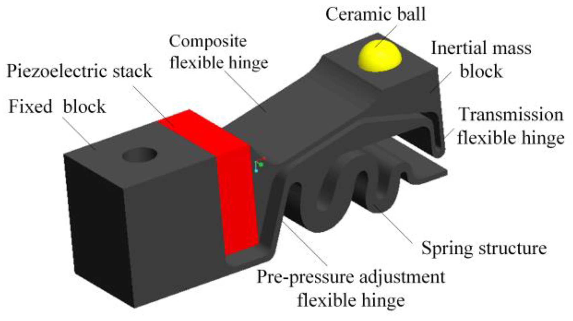
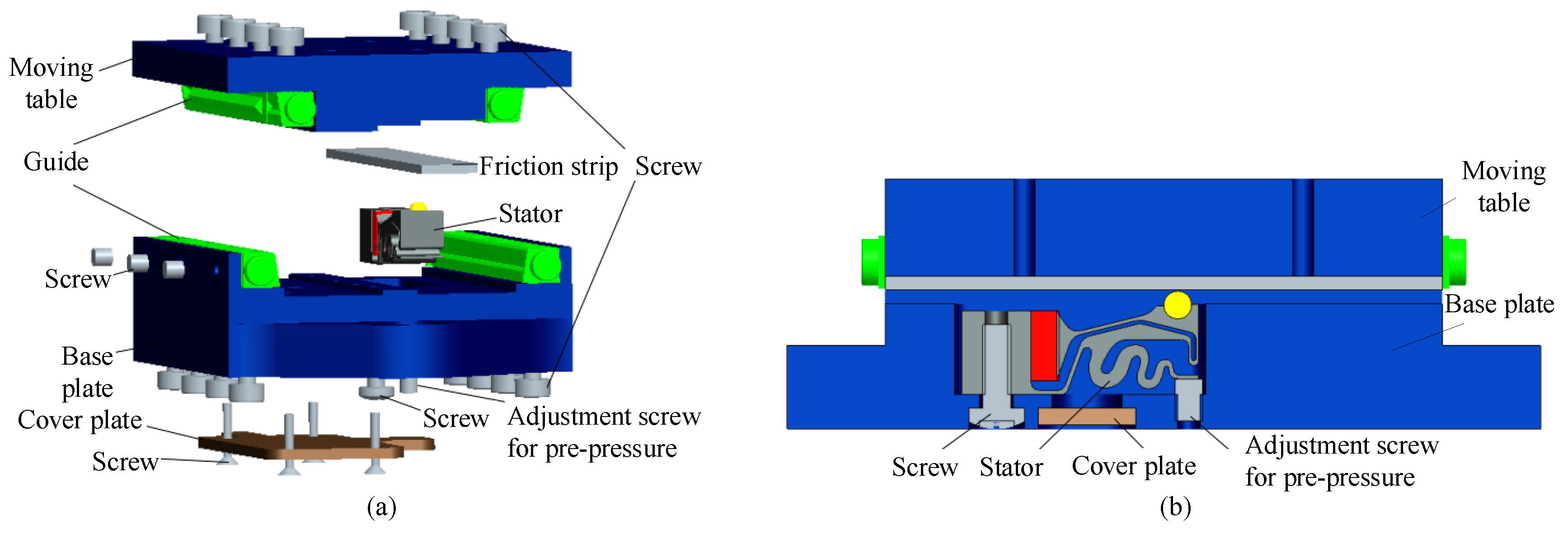
Figure 1 shows the structure of the piezoelectric actuator with a dimension of 17 × 5 × 6 mm3. The actuator includes a metal elastomer, a piezoelectric stack, and a frictional ball. The metal elastomer is composed of four parts: fixed blocks, flexible hinges, inertial mass, and spring structure. The piezoelectric stack is clamped between the fixed block and the inertial mass block. Figure 2 shows the overall structural design of the linear motion stage. The actuator is mounted on the bottom of the base plate by a screw; a ceramic strip used as a friction strip is attached at a corresponding position under the moving table; the ceramic ball at the front end of the actuator is pressed on the surface of the frictional strip by one adjustment screw; the commercially available cross roller rails are used for guiding the moving table.
For the linear motion stage driven by the proposed piezoelectric actuators, the main difficulty lies in how to decouple the motion in the action direction of the piezoelectric stack and the direction in which the pre-pressure is applied. At the same time, in order to achieve miniaturization of the motion table, it is best to integrate functional components into the overall structural design. Furthermore, for the stick-slip driving method, there is only “slip” during the stick-slip process if both contact surfaces are rigid; thus, the mobile unit cannot be effectively driven. On the other hand, there is only “stick” during the stick-slip process if both contact surfaces are flexible; thus, the moving unit will follow the motion of the actuator. The mobile unit must be rigid; therefore, the actuator should be designed as a flexible body. Here, three flexible hinges are designed for transferring the displacement of the piezoelectric stack and applying pre-pressure between this actuator and the moving table which is pressed on the frictional ball (see Figure 2b). The pre-pressure adjustment flexible hinge and the transmission flexible hinge should be designed to facilitate the transmission of displacement of piezoelectric stack and the preloading between the friction ball and the moving table, respectively. The composite flexible hinge is designed as one type of composite functional hinge, which is used for coordinating the deformation of the two flexible hinges described above.
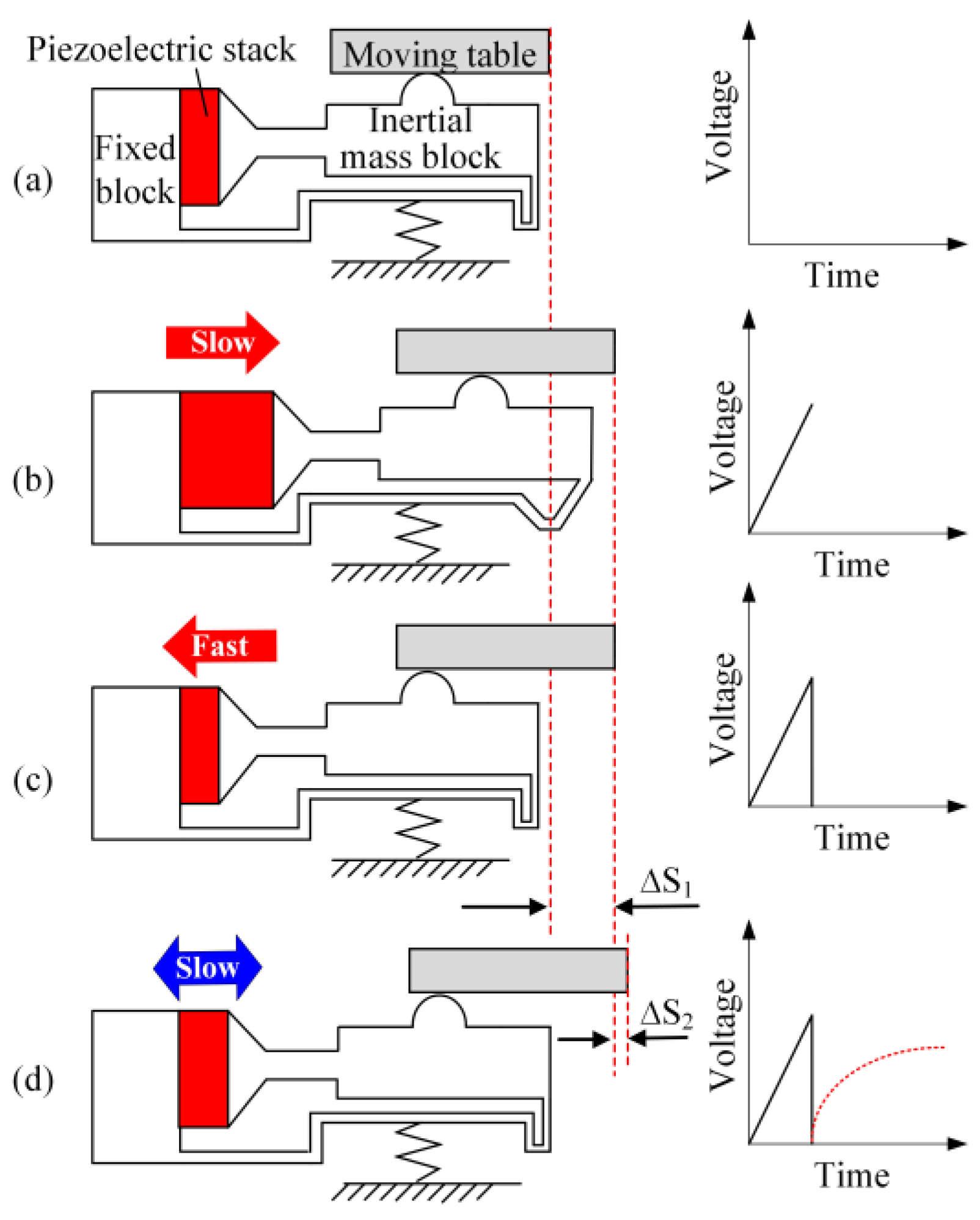
2.2. Operation Principle
The operation principle of the proposed actuator is described in Figure 3. The piezoelectric stack changes its length proportionally to the applied voltage. The moving table will follow the movement of the piezoelectric stack with the same acceleration when the piezoelectric stack is not accelerated too high; this state is called stick-phase (see Figure 3b). Correspondingly, the inertial force of the accelerated motion table is higher than the friction force if the piezoelectric stack is accelerated very high. In this case, the friction surface of the actuator slips over the surface of the motion table, and as a result, the piezoelectric stack can change its length while the moving table stays its position, which is called the slip-phase (see Figure 3c). Thus, a continuous motion can be realized by repeating the sequence from Figure 3a–c. In order to achieve a high motion accuracy, a special operation mode called scan mode can be realized by slowly elongating the piezoelectric stack during the stick-phase (see Figure 3d).
3. Actuator Design
There are three main issues that should be considered during the structural design process of this actuator: (1) the dimensional design of the composite flexible hinge to ensure the respective stiffness characteristics of the driving and pre-pressure applying directions; (2) the matching problem between the rigidity of the flexible transmission mechanism and the piezoelectric stack; (3) calculating the natural frequency of the actuator to avoid self-excitation during actuator operation.
3.1. Modeling of Actuator
Here, 65Mn was selected as the material of the metal elastic body (density is 7820 kg/m3, elasticity modulus is 2.11 × 10¹¹ Pa, and Poisson’s ratio is 0.288), and one ceramic ball made of Al2O3 was used as a friction ball (density is 3950 kg/m3, elasticity modulus is 3.55 × 10¹¹ Pa, and Poisson’s ratio is 0.27). One PZT stack (NAC2003, Noliac Company, Kvistgaard, Denmark, density is 7650 kg/m3, elasticity modulus is 0.9 × 10¹¹ Pa and Poisson’s ratio is 0.3) was chosen as the piezoelectric component, which had a size of 5 × 5 × 2 mm3, output displacement up to 2.6 μm at 60 V, and stiffness up to 350 N/µm. The finite element model of the actuator is shown in Figure 4.
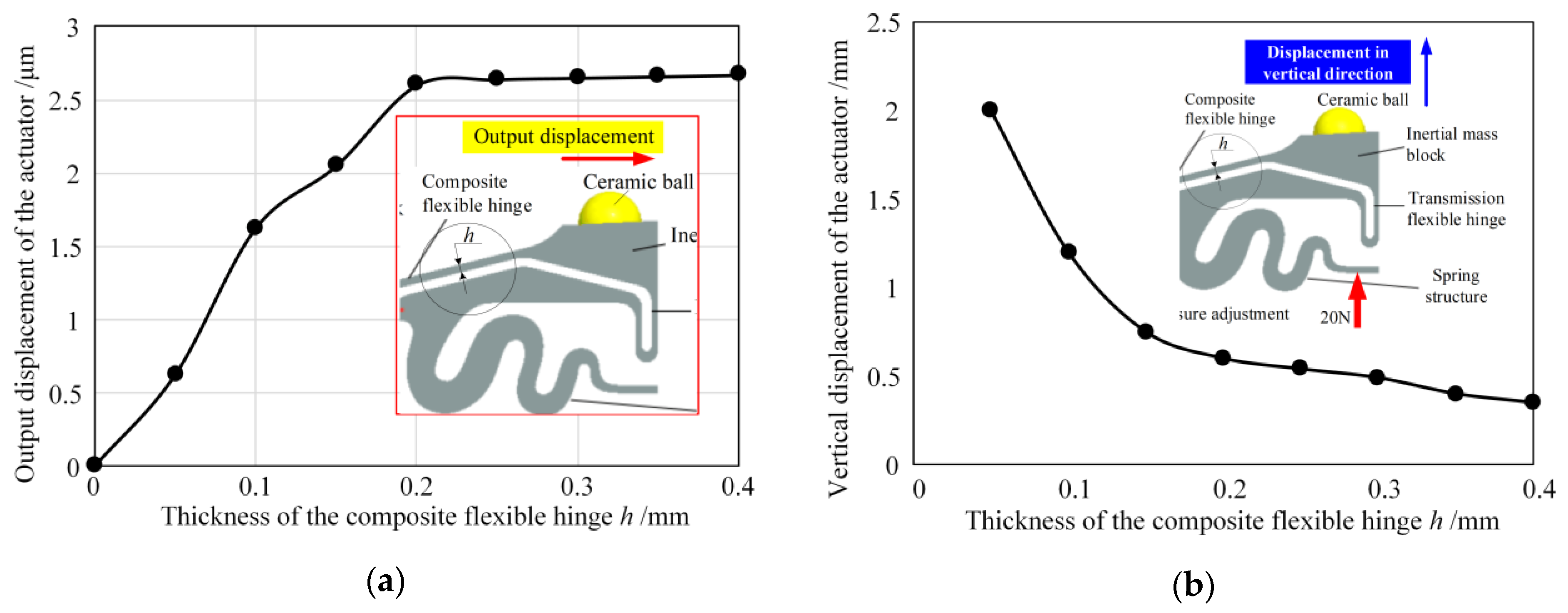
3.2. Composite Hinge Design
Due to the limitation of the already selected piezoelectric stack (5 × 5 × 2 mm3) and the overall size of the motion table, the length and width of the composite hinge have been determined to be 5 mm. Therefore, this section focuses on the thickness design of the hinge. The influences of the thickness of the composite flexure hinge on the output displacement of the actuator and the vertical displacement of the inertial mass block under the pre-pressure of 20 N are analyzed through the workbench software (see Figure 5). It can be seen from Figure 5a that the output displacement of the actuator linearly increases with the hinge thickness from 0 to 0.2 mm, and when the hinge thickness reaches more than 0.2 mm, the output displacement of the actuator gradually approaches the maximum output displacement of the piezoelectric stack. From Figure 5b, it can be seen that the displacement of the inertial mass block in the vertical direction under the fixed pre-pressure of 20 N decreases with the hinge thickness from 0 to 0.2 mm and gradually becomes stable when greater than 0.2 mm. Therefore, synthesizing the strength requirements, the thickness of the composite flexible hinge was selected to 0.25 mm. When the input displacement is 2.6 μm, the output displacement of the actuator also achieved 2.6 μm.
3.3. Model Analysis
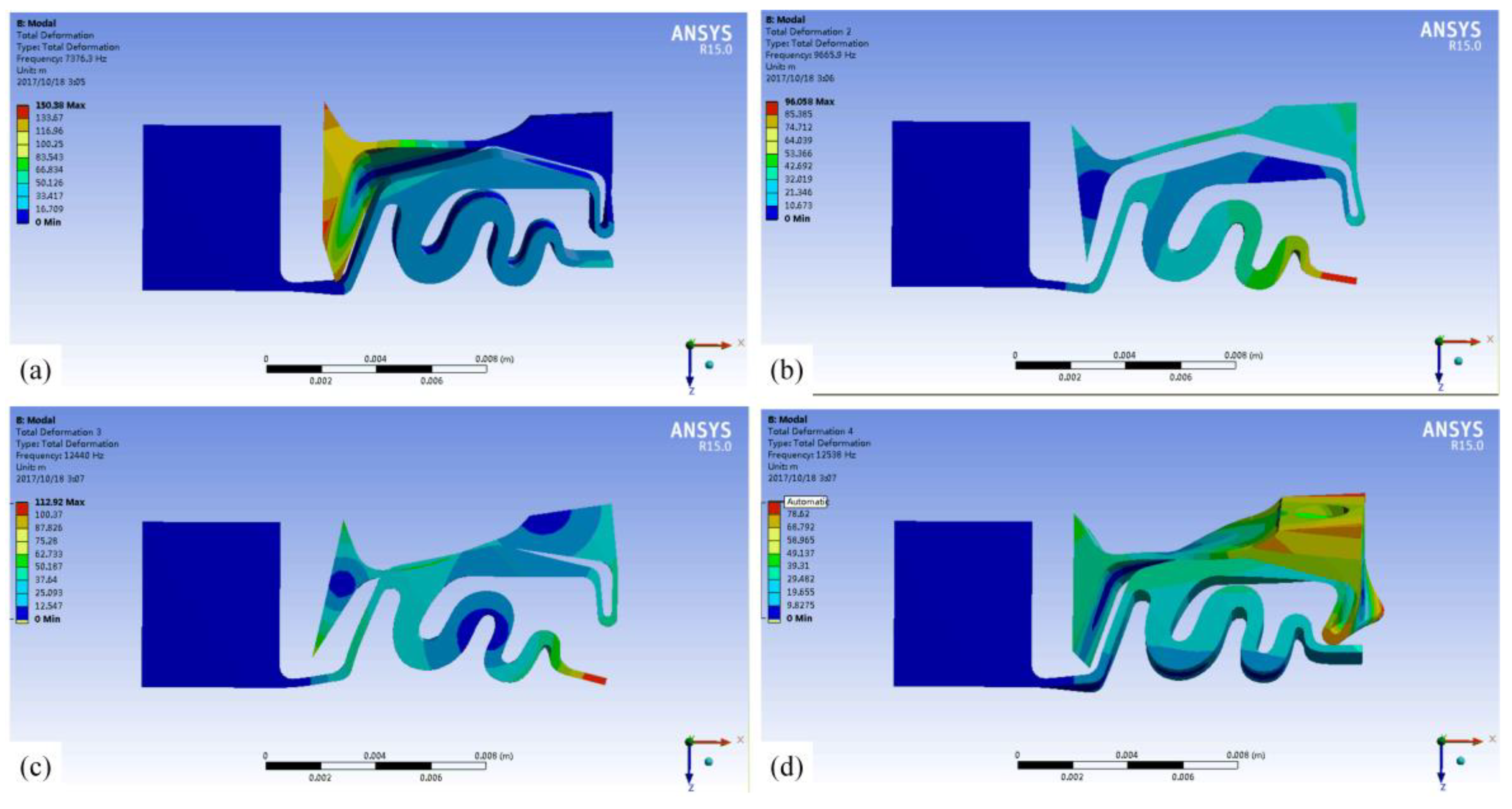
According to the working principle, in order to prevent the elastic metal element of the actuator from being excited to resonance state when the piezoelectric stack is excited, it is necessary to conduct modal analysis on the actuator without a piezoelectric element. Figure 6 shows the model analysis results. The natural frequencies of the first mode to the fourth mode are 7376 Hz, 9666 Hz, 12,440 Hz, and 12,538 Hz, respectively. It is clear that if the inherent modes shown in Figure 6 are excited, the elastomer of the actuator will produce undesirable deformation, resulting in abnormal operation or damage of the actuator. Therefore, the operating frequency of the actuator must be less than 7376 Hz, or between the above and subsequent model frequencies.
3.4. Stiffness Calculation of Transmission Flexible Hinge
Here, it can be seen from the actuator structure that the stiffness of the transmission flexible hinge has a great influence on the actual output displacement of the actuator (see Figure 1). In theory, the smaller the stiffness of the flexible drive mechanism, the less influence on the actual output displacement of the actuator. However, pure piezoelectric ceramics can produce high pushing forces, but cannot withstand high tensile forces.
As for the proposed inertia actuator, the resetting force must be introduced into the system to achieve a more symmetrical push–pull performance. Moreover, the preload mechanism for resetting force should provide a high force but with a stiffness as low as possible; the preload force, therefore, does not vary with the piezo element’s motion and the maximum stroke can thus be achieved. At the same time, the resetting force is required to be high enough to reset the mass block attached to the actuator fast enough. Generally, a passive preload mode by using the transmission flexible hinge is often utilized for providing the resetting force of the piezoelectric stack. Usually, to achieve symmetrical push–pull performance, the preload force applied sometimes on the piezoelectric stack ceramics is up to 50% of actuator’s maximum load capability, and the preload stiffness is a few percent of the piezoelectric stack’s stiffness. Therefore, in order to meet the above requirements, the stiffness of the transmission flexible hinge of the designed actuator was calculated as shown in Figure 7.
Here, the constraint of the fixed block is set as a fixed constraint. The end of the spring structure is in contact with the pre-pressure adjusting screw, so the only movement in the driving direction is allowed at the end of the elastic element. Thus, when a force of 50 N along the driving direction is applied to the end face of the composite flexible hinge, the inertial mass block produces a displacement of 91.5 μm along the driving direction. Then, the stiffness of the transmission flexible hinge in the driving direction is 50 N/91.5 μm = 0.546 N/μm, which is much less than the stiffness of the adopted piezoelectric stack (350 N/μm). Hence, at this stiffness level, the actual output displacement of the actuator is approximately the output displacement of the piezoelectric stack. Generally, the preload should be high enough, but not too high, to avoid depolarization. Thus, we choose 10% of the maximum output force of the piezoelectric stack as its pre-load. Here, the maximum output force of the adopted piezoelectric stack is 1050 N, so the pre-load of the stack should be about 100 N, and the mounting space of the piezoelectric stack should have a pre-deformation of about 0.18 mm (100 N/0.546 N/μm).
4. Experimental Investigation
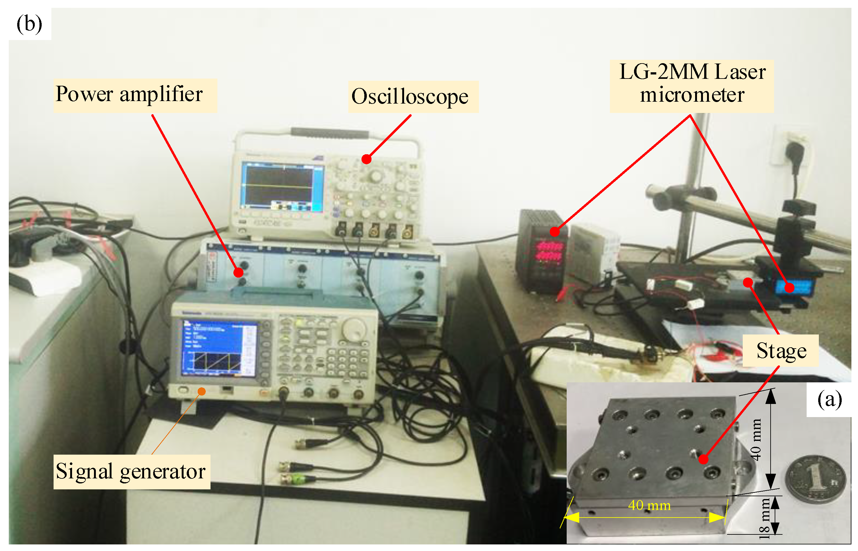
The prototype of the motion table driven by the proposed actuator was fabricated as shown in Figure 8a. The overall size of the motion table was 40 × 40 × 18 mm3, with a mass of about 32 g and a maximum stroke of 22 mm. A test system was built to measure the performance of the motion table, as shown in Figure 8b. One signal generator (AFG3022C, Tektronix Co., LTD. Suzhou, China) was utilized to produce a driving signal and amplified by a power amplifier to drive the actuator, and one oscilloscope was used to monitor the change of the driving signal. The dynamic and static characteristics of the stage were investigated by using a laser micrometer (LG-2MM, KEYENCE CORPORATION, Shanghai, China) with a measuring range of 2 mm; the maximum measuring range can be up to 10 mm with a different probe.
4.1. Running Test of Motion Table in Open Loop
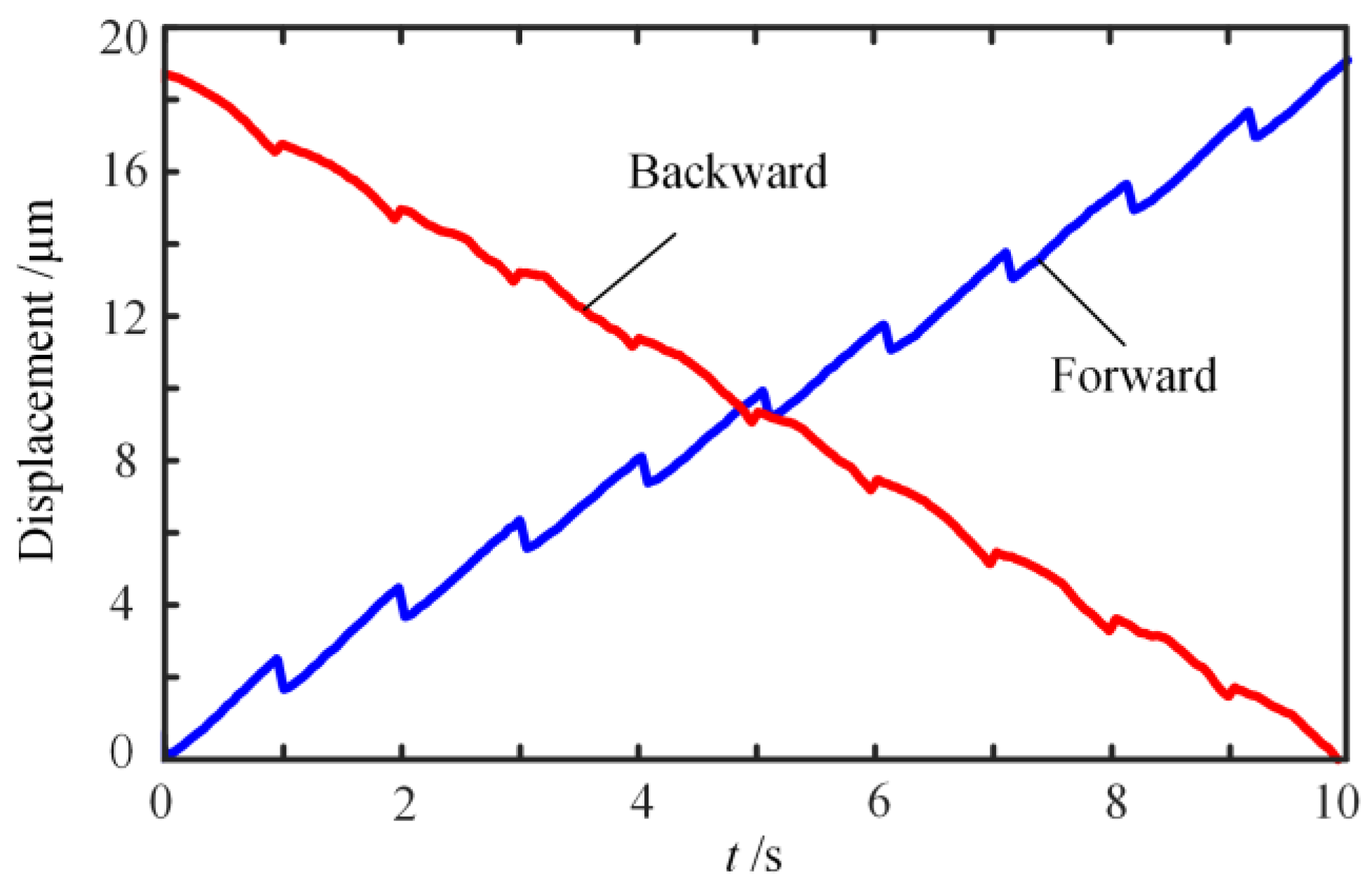
In the process of the running test, a sawtooth wave signal with an amplitude of 60 V, frequency of 1 Hz, and step time of 30 ms was adopted to activate the actuator. At the same time, the sampling frequency of the laser micrometer was set to 1 kHz. The test results are shown in Figure 9. It can be observed that both the forward and backward motions are in the form of sawtooth waves, in which the average step size of the forward motion is 1.841 μm, while the average step size of the backward motion is 1.766 μm. It is known that the piezoelectric element has a characteristic of capacitive load. Herein, in the case of the driving circuit having no discharge loop, the charge time constant of the stator equals the discharge time constant; the response of the stator cannot keep up with the changing of the driving signal.
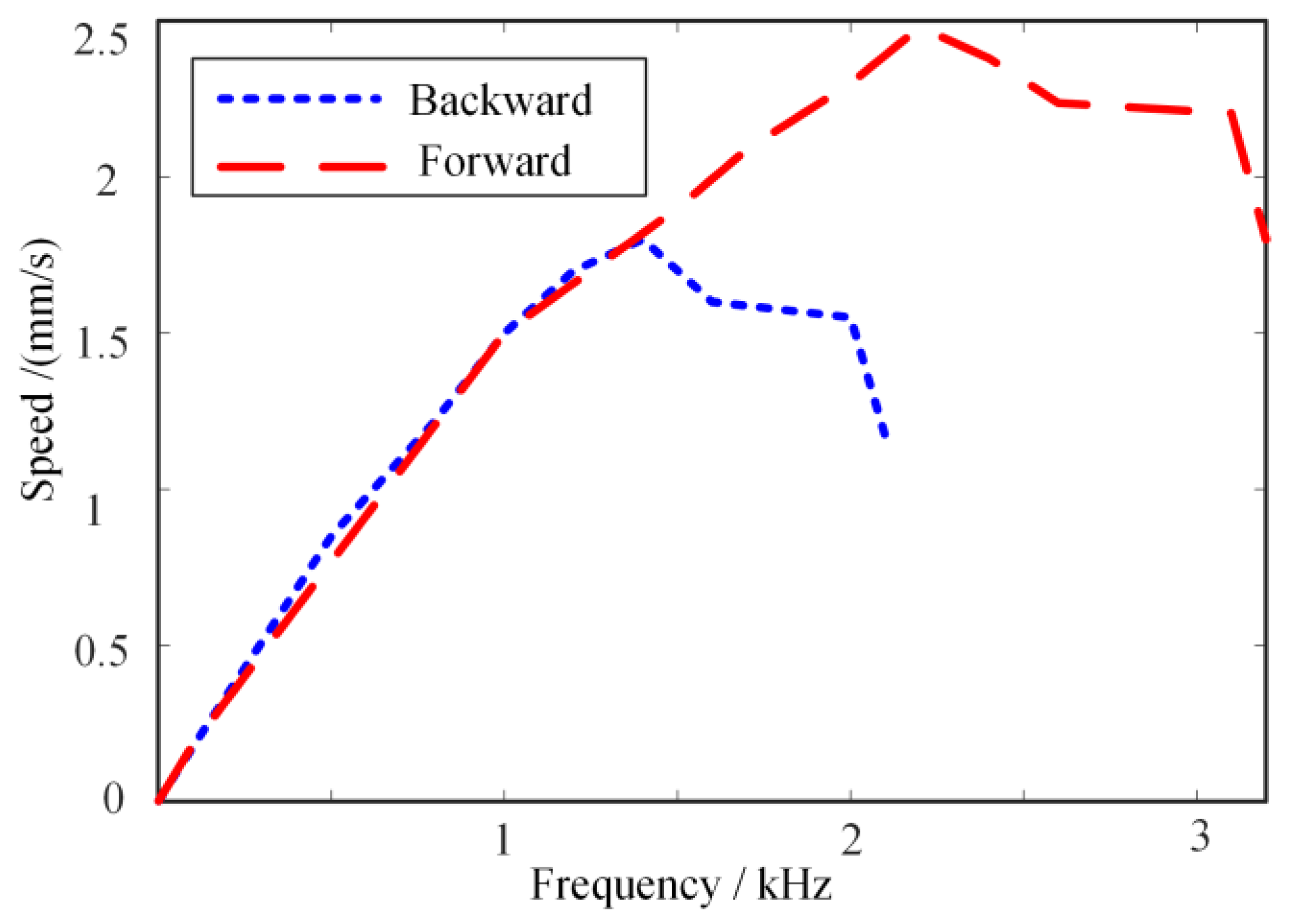
To solve this problem, the discharge circuit was used to improve the response characteristics of piezoelectric elements and achieved good results [28]. Therefore, we also developed a driving circuit with a discharge loop to improve the response characteristics of this proposed actuator and achieved the desired results (see Figure 10). Figure 10 shows the speed characteristics of the stage under different driving frequencies. Here, a series of sawtooth wave signals with an amplitude of 60 V, frequencies of 0~1000 Hz, and a step time of 30 ms were adopted to drive the actuator. The sampling frequency of the laser micrometer was set to 5 kHz. Both the forward and backward speed of the stage changed linearly with the driving frequency when the driving frequency changes from 0 to 1 kHz; however, when the driving frequency was above 1 kHz, the reverse speed increased slowly and reached its maximum speed of 1.8 mm/s at 1.4 kHz and the forward speed reached its maximum speed of 2.5 mm/s at 2.2 kHz. The main reason for the difference was that the push–pull performance of the actuator was not completely symmetric due to the differences between the elongation and contraction characteristics of the piezoelectric stack.
4.2. Resolution Test
To achieve precise motion, the stepping operation mode of the actuator is usually used. By controlling the number of the driving signal, different resolutions can be obtained. Figure 11 presents the stepping test results of the stage in open-loop operation mode. Here, the driving signal is a sawtooth wave with a frequency of 100 Hz, and voltage amplitude of 2.2 V. Driven by a signal train of 0.1 s (driving signal cycle number is 10) for a driving period of 5.1 s, the finest resolution of 100 nm was achieved (see Figure 11a). Driven by a signal train of 0.01 s (driving signal cycle number is 1) for a driving period of 5.1 s, the finest resolution of 12 nm was achieved (see Figure 11b). There is a slight difference in the step displacement between the forward and backward directions. The reasons are mainly in addition to the asymmetric push–pull performance of the actuator; there are slight differences in the surface quality of the friction interface between the ceramic ball and the friction plate bonded on the motion table.
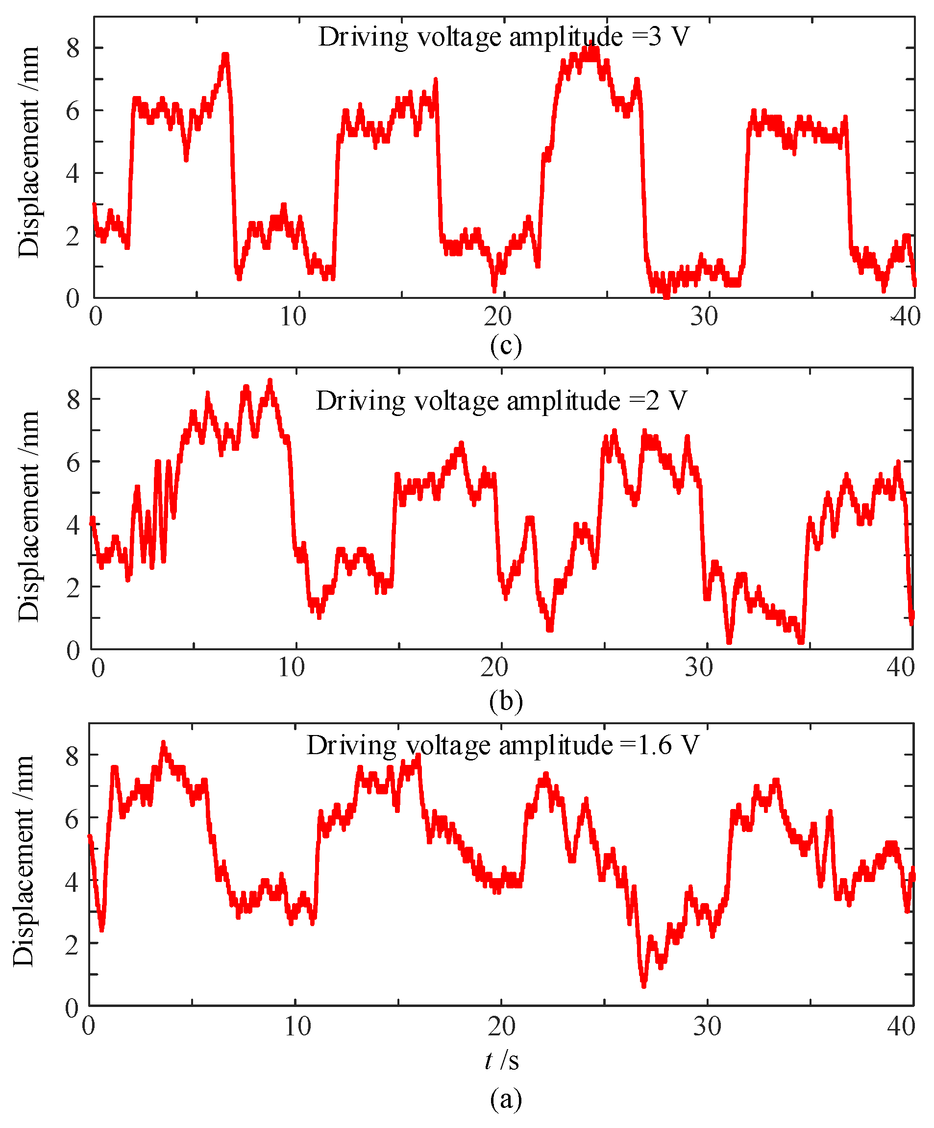
As described in Section 2, there are two operation modes of the proposed actuator: stick-slip mode and scan mode. As the described operation principle of the actuator, in stick-slip mode, the actuator is driven by the mode of the piezoelectric stack’s fast stretch and slow shrink, or slow stretch and fast shrink, which is used to achieve continuous motion over a long distance; in scan mode, the actuator is driven by slowly elongating the piezoelectric stack, which is used to achieve high precision motion within a small displacement. Therefore, the resolution test was carried out to study the minimum displacement output of the stage operated in scan mode. Here, the square wave signal was selected as the driving signal to measure the resolution. To clearly observe the movement of the stage, the period of the square wave was set to 10 s. The voltage amplitude of the drive signal started from 0 V and increased at intervals of 0.2 V. The results show that the displacement response of the stage exhibited a discernible square waveform until the voltage value reached 1.6 V (see Figure 12a); however, the displacement resolution was difficult to predict. When the driving voltage was 2 V, the displacement resolution of 4 nm could be recognized (see Figure 12b). When the voltage reached 3 V, the displacement curve was mostly like the square waveform with a resolution of 5 nm (see Figure 12c).
5. Conclusions
This paper presents a piezoelectric actuator based on stick-slip and scan operation principles for the application of the linear motion stage. Herein, the notable features of the actuator are the flexible hinges, including the composite hinge, pre-pressure adjustment flexible hinge, and transmission flexible hinge, which are designed for decoupling the motion in the action direction of the piezoelectric stack and the direction in which the pre-pressure is applied. Moreover, the use of two kinds of operation modes, stick-slip mode and scan mode, realizes the function of a continuous long-distance motion and high precision motion within a small distance. Finally, a prototype was fabricated, and the performances of the stage were demonstrated. To improve the response performance of the actuator, the driving circuit with a discharge loop was utilized to drive the actuator. Under the sawtooth wave driving signal with an amplitude of 60 V, the forward speed of the stage reached its maximum of 2.5 mm/s at 2.2 kHz, and the backward speed reached its maximum of 1.8 mm/s at 1.4 kHz. In stick-slip mode, when the actuator was driven by a signal train of 0.01 s (driving signal cycle number is 1 and voltage amplitude is 2.2 V) for a driving period of 5.1 s, the finest resolution of the stage achieved 12 nm. In scan mode, to clearly observe the movement of the stage, a square wave signal with a period of 10 s was selected as the driving signal to measure the resolution. The displacement response of the stage exhibited a discernible square waveform until the voltage value reached 1.6 V. A displacement resolution of 4 nm could be recognized when the driving voltage was 2 V, and the displacement curve was mostly like the square waveform with a resolution of 5 nm when the driving voltage reached 3 V.
Author Contributions
Conceptualization, Y.S.; methodology, C.L. and Y.S.; software, C.L.; validation, Y.S. and C.L.; formal analysis, Y.S. and C.L.; resources, Y.S.; writing—original draft preparation, Y.S.; writing—review and editing, Y.S. and J.Z.; visualization, C.L. and J.Z.; supervision, Y.S.; project administration, Y.S.; funding acquisition, Y.S. All authors have read and agreed to the published version of the manuscript.
Funding
This research was funded by the National Natural Science Foundation of China, grant number 51975282.
Institutional Review Board Statement
Not applicable.
Informed Consent Statement
Not applicable.
Data Availability Statement
Not applicable.
Acknowledgments
The authors would like to thank Yuyang Lin, Haichao Sun for their assistance in the actuator test.
Conflicts of Interest
The authors declare no conflict of interest.
References
- Mohith, S.; Upadhya, A.R.; Karanth, N.; Kulkarni, S.M.; Rao, M. Recent trends in piezoelectric actuators for precision motion and their applications: A review. Smart Mater. Struct. 2021, 30, 013002. [Google Scholar] [CrossRef]
- Zhao, C.S. Ultrasonic Motors Technologies and Applications; Springer: Berlin/Heidelberg, Germany, 2011; pp. 1–10. [Google Scholar] [CrossRef]
- Ouyang, P.R.; Tjiptoprodjo, R.C.; Zhang, W.J.; Yang, G.S. Micro-motion devices technology: The state of arts review. Int. J. Adv. Manuf. Technol. 2008, 38, 463–478. [Google Scholar] [CrossRef]
- Silvestri, M.; Confalonieri, M.; Ferrario, A. Piezoelectric Actuators for Micro Positioning Stages in Automated Machines: Experimental Characterization of Open Loop Implementations. FME Trans. 2017, 45, 331. [Google Scholar] [CrossRef] [Green Version]
- Gao, X.; Yang, J.; Wu, J.; Xin, X.; Li, Z.; Yuan, X.; Shen, X.; Dong, S. Piezoelectric Actuators and Motors: Materials, Designs, and Applications. Adv. Mater. Technol. 2020, 5, 1900716. [Google Scholar] [CrossRef]
- Kiziroglou, M.E.; Temelkuran, B.; Yeatman, E.M.; Yang, G.Z. Micro Motion Amplification—A Review. IEEE Access 2020, 8, 64037–64055. [Google Scholar] [CrossRef]
- Rudy, R.Q.; Smith, G.L.; DeVoe, D.L.; Polcawich, R.G. Millimeter-scale traveling wave rotary ultrasonic motors. J. Microelectromech. Syst. 2015, 24, 108–114. [Google Scholar] [CrossRef]
- Kühne, M.; Rochín, R.G.; Cos, R.S.; Astorga, G.J.R.; Peer, A. Modeling and two-input sliding mode control of rotary traveling wave ultrasonic motors. IEEE Trans. Ind. Electron. 2018, 65, 7149–7159. [Google Scholar] [CrossRef] [Green Version]
- Hareesh, P.; DeVoe, D.L. Miniature bulk PZT traveling wave ultrasonic motors for low-speed high-torque rotary actuation. J. Microelectromech. Syst. 2018, 27, 547–554. [Google Scholar] [CrossRef] [PubMed]
- Wang, L.; Wielert, T.; Twiefel, J.; Jin, J.; Wallaschek, J. A rod type linear ultrasonic motor utilizing longitudinal traveling waves: Proof of concept. Smart Mater. Struct. 2017, 26, 085013. [Google Scholar] [CrossRef]
- Le, A.Y.; Mills, J.K.; Benhabib, B. Improved linear ultrasonic motor performance with square-wave based driving-tip trajectory. Smart Mater. Struct. 2015, 24, 037003. [Google Scholar] [CrossRef]
- Yue, J.; Zhiyuan, Y.; Bailiang, Z.; Zhen, L. A novel Π-type linear ultrasonic motor driven by a single mode. Rev. Sci. Instrum. 2018, 89, 125010. [Google Scholar] [CrossRef]
- Yin, Z.; Dai, C.; Cao, Z.; Li, W.; Li, C. Modal analysis and moving performance of a single-mode linear ultrasonic motor. Ultrasonics 2020, 108, 106216. [Google Scholar] [CrossRef] [PubMed]
- Izuhara, S.; Mashimo, T. Linear Piezoelectric Motor Using a Hollow Rectangular Stator. Sens. Actuator A Phys. 2020, 309, 112002. [Google Scholar] [CrossRef]
- Xin, X.; Gao, X.; Wu, J.; Li, Z.; Chu, Z.; Dong, S. A ring-shaped, linear piezoelectric ultrasonic motor operating in E-01mode. Appl. Phys. Lett. 2020, 116, 152902. [Google Scholar] [CrossRef] [Green Version]
- Modler, N.; Winkler, A.; Filippatos, A.; Lovasz, E.-C.; Mărgineanu, D. Simulation and experimental investigation of active lightweight compliant mechanisms with integrated piezoceramic actuators. Smart Mater. Struct. 2016, 25, 085047. [Google Scholar] [CrossRef]
- Bharti, S.; Frecker, M.I. Optimal design and experimental characterization of a compliant mechanism piezoelectric actuator for inertially stabilized rifle. J. Intell. Mater. Syst. Struct. 2004, 15, 93–106. [Google Scholar] [CrossRef]
- Sun, X.; Chen, W.; Zhang, J.; Zhou, R.; Chen, W. A novel piezo-driven linear-rotary inchworm actuator. Sens. Actuators A Phys. 2015, 224, 78–86. [Google Scholar] [CrossRef]
- Mohammad, T.; Mohammad, S. A novel high performance integrated two-axis inchworm piezoelectric motor. Smart Mater. Struct. 2020, 29, 015034. [Google Scholar] [CrossRef]
- Gao, Y.; Wen, J.; Ma, J.; Zhang, Y.; Wang, R.; Hu, Y.; Li, J. A self-adapting linear inchworm piezoelectric actuator based on a permanent magnets clamping structure. Mech. Syst. Signal Process. 2019, 132, 429–440. [Google Scholar] [CrossRef]
- Ma, L.; Jiang, C.; Xiao, J.; Wang, K. Design and analysis of a piezoelectric inchworm actuator. J. Micro-Bio Robot. 2014, 9, 11–21. [Google Scholar] [CrossRef]
- Neuman, J.; Nováček, Z.; Pavera, M.; Zlamal, J.; Kalousek, R.; Spousta, J.; Dittrichova, L.; Sikola, T. Experimental optimization of power-function-shaped drive pulse for stick-slip piezo actuators. Precis. Eng. 2015, 42, 187–194. [Google Scholar] [CrossRef]
- Guo, Z.; Tian, Y.; Zhang, D.; Wang, T.; Wu, M. A novel stick-slip based linear actuator using bi-directional motion of micro positioner. Mech. Syst. Signal Process. 2019, 128, 37–49. [Google Scholar] [CrossRef] [Green Version]
- Qin, F.; Huang, H.; Wang, J.; Tian, L.; Liang, T.; Zhao, H. Design and stepping characteristics of novel stick-slip piezo-driven linear actuator. Smart Mater. Struct. 2019, 28, 075026. [Google Scholar] [CrossRef]
- Zhang, Q.S.; Chen, X.B.; Yang, Q.; Zhang, W.J. Development and characterization of a novel piezoelectric driven stick–slip actuator with anisotropic-friction surfaces. Int. J. Adv. Manuf. Technol. 2012, 61, 1029–1034. [Google Scholar] [CrossRef] [Green Version]
- Wang, L.; Chen, D.; Cheng, T.H.; He, P.; Lu, X.H.; Zhao, H.W. A friction regulation hybrid driving method for backward motion restraint of the smooth impact drive mechanism. Smart Mater. Struct. 2016, 25, 085033. [Google Scholar] [CrossRef]
- Cheng, T.; Li, H.; He, M.; Zhao, H.; Lu, X.; Gao, H. Investigation on driving characteristics of a piezoelectric stick–slip actuator based on resonant/off-resonant hybrid excitation. Smart Mater. Struct. 2017, 26, 035042. [Google Scholar] [CrossRef]
- Jin, J.; Shi, Y.; Li, Y.; Zhao, C. Research on novel inertial linear ultrasonic piezoelectric motor. Opt. Precis. Eng. 2008, 16, 2371–2377. (In Chinese) [Google Scholar]
Figure 1.
Construction of the piezoelectric actuator.

Figure 2.
Configuration of the stage. (a) Structural explosion diagram of the stage. (b) Side view of the stage.
Figure 2.
Configuration of the stage. (a) Structural explosion diagram of the stage. (b) Side view of the stage.

Figure 3.
Operation principle of the actuator. (a) Ready state. (b) Stick phase. (c) Slip phase. (d) Scan mode.
Figure 3.
Operation principle of the actuator. (a) Ready state. (b) Stick phase. (c) Slip phase. (d) Scan mode.

Figure 4.
Finite element model of the actuator.

Figure 5.
Influence of the composite flexible hinge thickness on (a) output displacement of the actuator and (b) vertical displacement of the inertial mass block.
Figure 5.
Influence of the composite flexible hinge thickness on (a) output displacement of the actuator and (b) vertical displacement of the inertial mass block.

Figure 6.
Model shape and frequency of the actuator elastomer. (a) f = 7376 Hz. (b) f = 9666 Hz. (c) f = 12,440 Hz. (d) f = 12,538 Hz.
Figure 6.
Model shape and frequency of the actuator elastomer. (a) f = 7376 Hz. (b) f = 9666 Hz. (c) f = 12,440 Hz. (d) f = 12,538 Hz.

Figure 7.
Stiffness calculation of the transmission flexible hinge. (a) Schematic diagram of applying force. (b) Deformation displacement diagram.
Figure 7.
Stiffness calculation of the transmission flexible hinge. (a) Schematic diagram of applying force. (b) Deformation displacement diagram.

Figure 8.
Prototype of the stage and its measurement setup. (a) Prototype of the stage. (b) Measurement setup.
Figure 8.
Prototype of the stage and its measurement setup. (a) Prototype of the stage. (b) Measurement setup.

Figure 9.
Running test of the stage.

Figure 10.
Speed vs. frequency.

Figure 11.
Step characteristics of the stage. (a) Driving signal cycle number is 10. (b) Driving signal cycle number is 1.
Figure 11.
Step characteristics of the stage. (a) Driving signal cycle number is 10. (b) Driving signal cycle number is 1.

Figure 12.
Resolution characteristics of the stage in scan operation mode. (a)Driving voltage amplitude is 1.6 V. (b) Driving voltage amplitude is 2 V. (c) Driving voltage amplitude is 3 V.
Figure 12.
Resolution characteristics of the stage in scan operation mode. (a)Driving voltage amplitude is 1.6 V. (b) Driving voltage amplitude is 2 V. (c) Driving voltage amplitude is 3 V.

Publisher’s Note: MDPI stays neutral with regard to jurisdictional claims in published maps and institutional affiliations. |
© 2021 by the authors. Licensee MDPI, Basel, Switzerland. This article is an open access article distributed under the terms and conditions of the Creative Commons Attribution (CC BY) license (http://creativecommons.org/licenses/by/4.0/).
Share and Cite
MDPI and ACS Style
Shi, Y.; Lou, C.; Zhang, J. Investigation on a Linear Piezoelectric Actuator Based on Stick-Slip/Scan Excitation. Actuators 2021, 10, 39. https://0-doi-org.brum.beds.ac.uk/10.3390/act10020039
AMA Style
Shi Y, Lou C, Zhang J. Investigation on a Linear Piezoelectric Actuator Based on Stick-Slip/Scan Excitation. Actuators. 2021; 10(2):39. https://0-doi-org.brum.beds.ac.uk/10.3390/act10020039
Chicago/Turabian StyleShi, Yunlai, Chengshu Lou, and Jun Zhang. 2021. "Investigation on a Linear Piezoelectric Actuator Based on Stick-Slip/Scan Excitation" Actuators 10, no. 2: 39. https://0-doi-org.brum.beds.ac.uk/10.3390/act10020039
Note that from the first issue of 2016, this journal uses article numbers instead of page numbers. See further details here.