
An ARX Model-Based Predictive Control of a Semi-Active Vehicle Suspension to Improve Passenger Comfort and Road-Holding

 , , , and
Abstract
:1. Introduction
2. One-Quarter Semi-Active Suspension, Including the Actuator’s Dynamics
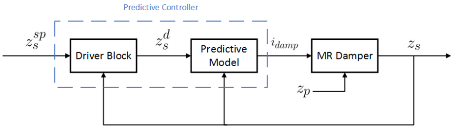
3. Predictive Control Based on an ARX Model
3.1. Driver Block
3.2. Predictive Model
4. Performance Criteria
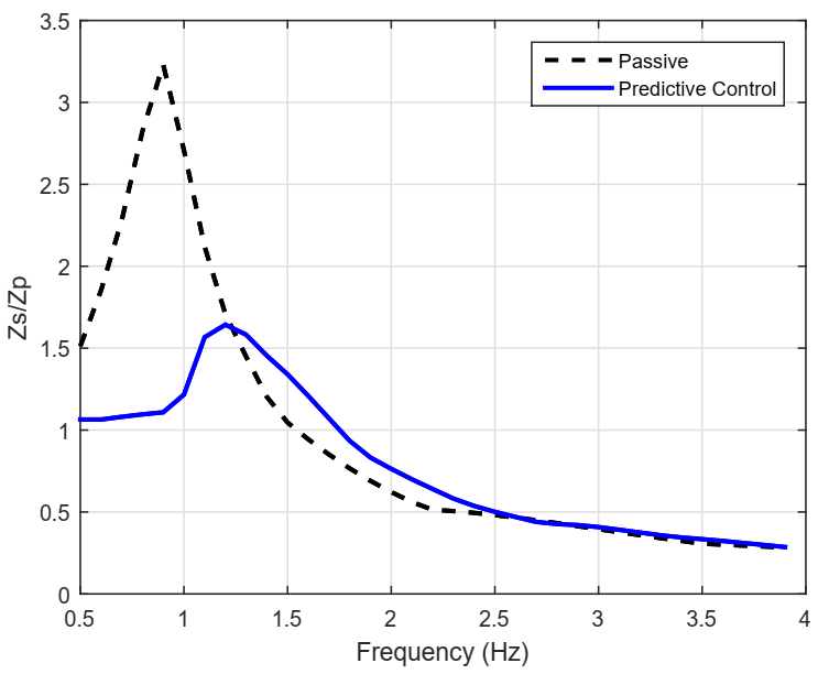
- Passenger comfort in low frequencies.Below 5 Hz, keep the relation gain between the sprung mass displacement and the road profile, i.e., () less than 2. The aim is to decrease the maximum peak (around 1 Hz for an average city vehicle). For this criterion, is a sinusoidal signal defined by m.
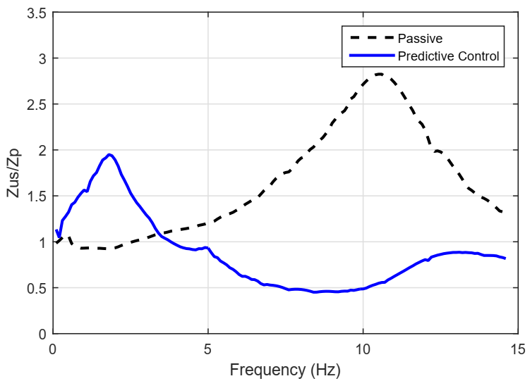
- Vehicle stability between 0 and 15 Hz.Measured through the division of the relation (), i.e., unsprung mass displacement over the road profile. The goal is to cut down the maximum peak observed in the range [10–13] Hz, for an average city vehicle. For this test, is represented by m.
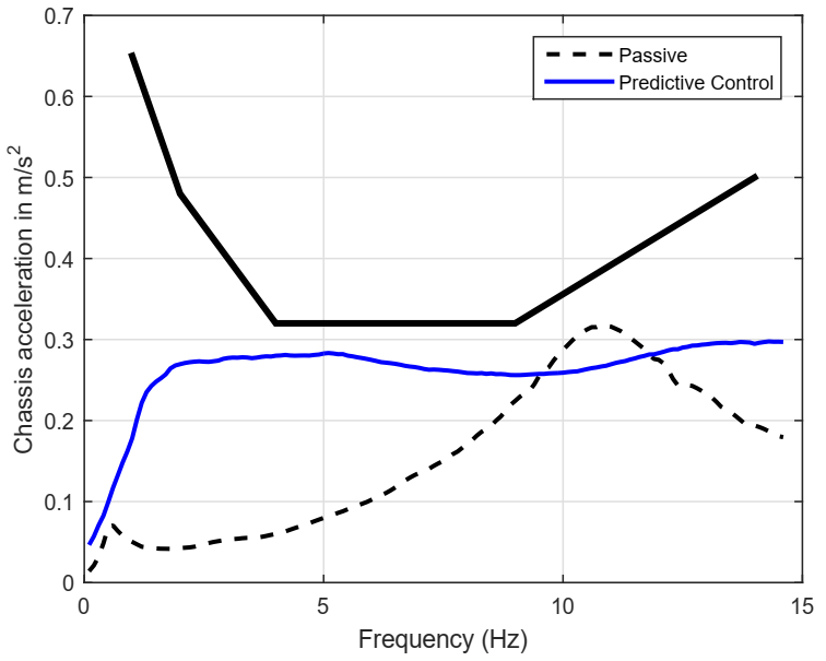
- Passenger Comfort; the acceleration criterion.From 4 to 30 Hz, keep the root mean square acceleration (rms) of the sprung mass (one quarter of the chassis), below the maximum rms vertical acceleration limit developed by the International Standard ISO 2631 as explained in [2], to assure passenger comfort for up to 8 h. To run this test, apply the as in vehicle stability.
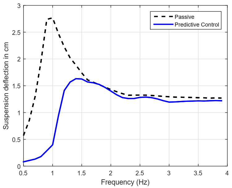
- Suspension Deflection.From 0 to 4 Hz, keep () within the physical limits of shock absorber to avoid unmodeled dynamics and a premature suspension wear-off. The herein employed MR damper has cm as displacement physical limits, as explained in [47]. For this test, is the same defined for passenger comfort in low frequencies.
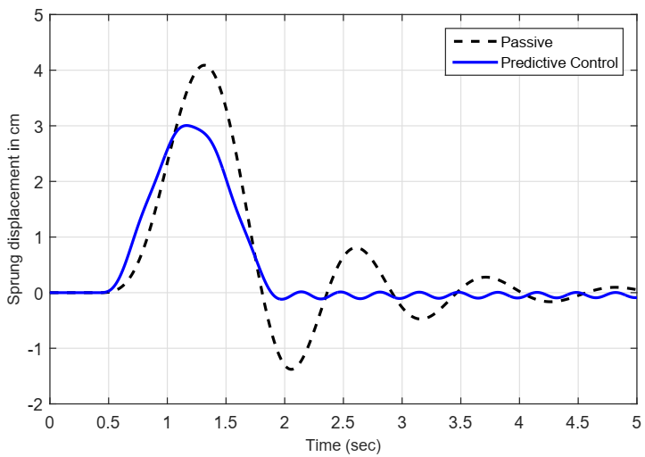
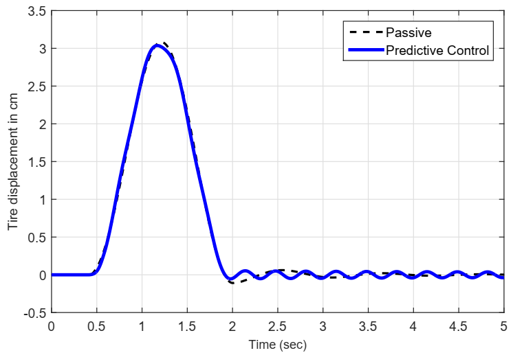
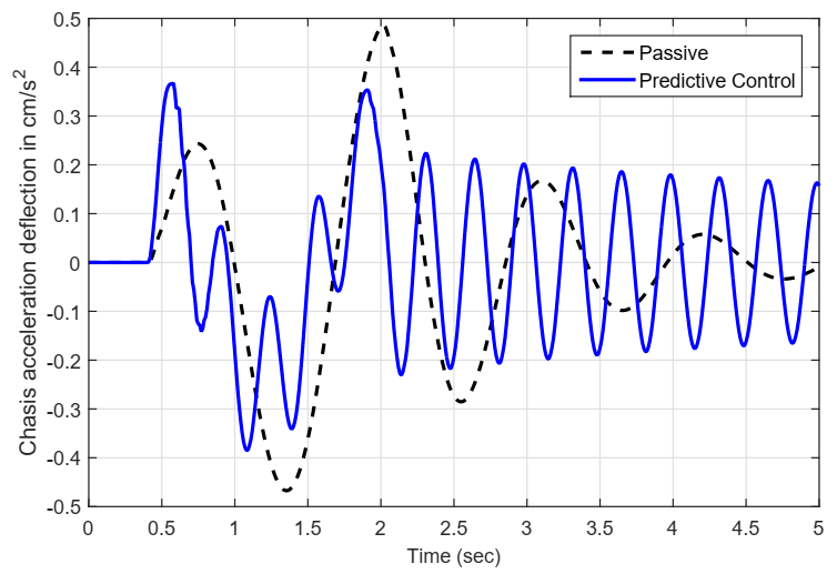
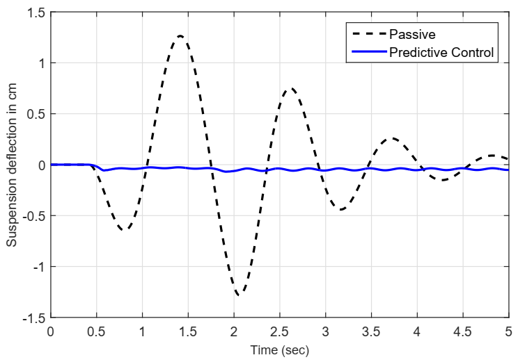
- Performance in time domain.With representing a road bump profile; the objective is to decrease, as much as possible, overshoot, undershoot and settling time for: (), (), rms of , and (). The degree of improvement is measured with respect to passive suspension.
5. Results and Discussion
5.1. Simulation Work
5.2. Predictive Controller Design
5.3. Results in the Frequency Domain
5.4. Results in Time Domain
6. Conclusions and Future Work
Author Contributions
Funding
Institutional Review Board Statement
Informed Consent Statement
Data Availability Statement
Acknowledgments
Conflicts of Interest
Abbreviations
| ARX | AutoRegressive with eXogenous input |
| DOF | Degrees of Freedom |
| LPV | Linear Parameter-Varying control |
| MPC | Model Predictive Control |
| MR | Magneto-Rheological |
References
- Milliken, W.; Douglas, M. Race Car Vehicle Dynamics; Society of Automotive Engineers, Inc.: Warrendale, PA, USA, 1995. [Google Scholar]
- Wong, J.Y. Theory of Ground Vehicles, 3rd ed.; John Wiley and Sons, Inc.: New York, NY, USA, 2001. [Google Scholar]
- Gillespie, T. Fundamentals of Vehicle Dynamics; Society of Automotive Engineers, Inc.: Warrendale, PA, USA, 1992. [Google Scholar]
- Goncalves, F. Dynamic Analysis of Semi-Active Control Techniques for Vehicle Applications. Master’s Thesis, Virginia Polytechnic Institute and State University, Blacksburg, VA, USA, 2001. [Google Scholar]
- Pauwelussen, J.P.; Pacejka, H.B. Smart Vehicles; Sweets and Zeitlinger Publishers: Lisse, The Netherlands, 1995. [Google Scholar]
- Guglielmino, E.; Sireteanu, T.; Stammers, C.; Ghita, G.; Giuclea, M.M. Semi-Active Suspension CONTROL, Improved Vehicle Ride and Road Friendliness; Springer: London, UK, 2008. [Google Scholar]
- Butz, T.; Von Stryk, O. Modelling and Simulation of Electro- and Magnetorheological Fluid Dampers. ZAMM J. Appl. Math. Mech. 2002, 82, 3–20. [Google Scholar] [CrossRef]
- Spencer, B.F., Jr.; Dyke, S.; Sain, M.; Carlson, J. Phenomenological Model of a Magnetorheological Damper. ASCE J. Eng. Mech. 1997, 123, 230–238. [Google Scholar] [CrossRef]
- Stanway, R. The development of force actuators using ER and MR fluid technology. In Proceedings of the IEEE Colloquium on Actuator Technology: Current Practice and New Developments, London, UK, 10 May 1996; pp. 6/1–6/5. [Google Scholar]
- Carlson, J.D.; Catanzarite, D.M.; St. Clair, K.A. Commercial Magneto-rheological Fluid Devices. Int. J. Mod. Phys. B 1996, 10, 2857–2865. [Google Scholar] [CrossRef]
- Chung, S.; Shin, H.-B. High-Voltage Power Supply for Semi-Active Suspension System with ER-Fluid Damper. IEEE Trans. Veh. Technol. 2004, 53, 206–211. [Google Scholar] [CrossRef]
- Wen, Y.-K. Method for Random Vibration of Hysteretic Systems. ASCE J. Eng. Mech. Div. 1976, 102, 249–263. [Google Scholar] [CrossRef]
- Ambhore, N.; Hivarale, S.; Pangavhane, D.R. A Study of Bouc-Wen Model of Magnetorheological Fluid Damper for Vibration Control. Int. J. Eng. Res. Technol. 2013, 2, 1–6. [Google Scholar]
- Razman, M.A.; Priyandoko, G.; Yusoff, A.R. Bouc-Wen Model Parameter Identification for a MR Fluid Damper Using Particle Swarm Optimization. Adv. Mater. Res. 2014, 903, 279–284. [Google Scholar] [CrossRef]
- Zhu, W.; Rui, X.-T. Semi-active Vibration Control Using a Magnetorheological Damper and a Magnetorheological Elastomer Based on the Bouc-Wen Model. Shock Vib. 2014, 2014, 1–10. [Google Scholar]
- Xie, H.L.; Liu, Z.B.; Yang, J.Y.; Sheng, Z.Q.; Xu, Z.W. Modelling of Magnetorheological Damper for Intelligent Bionic Leg and Simulation of Knee Joint Movement Control. Int. J. Simul. Model. 2016, 15, 144–156. [Google Scholar] [CrossRef]
- Félix-Herrán, L.; Mehdi, D.; Soto, R.; de J Rodríguez-Ortiz, J.; Ramírez-Mendoza, R. Control of a Semi-active Suspension with a Magnetorheological Damper Modelled via Takagi-Sugeno. In Proceedings of the 18th Mediterranean Conference on Control & Automation, Marrakech, Morocco, 23–25 June 2010; pp. 1265–1270. [Google Scholar]
- Félix-Herrán, L.C.; Mehdi, D.; de J Rodríguez-Ortiz, J.; Soto, R.; Ramírez-Mendoza, R. H∞ control of a suspension with a magnetorheological damper. Int. J. Control 2012, 85, 1026–1038. [Google Scholar] [CrossRef]
- Yang, G.Q.; Zhao, Y.Q. Fuzzy Control of Vehicle Suspension System. Adv. Mater. Res. 2012, 383–390, 2012–2017. [Google Scholar] [CrossRef]
- Kurczyk, S.; Pawelczyk, M. Fuzzy Control for Semi-Active Vehicle Suspension. J. Low Freq. Noise Vib. Act. Control 2013, 32, 217–226. [Google Scholar] [CrossRef] [Green Version]
- Félix-Herrán, L.C.; Mehdi, D.; Ramírez-Mendoza, R.; de J Rodríguez-Ortiz, J.; Soto, R. H2 control of a one-quarter semi-active ground vehicle suspension. J. Appl. Res. Technol. 2016, 14, 173–183. [Google Scholar] [CrossRef] [Green Version]
- Xue, W.; Li, K.; Chen, Q.; Liu, G. Mixed FTS H∞ control of vehicle active suspensions with shock road disturbance. Veh. Syst. Dyn. 2018, 57, 841–854. [Google Scholar] [CrossRef]
- Erol, B.; Oz, M.A.; Ucun, L. Two-degree-of-freedom compensator design for disturbance attenuation problem via higher order sinusoidal input describing functions theory. Trans. Inst. Meas. Control 2019, 1–10. [Google Scholar] [CrossRef]
- Wang, G.; Chen, C.; Yu, S. Finite-time sliding mode tracking control for active suspension systems via extended super-twisting observer. Proc. Inst. Mech. Eng. Part I J. Syst. Control. Eng. 2017, 231, 459–470. [Google Scholar] [CrossRef]
- Qin, W.; Shangguan, W.-B.; Yin, Z. Sliding mode control of double-wishbone active suspension systems based on equivalent 2-degree-of-freedom model. Proc. Inst. Mech. Eng. Part D J. Automob. Eng. 2020, 234, 3164–3179. [Google Scholar] [CrossRef]
- De J Lozoya Santos, J.; Tudon-Martinez, J.C.; Ramirez-Mendoza, R.A. LPV Control for a Semi-Active Suspension Quarter of Car-One Parameter Case. In Proceedings of the MATEC Web of Conferences 81, Lucerne, Switzerland, 6–10 July 2016; pp. 1–4. [Google Scholar]
- Tudón-Martínez, J.C.; Varrier, S.; Morales-Menendez, R.; Sename, O. Fault Tolerant Control in a Semi-Active Automotive Suspension (Control Tolerante a Fallas en una Suspensión Automotriz Semi-Activa). RIAI Rev. Iberoam. Autom. Inform. Ind. 2016, 13, 56–66. (In Spanish) [Google Scholar] [CrossRef] [Green Version]
- Rao, K.D.; Kumar, S. Modeling and Simulation of Quarter Car Semi Active Suspension System Using LQR Controller. In Proceedings of the 3rd International Conference on Frontiers of Intelligent Computing: Theory and Applications (FICTA). Advances in Intelligent Systems and Computing, Bhubaneswar, Odisha, India, 14–15 November 2014; pp. 441–448. [Google Scholar]
- Beltran-Carbajal, F.; Valderrabano-Gonzalez, A.; Favela-Contreras, A.; Hernandez-Avila, J.L.; Lopez-Garcia, I.; Tapia-Olvera, R. An Active Vehicle Suspension Control Approach with Electromagnetic and Hydraulic Actuators. Actuators 2019, 8, 35. [Google Scholar] [CrossRef] [Green Version]
- Zapateiro, M.; Pozo, F.; Karimi, H.R.; Luo, N. Semi-active Control Methodologies for Suspension Control With Magnetorheological Dampers. IEEE/ASME Trans. Mechatronics 2012, 17, 370–380. [Google Scholar] [CrossRef] [Green Version]
- Krauze, P.; Kasprzyk, J. Vibration control in quarter-car model with magnetorheological dampers using FxLMS algorithm with preview. In Proceedings of the 2014 European Control Conference (ECC), Strasbourg, France, 24–27 June 2014; pp. 1005–1010. [Google Scholar]
- Wu, J.-L. A Simultaneous Mixed LQR /H∞ Control Approach to the Design of Reliable Active Suspension Controllers. Asian J. Control 2014, 19, 415–427. [Google Scholar] [CrossRef]
- Olurotimi, A.D.; Jimoh, O.P. Neural Network-Based Identification and Approximate Predictive Control of a Servo-Hydraulic Vehicle Suspension System. Eng. Lett. 2010, 18. [Google Scholar]
- Sehr, M.A.; Bitmead, R.R. Stochastic output-feedback model predictive control. Automatica 2018, 94, 315–323. [Google Scholar] [CrossRef]
- Cho, B.K. Active Suspension Controller Design Using MPC with Preview Information. KSME Int. J. 1999, 13, 168–174. [Google Scholar] [CrossRef]
- Çalışkan, K.; Henze, R.; Küçükay, F. Potential of Road Preview for Suspension Control under Transient Road Inputs. IFAC-PapersOnLine 2016, 49, 117–122. [Google Scholar] [CrossRef]
- Shao, S.; Zhou, H.; Liu, H. Distributed Model Predictive Control and Implementation for Vehicle Active Suspensions. IFAC-PapersOnLine 2018, 51, 961–966. [Google Scholar] [CrossRef]
- Hu, Y.; Chen, M.Z.Q.; Hou, Z. Multiplexed model predictive control for active vehicle suspensions. Int. J. Control 2014, 88, 347–363. [Google Scholar] [CrossRef]
- Canale, M.; Milanese, M.; Novara, C. Semi-Active Suspension Control Using “Fast” Model-Predictive Techniques. IEEE Trans. Control. Syst. Technol. 2006, 14, 1034–1046. [Google Scholar] [CrossRef] [Green Version]
- Houzhong, Z.; Jiasheng, L.; Chaochun, Y.; Xiaoqiang, S.; Yingfeng, C. Application of explicit model predictive control to a vehicle semi-active suspension system. J. Low Freq. Noise, Vib. Act. Control 2020, 39, 772–786. [Google Scholar] [CrossRef]
- Giorgetti, N.; Bemporad, A.; Tseng, H.E.; Hrovat, D. Hybrid model predictive control application towards optimal semi-active suspension. Int. J. Control 2006, 79, 521–533. [Google Scholar] [CrossRef]
- Morato, M.M.; Sename, O.; Dugard, L. LPV-MPC Fault Tolerant Control of Automotive Suspension Dampers. IFAC-PapersOnLine 2018, 51, 31–36. [Google Scholar] [CrossRef]
- Guanetti, J.; Borrelli, F. Stochastic MPC for cloud-aided suspension control. In Proceedings of the 2017 IEEE 56th Annual Conference on Decision and Control (CDC), Melbourne, Australia, 12–15 December 2017; pp. 238–243. [Google Scholar]
- Wu, J.; Wang, Z.; Zhang, L. Unbiased-estimation-based and computation-efficient adaptive MPC for four-wheel-independently-actuated electric vehicles. Mech. Mach. Theory 2020, 154, 1–15. [Google Scholar] [CrossRef]
- Enders, E.; Burkhard, G.; Munzinger, N. Analysis of the Influence of Suspension Actuator Limitations on Ride Comfort in Passenger Cars Using Model Predictive Control. Actuators 2020, 9, 77. [Google Scholar] [CrossRef]
- Félix-Herrán, L.C.; Soto, R.; de J Rodríguez-Ortiz, J.; Ramirez-Mendoza, R.A. Fuzzy Control for a Semi-Active Vehicle Suspension with a Magnetorheological Damper. In Proceedings of the European Control Conference, Budapest, Hungary, 23–26 August 2009; pp. 4398–4403. [Google Scholar]
- Sireteanu, T.; Stancioiu, D.; Stammers, C.W. Modelling of magnetorheological fluid dampers. Proc. Rom. Acad. 2001, 2, 105–113. [Google Scholar]
- Martin-Sanchez, J.M. A new solution to adaptive control. Proc. IEEE 1976, 64, 1209–1218. [Google Scholar] [CrossRef]
- Sánchez, M.; Rodellar, J. Adaptive Predictive Control: From the Concepts to Plant Optimization, 6th ed.; Prentice-Hall International Series in Systems and Control Engineering: London, UK, 1996. [Google Scholar]
- Bastow, D.; Howard, G.; Whitehead, J. Car Suspension and Handling; SAE International: New York, NY, USA, 2004. [Google Scholar]
- Poussot-Vassal, C.; Sename, O.; Dugard, L.; Gáspár, P.; Szabó, Z.; Bokor, J. A new semi-active suspension control strategy through LPV technique. J. Control Eng. Pract. 2008, 16, 1519–1534. [Google Scholar] [CrossRef]
- Do, A.; Sename, O.; Dugard, L. An LPV control approach for semi-active suspension control with actuator constraints. In Proceedings of the American Control Conference, Baltimore, MD, USA, 30 June–2 July 2010; pp. 4653–4658. [Google Scholar] [CrossRef] [Green Version]
- Lam, H.F.; Lai, C.Y.; Liao, W.H. Automobile Suspension Systems with MR Fluid Dampers; Technical Report; Department of Mechanical and Automation Engineering, The Chinese University of Hong Kong: Hong Kong, China, 2002. [Google Scholar]


| Step | Description |
|---|---|
| 1 | Get reference |
| 2 | Get process output |
| 3 | Compute , , |
| 4 | Compute |
| 5 | Compute , , |
| 6 | Compute control signal |
| Parameter | Value |
|---|---|
| 450 kg | |
| 45 kg | |
| 16,000 N/m | |
| 210,000 N/m | |
| c | 1000 Ns/m |
| Suspension | () Gain | () Gain | Max () in cm. | |
|---|---|---|---|---|
| Passive | 3.23 | 2.97 | ✓ | 2.77 × |
| Semi-active Predictive | 1.64 | 1.95 | ✓ | 1.63 ✓ |
Publisher’s Note: MDPI stays neutral with regard to jurisdictional claims in published maps and institutional affiliations. |
© 2021 by the authors. Licensee MDPI, Basel, Switzerland. This article is an open access article distributed under the terms and conditions of the Creative Commons Attribution (CC BY) license (http://creativecommons.org/licenses/by/4.0/).
Share and Cite
Piñón, A.; Favela-Contreras, A.; Félix-Herrán, L.C.; Beltran-Carbajal, F.; Lozoya, C. An ARX Model-Based Predictive Control of a Semi-Active Vehicle Suspension to Improve Passenger Comfort and Road-Holding. Actuators 2021, 10, 47. https://0-doi-org.brum.beds.ac.uk/10.3390/act10030047
Piñón A, Favela-Contreras A, Félix-Herrán LC, Beltran-Carbajal F, Lozoya C. An ARX Model-Based Predictive Control of a Semi-Active Vehicle Suspension to Improve Passenger Comfort and Road-Holding. Actuators. 2021; 10(3):47. https://0-doi-org.brum.beds.ac.uk/10.3390/act10030047
Chicago/Turabian StylePiñón, Alejandro, Antonio Favela-Contreras, Luis C. Félix-Herrán, Francisco Beltran-Carbajal, and Camilo Lozoya. 2021. "An ARX Model-Based Predictive Control of a Semi-Active Vehicle Suspension to Improve Passenger Comfort and Road-Holding" Actuators 10, no. 3: 47. https://0-doi-org.brum.beds.ac.uk/10.3390/act10030047