
A Note on the Electromechanical Design of a Robotic Hummingbird


Department of Control Engineering and System Analysis, Université Libre de Bruxelles (ULB), CP. 165-55, 50 Av. F.D. Roosevelt, B-1050 Brussels, Belgium
*
Author to whom correspondence should be addressed.
†
Current address: Flanders Make, 3001 Leuven, Belgium.
Actuators 2021, 10(3), 52; https://0-doi-org.brum.beds.ac.uk/10.3390/act10030052
Submission received: 25 January 2021
/
Revised: 13 February 2021
/
Accepted: 3 March 2021
/
Published: 7 March 2021
(This article belongs to the Section Actuators for Robotics)
Abstract
:This paper analyzes the lift-production system in hovering of the flapping wing robot COLIBRI of the size of a hummingbird. The paper first examines the flapping wing mechanism for which a new gear transmission is proposed to reduce the friction and facilitate the assembly. Next, a sensitivity analysis is performed on the wing size. Then, the paper discusses several options for the gearbox, various DC motors and two battery configurations (a single battery or two batteries in series) to minimize the heat generation and increase the flight time. The configuration involving two batteries has been found more effective. The flight time is predicted using Shepherd’s discharge model and it is confirmed by an experiment. The robot sustains an endurance of nearly 5 min to produce a lift force equal to the weight of the robot.
1. Introduction
In recent years, several robotic projects have been developed that attempt to mimic the flight of a large hummingbird [1,2,3], with a span and weight around 20 cm and 20 gr. Although far from being as sophisticated as natural hummingbirds, these projects include some of their features: two wings, tailless, active stabilization by manipulating the wing camber; their weight penalty compared with natural hummingbirds of the same size is still significant, but they show clearly the feasibility of a robotic hummingbird in a not-too-distant future, which could open the road to unprecedented flight agility. If one excepts the nano-hummingbird [1] developed by AeroVironment with a generous Darpa funding, these projects have been pursued in an academic environment, using commercial low-cost components (mostly from toys). They result from a long struggle of the researchers with a multidisciplinary problem involving unsteady aerodynamics, aeroelasticity, mechanism and control, and often necessitating to develop dedicated testing devices.
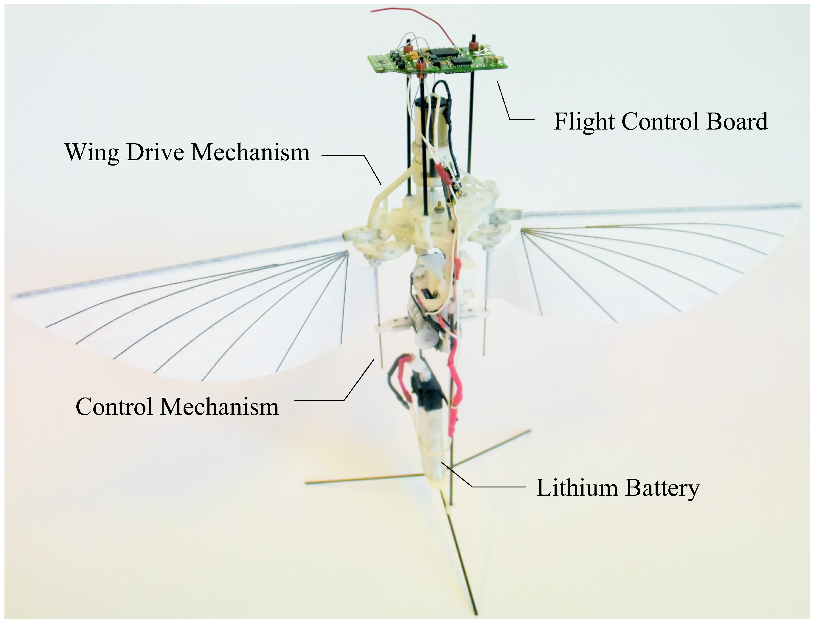
Our project, named COLIBRI (Figure 1) started in 2011 and has been pursued continuously with modest internal funding [3,4,5,6] (the nature of our project failed to attract private or public funding for lack of clearly identified short-term applications). For a video, see [7].
A problem common to all existing projects is the limited flight time, from a few minutes for the nano-hummingbird [1] to less than one minute for the COLIBRI [5], because of overheating of the main motor actuating the flapping mechanism. By comparison, the Black Hornet, a rotorcraft of similar size, has a flight autonomy of 25 min. The main problem is the overweight of the robot. In a recent study, the Konkuk university team succeeded in reducing the weight of their robot to 15.8 gr, allowing the extension of the flight time to almost 9 min [8]. This was achieved by extending the wing area, flapping at lower frequency and using a battery of 3.7 V.
The aim of this paper is to re-analyze the complete lift-production system of the flapping wing robot, i.e., the flapping mechanism, the flapping wing aerodynamics, the gearbox, the DC motor and the battery, and find out how the various subsystems may be combined to achieve the design goals. The paper is organized as follows: Section 2 describes the recent improvements brought to the flapping mechanism to reduce the friction and simplify its construction. Section 3 studies the aerodynamic performance of wings of various sizes and shapes, including trailing edge serration. Section 4 is devoted to the battery; two options are considered: a single battery of 3.7 V and two batteries in series leading to 7.4 V. Section 5 considers several low-cost DC motors. Section 6 combines the four subsystems together and evaluates the performance of various configurations. Section 7 uses the battery discharge curves to evaluate the flight time and reports on an endurance test. Section 8 considers the power-to-lift ratio. The conclusions are given in Section 9.
2. Flapping Mechanism
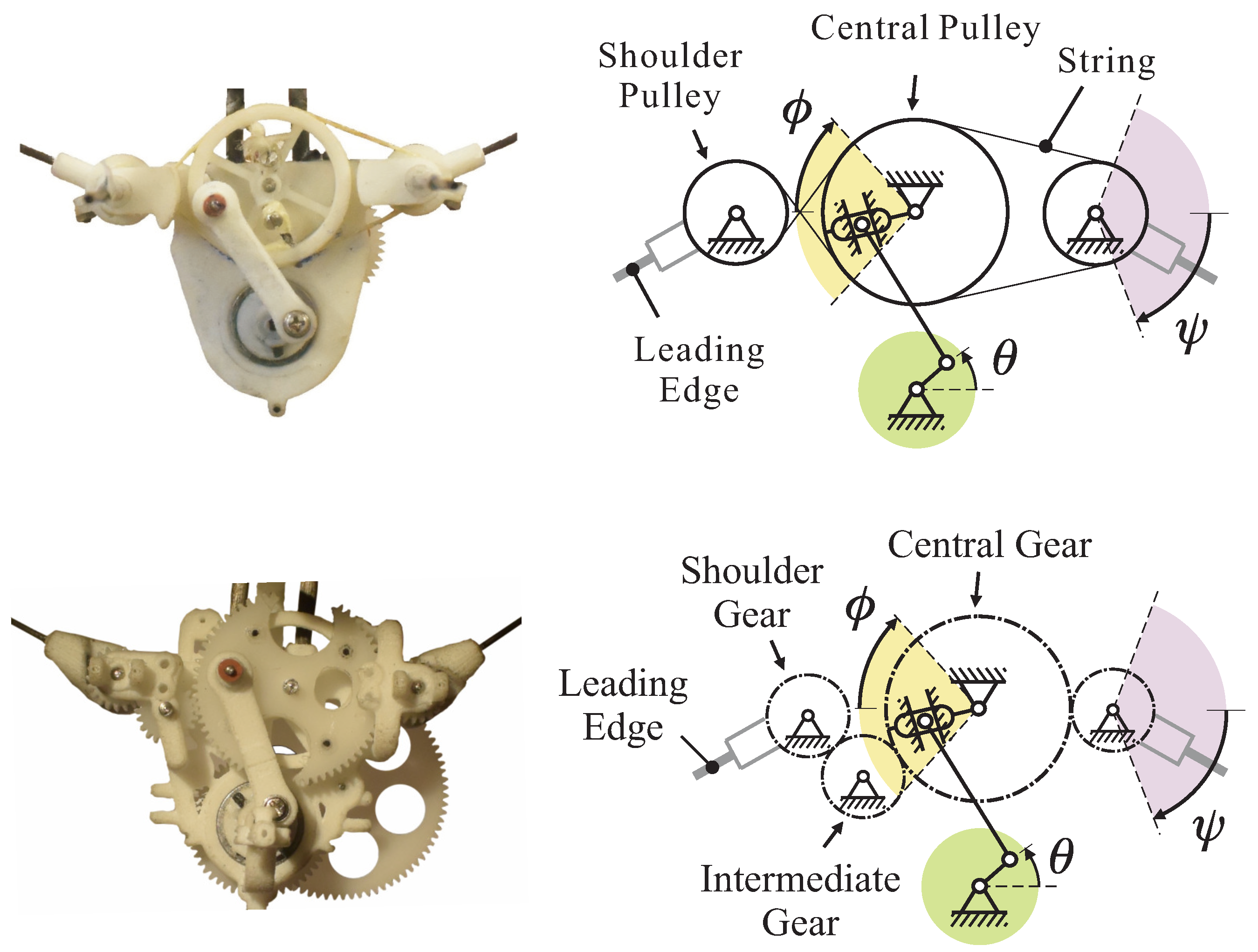
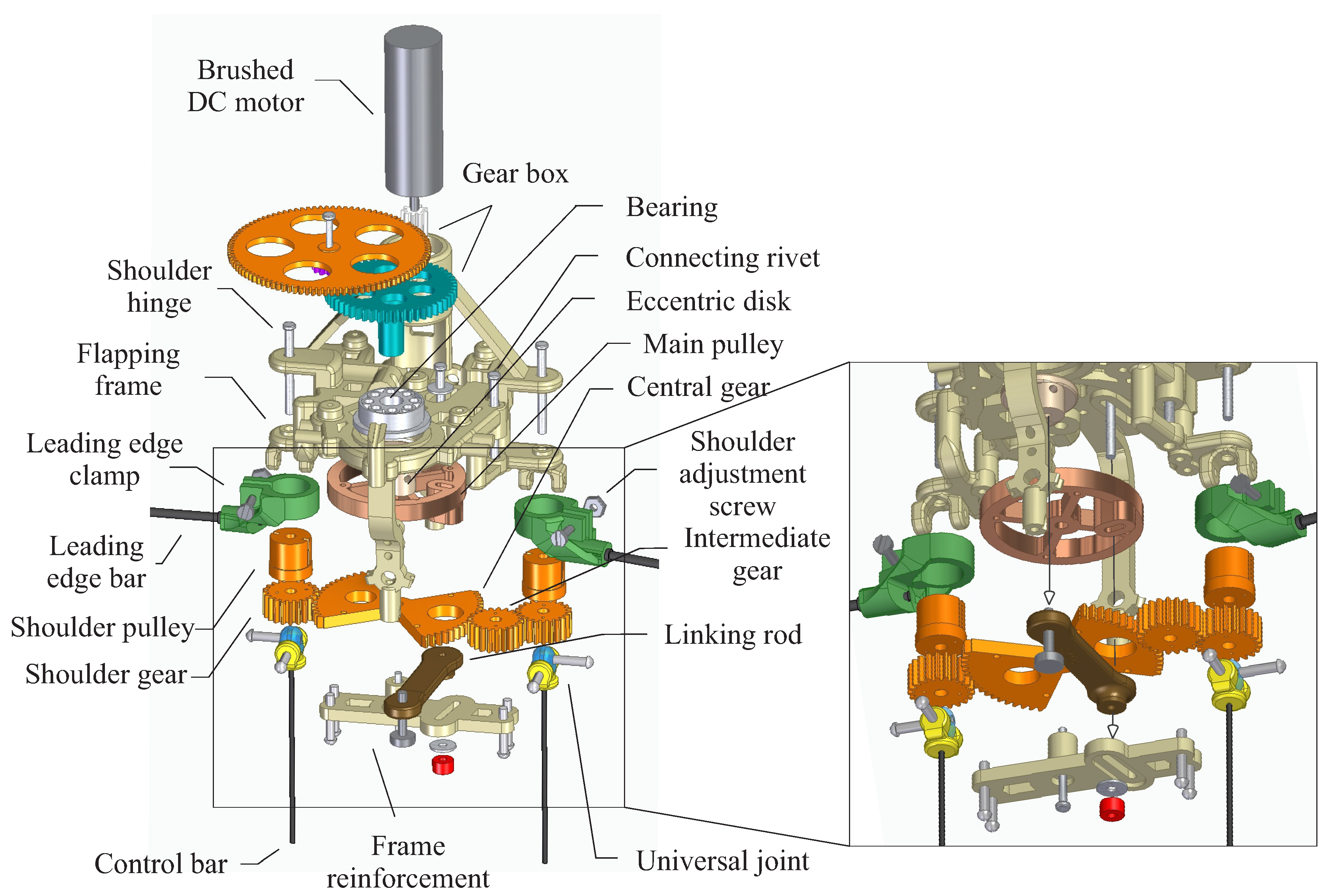
The wings of the COLIBRI robot consist of stiffened membranes attached by two sleeves to the leading-edge bar (for flapping) and to the root edge bar for control [3,6]. The flapping is obtained by rotating the leading-edge bar harmonically in the flapping plane, about the shoulder hinge (there is only one kinematic degree of freedom). The wing drive mechanism transforms the continuous rotation of the gearbox output into the flapping motion . The large flapping amplitude is achieved in two steps: the first stage is a slider crank mechanism which transforms the continuous output of the gearbox, , into a reciprocating motion of moderate amplitude of the central wheel (Figure 2). The second stage amplifies the rotating motion from to the flapping angle . In the previous design, the second stage was implemented with a string transmission, following [9]. However, the string mechanism has a few drawbacks: it is difficult to tune during the assembly, the right and left flapping angles are sensitive to tolerances on the diameter of the shoulder pulley, and the prestresses due to the tension in the string increase the friction in the mechanism. The problems were solved by replacing the string transmission by a gear transmission which, in addition to removing the drawbacks mentioned above, can be easily lubricated; however, it is slightly heavier. Figure 3 shows an exploded view of the flapping mechanism with a gear transmission.
Even though the flapping mechanism has a single degree of freedom, aerodynamic tests reported in [6] showed that the wing aerodynamics is very complex, and the membrane wings exhibit a strong aeroelastic behavior; in particular, the out of plane flexibility of the leading-edge bar plays a significant role. The best performances were achieved with a carbon bar of 0.7 mm.
3. Aerodynamic Performances
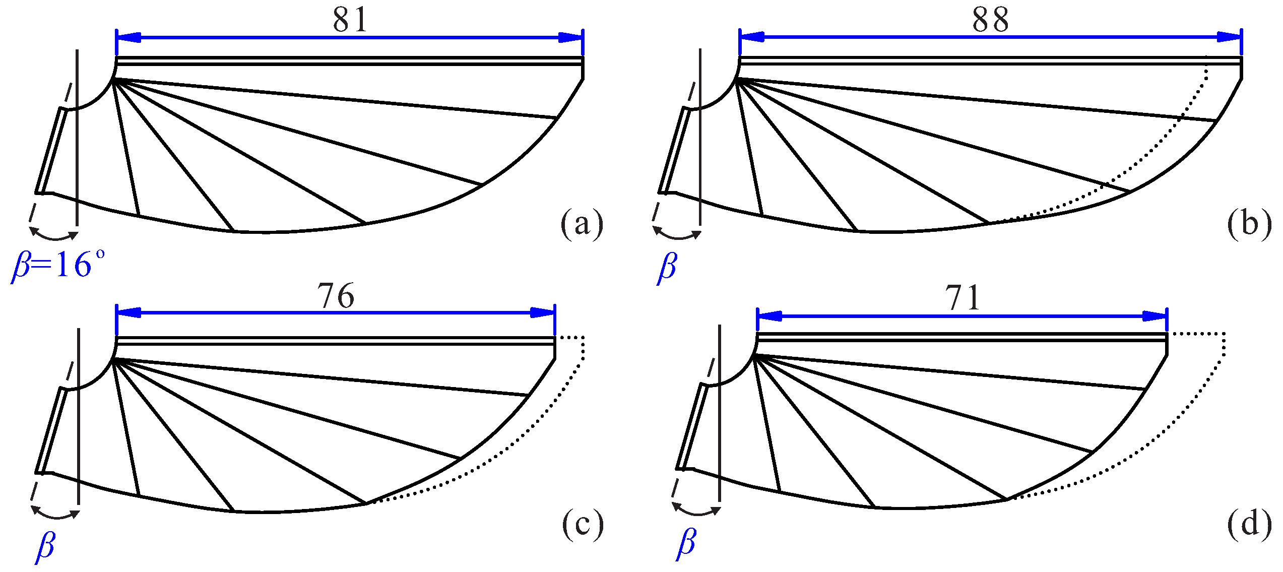
Figure 4 shows a set of wings of various sizes. Figure 4a is the nominal one which has been used earlier in this project (it is the result of extensive experimental studies [3]); the other three are slightly longer or shorter; the nominal wing is represented in dotted lines in every figure. The experiments reported below differ only by the wings (the same mechanism, the same motor (M1 in Table 3) and the same gearbox () are used for all the experiments). The purpose is to study the sensitivity of the performances to the wing size.
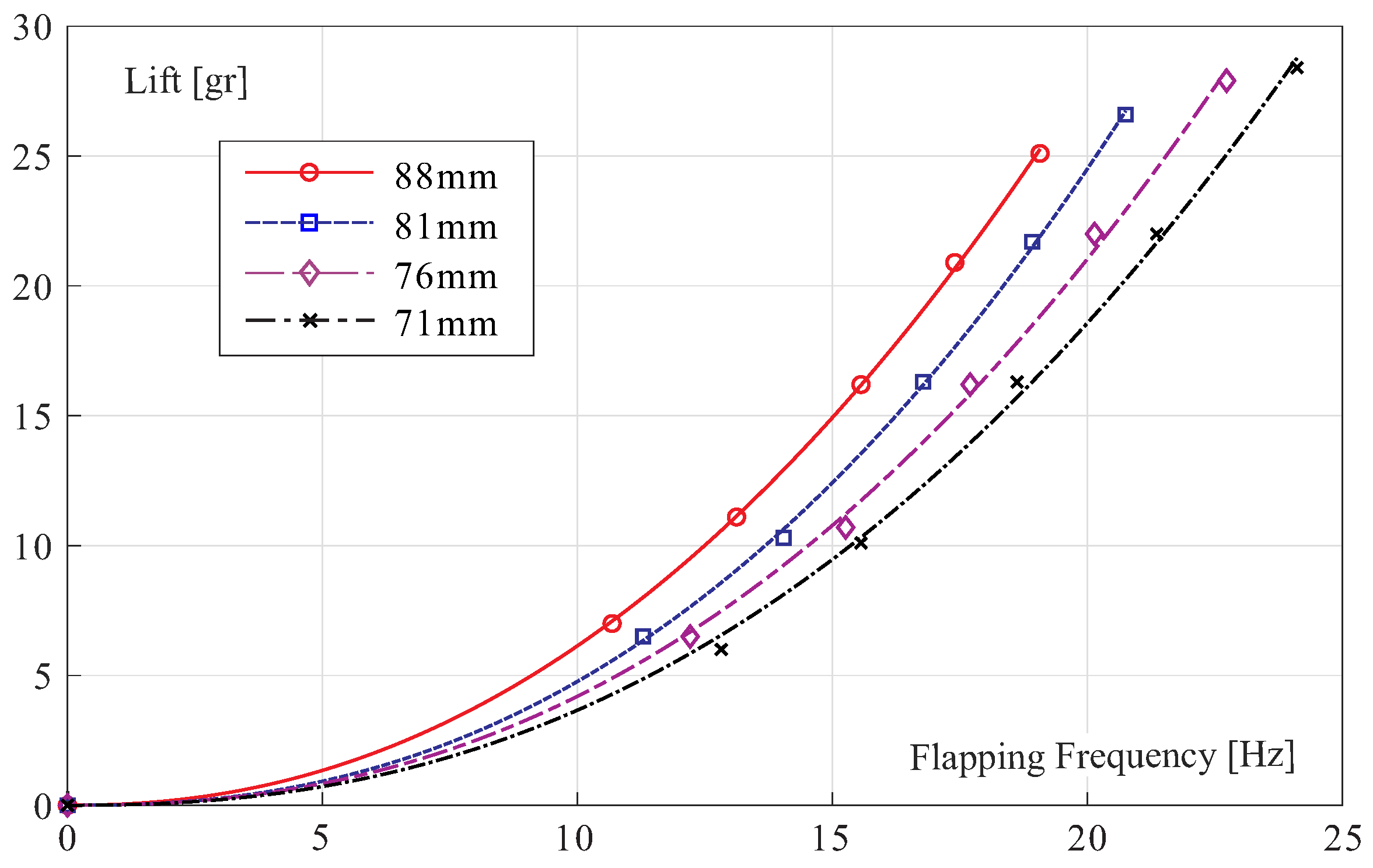
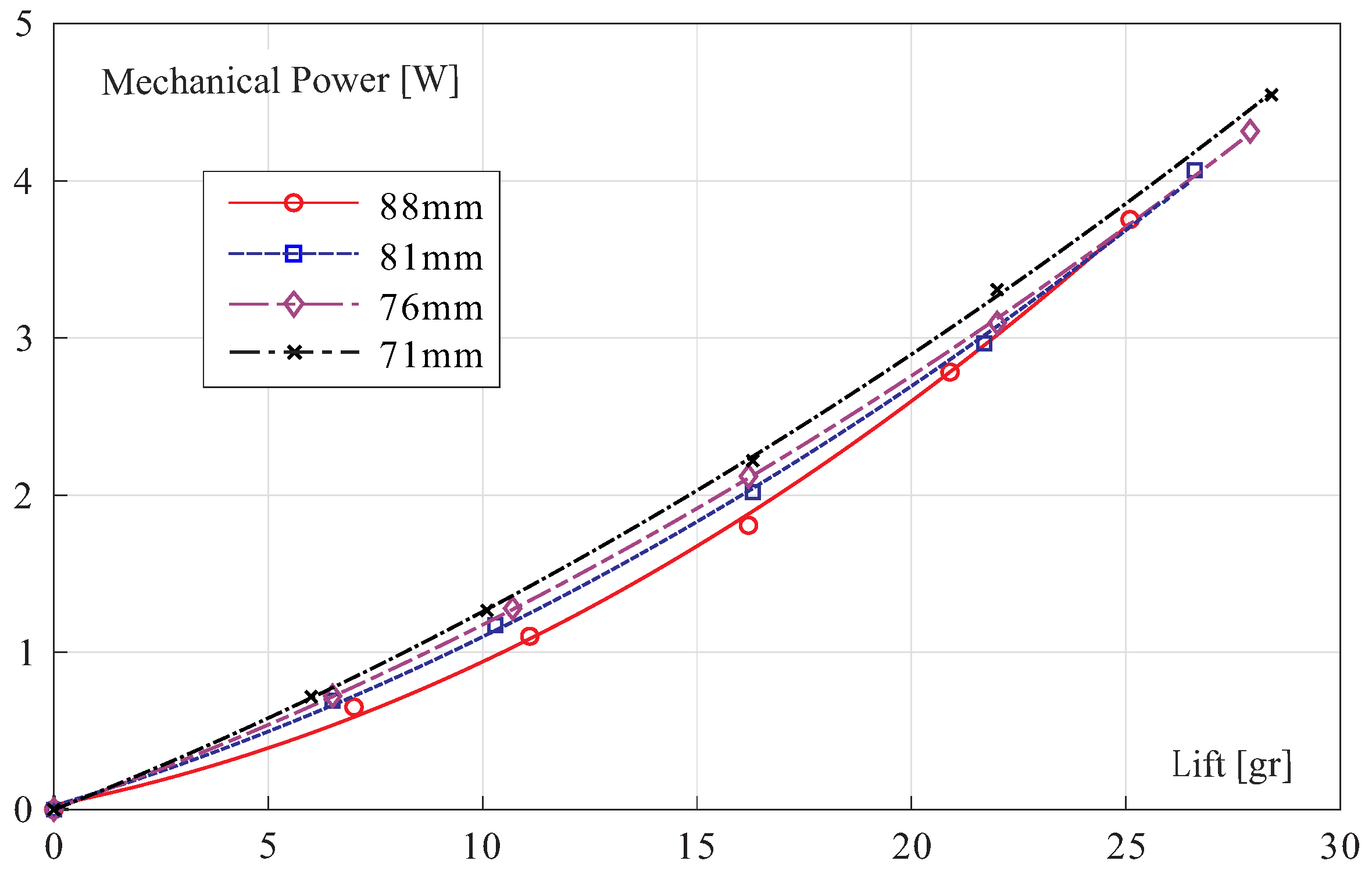
The experimental results are reported in Figure 5 which shows the evolution of the lift with the flapping frequency. As expected, a large wing produces more lift for the same flapping frequency, or they will flap at a lower frequency to achieve the same lift (we will return to this later in the design). Figure 6 shows the mechanical power at the motor output (it includes the power needed to generate the lift L and to overcome the friction in the motor, gearbox and transmission). Unlike the lift, there are no significant differences between the various wings, particularly in the range 20 gr 25 gr which is the most interesting part of the curves. In this range, the experimental data do not support the statement that “a given mass will be supported with less power by using a longer wing length and lower wing beat frequency” [10]. The specific mechanical power is around 135 W/kg, much below the value of 170 W/kg obtained earlier with a string transmission [6]. This value may be compared with the mass-specific power of ∼100 W/kg predicted in Figure 6 of [10] for a wing length of 80 mm and a flapping frequency of 20 Hz. The mass-specific power data indicate that the gear transmission is more efficient than the string transmission.
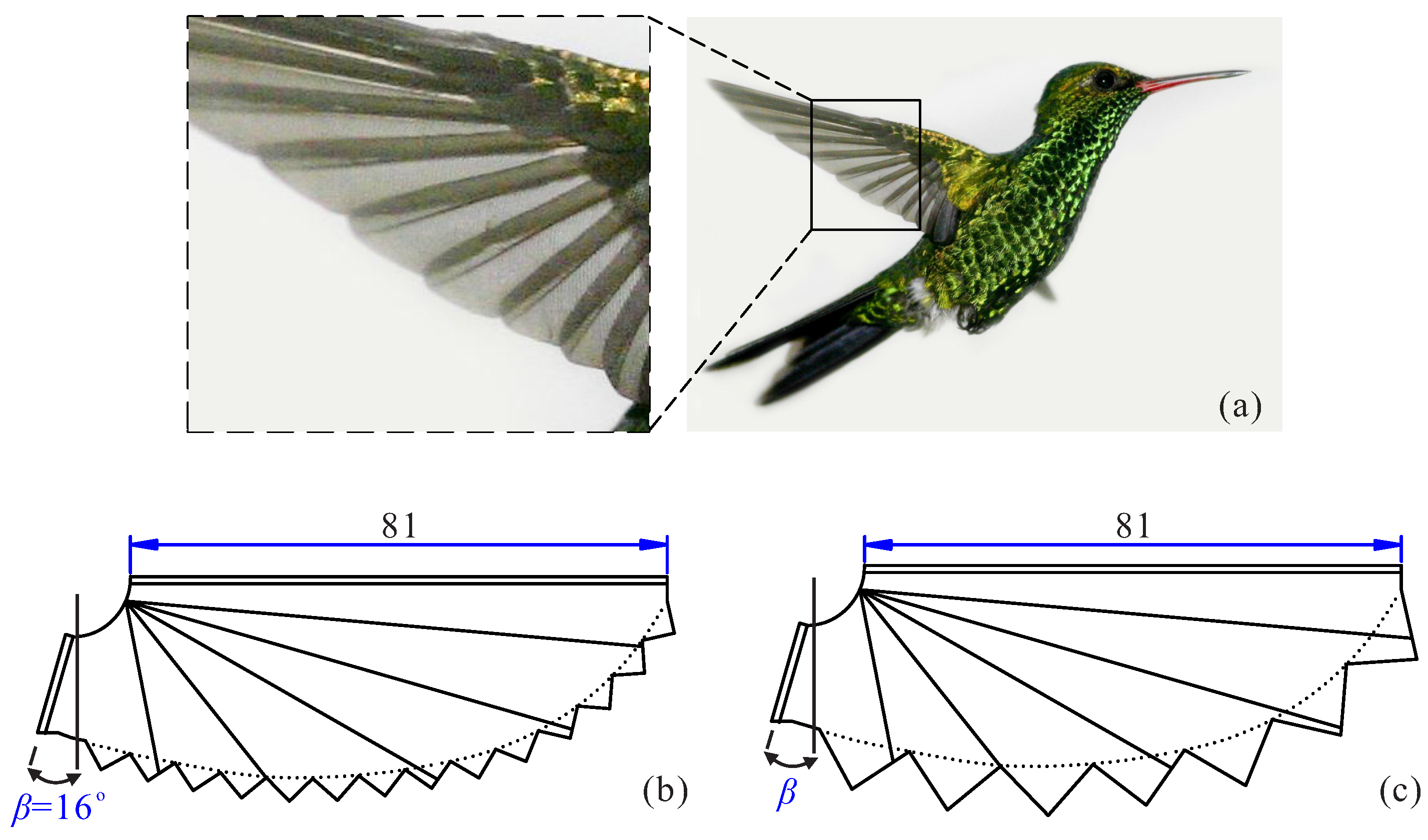
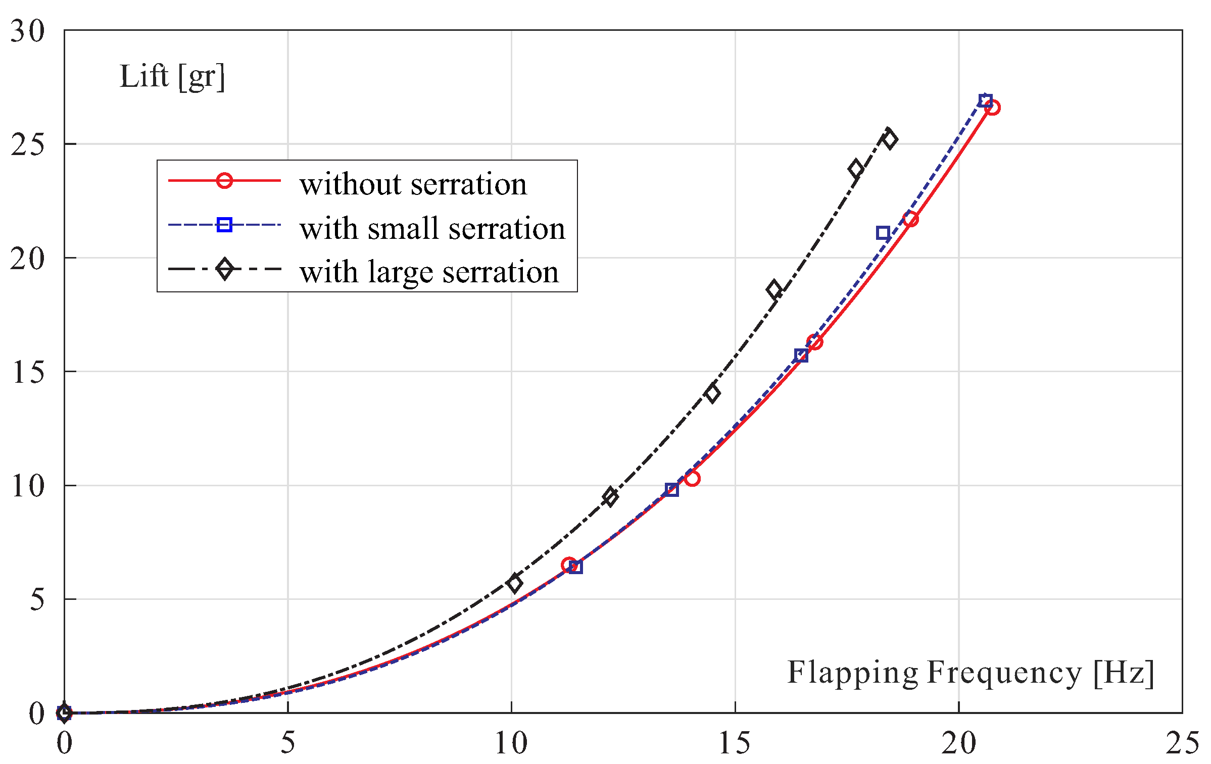
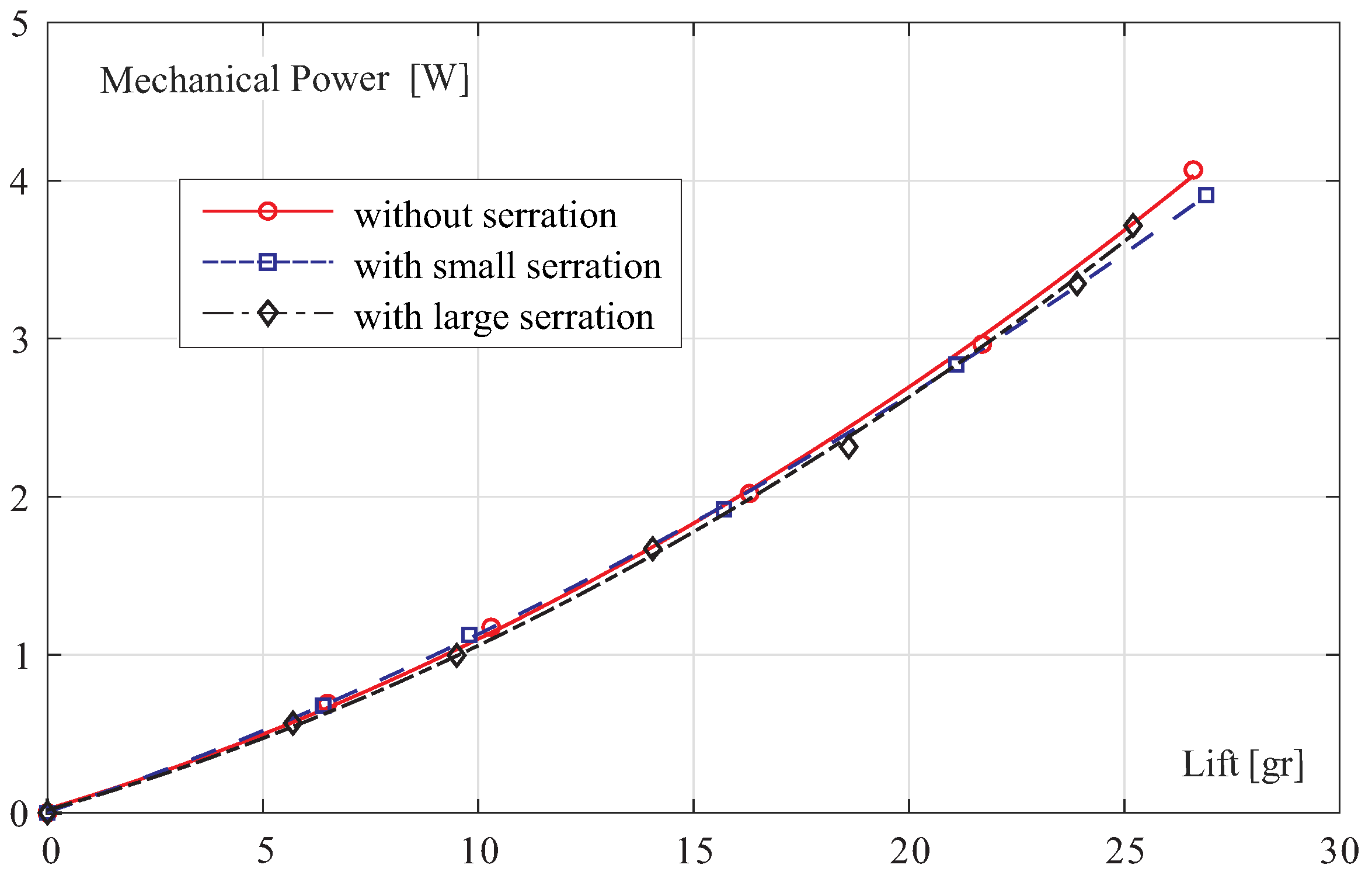
A trailing edge serration similar to that of natural hummingbirds has also been tested (Figure 7). The lift versus flapping frequency curves are shown in Figure 8 and the mechanical power versus lift is presented in Figure 9. No significant difference is observed in the mechanical power necessary to achieve a given lift; as in the previous case, the only difference is that the lift is obtained for a lower frequency when the wing area is larger. These wing shapes have not been studied further.
Weight Budget
Over the time, the COLIBRI project has experienced several modifications, leading to a total weight between 22 gr and 24 gr depending on the configuration. The current design includes several improvements such as a new state-of-the-art avionics (on-going). The attitude control mechanism involves 3 rotary actuators HK-5320 weighing 1.77 gr each (roll-pitch-yaw) [5]. However, to reduce their weight and improve their time response, the integrated electronics has been removed and the PWM control is managed directly by the main control board, reducing the weight to 1.26 gr each. Overall, the weight distribution excluding the battery is given in Table 1 below.
4. Battery
All batteries considered in this project are Li-polymer 3.7 V with various capacity and discharge rates (Table 2). Two options are considered: a single battery and two batteries in series. In the first case, the voltage of the motor cannot exceed significantly 3 V to exploit the full capacity of the battery. If two batteries are used in series, the motor voltage can be increased up to 6 V, but the total weight will be increased and more lift will be needed.
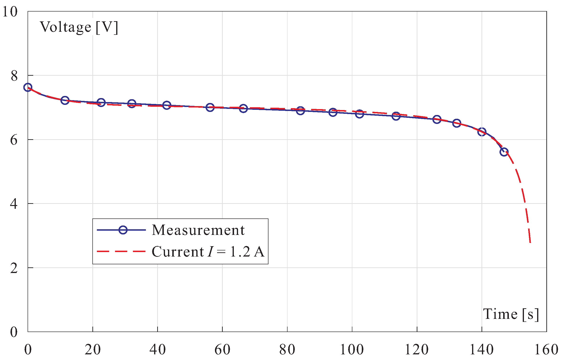
Figure 10 shows the discharge curve of two batteries B2 (Table 2) connected in series, for a discharge rate of 1.2 A (data from manufacturer). The voltage drop can be approximated fairly well by Shepherd model [11].
where e is the battery voltage (V), is the battery constant (initial) voltage, R is the internal resistance (), i is the battery current (A), A is the amplitude of the exponential zone at the beginning of the discharge curve (V), B is the constant controlling the initial exponential zone, Q is the capacity of the battery (mAh), is the battery discharge at time t, is the polarization resistance (). The best fit is obtained for V, , , mAh A·s, V, . This model allows prediction of the voltage drop for various current i.
5. DC Motor
For a given robot in hovering (lift L, gear ratio G, given wings), the flapping frequency f necessary to generate the lift L depends only on the flapping wings aerodynamics and does not depend on the motor. The same applies to the [cycle-averaged] mechanical power , where is the motor torque and is the motor speed (in rad/s), related to the flapping frequency f by the gear ratio, . The motor torque is related to the motor current I by where k is the motor constant (neglecting the no-load current, see Appendix A). From this formula,
the power dissipated in heat can be expressed
The first term, , can be regarded as a figure of merit of the motor; the second term depends on the gear ratio; a larger gear ratio will reduce the heat production. One can further observe that since the mechanical power to achieve the same lift with slightly different wings is nearly the same (Figure 6), it follows that smaller wings will flap faster, which will reduce the heat production. However, we will see that the gear ratio and the wing size also affect the voltage requirements and therefore the selection of the battery.
The set of (light and low-cost) motors considered in this study is listed in Table 3. Although lighter, the motor M4 can be eliminated because it has a significantly higher value of . In what follows, we will focus on M1 and M2. M1 has a low R a low k while M2 has higher R and k.
Three different gearboxes have been built and tested in the course of this project, all with two stages, made of low-cost toy components, with a gear ratio of respectively , and .
6. Design of the Lift-Production System
The lift-production system consists of the flapping wing, the gearbox, the DC motor and the battery. This study considers 4 different wings (Figure 4), 4 different batteries (Table 2) that can be used either alone or two in series, 4 different motors (Table 3) and 3 different gearboxes. We now examine how these subsystems can be arranged to maximize the flight time, i.e., to satisfy the voltage and current constraints on the battery and minimize the heat generated by the motor. We proceed as follows:
- Once a configuration wing-gearbox-motor-battery (W-G-M-B) has been selected, one can evaluate the lift L necessary for hovering (the weight of the robot). Then, from Figure 5, one can evaluate the flapping frequency f for the given wing size;
- From Figure 6, one can evaluate the mechanical power necessary to generate the lift L and overcome the friction in the mechanism. Since depends very little of the wing size, the same curve is used for all cases; it is approximated by (with and in this case);
- Knowing the flapping frequency f and the mechanical power , one can use the formula relating to the motor torque and speed :to calculate the current I (the no-load current is neglected for simplicity, but it can be included in the procedure without difficulty);
- The voltage can be calculated by the formulawhere k and R refer to the selected motor and G to the selected gearbox;
- Calculate the heat power ;
- The values of are compared to the maximum allowed for the selected battery: e should remain below the discharge curve for the discharge rate i which includes I, and the consumption of the attitude control servos and the main board (estimated in this project to 0.32 A if a single battery is used, or 0.25 A for two batteries in series).
Table 4 considers the case of a single battery (B3 in Table 2) and a motor with low k and R (M1 in Table 3) for various wing sizes (81 mm and 88 mm in Figure 4) and gear ratio (28.9 and 23.1). A large value of the voltage e will not allow to exploit the full discharge curve of the battery; larger wings (88 mm) or a smaller gear ratio () reduce the voltage e, but at the expense of a significant increase of the heat power .
Table 5 considers the case of two batteries in series (B2 in Table 2) and motor M2 with larger k and R. It compares the nominal wings (81 mm) with smaller ones (71 mm) and the nominal gear ratio () with a larger one (). Both options reduce the heat power . Surprisingly, despite the extra weight (22.8 gr instead of 21.6 gr), the solution with two batteries B2, when combined with shorter wings of 71 mm and a gear ratio of , leads to the smallest value of the heat power . For the nominal wing (W81) with the gearbox G39, the motor efficiency is ; this value may be compared with the value of reported in [5] for the same wings and the same gearbox, but with a string transmission.
7. Flight Time
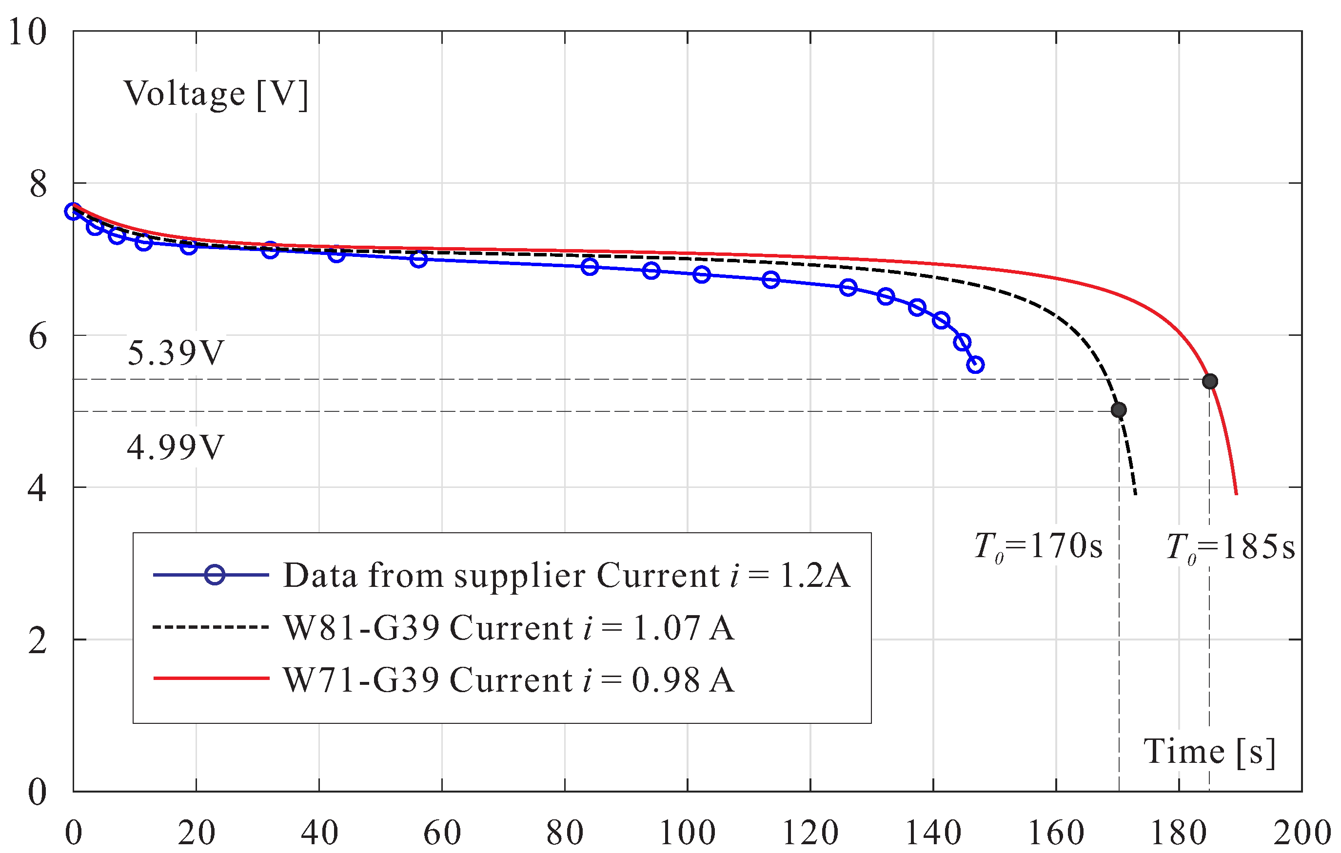
The flight time can be estimated by combining the data of the previous section with Shepherd’s model of the battery with the proper discharge rate. We illustrate the procedure with the two cases of Table 5 leading to the lowest values of the heat power (Table 6). The discharge current of the battery, i, is the sum of the motor current I and the current needed by the control board and the attitude control servos, estimated to 0.25 A in this case. Consider the discharge curve corresponding to A; the robot will be able to operate provided that the voltage available is larger than the voltage e requested. Let be the time when the discharge curve crosses the constant value e (Figure 11); beyond this point, the flight is impossible. Before , the duty factor of the PWM of the DC motor will be set to . Since the duty factor represents the fraction of time when the full available voltage is applied, the total flight time may be estimated by
The flight time T is reported in the last column of Table 6.
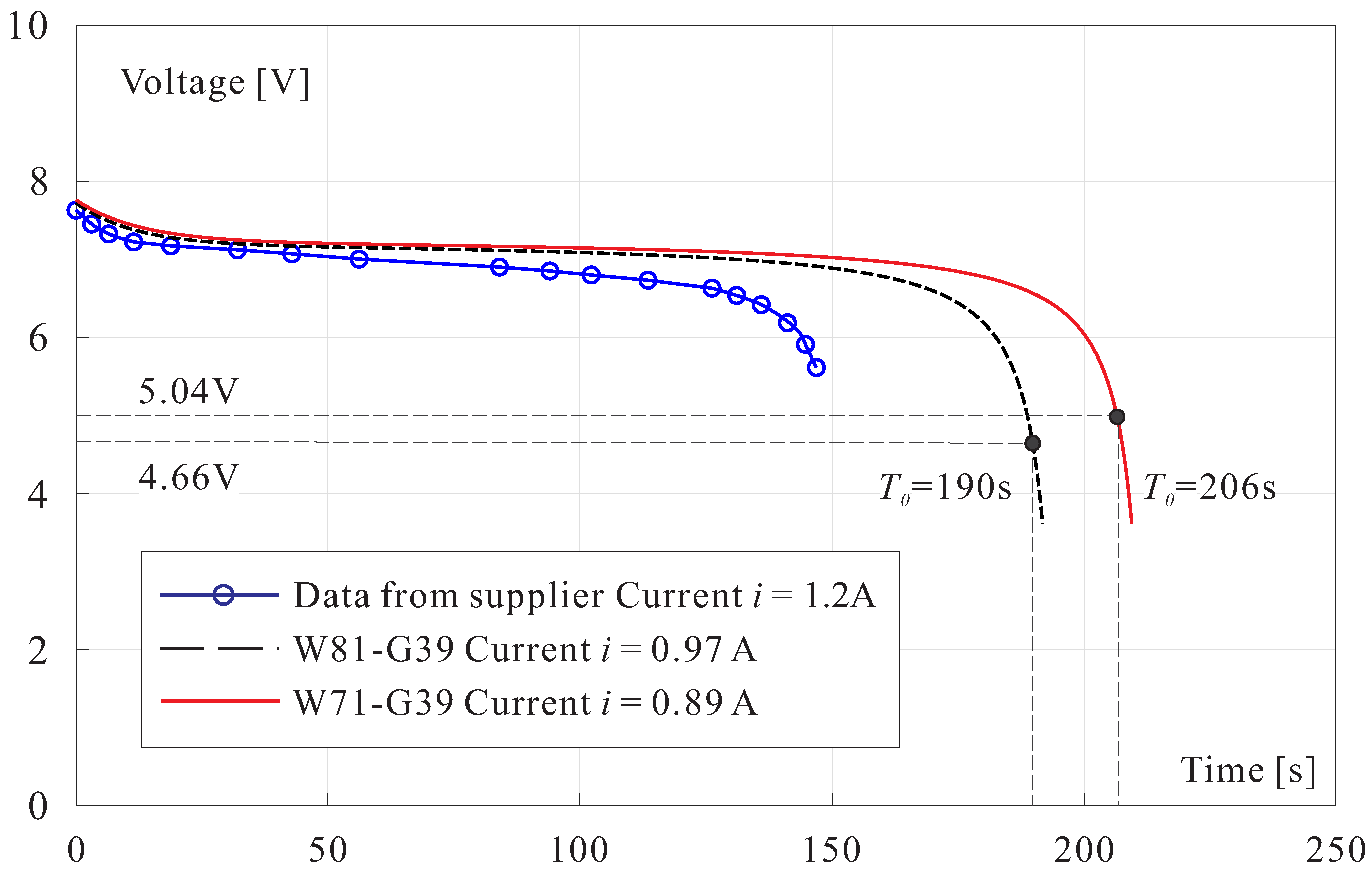
To evaluate the benefit of reducing the weight of the robot, Table 7 and Figure 12 illustrate the case when the lift is reduced to gr.
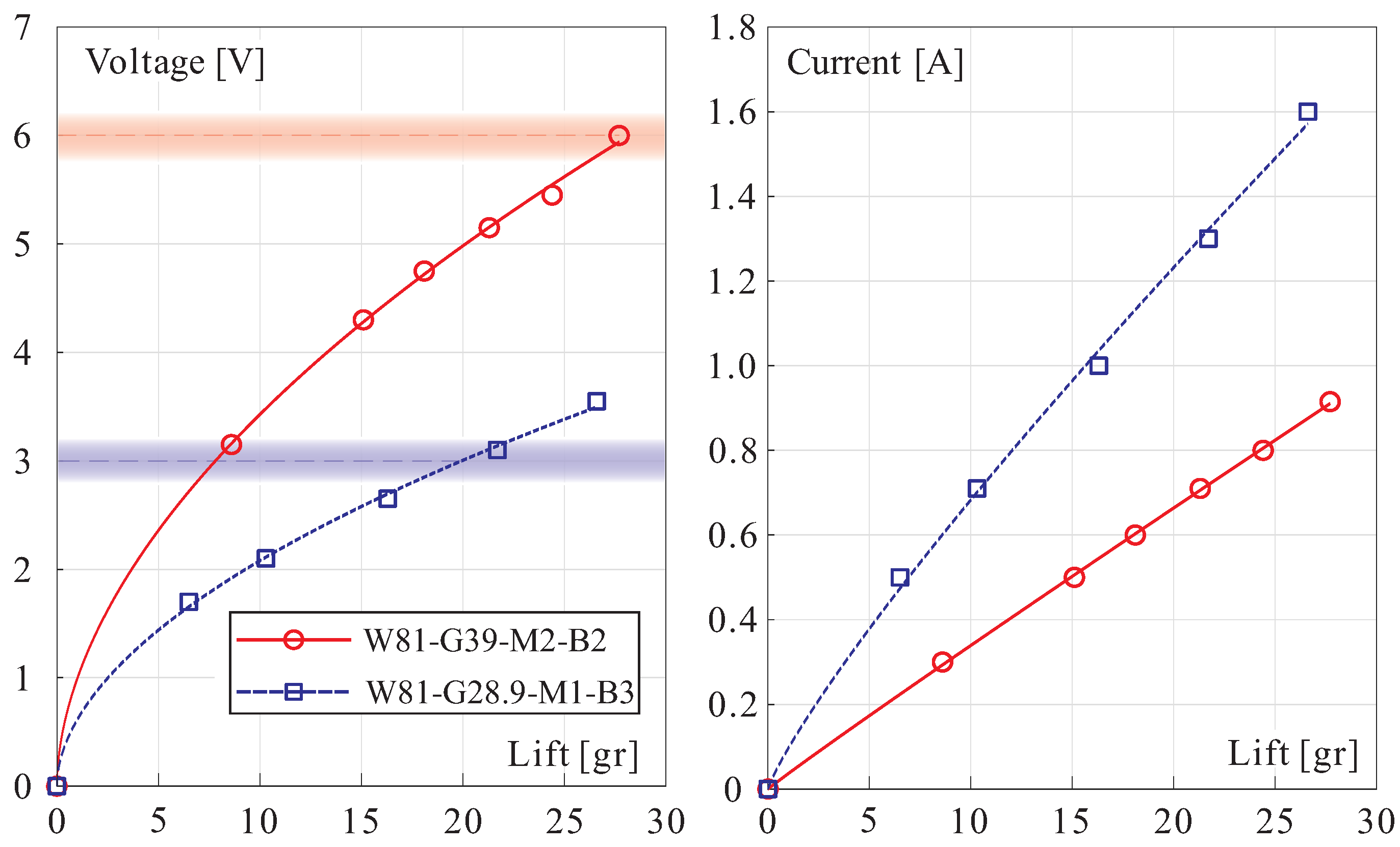
In the foregoing models, the operating voltage e of the motor was estimated using the motor constants R and k at room temperature. However, these values tend to deteriorate as the operating temperature increases (k decreases and R increases—see Appendix A). If a sufficient margin exists between the voltage v available at the battery and the motor voltage e, the duty factor of the PWM of the motor will be adapted by the flight controller to keep the lift constant. The margin between v and e will also be useful to generate a vertical acceleration. To illustrate this, consider the voltage versus lift curve of the configuration W81-G39-M2-B2 in Figure 13. A voltage of 5 V generates a lift of 20 gr while 6 V produces a lift of 28 gr. It follows that if a voltage of 6 V is applied to the motor of a hovering robot of 20 gr, an additional acceleration of m/s will be generated.
Please note that additional constraints may be associated with the maximum voltage allowed for the motor (6 V for motor M2), or the maximum current available at the battery.
Endurance Test
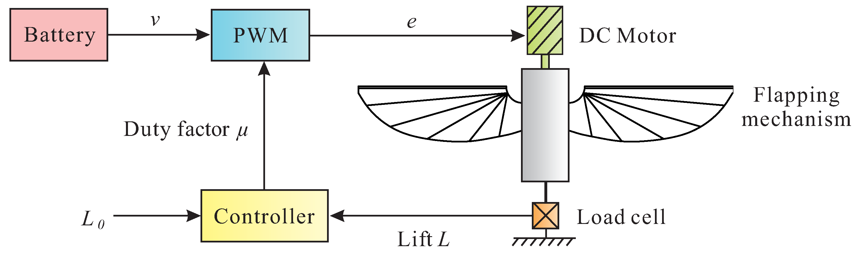
To confirm the predictions of the foregoing model, endurance tests have been conducted using the experimental set-up schematized in Figure 14. The flapping mechanism is attached to a load cell measuring the lift force L. A load cell with a capacity of 1 kg is used in order to track the strong force variations during the flapping cycle; it is connected to a Wheatstone bridge; a weight of 20 gr is used for calibration. The signal is amplified and fed into an ADC (dSPACE) at 10 kHz and transferred to Matlab; the signal is low-pass filtered (second order Butterworth filter with a cut-off frequency of 1 Hz) to provide the average lift L which is compared with the requested lift (22.8 gr in this case) and the duty factor of the PWM of the DC motor is adjusted as the battery discharges thanks to an Arduino Due board and a Darlington transistor TIP120.
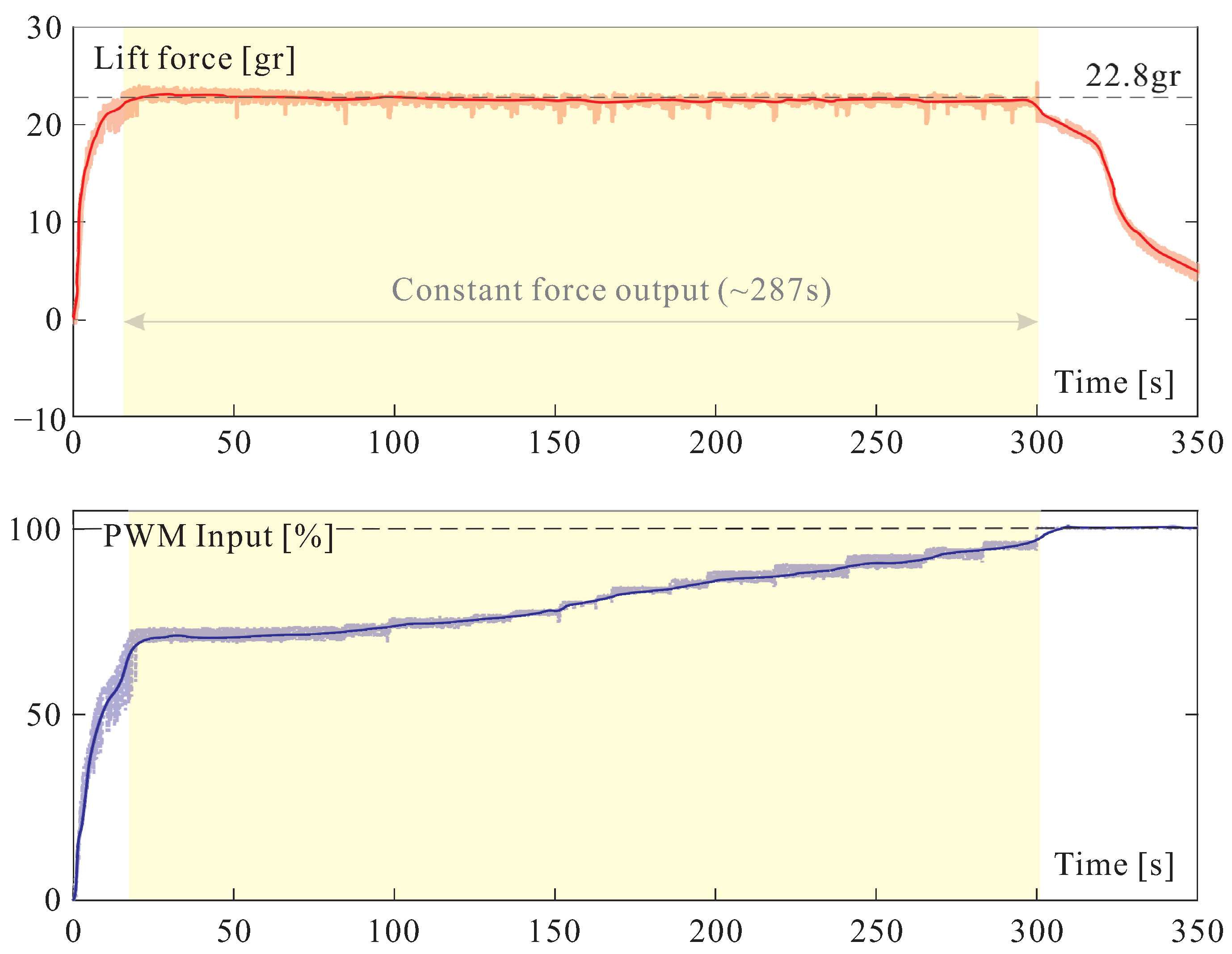
Figure 15 shows a discharge experiment of the system W81-G39-M2-B2. The motor M2 used in this experiment has the following characteristics at room temperature: , V·s. The no-load current of the complete mechanism is estimated to A. The duty factor of the PWM is adjusted visually to keep the lift to 22.8 gr. For this experiment, V and A.
The upper part of Figure 15 shows the time history of the lift force and the lower part shows the time history of the duty factor of the PWM. One sees that is increasing over time, to compensate for the voltage drop at the battery output and the changes in the motor constants during the test. When reaches 100%, the lift force can no longer be maintained to the requested value and it drops rapidly. In this experiment, the lift 22.8 gr was kept for 287 s, nearly 5 min. The fact that this value is larger than the predicted 237 s (first line in Table 6) may look surprising, but the current used in the experiment is only 0.8 A (it does not include the current needed to run the control board and the attitude control servos). Performing the discharge simulation with this value of the current leads to an estimated flight time of 289 s (!). To be honest, one must say that the experimental value may vary significantly from one motor to another of the same type. Also, the contact temperature measured on the motor housing has been found to vary from one experiment to another; for the experiment reported in Figure 15, the end temperature was only 32.6 °C.
8. Power-to-Lift Ratio
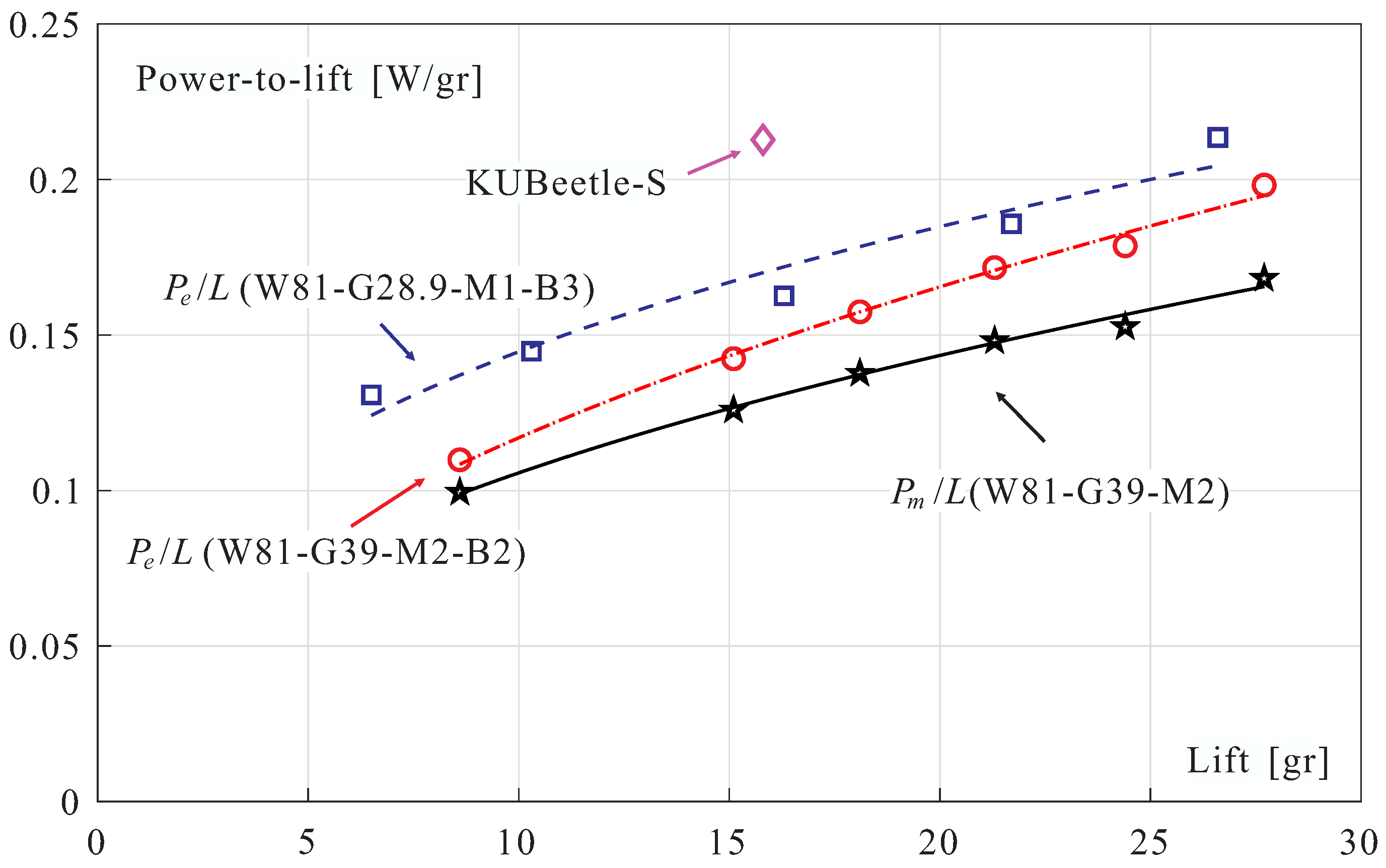
Returning to the power-to-lift ratio which was briefly addressed earlier in the paper, Figure 16 shows the power-to-lift ratio as a function of the lift L for the two configurations considered above. The mechanical power is dominated by the power needed to overcome the aerodynamic forces. The electrical power depends on the whole system. For comparison purposes, the figure also includes the value corresponding to the KUBeetle-S project of Konkuk University (estimated from Figure 5 of [8]).
9. Conclusions
This paper has analyzed the lift-production system of the COLIBRI robot. A new gear transmission has been designed and tested to replace the former string transmission of the flapping wing mechanism. The gear transmission has been found more efficient and easier to assemble. The mechanical power needed to overcome the friction in the mechanism has been substantially reduced. The overall mechanical power is dominated by its aerodynamic contribution. A sensitivity analysis has been performed of wings of similar shapes but different sizes; all the wings investigated exhibit a similar efficiency (same mechanical power to achieve a given lift). Trailing edge serrations have been tested, but they do not seem to provide an improved aerodynamic efficiency.
Two battery configurations have been analyzed: a single battery of 3.7 V with a higher current capability and two batteries in series offering 2 × 3.7 V with a lower current. Various combinations have been compared, with different motor characteristics (k and R), different gearbox ratio G and different wing size. The ratio can be regarded as a figure of merit when comparing DC motors of similar sizes.
The flight time has been estimated using Shepherd’s discharge model. Despite a larger mass, the best performances have been obtained with the configuration involving two batteries in series, a motor with larger values of k and R (motor M2), and a large value of the gear ratio . The numerical prediction of the flight time have been confirmed by experiments. The overheating of the motor observed previously has been eliminated and a flight time of nearly 5 min was observed.
Author Contributions
Conceptualization, A.P., H.W., S.K., K.W. and A.R.; software, H.W., S.K.; validation, A.P., H.W., S.K., K.W. and A.R.; writing—original draft preparation, A.P.; writing—review and editing, A.P., H.W. and S.K.; supervision, A.P. All authors have read and agreed to the published version of the manuscript.
Funding
This research received no external funding.
Institutional Review Board Statement
Not applicable.
Informed Consent Statement
Not applicable.
Data Availability Statement
Data is contained within the article.
Acknowledgments
Han Wang and Shengzheng Kang were supported by the China Scholarship Council.
Conflicts of Interest
The authors declare no conflict of interest.
Appendix A. Motor Equations
A DC motor is governed by the following equations:
where e is the input voltage, I is the current, k is the motor constant (in V· s or Nm/A) and R is the internal resistance. is the output torque and is the no-load current necessary to compensate the motor internal friction. The total electrical power is
The heat power is
and the mechanical power
or alternatively
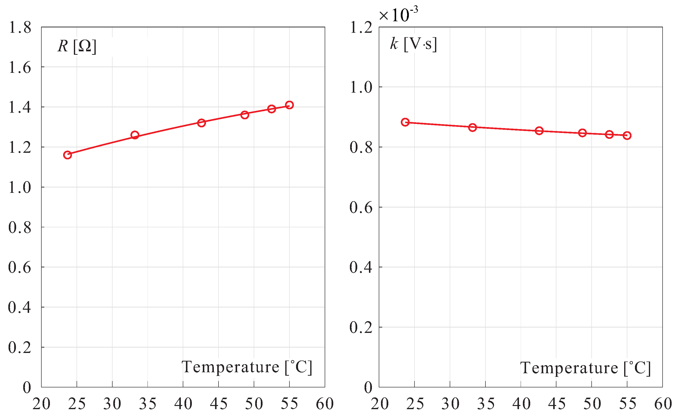
includes the mechanical power of the flapping wings and the internal friction. Both R and k depend on the operating temperature as illustrated in Figure A1 for motor M2. R increases with temperature while k reduces, in such a way that the performance of motor tends to deteriorate.
Figure A1.
Evolution of the internal resistance R (left) and the motor constant k with the motor M2 housing temperature.
Figure A1.
Evolution of the internal resistance R (left) and the motor constant k with the motor M2 housing temperature.

References
- Keennon, M.T.; Klingebiel, K.R.; Won, H.; Andriukov, A. Development of the nano hummingbird: A tailless flapping wing micro air vehicle. In 50th AIAA Aerospace Sciences Meeting Including the New Horizons Forum and Aerospace Exposition; AIAA: Nashville, TN, USA, 2012; pp. 1–24. [Google Scholar]
- Phan, H.V.; Park, H.C. Insect-inspired, tailless, hover-capable flapping-wing robots: Recent progress, challenges, and future directions. Prog. Aerosp. Sci. 2019, 111, 100573. [Google Scholar] [CrossRef]
- Roshanbin, A.; Altartouri, H.; Karasek, M.; Preumont, A. COLIBRI: A Hovering Flapping Twin-Wing Robot. Int. J. Micro Air Veh. 2017, 9, 270–282. [Google Scholar] [CrossRef] [Green Version]
- Karásek, M. Robotic Hummingbird: Design of a Control Mechanism for a Hovering Flapping Wing Micro Air Vehicle. Ph.D. Thesis, Université Libre de Bruxelles, Brussels, Belgium, November 2014. [Google Scholar]
- Roshanbin, A. Design and Development of a Tailless Robotic Hummingbird. Ph.D. Thesis, Université Libre de Bruxelles, Brussels, Belgium, September 2019. [Google Scholar]
- Roshanbin, A.; Abad, F.; Preumont, A. Kinematic and Aerodynamic Enhancement of a Robotic Hummingbird. AIAA J. 2019. [Google Scholar] [CrossRef]
- Controlled Flight of a Tailless Flapping Twin-Wing Robot. Available online: https://www.youtube.com/watch?v=-5-o9tvbziE (accessed on 2 October 2018).
- Phan, H.V.; Aurecianus, S.; Au, T.K.L.; Kang, T.; Park, H.C. Towards Long-Endurance Flight of an Insect-Inspired, Tailess, Two-Winged, Flapping-Wing Flying Robot. In IEEE Robotics and Automation Letters PP(99):1-1; IEEE: Piscataway, NJ, USA, 2020. [Google Scholar] [CrossRef]
- Phan, H.V.; Taesam, K.; Park, H.C. Design and Stable Flight of a 21 g Insect Like Tailless Flapping Wing Micro Air Vehicle with Angular Rates Feedback Control. Bioinspiration Biomim. 2017, 12, 036006. [Google Scholar] [CrossRef] [PubMed]
- Ellington, C.P. The novel aerodynamics of insect flight: Applications to micro-air vehicles. J. Exp. Biol. 1999, 202, 3439–3448. [Google Scholar] [PubMed]
- Shepherd, C.M. Design of Primary and Secondary Cells-Part 2. An Equation Describing Battery Discharge. J. Electrochem. Soc. 1965, 112, 657–664. [Google Scholar] [CrossRef]
Figure 1.
The COLIBRI robot.

Figure 2.
Evolution of the transmission mechanism of the COLIBRI robot. Top: string transmission. Bottom: gear transmission.
Figure 2.
Evolution of the transmission mechanism of the COLIBRI robot. Top: string transmission. Bottom: gear transmission.

Figure 3.
Exploded view of the flapping mechanism with gear transmission of the COLIBRI robot.

Figure 4.
Wings of various sizes, (a) 81 mm (nominal), (b) 88 mm, (c) 76 mm, (d) 71 mm. The nominal wing is represented in dotted lines.
Figure 4.
Wings of various sizes, (a) 81 mm (nominal), (b) 88 mm, (c) 76 mm, (d) 71 mm. The nominal wing is represented in dotted lines.


Figure 6.
Mechanical power vs. lift L for the wings of Figure 4.
Figure 6.
Mechanical power vs. lift L for the wings of Figure 4.

Figure 7.
Wings with trailing edge serration. (a) Hummingbird Chlorostilbon canivetii (source: Wikipedia). (b) Small serration. (c) Large serration. The nominal wing is in dotted line.
Figure 7.
Wings with trailing edge serration. (a) Hummingbird Chlorostilbon canivetii (source: Wikipedia). (b) Small serration. (c) Large serration. The nominal wing is in dotted line.

Figure 8.
Lift vs. flapping frequency for the wings with trailing edge serration.

Figure 9.
Mechanical power vs. lift L for the wings with trailing edge serration.

Figure 10.
Discharge curve of two batteries B2 in series for a discharge rate of 1.2 A (data from manufacturer). The dashed line is the best fit Shepherd model.
Figure 10.
Discharge curve of two batteries B2 in series for a discharge rate of 1.2 A (data from manufacturer). The dashed line is the best fit Shepherd model.

Figure 11.
22.8 gr. Discharge curve of two batteries B2 in series for a discharge rate of 1.07 A ( s) and 0.98 A ( s).
Figure 11.
22.8 gr. Discharge curve of two batteries B2 in series for a discharge rate of 1.07 A ( s) and 0.98 A ( s).

Figure 12.
20 gr. Discharge curve of two batteries B2 in series for a discharge rate of 0.97 A ( 190 s) and 0.89 A ( 206 s).
Figure 12.
20 gr. Discharge curve of two batteries B2 in series for a discharge rate of 0.97 A ( 190 s) and 0.89 A ( 206 s).

Figure 13.
Voltage vs. Lift (left) and Current vs. Lift (right) for two flight configurations (with a single battery B3 and two batteries B2 in series). The shaded areas correspond to the voltage limits.
Figure 13.
Voltage vs. Lift (left) and Current vs. Lift (right) for two flight configurations (with a single battery B3 and two batteries B2 in series). The shaded areas correspond to the voltage limits.

Figure 14.
Experimental set-up for the endurance test.

Figure 15.
Endurance experiment. Top: Time history of the lift force. Bottom: Time history of the duty factor of the PWM. The lift drops suddenly when reaches 100%.
Figure 15.
Endurance experiment. Top: Time history of the lift force. Bottom: Time history of the duty factor of the PWM. The lift drops suddenly when reaches 100%.

Figure 16.
Power-to-lift ratio vs. Lift. is the mechanical power and is the electrical power. The value of the KUBeetle-S project is given for comparison.
Figure 16.
Power-to-lift ratio vs. Lift. is the mechanical power and is the electrical power. The value of the KUBeetle-S project is given for comparison.


Table 1.
Weight breakdown excluding the battery. The motors M1 and M2 refer to Table 3.
| Component | Weight [gr] |
|---|---|
| Flapping mechanism | 7.2 |
| Attitude control servos | 3.8 |
| Motor | 3.9 (M1) 3.6 (M2) |
| Avionics (including Bluetooth) | 2 |
| Carbon rods | 0.5 |
| Lines and connectors | 1.2 |
| Total | 18.6 (M1) 18.3 (M2) |
Table 2.
Characteristics of the batteries.
| N° | Reference | Capacity | Weight | Discharge Rate | Max. Current |
|---|---|---|---|---|---|
| [mAh] | [gr] | [A] | |||
| B1 | Zippy LiPo | 50 | 1.51 | 20C | 1 |
| B2 | Hyperion G5 | 70 | 2.26 * | 25C–30C | 1.75–2.1 |
| LiPo | (50C burst) | ||||
| B3 | Hyperion G5 | 100 | 3.00 ** | 25C–30C | 2.5–3 |
| LiPo | (50C burst) | ||||
| B4 | Eastfire LiPo | 100 | 3.01 | 30C | 3 |
* 2.37 gr before removing useless weight. ** 3.11 gr before removing useless weight.
Table 3.
Characteristics of the motors considered in this study.
| N° | Producer | Weight [gr] | V·s] | [] | |
|---|---|---|---|---|---|
| M1 | Chaoli | 3.87 | 0.63 | 6.75 | 0.0138 |
| M2 | Micron Wings | 3.59 | 1.2 | 8.44 | 0.0143 |
| M3 | Songyang | 3.56 | 0.76 | 7.09 | 0.0151 |
| M4 | Micron Wings | 2.88 | 0.87 | 5.90 | 0.025 |
Table 4.
Single battery B3 and Motor M1: Influence of the wing size and the gearbox. Flapping frequency f, mechanical power , current I, voltage e, heat power and total electric power . The lift is 21.6 gr in all cases.
Table 4.
Single battery B3 and Motor M1: Influence of the wing size and the gearbox. Flapping frequency f, mechanical power , current I, voltage e, heat power and total electric power . The lift is 21.6 gr in all cases.
| Wing-Gearbox | f [Hz] | [W] | I [A] | e [V] | [W] | [W] |
|---|---|---|---|---|---|---|
| W81-G28.9 | 18.96 | 2.84 | 1.22 | 3.10 | 0.94 | 3.78 |
| W81-G23.1 | 18.96 | 2.84 | 1.53 | 2.82 | 1.47 | 4.31 |
| W88-G28.9 | 17.75 | 2.84 | 1.31 | 3.00 | 1.08 | 3.93 |
| W88-G23.1 | 17.75 | 2.84 | 1.63 | 2.77 | 1.67 | 4.51 |
Table 5.
Two batteries B2 in series and Motor M2: Influence of the wing size and the gearbox. Flapping frequency f, mechanical power , current I, voltage e, heat power and total electric power . The lift is gr in all cases.
Table 5.
Two batteries B2 in series and Motor M2: Influence of the wing size and the gearbox. Flapping frequency f, mechanical power , current I, voltage e, heat power and total electric power . The lift is gr in all cases.
| Wing-Gearbox | f [Hz] | [W] | I [A] | e [V] | [W] | [W] |
|---|---|---|---|---|---|---|
| W81-G28.9 | 19.4 | 3.23 | 1.09 | 4.28 | 1.42 | 4.66 |
| W81-G39 | 19.4 | 3.23 | 0.82 | 4.99 | 0.80 | 4.03 |
| W71-G28.9 | 21.8 | 3.23 | 0.97 | 4.5 | 1.13 | 4.36 |
| W71-G39 | 21.8 | 3.23 | 0.73 | 5.39 | 0.62 | 3.86 |
Table 6.
Two batteries B2 in series and Motor M2. Lift: 22.8 gr. I is the motor current and i is the battery discharge current. T is the estimated flight time.
Table 6.
Two batteries B2 in series and Motor M2. Lift: 22.8 gr. I is the motor current and i is the battery discharge current. T is the estimated flight time.
| Wing-Gearbox | [W] | I [A] | e [V] | i [A] | [s] | T [s] |
|---|---|---|---|---|---|---|
| W81-G39 | 0.80 | 0.82 | 4.99 | 1.07 | 170 | 237 |
| W71-G39 | 0.62 | 0.73 | 5.39 | 0.98 | 185 | 241 |
Table 7.
Two batteries B2 in series and Motor M2. Lift: 20 gr. I is the motor current and i is the battery discharge current. T is the estimated flight time.
Table 7.
Two batteries B2 in series and Motor M2. Lift: 20 gr. I is the motor current and i is the battery discharge current. T is the estimated flight time.
| Wing-Gearbox | [W] | I [A] | e [V] | i [A] | [s] | T [s] |
|---|---|---|---|---|---|---|
| W81-G39 | 0.62 | 0.72 | 4.66 | 0.97 | 190 | 285 |
| W71-G39 | 0.49 | 0.64 | 5.04 | 0.89 | 206 | 288 |
Publisher’s Note: MDPI stays neutral with regard to jurisdictional claims in published maps and institutional affiliations. |
© 2021 by the authors. Licensee MDPI, Basel, Switzerland. This article is an open access article distributed under the terms and conditions of the Creative Commons Attribution (CC BY) license (http://creativecommons.org/licenses/by/4.0/).
Share and Cite
MDPI and ACS Style
Preumont, A.; Wang, H.; Kang, S.; Wang, K.; Roshanbin, A. A Note on the Electromechanical Design of a Robotic Hummingbird. Actuators 2021, 10, 52. https://0-doi-org.brum.beds.ac.uk/10.3390/act10030052
AMA Style
Preumont A, Wang H, Kang S, Wang K, Roshanbin A. A Note on the Electromechanical Design of a Robotic Hummingbird. Actuators. 2021; 10(3):52. https://0-doi-org.brum.beds.ac.uk/10.3390/act10030052
Chicago/Turabian StylePreumont, André, Han Wang, Shengzheng Kang, Kainan Wang, and Ali Roshanbin. 2021. "A Note on the Electromechanical Design of a Robotic Hummingbird" Actuators 10, no. 3: 52. https://0-doi-org.brum.beds.ac.uk/10.3390/act10030052
Note that from the first issue of 2016, this journal uses article numbers instead of page numbers. See further details here.