1. Introduction
The use of shape memory alloy (SMA) represents a technological opportunity for actuation systems where the conventional actuators present limitations, especially for wearable, soft robotics automotive, and aerospace applications. This type of actuator provides various advantages compared with the conventional actuators, such as high energy density, low weight and high force, flexibility, noiseless operation, simple structure, easy integration into a new system, and low volume. SMAs can generate a force of 150 times higher compared with the hydraulic actuators and 400 times higher force compared with the magnetic actuators at the same volume. The SMA actuators provide relatively low-cost solution compared with other actuators. These advantages make this type of actuator a suitable alternative for linear or rotative conventional actuators, but they have some disadvantages such as poor integration in physical systems, low working frequency, high power consumption, and elevated hysteresis in its behavior.
SMAs are combinations of two or more metals that, in certain proportions and with the appropriate heat treatment, can remember a predetermined shape when applying heat. This alloy can be found in different combinations of NiTi with Co, Fe, Al, etc. to modify properties such as activation temperature, elasticity, and so on [
1]. The most common alloy is NiTi, or nitinol, since it shows resistance to heat and fatigue [
2].
The working principle of this type of actuator is based on its thermal activation between two phases of transformation: martensite at low temperatures and austenite at high temperatures. The most common activation is based on the Joule effect in which the electrical energy is transformed into thermal energy and, after that, into mechanical work. Between these two phases, the NiTi alloys can present a deformation of around 3–5% from its total length. This isotherm process and the phase transformation from austenite to martensite, which occur under an external load, represent the superelasticity effect (SE).
Due to its characteristics, this type of material has been used as an actuator in different applications in the biomedical, automation, aerospace, and robotics fields [
3], but still has some limitations such as a relatively small strain (3–5% of its total length) compared with other actuators such as shape memory polymer (SMP) or dielectric elastomer actuators (DEAs) [
4], low work frequency, controllability (due its nonlinearities), and energy efficiency. To improve these aspects, many SMA-based actuators with different configurations or external mechanisms have been developed to address one of the major challenges: the work frequency. Several studies [
5,
6,
7,
8] have demonstrated that the SMA activation speed can be significantly improved by heating the SMA using the Joule effect. Nevertheless, the most critical limitation occurs in the cooling stage, where heat convection and conduction play the principal role. With the principal objective of improving the cooling process, several researchers have proposed different configurations of SMA actuators with passive or active cooling mechanisms. The authors of [
9,
10,
11] studied the effect of SMA cooling with air flow, while the authors of [
10,
11,
12] studied the effect of water circulation on cooling SMA wires. Pathak et al. [
10] and Tadesse et al. [
11] studied thermal grease as an SMA heat sink. The authors of [
13,
14,
15] presented different SMA actuators composed of multiple SMA wires, which improve the work frequency of the actuator. Although these methods improve the cooling process, they increase the complexity of the actuator structure, introducing new components. These methods hinder some of the advantages of the actuator over the conventional actuators.
In our research group, an SMA actuator based on the Bowden cable was successfully used in different prototypes of rehabilitation devices such as an upper limb rehabilitation exoskeleton [
16,
17] and robotic applications such as an exo-muscular system for assisting astronauts during extravehicular activities [
18]. The results of the actuation mode of these devices show a promising future for SMA actuators, especially in situations where an actuator with low weight, noiseless operation, and biocompatibility that is not affected by corrosion and magnetic fields as easily as conventional motors is required. The SMA actuator offers the advantages of small dimensions and flexibility, making it good option for miniature, soft, and wearable devices. Different control approaches were tested for these applications [
19]; however, the use of this type of material remains limited due to its disadvantages, for instance, high energy consumption and low work frequency. In several studies, the control of SMA actuators with the pulse width modulation (PWM) method was studied and compared with other methods. The results demonstrate that this method consumes less energy [
20]. In addition, if the pulses are of the millisecond order and high voltage, the efficiency is improved [
21,
22,
23].
From a review of the literature on SMA actuator efficiency according to its configuration, we found several publications. Thrasher et al. [
21] presented a systematic efficiency analysis of two SMA actuators: an SMA elevator and an SMA antagonistic configuration. The efficiency for both configurations was calculated for different ratios of strain and yield stress, and the results were compared with the Carnot efficiencies. The Carnot efficiencies for the both actuators was less than 10% and the antagonist configuration showed 50% lower efficiency than the SMA elevator.
Motzki et al. [
22] demonstrated that the efficiency of the SMA actuator and its velocity of contraction increase if the actuator is operated with high-voltage pulses for a short time interval. However, the basic idea is to quickly contract the actuator so as not to lose heat in the environment, limiting the actuator from working at high speeds.
In terms of the practical applications of SMA actuators, the energy consumption and the displacement that they produce in relation to the percentage of contraction are the parameters determining their performance. In this work, different configurations of SMA-based actuators were analyzed according to both characteristics, to help guide the choice of an optimal actuator in terms of consumption and displacement for a specific application. In some practical applications, for example, in the development of some types of exoskeletons, the length of the SMA wires in the actuation system can be an important parameter that limits the usability of the device; reducing the size may be convenient even if precision is lost in position control. In other applications, energy consumption can be the determining parameter allowing the use of SMA-based actuators. Therefore, different SMA-based actuator configurations used in our research group were described and analyzed in a test bench equipped with various sensors.
This paper is divided into four sections.
Section 2 presents the methodology of this work. Here, the SMA wire thermal model, the test bench, the configuration of the actuators and their controls, and the tests setup is presented. In
Section 3, the preliminary results are detailed and analyzed.
Section 4 provides the conclusions of this study.
2. Methodology
This section presents the SMA wire thermal model, the test bench (where the tests with SMA actuators were performed), the various SMA actuators configurations and their characteristics, and the proposed tests setup.
2.1. SMA Thermal Model
A series of models has been proposed to describe SMA behavior. These models relate the state variables such as stress (
), strain (
), temperature, and the martensite ratio. This last variable measures the amount of martensite relative to the austenite in a specific time. Tanaka [
24] proposed a model that describes SMA thermo-mechanical behavior:
where
T is the temperature and
is the martensite ratio. The material parameters
E,
, and
represent the elastic modulus (Young’s modulus), the thermoelastic tensor, and the transformation tensor, respectively. According to Tanaka [
24], these parameters can be assumed to be constant. The stress is defined as
and the strain is
, where
F represents the applied force,
a is the section area, and
l is the SMA length. The martensite ratio
depends on the applied stress and the temperature wire, being
for complete martensite and
for complete austenite.
Here, the transformation tensor is assumed to be a function of
E and the martensite fraction, calculated as [
25]:
where
is the maximum residual strain for the given SMA material, which is 0.04 [
26].
An SMA thermal behavior analysis was presented by Velázquez and Pissaloux [
27], according to which, considering a system in thermal equilibrium, the equation of heat transfer can be expressed as (Equation (
3)):
where
is the SMA density,
C is its specific heat,
V is the SMA wire volume,
T is the temperature of the SMA at a time
t, and
is the heat generated by the external source. In this study, the SMA wire was heated by the Joule effect according to the law
, where
i is the electrical current applied to the SMA wire and
R is its electrical resistance.
,
, and
are different dissipation forms of heat in this case within the atmosphere considering
as negligible.
can be expressed as:
where
h represents the convection heat transfer coefficient,
A is the surface area of the SMA wire,
T is the surface temperature of the wire, and
is the environmental temperature.
According to Velázquez and Pissaloux [
27], the
can be omitted. The temperature of an SMA element is always uniform because, being a metallic alloy, it has a low internal resistance to heat conduction.
In addition to the heat dissipation presented in Equation (
3), the latent heat of transformation (
) must be considered due to the thermal variations caused by the forward- and reverse-phase transformations. This can be expressed by:
where
is the specific latent heat of transformation for the SMA wire and
is the rate change of the martensite volume fraction.
According to Equations (
3) and (
5), the thermal behavior of the SMA wire can be expressed as:
Equation (
6) represents the thermal behavior of the SMA wire, regardless of whether the SMA-based actuator is a composite from one or more SMA wires with a Bowden cable and polytetrafluoroethylene (PTFE) tube. In this case, the influence of the Bowden cable should be added to Equation (
6), which may or may not favor heat dissipation. These cases are experimentally analyzed in the next sections.
2.2. Test Bench
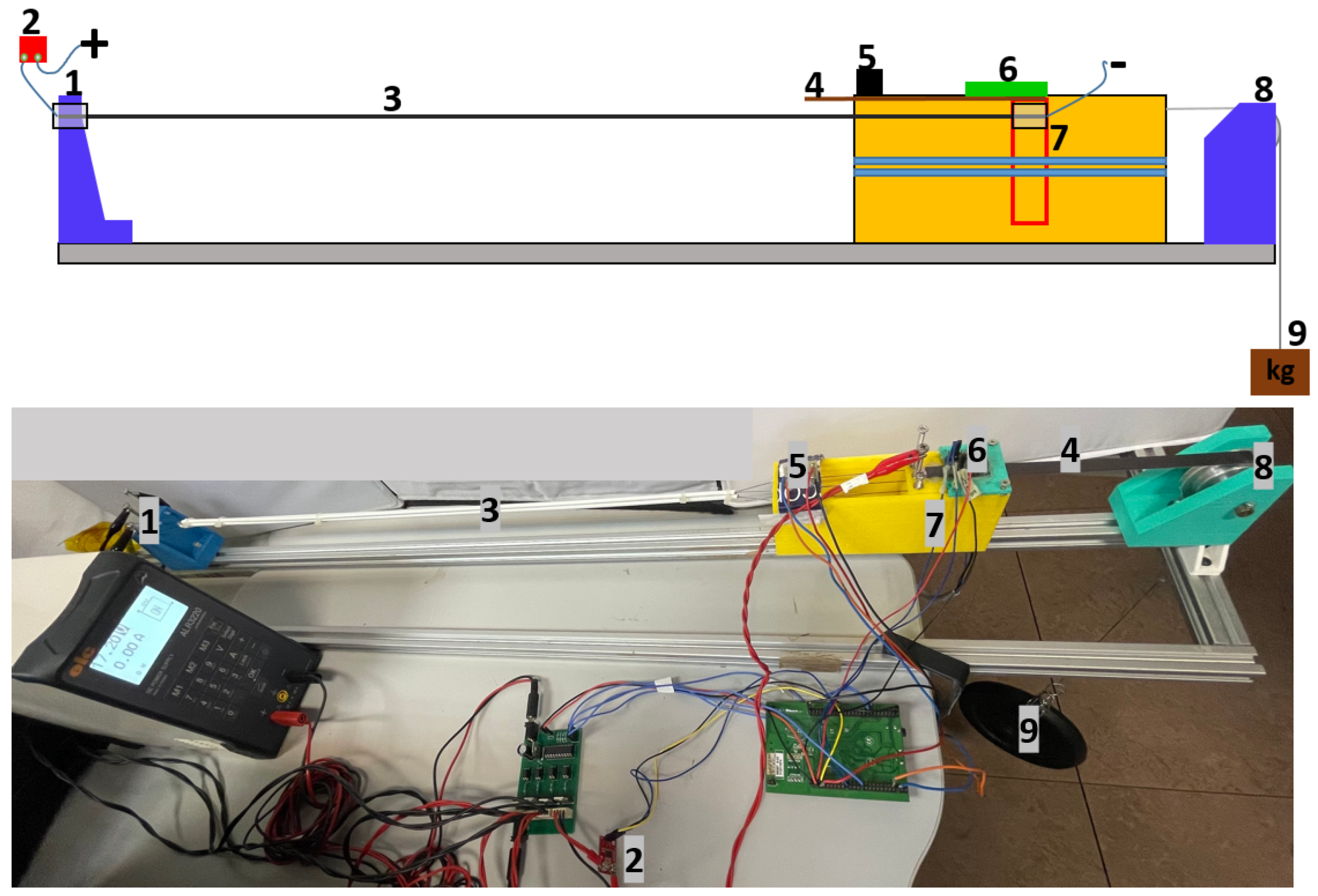
The test bench used in this work was composed of two subsystems: mechanical and electrical. The mechanical subsystem provided support for the SMA actuators fixing the SMA wires and support for the sensors, pulley, axis, and the rest of the elements necessary for operation. The structure of the test bench is shown in
Figure 1 where:
Element 1 represents the fixed ends of the SMA wires. These terminals help to fix the SMA on the test bench and are used as connectors for the power supply.
Element 2 is the current sensor based on ACS723 manufactured by SparkFun Electronics (Niwot, CO, USA) [
28], using an analog interface and have a sensing range of 5 A.
Element 3 represents the SMA-based actuator, which can have different dimensions and configurations and is described in
Section 2.3.
Element 4 is a magnet component necessary for the position sensor.
Element 5 is the temperature sensor, infrared thermometer MLX90614, manufactured by Melexis (Ypern, Belgium) [
29]. This is used with an
interface and has a resolution of 0.02
C.
Element 6 is the position sensor based on the Hall effect, NSE5310, manufactured by ams AG, (Styria, Austria) [
30], which uses an
interface and has a resolution of 0.488
m.
Element 7 is the movable part of the test bench. This element is moved by the SMA actuator contraction and permits the measurement of the displacement.
Element 8 consists of a pulley fixed to the test bench, so that a standard wire (fishing wire from Caperlan [
31] with a maximum payload of 20 kg) can move properly.
Element 9 represents the payload that can be attached and displaced by the actuator.
From the schematic in
Figure 1, the SMA actuator was not directly connected to the payload, as there was a moving part in the middle. The end of the actuator was anchored to the mobile element of the test bench (Element 7), and this was connected to the load through a standard wire (Element 8). In this way, the displacement produced could be accurately measured using a Hall-effect sensor (Element 6).
The electronic subsystem was composed of a 32 bit microcontroller, a power electronics stage, and various sensors: position, current, and temperature (the temperature sensor was not used in this work). The microcontroller was based on STM32F407 from STMicroelectronics
® (Geneva, Switzerland), which can be fully programmed with MATLAB/Simulink
® (MathWorks, Natick, MA, USA) [
32]. The power electronics stage was based on a MOSFET transistor (STMicroelectronics STP310N10F7, Geneva, Switzerland), which worked as a commutation circuit and amplified the control signal, the pulse width modulation (PWM), generated by the controller. This device was located outside the test bench and connected to the terminal units of the SMA-based actuator.
2.3. Actuator Configurations
In this work, the Joule effect was used to heat the SMA wires: the electrical energy was transformed into thermal energy. After this process, this thermal energy was transformed into mechanical energy. This type of material can be found in different shapes—wires, ribbon, springs, etc.—according to its composition with different activation temperatures. In this work, SMA wires from Dynalloy (Irvine, CA, USA). [
33] with 70 and 90
C activation temperatures were used. The composition of these alloys is typically 55–56% nickel and 44–45% titanium. The characteristics of these wires are presented in
Table 1.
In this work, the most common configurations of SMA actuators, which we integrated into different devices, were analyzed. These configurations of SMA-based actuators were tested and analyzed in relation to the total power consumption and the total displacement. The performance of a servomotor was analyzed in comparison with that of SMA-based actuators. These configurations were:
uncovered SMA wires: actuators with one or more wires;
SMA-based actuators with Bowden cables, which offer the advantage of flexibility; and
a double actuator, which, with the same dimensions as the simple actuator, almost doubles the actuator displacement.
Actuator with Bowden cables are composed of one or more inner SMA wires (in this work, only one SMA wire), surrounded by a PTFE tube, and a Bowden cable in the external layer. Terminal elements are added, which, in this work, were fixed to the test bench. The Bowden cable configuration leads the SMA wires and transmits the force [
34].
The characteristics of the actuator configurations that were analyzed were:
Actuator 1
- −
Only one SMA wire, no Bowden cable, and PTFE tube.
- −
Characteristics of 1 m length, 0.51 mm diameter, and 90 C activation temperature.
- −
With this diameter, the actuator can exert a nominal force of 35.6 N (with a lifetime of tens of millions of cycles), and can work to a maximum force of 118 N but the lifetime of the actuator decreases to hundreds of or a few thousand cycles.
Actuator 2
- −
Only one SMA wire, no Bowden cable, and PTFE tube.
- −
Characteristics of 0.8 m length, 0.51 mm diameter, and 90 C activation temperature.
- −
The force of this actuator is the same as that of Actuator 1.
Actuator 3.
- −
Only one SMA wire, with Bowden cable, and PTFE tube.
- −
Characteristics of 1 m length, 0.51 mm diameter, and 90 C activation temperature.
- −
The force of this actuator is the same as that of Actuator 1.
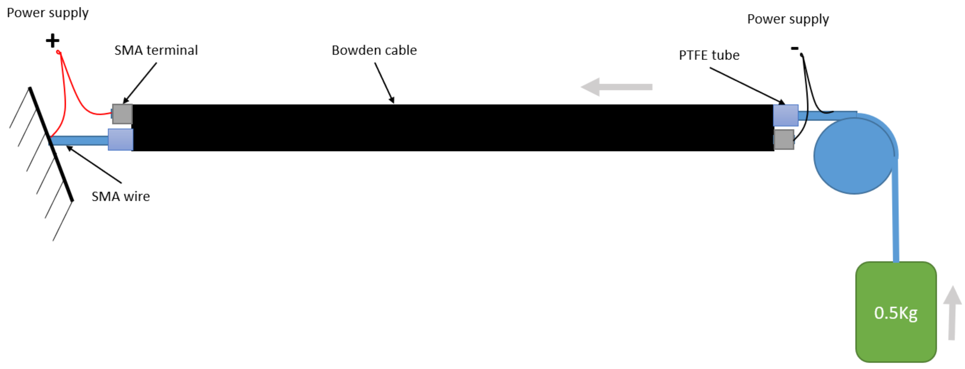
Actuator 4: The double actuator formed by two SMA wires with 0.51 mm diameter and 90
C activation temperature. These two SMA wires are introduced individually in two PTFE tubes to avoid electrical short-circuit and, after that, in a Bowden tube. The configuration of the double actuator is shown in
Figure 2.
The double actuator with the same length as Actuator 3 (l), composed by two SMAs, has the following working principle: the first SMA wire end is attached to the fixed part and the other end to the Bowden cable. The second SMA wire is fixed with one end to the Bowden cable and the other end to the mobile weight (payload), which needs to move. When the first wire is activated, it contracts and displaces the weight together with the Bowden cable and the structure of the second actuator. When the second wire is activated, the payload is moved together with the first wire, obtaining almost double the displacement compared with Actuator 3.
If a simple actuator (Actuator 3) has a length
l, according to the Dynalloy datasheet [
33], after its transformation, it presents a displacement of 4% of the total length (Equation (
7)), where
d is the displacement and
l the wire length.
The double actuator needed to have the same length as the simple actuator to compare the displacements; in this case, the lengths of the SMA wires were calculated according to Equations (
8)–(
10):
where
is the length of the SMA wires of the double actuator.
where
is the displacement of the double actuator (Actuator 4).
According to Equation (
10), Actuator 4, with a length
l, can obtain a 7.69% displacement compared with Actuator 3 with the same length and 4% displacement.
Actuator 5
- −
Three SMA wires without a Bowden cable and PTFE tube.
- −
Characteristics of 1 m length, a wire diameter of 0.31 mm, and 90 C activation temperature.
- −
The nominal force of this actuator is 38.4 N.
Actuator 6
- −
Three SMA wires without Bowden cable and PTFE tube.
- −
Characteristics of 1 m length, a wire diameter of 0.31 mm, and 70 C activation temperature.
- −
The nominal force of this actuator is the same as that of Actuator 5, 38.4 N
Actuator 7: A linear servomotor, Miniature Linear Motion Series L16 manufactured by Actuonix Motion Devices, Unit 201-1753 Sean Heights Saanichton, BC, Canada [
35], weighing 0.074 kg, with a maximum displacement of 0.1 m, 100 N peak force, and 60 dB audible noise.
A summary of these configurations is presented in
Table 2. Here, the SMA wires refer to the number of wires for each actuator, the diameter represents the diameter of each wire, the length refers to the total actuator length, the temperature represents the activation temperature for the wire, and the nominal force is the nominal actuator force.
2.4. Control Strategy
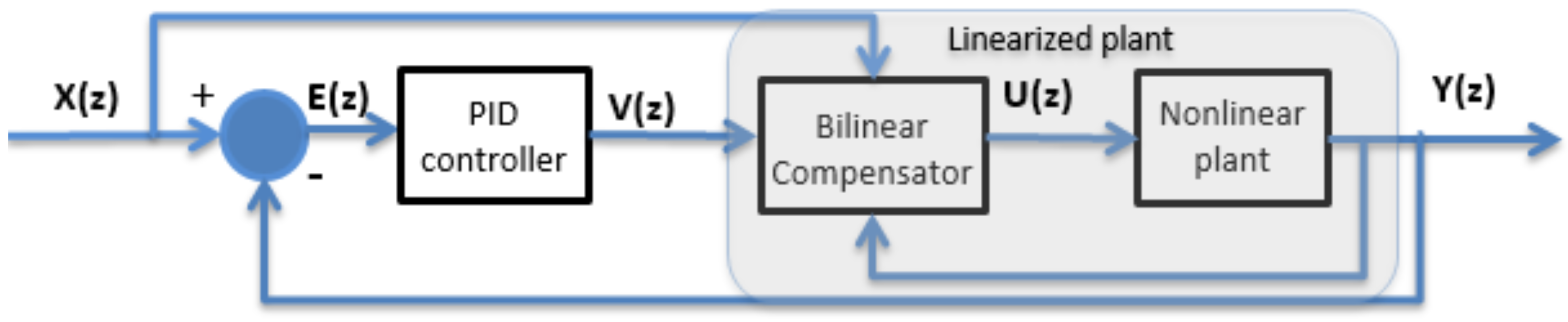
The control algorithm used in this work is based on the work of Copaci et al. [
16]. A bilinear proportional integral derivative (BPID) controller was used to compensate for the non-linearities of the SMA-based actuator. This consists of a standard PID controller cascaded with a bilinear compensator. A simplified scheme of this controller is presented in
Figure 3.
The equations that describe this controller are composed of the bilinear compensator (Equation (
11)) and the PID controller (Equation (
12)):
where
is the reference,
is the position sensor signal,
is the control signal generated by the PID controller,
is the control signal rectified by the bilinear term, and
is the bilinear gain. More information about how this formula is deduced can be found in [
36].
The PID controller was used to generate the control signal, the pulse width modulation (PWM) signal
, which sends modulated current to the actuator according to:
where
is the PWM duty cycle,
is the proportional gain,
is the derivative gain, and
is the integral gain.
The controller gains were identified using the trial and error method, observing the actuator response (Actuator 1). The values of the gains are shown in
Table 3.
The same control algorithm with the same gain parameters was used for all actuators except Actuator 7, the servomotor. The control signal is an important parameter that needs to be considered in practice as it direct influences the dynamics of the systems and, thereby, its lifespan. For the proposed actuator configurations, the behaviors in the heating stage are similar, which led to the decision to maintain the same gain parameters for BPID control for all configurations. In this way, the different gains parameters would not affect the power consumption, and permit analysis and comparison of the electrical efficiency of the actuators.
The driver used for Actuator 7, the servomotor, was a linear actuator control board from Actuonix Motion Devices. This servomotor was controlled by a PD controller with the aid of Linear Actuator Control (LAC) software from Actuonix, which allowed us to tune the controller according to a step position signal. The data were acquired as the values from the current sensor with a STM32F407 microcontroller manufactured by STMicroelectronics®, Geneva, Switzerland, in MATLAB/Simulink®.
2.5. Test Setup
The different actuator configurations presented in
Section 2.3 were tested and analyzed from the point of view of power consumption and other characteristics such as total displacement. During all tests, the payload of the actuators was 3 kg and the voltage of the power supply was set according to the SMA characteristics presented in
Table 1. The running time of each test was set to 420 s. This period is considered sufficient for error stabilization (the residual heat is constant in the cooling process) according to the sinusoidal reference, which was experimentally verified. In Test 4, where the SMA was compared with the servomotor, the total period was 17 s. The reference was a sine wave with a frequency of 0.0668 Hz. With this reference, the SMA actuators needed to lift the payload in 7.5 s and another 7.5 s to descend the payload. The necessary cooling time for the majority of the SMAs used in this study is more than 14 s (
Table 1); during the descending movement with the sinusoidal reference, the actuator is activated to slow down the payload. Another reason for choosing this frequency was our goal of introducing these actuators in rehabilitation devices, using an acceptable frequency for rehabilitation therapies. The ambient temperature was 22
C.
2.5.1. Test 1: Energy Consumption vs. Wire Length
The objective of this test was comparing the energy consumption to achieve the same displacement with different-length wires (
Table 4), which implies different displacement percentages. Firstly, Actuators 1 and 2 were compared. These actuator configurations have the same diameter and activation temperature but different lengths.
This test was conducted as follows: both actuators were displaced with the same reference sinusoidal amplitude wave to provide a determined maximum displacement. This corresponded to different percentages of contraction for every wire (
Table 5) and the energy consumption was calculated from the current measured.
2.5.2. Test 2: Effect of Bowden Cable
In this test, all actuators (
Table 6) had the same length, but we analyzed the effect of the Bowden cable and the double actuator performance against the simple configuration.
The second test was conducted to compare Actuators 1, 3, and 4. Similar to the first test, the response of the three actuators was analyzed when the reference of the actuators was a sine wave with an amplitude of 29.28 mm.
2.5.3. Test 3: Effect of Activation Temperature
In this test, the effect of activation temperature was analyzed. The third test was used to compare Actuators 5 and 6 (
Table 7) with the response to the same input, the sinusoidal wave. These actuator configurations have the same diameter and length but different activation temperatures. In this case, the Bowden cable was not used in any of the actuators.
This test could be discussed and analyzed according to the previous configurations. We also discussed the comparison between these two actuators’ configurations and Actuator 1 with only one SMA wire.
2.5.4. Test 4: SMA-Based Actuator vs. Servomotor
Test 4 consisted of a comparison between Actuators 1 and 7 (
Table 8), the servomotor. In this case, the reference was a step signal with an amplitude of 29.28 mm for Actuator 1 and 80 mm for Actuator 7. The performance of an SMA-based actuator was compared with a servomotor of similar performance.
3. Results and Analysis
3.1. Results of Test 1
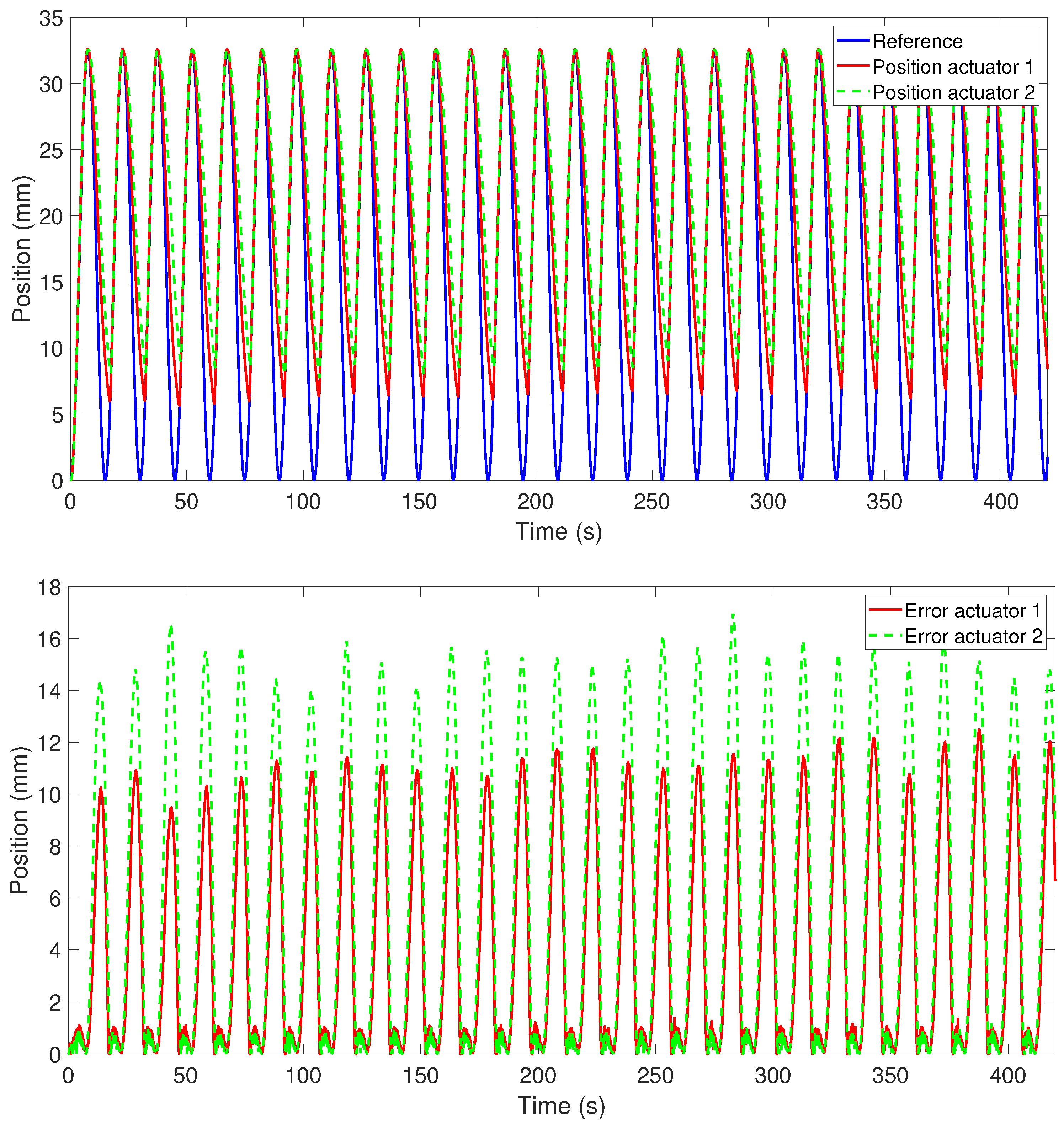
The position response of Actuators 1 and 2, which had the same characteristics but different lengths, when the reference was a sinusoidal wave with a frequency of 0.0668 Hz and an amplitude of 32.5335 mm, is presented in
Figure 4. This response was obtained in a closed loop with a BPID controller (the controller simple time was 0.002 s). As shown in the lower part of
Figure 4, with this controller, the error was the lowest in the heating stage of the SMA-based actuator (around 2%), but the error increased considerably in the cooling stage to around 30% for Actuator 1 (the longest) and to 45% for Actuator 2 (the shortest). This large position error in the cooling stage was due to the necessary time to cool the actuator in ambient temperature to recover its original form. No forced cooling source was used in this experiment. The position response can be improved by working with the actuator at low frequency or changing the wire diameter to a smaller one (according to
Table 1, the cooling time decreases). In the two actuators (Actuators 1 and 2) with the sine reference with one cycle every 15 s, the error was relatively stable over time. We concluded that, by using an over-dimensioned actuator in length (Actuator 1) but with the same diameter, the position error decreases.
In terms of position response, both actuators were tested with different references (the amplitudes described in
Section 2.5). Although the position error in the cooling stage for Actuator 1 (the longest) was less than that of Actuator 2 (the shortest), the difference between the two errors decreased with decreasing amplitude of the sinusoidal wave.
To analyze the energy consumption, the current that passes from the SMA wire was measured with the current sensor presented in
Section 2.2, and the voltage was calculated according to the wire’s datasheet [
33].
The electrical energy of the SMA-based actuators was calculated integrating the electrical power, Equation (
13), in the time interval
, where
U is the voltage,
i is the current,
is the initial time, and
is the time when the experiment is completed.
The electrical power and the electrical energy of Actuators 1 and 2 during the tests presented in
Section 2.5 are summarized in
Table 9. The electrical power is presented as the average during the 420 s of the experiment and the electrical energy is the total energy calculated with Equation (
13) for 420 s.
According to the results presented in
Table 9, when the actuator does not work at a maximum strain (maximum contraction), the electrical energy consumption is less for the shorter actuator. This statement is not valid when the actuator needs to work with more than 3.7% (approximately) of its strain. The results demonstrated that it is better to over-dimension the actuator and work at a lower percentage of strain to reduce electrical energy consumption. This makes sense because in the austenite phase, the last phase of contraction, the wire needs a higher temperature change, obtaining less displacement compared with another zone of contraction (less than 3.7%) between the martensite and austenite phases. This can be observed in
Figure 5, where the electrical power is represented according to the sine wave amplitude for the two actuators (long and short).
Therefore, the position error is reduced by using an oversized actuator, in which a lower percentage of contraction is needed for the same displacement. However, the electrical energy consumption is lower for shorter actuators, if it is not necessary to achieve the maximum percentage of contraction (greater than 3.7%).
3.2. Results of Test 2
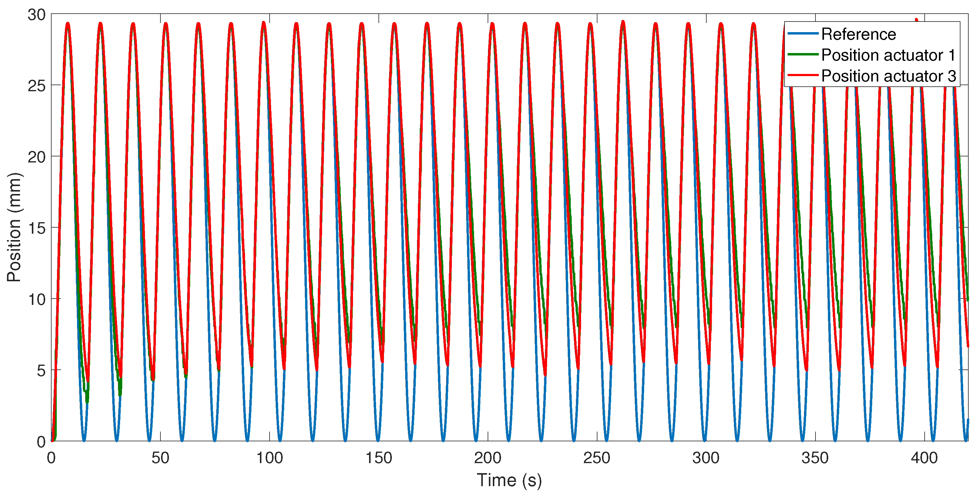
The response of the position of Actuator 3 (the same length and characteristics as Actuator 1 but with a Bowden cable) to the sine wave reference (with an amplitude of 29.28 mm and frequency of 0.0668 Hz) presented an error of around 34.3% in the cooling stage when working continuously for 420 s (
Figure 6). In the first cycles, the actuator with a Bowden cable better recovered its initial position (cooling faster) compared with the actuator without a Bowden cable (when the reference was the same sinusoidal wave). This occurred due to the Bowden cable, which, in the first cycles, is cold and helps to dissipate the heat. For continuous work, after some cycles, the Bowden cable accumulates heat and the actuator’s cooling slows. The Bowden cable provided the advantage of actuator flexibility, which Actuators 1 and 2 did not have.
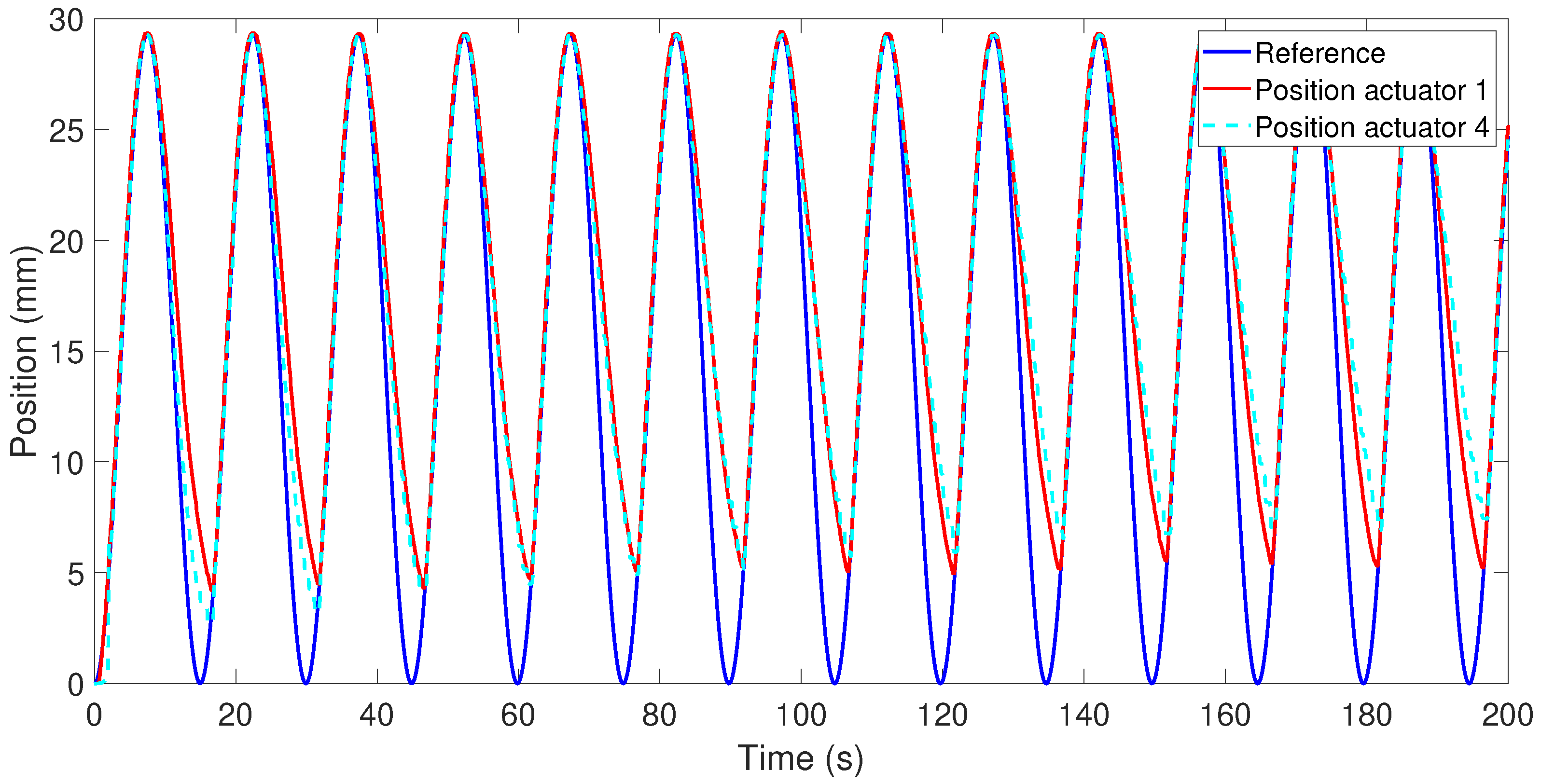
The position response of Actuators 1 and 4 (the double actuator), when the reference was a sine wave with an amplitude of 29.28 mm and frequency of 0.0668 Hz, is shown in
Figure 7. The same effect caused by the Bowden cable was present in this test: in the first cycles, the position error in the cooling stage was less for Actuator 4 compared with Actuator 1, and greater in the rest of the cycles.
Electrical power and energy consumption were higher for Actuator 3 (with Bowden cable; 8.1 W and 3401 J, respectively) compared with Actuator 1 (4.47 W and 1880 J, respectively) for 420 s. This high electrical power consumption is largely due to the first cycles of work where the heat is quickly dissipated. For actuators with a Bowden cable and multiple wires, the electrical power consumption is less when the wires are in the same Bowden cable compared with the case where each wire is in an independent Bowden cable, but this implies that the position error will be greater [
15].
The electrical power and energy consumption of this actuator (Actuator 4) in 420 s were found to be 8.6488 W and 3632.5 J, respectively. Compared with Actuators 1 and 3 (with Bowden cable), the electrical energy consumption is superior as two SMA wires needed to be heated. However, for its operation, this actuator needs to be in a straight linear position and is less efficient in terms of electrical power consumption. The advantage compared with Actuators 1 and 3 is the double displacement using the same length of actuator.
3.3. Results of Test 3
SMA wires, in addition to the material, can differ in diameter and temperature of activation. Actuators 5 and 6 had three wires each with a diameter of 0.31 mm and 90 and 70 °C activation temperatures, respectively. The nominal force of this SMA wire is 12.8 N, which is 38.4 N for each actuator, being approximately the same force as actuators with only one wire 0.51 mm in diameter.
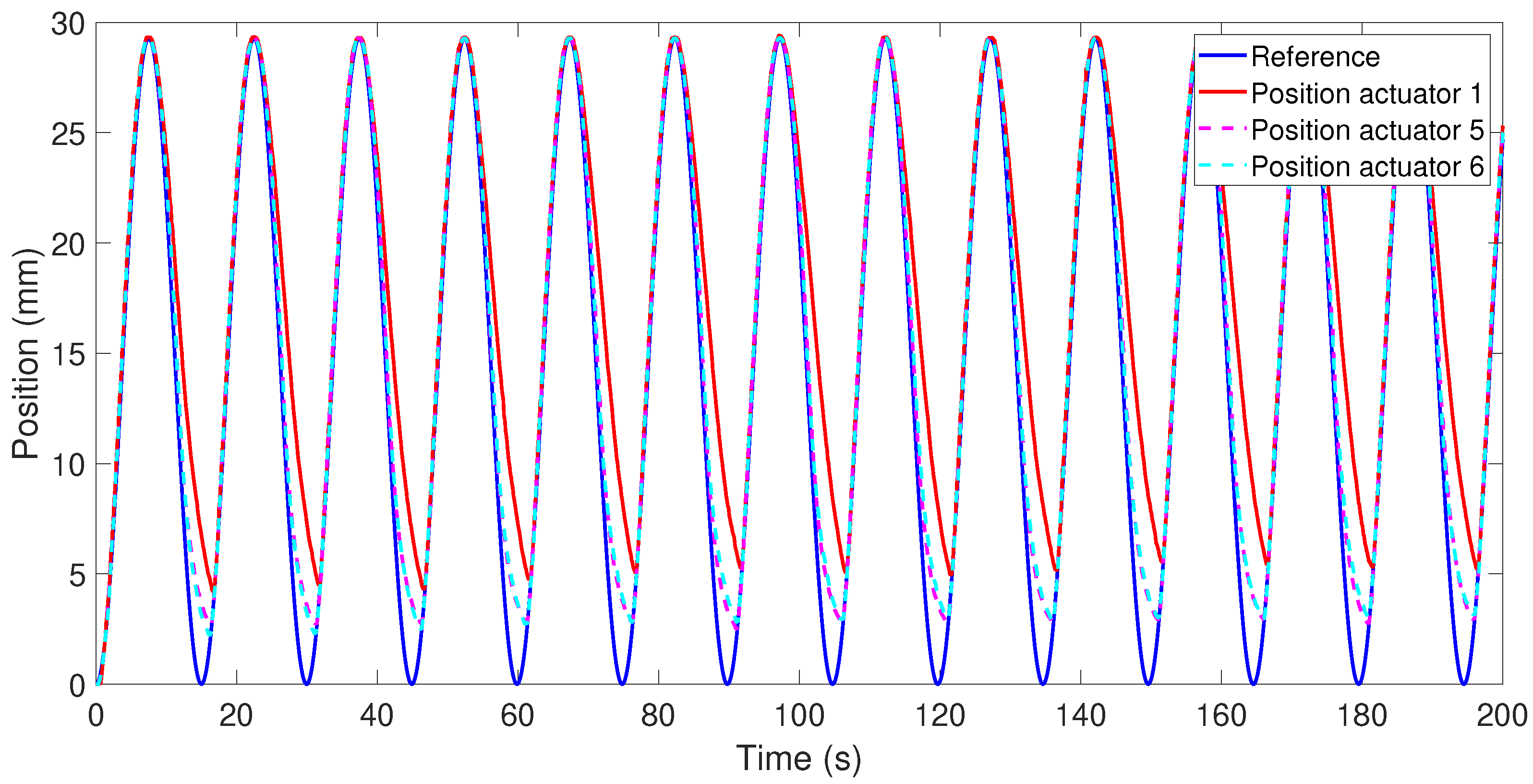
Figure 8 depicts the response of Actuators 1, 5, and 6 when the reference signal was the same sine wave and each actuator displaced a payload of 3 kg.
The responses of Actuators 5 and 6 were very similar: the average position error of Actuator 5 was 1.2142 mm and that of Actuator 6 was 1.3205 mm, which are considerably less than the average error for Actuator 1 at 3.3115 mm. The position error difference between Actuators 5 (90 °C) and 6 (70 °C) is due to the temperature of activation. With activation at 70 °C, it takes longer to recover the initial form. Compared with Actuator 1 (only one SMA wire with a diameter of 0.51 mm and 90 °C activation temperature), Actuators 5 and 6, formed by multi-wires, produced a better response in the position due their small diameter in the cooling stage and faster recovery to their initial form.
The electrical power consumption of Actuators 1, 5, and 6 is presented in
Figure 9 for 200 s, although it was calculated for 420 s to enable comparison with the other actuator configurations. The electrical power consumption for Actuator 5 was 9.5585 W, and it was 7.6263 W for Actuator 6. Actuator 6, due to lower temperature activation, was more efficient from an energy point of view compared with Actuator 5. Nevertheless, both actuators consumed more energy than Actuator 1. The electrical energy consumption during 420 s for Actuators 5 and 6 were 4014.5 and 3632.5 J, respectively.
The multi-wires actuators responded better in the cooling stage; therefore, they had a lower position error, but were less efficient in terms of energy.
3.4. Results of Test 4
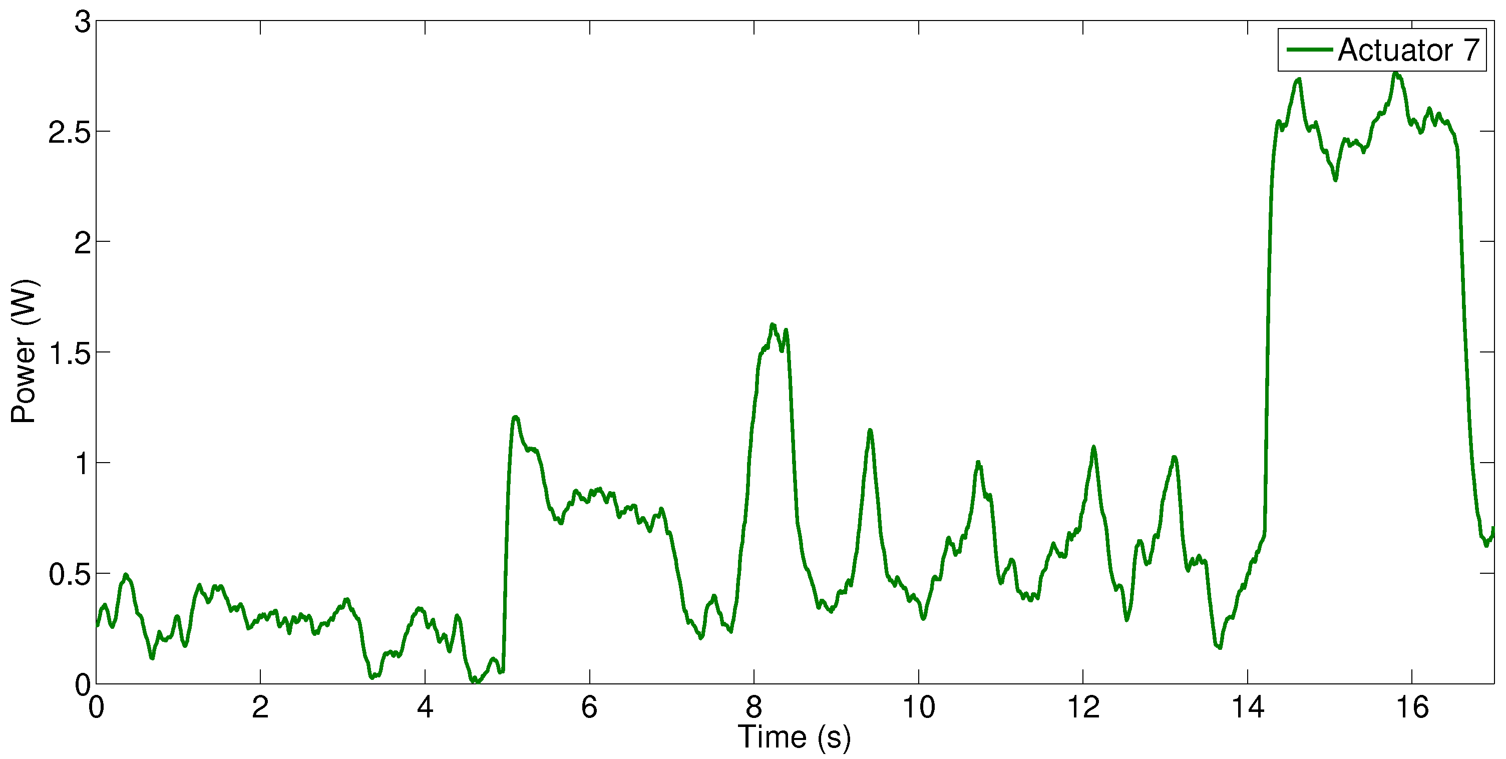
Actuator 7, a servomotor, was tested with a payload of 3 kg and a step reference (from 0 to 80 mm and return). During this test, the electrical power consumption, as presented in
Figure 10, and electrical energy for 17 s was measured: 0.8102 W and 13.77 J, respectively. Actuator 1 was tested with a step reference (29.28 mm) and a 3 kg payload. During its displacement, the weight was lifted, maintained at 29.28 mm for 5 s, and then returned down in a total of 17 s. During this time, the electrical power consumption and total energy were 4.31 W and 73.381 J, respectively.
These results show that, for the same task, the servomotor has an electrical energy consumption around 5.5 times higher compared with the SMA actuator. However, this is an approximation for a specific case, and it may vary according to the application in which the actuator is integrated.
3.5. General Overview
SMA actuators are a suitable choice in many applications where conventional actuators present limitations such as weight, noise, and velocity. Although SMA actuators present certain limitations, these can be minimized using actuator design (configuration) when selected for a specific application. According to the results obtained in our experimental tests, a general overview can be provided:
The diameter of the SMA wire influences the actuator’s working frequency. The smaller is the diameter, the lower is the thermal inertia, which implies a high work frequency (due to the reduced cooling time). If the required force is greater than that provided by only one wire, many wires in parallel configuration are needed to achieve this force or only one wire with greater diameter (greater force). For a high work frequency, the parallel configuration is better, but this configuration increases the power consumption. Another challenge with the parallel configuration is maintaining the same tension in each wire.
The length of the wire is an important factor when an SMA-based actuator is designed. The total length of the wire can influence the total power consumption and the position error when the actuator works with a cooling time less than that proposed by the manufacturer. With the tests, we demonstrated that, although the SMA wire from Dynalloy permitted more than 4% strain, it is more energetically efficient to work with only 3.7% with an over-dimensioned length of wire. The position error is less if the SMA wire is over-dimensioned.
The Bowden cable provides the advantage of actuator flexibility. If the actuator with a Bowden cable works for a few cycles, depending on the frequency, it produces a better response in the position (the error is less than without a Bowden cable). Conversely, if the actuator works for various cycles, the heat is accumulated in the Bowden cable after a few cycles and its response in the position is deficient. The power consumption of the actuator with the Bowden cable is higher.
The activation temperature of the SMA actuator permits their use in different environments. Using an SMA with high activation temperature cools more quickly in ambient temperatures. This improves the work frequency of the actuator and the position response, but it increases the power consumption. The low temperature activation wires are more electrically efficient.
Table 10 provides the final results with the different actuator configurations.
4. Conclusions
SMA-based actuators are excellent candidates for robotics applications, eliminating gears, housing, boxes, bearings, and so on, with reduced noise level, lower cost compared with other actuators, and permit work in different environments including corrosive environments. The results of the experiments demonstrate that the efficiency of an SMA-based actuator depends on its configuration.
Using an over-dimensioned actuator (wires), the electrical efficiency and the position response of the actuator in the cooling stage (when recovering its original form) are improved.
It is convenient to use a Bowden cable actuator to obtain flexibility, which is an advantage for flexible robotics or other similar applications, but, if the wire is held for a long time at elevated temperature (sufficient to elevate the temperature of the Bowden cable), the actuator performance in terms of position response in the cooling stage will decrease. If the actuator does not maintain a high temperature for a long time, the Bowden cable will help to dissipate the heat, improving the behavior of the actuator in terms of position response. Unfortunately, the Bowden cable negatively affects the electrical efficiency of the actuator.
The double actuator offers the advantage of double displacement compared with a simple actuator (Actuator 1), but it decreases the performance in terms of position (in the cooling stage) and electrical efficiency.
Multi-wires actuators improve the position response of the actuator, being able to work at higher frequencies, but the electrical efficiency of this type of actuator is worse.
The last test of this study, in a specific case, demonstrated that the electrical efficiency of an SMA wire actuator can be around 5.5 times worse, but this is compensated for by the advantages of the SMA actuators, where the conventional actuators present limitations.


