Article

Design and First Operation of an Active Lower Limb Exoskeleton with Parallel Elastic Actuation

1
Helmholtz Institute for Biomedical Engineering, RWTH Aachen University, Pauwelsstr. 20, D-52074 Aachen, Germany
2
Department of Mechanical Engineering, Institute of Mechanical Design, Tsinghua University, Shuangqing Road 30, Beijing 100084, China
*
Author to whom correspondence should be addressed.
Submission received: 12 March 2021 / Revised: 3 April 2021 / Accepted: 6 April 2021 / Published: 8 April 2021
(This article belongs to the Special Issue Feature Papers to Celebrate the SCIE Coverage)

Abstract

:
The lower limb exoskeleton investigated in this work actively supports the knee and hip and is intended to provide full motion support during gait. Parallel elastic actuators are integrated into the hip joints to improve the energy efficiency in gait. The prototype was tested in sit-to-stand and gait trials, in which the actuators were cascade-controlled with position trajectories. The compliant actuation of the hip in gait experiments proved to be more efficient; the peak torque was reduced by up to 31% and the RMS power was reduced by up to 36%.

1. Introduction

Motion support for the lower limbs of patients suffering from limited motor function is an active field of research. Consequently, the development of exoskeletons has been greatly advanced in recent years. In the following, various lower limb exoskeletons and, subsequently, compliant actuators are presented to provide an overview of the state of the art. The exoskeleton prototype introduced in this paper is intended to be used for paraplegic patients in the long term. Therefore, the overview focuses on related applications. Table 1 summarizes eight exoskeletons for the support of the lower extremity. All presented exoskeletons presented in Table 1 provide hip and knee actuation with electric motors but differ in the power ratings, gait velocity and usage. Except for the REX exoskeleton (Rex Bionics Ltd., Auckland, New Zealand), all other systems require auxiliary equipment, such as crutches [1]. This ability of hands-free operation results from the low gait velocity of 0.1 m/s [2]. The Lokomat has the highest limitation in terms of free walking, as it is fixed to a treadmill [3]. Both the peak torque and the continuous torque ratings are important for the operation of an exoskeleton. Peak torques are particularly relevant for non-cyclic tasks, such as sit-to-stand, while the nominal values are significant for continuous gait operation. Exoskeletons with requirements analogous to this prototype weigh between m e x o = 17.7 kg and 50 kg [1,4]. The usual maximum weight including the patient in this motion support application is assumed to be 100 kg [2]. The maximum torque is often limited by the mechanical components. The prototype of Zhang et al., for instance, can withstand a maximum transmission torque of 110 N·m due to the gearbox selected [5]. This matches the maximum peak torque specified for other exoskeleton prototypes, such as the Mina exoskeleton [6]. The peak torques realized are in some cases far higher than required. The requirement, for instance, defined for the Mindwalker exoskeleton is 150 W but the motor of the prototype can provide about six times that output [7]. The analysis of the systems presented will be used to substantiate the design requirements of the hardware proposed.
Regarding the topology of the actuators of the motion support systems, it is apparent that conventional rigid coupled actuators (RA) are used to a large extent. In our overview, only the Mindwalker prototype contains serial elastic actuators (SEAs), which introduce a compliant element between the actuator and load to decouple the robot from the load for smoother human–machine interaction [7]. The serial compliance in the mechanical design, furthermore, causes a bandwidth limitation of the system, which has to be compensated by additional design modifications, such as the capability of stiffening the elastic element [9]. However, in rehabilitation robotics, including applications where strong patient activity is not expected, for example, for paraplegics, rigid drives have often been used to date (see Table 1). In our work, we investigate the parallel elastic actuators (PEA) and postulate that the efficiency of such drives in cyclical motion tasks, such as gait, can be increased by employing an elasticity acting in parallel to the actuator (PE). In addition, there are clutched PEAs (CPEA), where the neutral position of the elasticity can be changed via a clutch. The different actuator topologies are summarized in Figure 1.
Mummolo et al. [10] and Masood et al. [11] proposed PEAs for assisting workers in carrying and lifting weights while reducing the actuator’s peak electrical torque and accelerating its reaction. Plooij et al. showed for cyclical tasks that the energy consumption could be reduced by up to 65%; however, this example is not from the field of rehabilitation robotics. A maximum energy saving of 73% was determined simulatively for an artificial periodic application for the same actuator [12]. Aftabi et al. [13] placed a bent leaf spring parallel to human hip joints to relieve hip muscles during running at 2.5 m/s. Employing treadmill experiments, they have shown that the metabolic cost was reduced by 8% using a PE. In a theoretical study, Wang et al. showed that an ideal PE can reduce peak flexion/extension torque and root mean square (RMS) power at the hip by up to 66 and 50% for gait velocities from 0.8 to 1.2 m/s, respectively. At the same time, no significant improvement in RMS power consumption or peak torque during flexion/extension of the knee joint in gait was observed [14]. Therefore, The use of a PE seems to be well suited for supporting the flexion/extension of the hip joint in the human gait. We have shown in experiments on a test bench with a pendulum and a gait trajectory of the hip that the RMS power and the peak torque in this configuration could be reduced by 30% and 26%, respectively [15]. However, in that report, the verification of the improvement by a PEA in the human gait’s motion support was still pending. In another PEA prototype experiment, the load profile of the hip joint was realized by a second actuator. Li et al. demonstrated that a spring constant of 16 Nm/rad projected on the load side, optimized for 10 kg body weight, could reduce the RMS power by 10.3% in this simulated gait experiment [16]. A unique detail of this prototype is that the elasticity is located as a spiral spring between the motor and gearbox. In a subsequent paper, Li et al. simulatively determined a maximal reduction of the RMS power of 57.5% [17].
To summarize, the application of CPEA for the hip joint appears promising in terms of energy efficiency and peak torque. Motivated by these findings, the exoskeleton we present in this paper consists of two different actuators, an RA for knee flexion/extension and a CPEA for hip flexion/extension. Requirements are that the patient should be fully supported in gait and partially in sit-to-stand by the motion support system. The following paper starts with a section on the mechanical design of the actuators and exoskeleton (Section 2). The subsequent section introduces the experimental setup and the experimental procedure (Section 3). Finally, the results of the experiments are presented and discussed (Section 4), and a conclusion is given (Section 5).

2. Mechanical Design

In the following section, the design of the actuators and structure of the exoskeleton is introduced.

2.1. Design Requirements

The exoskeleton is designed for the support of paraplegic patients. This results in various requirements. The motion must be completely provided by the exoskeleton. In Germany, the average height of a person is about 1.8 m and the average bodyweight is 77 kg [18]. The length of the structure of the exoskeleton should be adaptable by 5% in both directions in order to be able to fit other users without exchanging parts. Wu and al. conducted a study to investigate the effects of a slow gait velocity on joint torques in healthy volunteers. Maximum normalized knee and hip joint torques of 0.27 and 0.34 Nm/kg, respectively, were found for a gait speed of 0.6 m/s. For a self-selected speed, the maximum hip and knee joint moments increase to 0.45 and 0.51 Nm/kg, respectively. For a maximum subject mass of 100 kg, this results in a nominal actuation torque required of about 50 Nm for both joint units [19]. Torque peaks of twice the nominal torque are to be expected. The range of motion in the sagittal plane for knee and hip joint during gait is φ 3 = 0 to 1.05 rad and φ 2 = −0.2 to 0.5 rad, respectively, where flexion is assumed to be a positive joint angle [20]. For sit-to-stand, the range of motion in the sagittal plane for the knee must be from 0 to 1.5 rad and for the hip from 0 to 1.8 rad [21]. Mechanical end stops are used to limit this movement range. The assisted gait’s maximum velocity is 0.8 m/s; thus, a minimum joint speed of 3.2 rad/s must be provided. The nominal power, including a safety factor of 1.2, should be at least P n = 150 W [22]. A target weight of 20 kg is set for the exoskeleton in relation to the designs summarized in Table 1, whereby the system is to be operated only stationarily with a fixed power supply. A battery must be used instead for future tasks that extend to sit-to-stand and walk on the treadmill. Regarding the topology of the actuators, CPEAs are planned for the hip and RAs for the knees. The ankle joint is not actuated. However, a support can be realized by the orthotic joints used via adjustable passive compliant components.

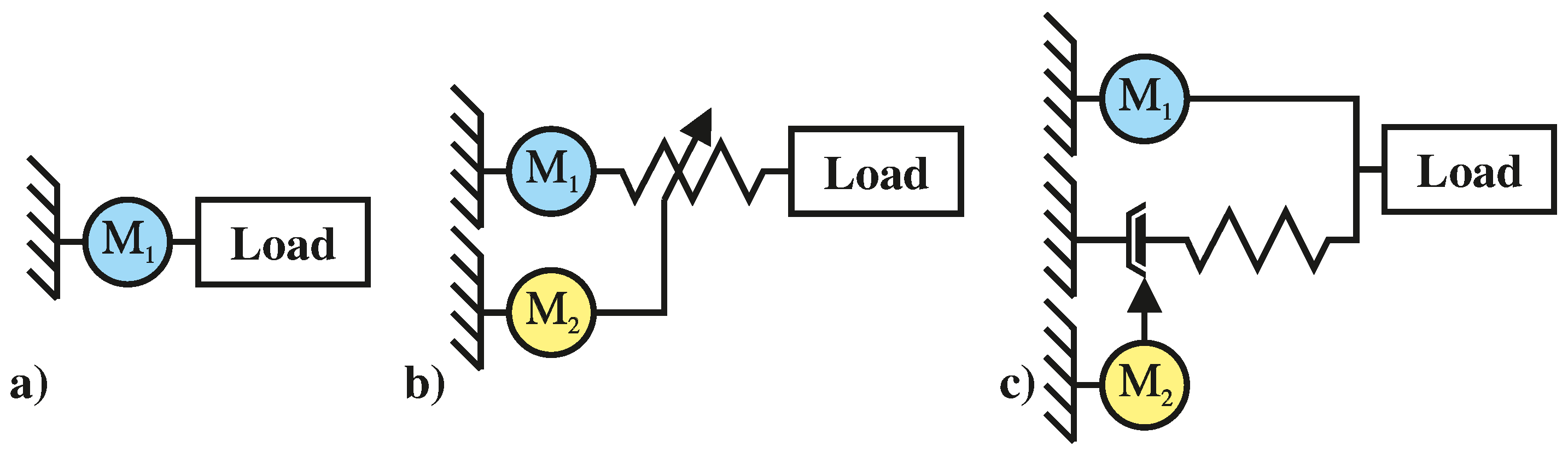
2.2. Actuator Design

Our exoskeleton, the L 2 EXO-PE, utilizes two different actuators: CPEAs for the hip joints and two RAs for the knee joints. The CPEA has already been presented in [15]. Both actuators, presented in Figure 2, share the same motor module, consisting of the motor shaft Actuators 10 00075 i001
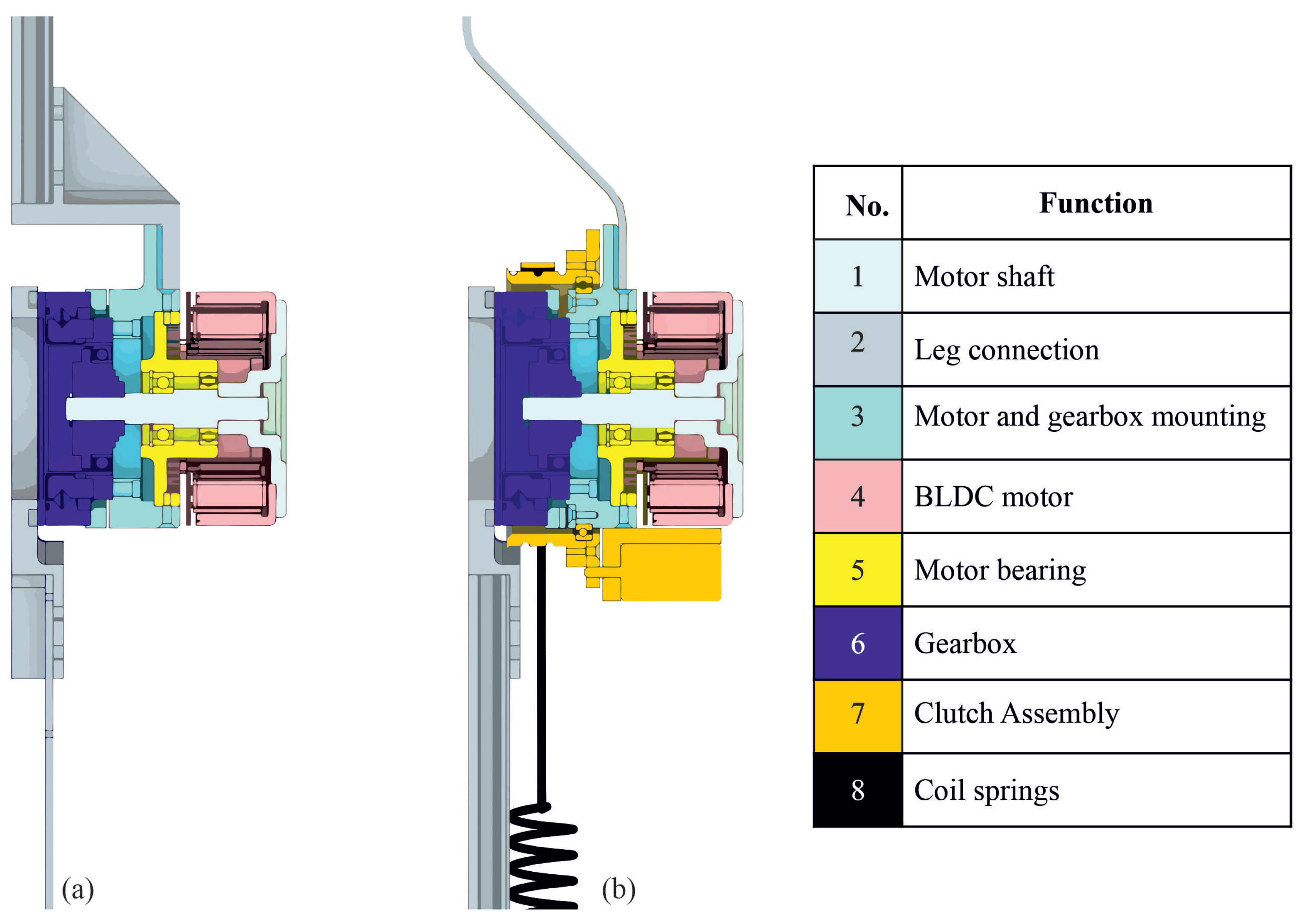
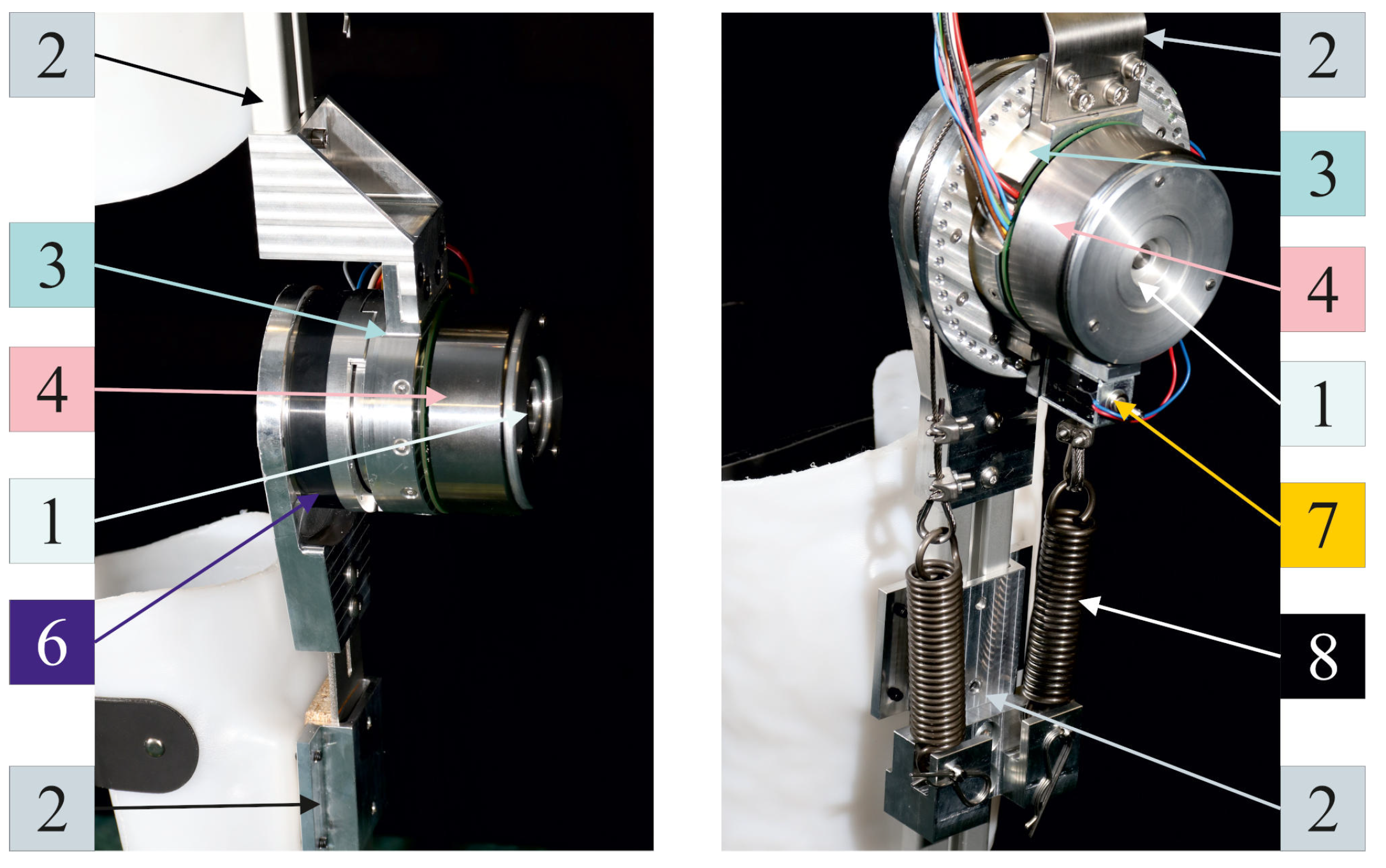
, the motor mounting Actuators 10 00075 i005 and an EC90 flat frameless motor Actuators 10 00075 i004 (Maxon Motor AG, Sachseln, Switzerland). A Harmonic Drive HFUS-2SO reduction gear (Harmonic Drive AG, Limburg an der Lahn, Germany) Actuators 10 00075 i006 with a transmission of 50/1 is used in both cases. The integrated cross roller bearing also serves as a joint bearing for the hip and knee. The limitation of the joint angles of the actuators is realized by a two-sided mechanical end stop, which acts between the gearbox output Actuators 10 00075 i006 and the gearbox mounting Actuators 10 00075 i003. Thus, the knee movement is limited from 0 to 2.1 rad, and the hip movement from −0.3 to 1.8 rad. The leg connection Actuators 10 00075 i002 is designed as a link between the reduction gear or motor attachment Actuators 10 00075 i003 and an aluminum profile. In the case of the CPEA, the gearbox mounting Actuators 10 00075 i003 is encased by a cable drum supported by a four-point bearing and can be locked by a 30 W switching magnet HMB-2218s Actuators 10 00075 i013 (Tremba GmbH, Hallbergmoos-Goldbach, Germany). Coil springs Actuators 10 00075 i014 are mounted on both sides of the cable drum Actuators 10 00075 i013 with a wire rope, thus, realizing a parallel elasticity. Four different coil springs, 1.82, 3.76, 5.49 and 11.96 N/mm, (Gutekunst + Co. KG, Metzingen, Germany) are selected to realize a spring rate of 10.2, 21.1, 30.8 or 67 Nm/rad, respectively, for the PE. The PE provides a maximum torque of τ m a x ≈ 21 N·m for the spring rate of 30.8 Nm/rad and a maximum deflection of 0.7 rad in both directions. A mass of 3 kg for one actuator was not exceeded for either the CPEA or RA.
The actuator specifications are summarized in Table 2. The actuators realized are shown in Figure 3; the 30 Nm/rad compliance is installed here, which acts directly on the output side of the gear box. The springs can be preloaded by moving the lower spring mounting.

2.3. Exoskeleton Design

The exoskeleton L 2 EXO-PE, as shown in Figure 4, is equipped with four actuators, two CPEAs Actuators 10 00075 i007
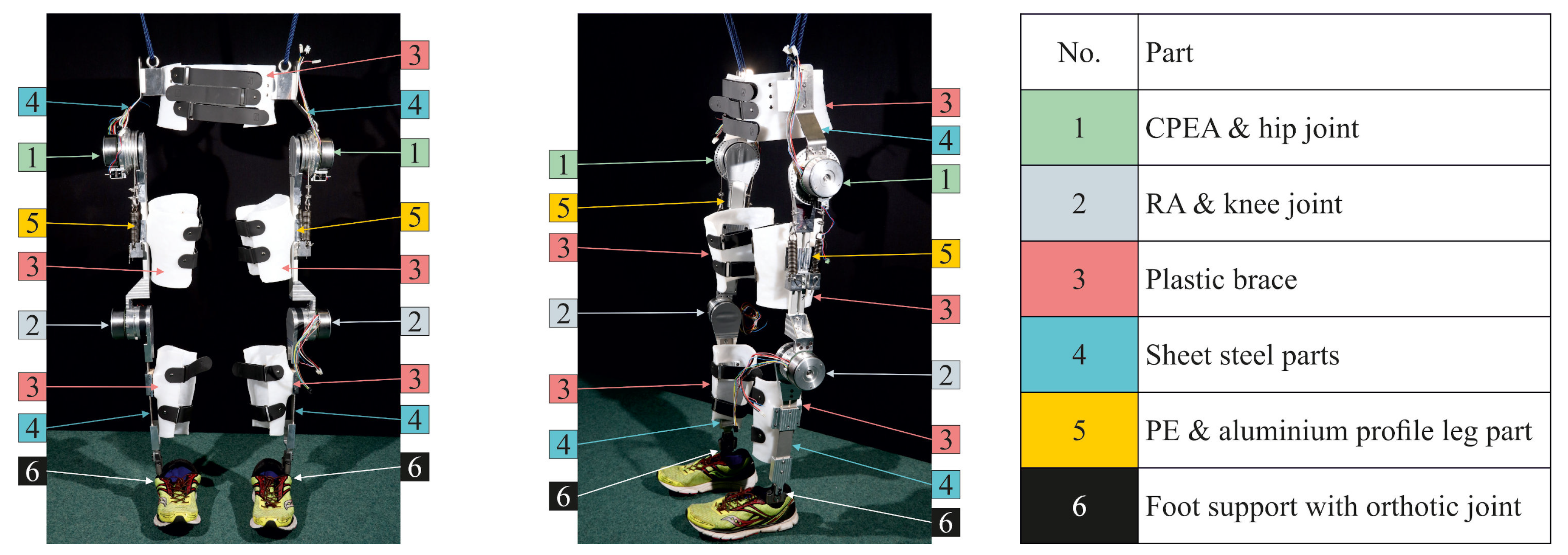
, each as a hip joint, and two RAs Actuators 10 00075 i008, each as a knee joint. Thus, only the hip joint has a parallel stiffness, which is mounted on the exoskeleton’s thigh part. The thigh Section Actuators 10 00075 i011 consists of an aluminum profile (item Industrietechnik GmbH, Mühlhausen, Germany). The linking parts for the lower leg and hip part Actuators 10 00075 i010 are made of cold formable sheet steel (1.4301). These sheet metal parts can be adapted to the anatomy of a subject in the frontal plane to fit individual knock-knees or bow legs. The thighs, lower legs and hip parts are fitted to a test person size of l B o d y = 1.81 m. The distance from the ankle to the knee joint l 1 and from the knee to the hip joint is l 2 = 430 mm each. The length of the lower leg, thigh and hip links can be modified by ±20, ±22 and ±13 mm, respectively. This adjustment would correspond to a height range of l B o d y = 1.72–1.90 m [23]. Other connecting links can be installed for further adjustments.
The shells for thighs, femurs and hips are formed from 4 mm thick polyethylene plates Actuators 10 00075 i009 (Streifeneder KG, Emmering, Germany). The shells are fastened with hook-and-loop tape, which is attached to the shells with 4 mm rivets. The foot part Actuators 10 00075 i012 is made of carbon fiber and is equipped with a Nexgear Tango ankle joint (Otto Bock HealthCare Deutschland GmbH, Duderstadt, Germany). The latter is prepared so that it can be spring- or damper-actuated. The material of the foot plates is about 3 mm thick; therefore, they can be worn in the shoes of the test subjects. The complete exoskeleton without an integrated power supply weighs 17.2 kg, of which 11.2 kg is attributed to the actuators.

3. Materials and Methods

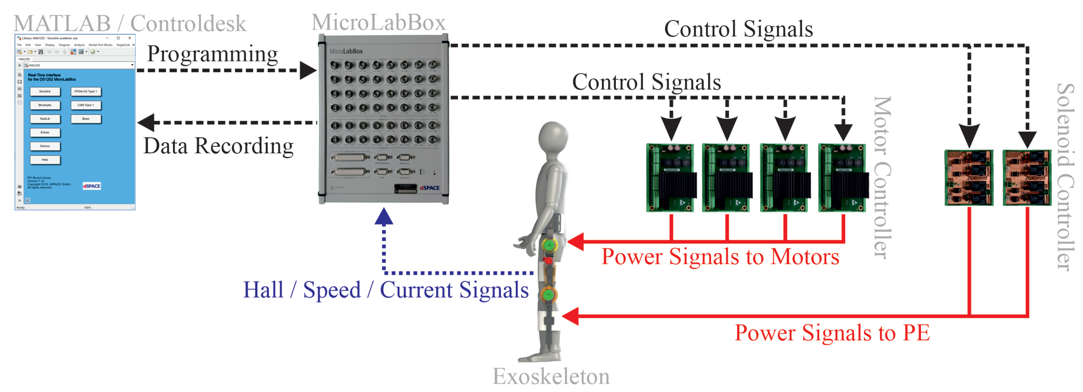
3.1. Experimental Setup

In order to operate and control the L 2 EXP-PE, four Escon 50/8 motor controllers (Maxon Motor AG, Sachseln, Switzerland) are used for the motor modules for the knee and hip. Additionally, two solenoid modules with self-made relay control units are implemented for activating and deactivating the parallel elasticity. A real-time computer (MicroLabBox (MLB), dSPACE GmbH, Paderborn, Germany) is used to control all subordinate control units and record measurement data. The control topology during the experiments is summarized in Figure 5.
Four parallel connected SDR-480P-48 power supplies (MEAN WELL Enterprises, New Taipei, Taiwan) are used to supply the actuators. This configuration provides a nominal voltage and current of 48 V and 36 A, respectively. Regarding the safety of the test subject during the experiments, the power supply units are connected to the power grid via a PSR relay module (Phoenix Contact GmbH & Co. KG, Blomberg, Germany) so that there are two emergency stop buttons to disconnect the power supply. In addition to disconnection from the mains, operating the switch also disables all motor control units. Since it is not possible to recycle the power grid voltage by the DC power supply units used, two DSR 70/30 brake choppers (Maxon Motor AG, Sachseln, Switzerland) were utilized to protect the power supply units. This effectively prevents an overvoltage at the power supply units, only leading to a deactivation of the power supply in the worst case.
The current, speed and Hall sensor signals are measured in the L 2 EXO-PE. The actuator train is not compliant, since both the CPEA and RA motors are connected to the load solely via a harmonic drive transmission. Therefore, the load position can be derived directly from the motor position via the gear reduction. The motors have P = 11 pole pairs and three phases p h = 3, resulting in 33 positive and negative edges in the Hall sensor’s signal during one motor turn. Taking into account the gear ratio of n H D = 50:1, an accuracy of the load position of
Δ φ = π n H D · P · p h 0.002 rad
can be achieved. Additionally, the Hall signals are used to determine the speed in the real-time system. The speed at the load is defined by the time between two edges t s w and the angular displacement
ω = Δ φ t s w .
It follows from the discretization of the angular resolution that the speed changes only when an edge is detected. This behavior can also be observed at the output of the motor controller. If the time between two edges is longer than the previous t s w , l a s t when braking the motor, the running time until the next edge can be used to estimate the speed. Therefore, the current waiting time t s w for the next edge is applied in Equation (2). At a motor speed of 5 rad/s, for example, 0.02 s elapse between two edges. This procedure was used to enable a smooth operation of the actuator even without the use of an additional high-resolution position sensor.

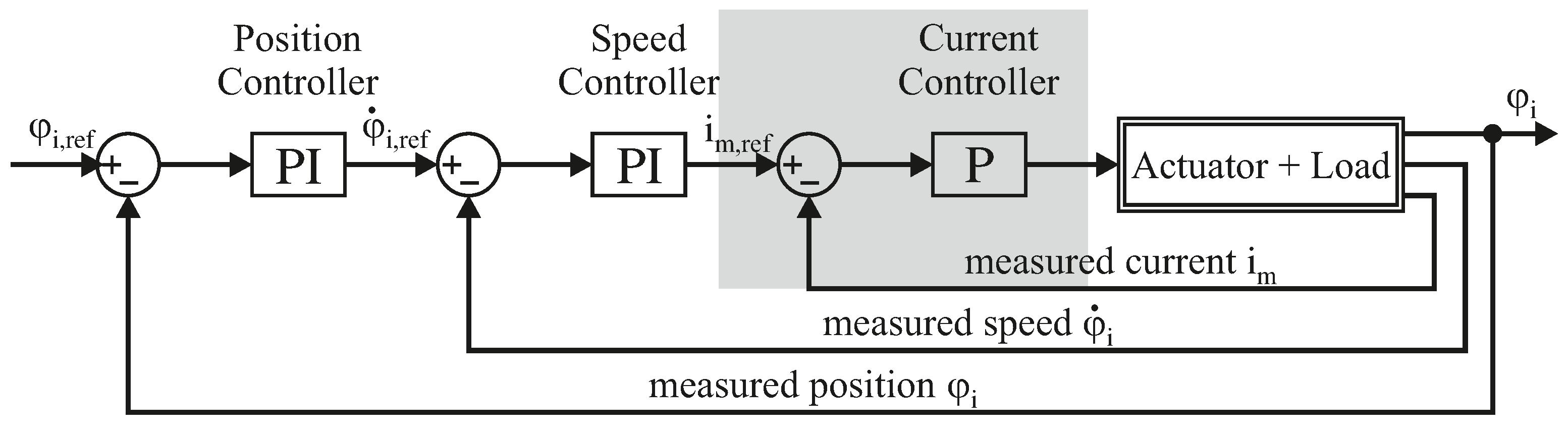
3.2. Actuator Control

A position control system was selected since the target use of this exoskeleton is to support paraplegic patients. A cascaded control is used for this, as shown in Figure 6. The innermost current controller runs on the motor controller with a sampling rate of 53.6 kHz. This electromechanical subsystem of the motor has a time constant of about 1.3 msec; since the other delay sources, such as the PWM with power electronics, react faster, the system can be approximated as a first-order system. The current controller was adjusted using the Escon Studio software (Maxon Motor AG, Sachseln, Switzerland).
For speed and position control, the subject must also be considered as a mechanical load. The exoskeleton and human leg have a joint moment of inertia of about 5.2 kg·m 2 in the swing phase. Where the subject was assumed to be 1.8 m in height and 100 kg in weight. The mass distribution within the leg was assumed according to [23]. For the friction in the entire system, we know the coefficients of friction for the gearbox. According to the data on the gearbox in rated operation, a linearized coefficient of viscous friction of 1.6 Nm·s/rad was assumed. The non-linearity due to the lifting of the masses was neglected in the controller design. The speed and position controllers were designed sequentially based on the model for optimum amplitude. The exoskeleton without human interaction was operated with small step-shaped position references, and the controllers were manually tuned to minimize overshoot. For speed control, the control parameters K P , s = 16 A·s/rad and K I , s = 50 A/rad were selected, for position control K P , p = 20 A·s/rad and K I , p = 4 A/rad. Both superposed controllers are implemented in the real-time system with a sampling rate of 10 kHz.
In the real system there are several restrictions of the system operation. The current must not exceed 8 A, the speed should not exceed 4.4 rad/s and, most importantly, in contact with the subject, no unphysiological joint positions should be achievable (see Section 2.1). The speed and position limits were implemented as saturations in the control system. A limitation of the maximum motor current to 8 A is implemented in the motor controller, which allows a maximum torque of about 55 Nm. Based on these limitations, a windup effect is to be expected. Therefore, both PI controllers were equipped with a clamping according to the permissible values.
In order to implement an emergency stop function in the control layer as well, all motor controllers are activated via a digital enable signal. Redundantly, the emergency switches of the power supply also interrupt the enable line via a relay.
The clutches (bistable solenoids) of the CPEA are locked or released by current pulses of 0.1 s. It should be noted that in the experiments presented, the clutch was only used between experiments to fix the neutral position of the PE during the gait experiments.

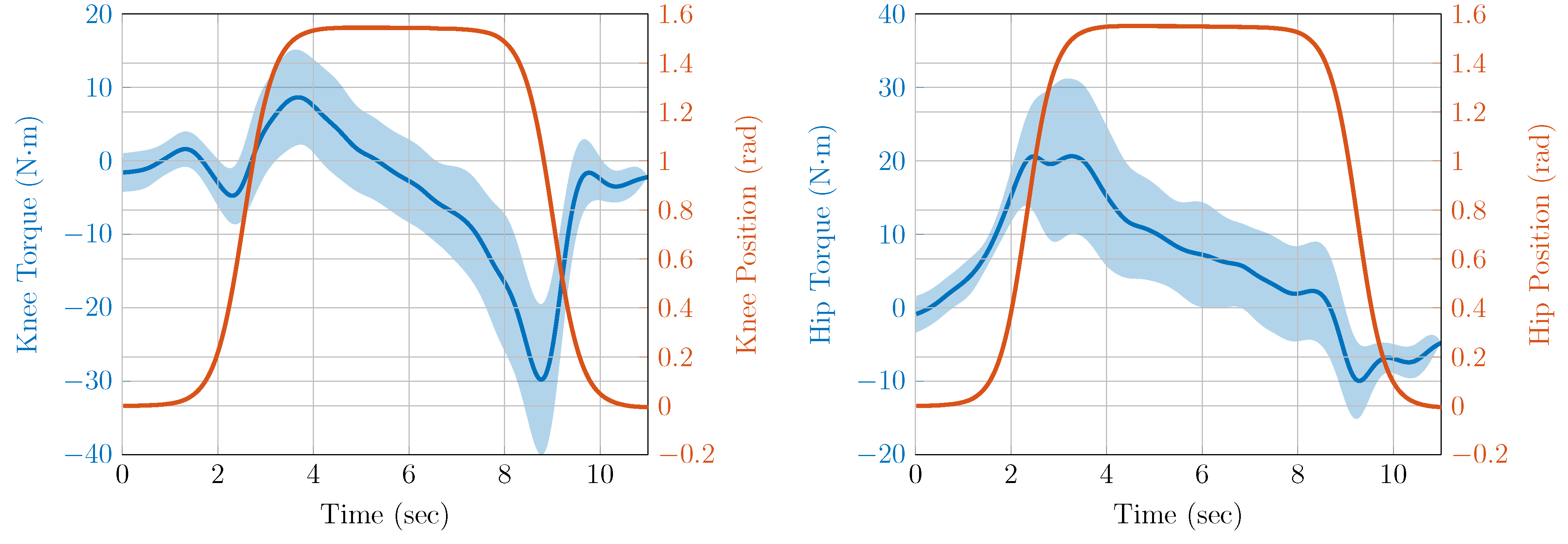
3.3. Simulation of Sit-to-Stand

Before testing the exoskeleton in gait experiments, a simulation of the sit-to-stand and sit-down tasks is provided. The reason is that the actuators (max. 49.4 Nm) cannot fully provide the high torques required during these tasks (max. 90 Nm). Crutches or equivalent assistive devices must be used to achieve this movement task. The simulation indicates the effort a paraplegic patient would have to spend to stand up with the L 2 EXO-PE.
Four healthy male volunteers (age: 31.25 ± 9.3 years, weight 72.9 ± 9.5 kg, body height 1.78 ± 0.08 m) were analyzed in the motion laboratory of Franziskus Hospital, Department of Geriatrics, University Hospital Aachen, to define reference trajectories for the sit-to-stand and sit-down movement tasks. Each of the test subjects had to stand up six times and sit down on a footstool. During the experiments, the subjects were equipped with markers according to a calibrated anatomical system technique (CAST) [24]. The trajectories of the markers were recorded with ten Qualisys OPUS 5+ cameras and the software Qualisys Track Manager 2018 (Qualisys AB, Gothenburg, Sweden) at a frame rate of 120 Hz. The joint angles were determined in Visual3d (C-Motion, Inc., Germantown, MD, USA) with a CAST pipeline from the marker trajectories. The data measured were centered and averaged; see Figure 7. The speed of standing up is comparable to norm values from other literature [21].
In order to approximate the knee ( φ 2 ) and hip ( φ 3 ) trajectories, sigmoid functions
φ 2 ( t ) = p 0 + p 1 1 + e p 2 · ( t p 3 ) ,
φ 3 ( t ) = p 4 p 5 1 + e p 6 · ( t p 7 ) + p 8 1 + e p 9 · ( t p 10 ) ,
where p 0 to p 10 are to be parameterized by the fitting, were used. Regarding the hip and knee trajectories, the root mean square error (RMSE) is 0.004 rad and 0.013 rad for the motion process, respectively. Due to the closeness to the reference, the approximations are not added to Figure 7.
Since the ankle joint of the proposed L 2 EXP-PE prototype is not actuated, no reference trajectory was generated for it. Instead, a trajectory for the simulation of standing up and sitting down was determined for the ankle joint so that the zero moment point can be set at a specific point in the support polygon of the feet. It is assumed that the knee and hip joints move synchronously during this movement task. Thus, the kinetic model is defined, as shown in Figure 8.
A mechanical model is required to estimate the torques of all joints. Since the ankle joint is not actuated, a suitable feed forward control of the joint angle must be used, which corresponds to the ankle joint work done by therapists or healthy volunteers. The static center of gravity point must stay within the foot support area to balance the exoskeleton and volunteer during the sit-to-stand task [25]. A function needs to be found for the model shown in Figure 8 with the controlled knee and hip joints that calculates the center of gravity as a function of φ 2 and φ 3 . The feet are assumed to be in permanent contact with the floor, and the feet and floor are connected with very high friction. Regarding the calculation of the total center of gravity (COG) position, the vector r x
r x = s i n ( φ 1 ) · d 1 s i n ( φ 1 ) · l 1 + s i n ( φ 1 φ 2 ) · d 2 s i n ( φ 1 ) · l 1 + s i n ( φ 1 φ 2 ) · l 2 + s i n ( φ 1 φ 2 + φ 3 ) · l 3
of individual centers of gravity is calculated, where d i and l i denote the length of the links and the position of the center of mass within each link. The links are reduced in the mass points m i . The position x COG of the center of gravity
x COG = i = 1 3 m i · r x , i m 1 + m 2 + m 3
is the weighted center of all masses. In order to calculate the ankle angle required φ 1 = f ( φ 2 , φ 3 , x COG ) , Equation (5) was rearranged in Maple 2018 (Waterloo Maple Inc., Waterloo, ON, Canada), where the position of the center of gravity desired x COG is maintained. A model was derived to calculate the joint torques according to the Lagrange formalism from the abstracted mechanical system shown in Figure 8. We note that the potential energy of the three point masses m i is given by
E p o t = d 1 · c o s ( φ 1 ) · g · m 1 ( l 1 · c o s ( φ 1 ) + d 2 · c o s ( φ 1 φ 2 ) ) · g · m 2 ( l 1 · c o s ( φ 1 ) + l 2 · c o s ( φ 1 φ 2 ) + d 3 · c o s ( φ 1 φ 2 + φ 3 ) ) · g · m 3 ,
where the angles φ i represent the generalized coordinates. The kinetic energy of the three point masses m i is defined by
E k i n , 1 = φ ˙ 1 2 d 1 2 m 1 2 E k i n , 2 = ( l 1 φ ˙ 1 c o s ( φ 1 ) + d 2 ( φ ˙ 1 φ ˙ 2 ) c o s ( φ 1 φ 2 ) ) 2 + ( l 1 φ ˙ 1 s i n ( φ 1 ) + d 2 ( φ ˙ 1 φ ˙ 2 ) s i n ( φ 1 φ 2 ) ) 2 m 2 2 E k i n , 3 = ( ( l 1 φ ˙ 1 c o s ( φ 1 ) + l 2 ( φ ˙ 1 φ ˙ 2 ) c o s ( φ 1 φ 2 ) + d 3 ( φ ˙ 1 φ ˙ 2 + φ ˙ 3 ) c o s ( φ 1 φ 2 + φ 3 ) ) 2 + ( l 1 φ ˙ 1 s i n ( φ 1 ) + l 2 ( φ ˙ 1 φ ˙ 2 ) s i n ( φ 1 φ 2 ) + d 3 ( φ ˙ 1 φ ˙ 2 + φ ˙ 3 ) s i n ( φ 1 φ 2 + φ 3 ) ) 2 ) m 3 2 .
The Lagrangian function is defined as the sum of all vector entries L = i = 1 3 ( E K i n , i E P o t , i ) from Equations (6) and (7).
The equations of motion for the three degrees of freedom are determined by derivation of the Lagrange function d d t δ L δ φ ˙ i δ L δ φ i = Q i , where Q i are external generalized torques. The equations of motion of the system are provided in Appendix A.1.
In order to simulate the effect of crutches during exoskeleton support, a vertical crutch force is added at the shoulder above mass m 3 , which is represented by F c in Figure 8. The torque acting on the individual joints as a result of a crutch force is defined by
τ c = ( s i n ( φ 1 φ 2 + φ 3 ) · l 4 + s i n ( φ 1 φ 2 ) · l 2 + s i n ( φ 1 ) · l 1 ) · F c ( s i n ( φ 1 φ 2 + φ 3 ) · l 4 + s i n ( φ 1 φ 2 ) · l 2 ) · F c s i n ( φ 1 φ 2 + φ 3 ) · l 4 · F c ,
where a positive torque points in a positive coordinate direction; see Figure 8. Complete support of the sit-to-stand is not possible with the actuator presented in this study without significant joint torque overload. The simulation is intended to determine the crutch force that would be required to enable the user to stand up with the exoskeleton realized. Research on this exoskeleton is intended to provide long-term advantages for the support of paraplegics, although it can also be assumed that this target group has sufficiently healthy upper body muscles. Since the sitting phases are not modeled in the simulation, the movement is reduced to a bend of the knees in which the upper body does not straighten up after taking a seat. This simplified motion with the second term removed in Equation (4) will also be used later for the sit-to-stand experiments. Torque trajectories with and without crutch force F c can be compared with the trajectories defined by Equations (3) and (4) and a weight partition according to [23] (see Figure 9). The joint torques for knee and hip can be significantly reduced by an additional crutch force.
The crutch force F c in the simulation is a maximum of 30% of the subject’s weight. The knee torque is higher during sit-to-stand, and the reduction due to the crutch forces is also lower. The maximum knee torque of τ 2 = 1.25 Nm/kg is reduced to τ 2 = 0.60 Nm/kg by a crutch force associated with approximately 30 % of the body weight. This crutch force also reduces the maximum torque load on the hip actuator from 1.7 to 0.35 Nm/kg. Assuming the nominal torque of 49.4 Nm from Table 2, this would make it possible to support people weighing up to about 82 kg.

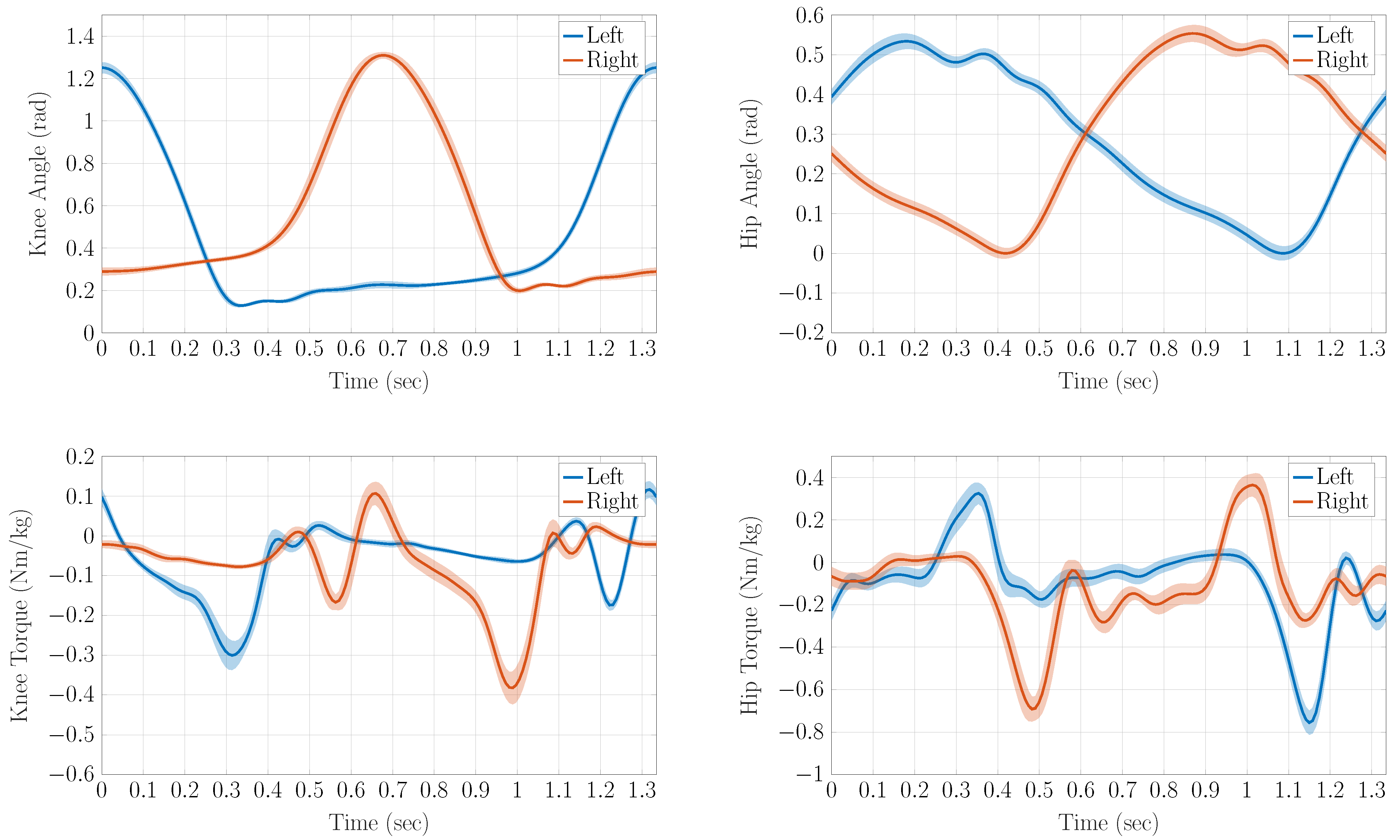
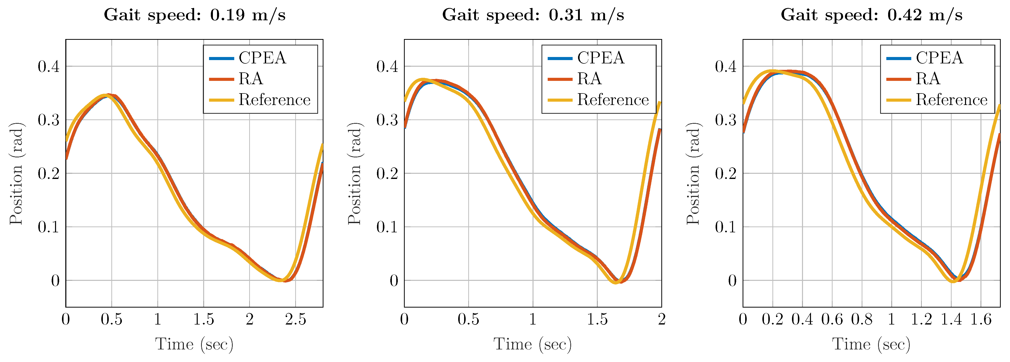
3.4. Gait Experiments

The gait of a healthy volunteer was recorded to define gait trajectories for the experiments. The volunteer was labeled with reflective markers according to the CAST scheme. For motion recording, Qualisys OPUS 5+ cameras (Qualisys AB, Gotheburg, Sweden) with the framerate 120 Hz were used. Two minutes of constant and normalized gait velocity were recorded on a treadmill. The joint angles and torques were determined in Visual3d (C-Motion, Inc., Germantown, MD, USA). All individual steps of the course sequence were averaged, and the standard deviation was determined. The standard deviation of the position reference is smaller than 0.023 rad, as shown in the first row of Figure 10. This shows the periodicity of the gait pattern. The joint torques, which are given in the second row of Figure 10, help to determine an optimal constant of the parallel spring [14,15].
In order to obtain a continuous and smooth reference of the joint angles, the Fourier sequence is determined to reconstruct the gait data
φ i , F o u r i e r ( t ) = c 0 + k = 1 c k · c o s ( ω · k · ( t + c p k ) ) ,
where ω is the base frequency, which is calculated as the inverse of the average gait cycle time T G C . The variables c p k represent a phase offset of the individual frequencies, c 0 a constant component and c k the magnitudes at the individual frequencies. The RMSE
e R M S = 1 T G C t = 0 T G C ( φ i , F o u r i e r ( t ) φ i ( t ) ) 2 d t ,
was used to estimate the quality of the fitting. The parameters determined are summarized in Table 3. The knee trajectory of a gait velocity of 0.19 m/s proved to be the most erroneous in the approximation. The RMSE is 0.011 rad with a fifth-order Fourier sequence; with the fourth-order approximation, the RMSE (0.022 rad) is still almost double. For the hip trajectory, the RMSE for a fifth-order approximation is about 0.005 rad for all three velocities. Reducing the order by one and two increases the RMSE of the approximated hip trajectory to 0.007 and 0.012 rad, respectively. The right and left joints are each shifted by half a gait cycle for the reference trajectories.

3.5. Ethics Committee (EK190-19)

The experimental protocol was reviewed by RWTH Aachen University Hospital’s ethics committee (EK190-19), and no concerns were raised.

4. Results

Results with active motion support for sit-to-stand and gait experiments are provided below.

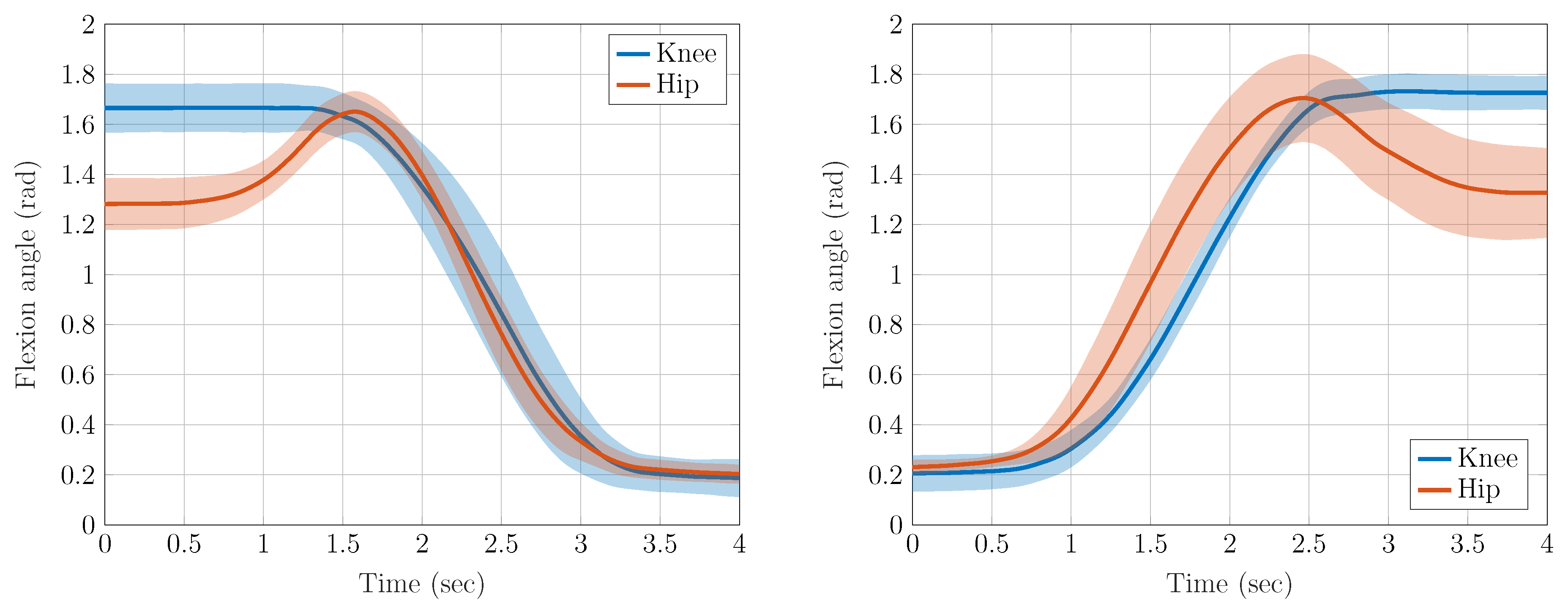
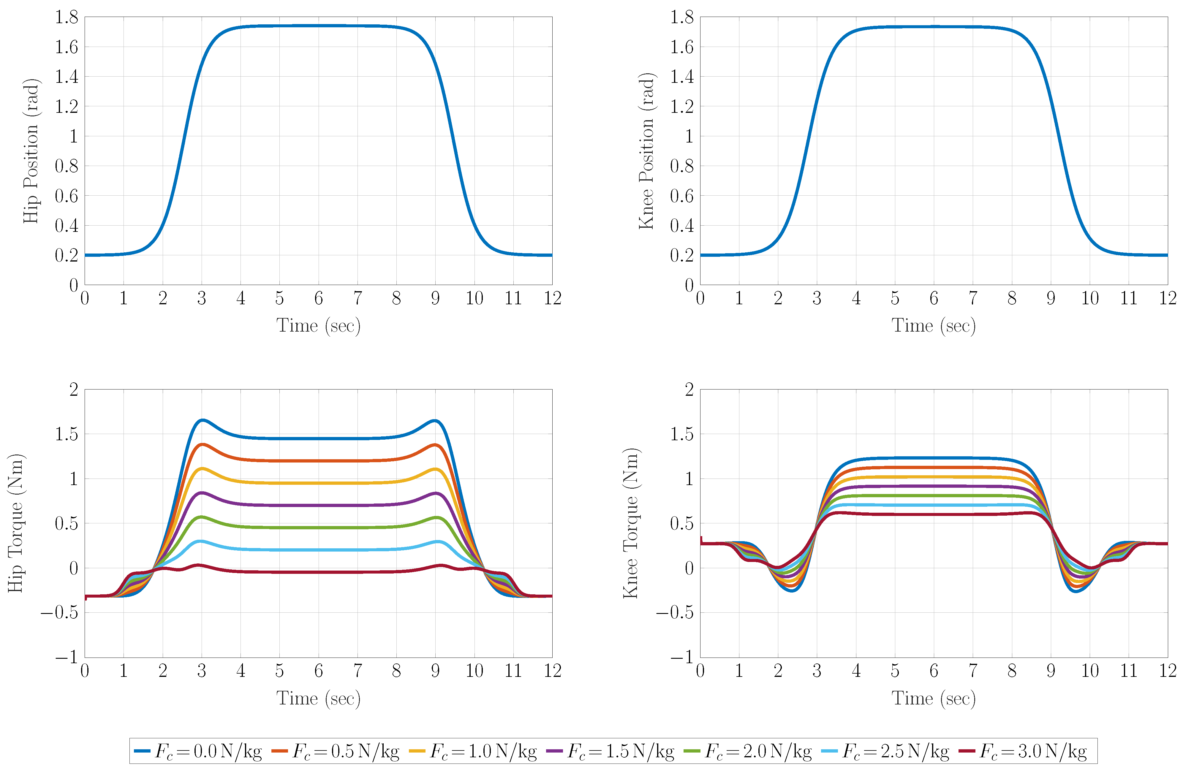
4.1. Results of Sit-to-Stand Experiments

Regarding the experiments, the exoskeleton supported a healthy volunteer (height: 1.8 m, age: 33 years, weight: 78 kg) in standing up and sitting down; see Figure 11. To determine the additional force that a test person must apply, a rope attached to the ceiling was equipped with a PSD-S1 force sensor (Pushton electronic instruments Co., Zhengzhou, China); See Figure 12. The subject held on to the rope during the tests, and the rope force data were recorded. The subject performed the experiment a total of 22 times, and the data were averaged over all experiments as the shape of the torque trajectories was always the same. The maximal rope force average was about 350 N, which corresponds to approximately 43% of the weight of the test subject. When supporting the volunteer, the maximum joint torque average of the exoskeleton was approximately 23 Nm and 33 Nm for hip and knee, respectively.
In the phase between lowering and lifting, the modeling deviates from the experimental results. A lower torque was required in the experiments, since the test person automatically tilted slightly forward during the tests. In view of both results, however, it can be concluded that the exoskeleton can provide support in sit-to-stand tasks.
As documented in Table 2, the actuators can provide a continuous torque of about 50 Nm, from which friction losses are subtracted. The gearbox installed has a maximum allowable torque of 98 Nm [26]. This limits the maximum torque of the actuator. The motor and motor control unit allow a short-term torque overload of the motor to approximately double the torque (100 Nm). The motor current has been limited to 8 A to protect the gearbox, resulting in a load-related maximum motor torque of 55 Nm. Regarding future work, an actuator prototype has already been developed that can provide up to 105 Nm (35 Nm + 70 Nm) through the parallel combination of SEA and direct drive [27]. In the future, this actuator must be optimized and integrated into the exoskeleton to provide full support when raising a paraplegic patient. Nevertheless, the exoskeleton can already support a test subject considerably in the movement task. Even if the seat height is reduced [28] or the speed of movement is increased [21], the actuator torques available are in an appropriate range, so no modification of the design is required for operation with patients.

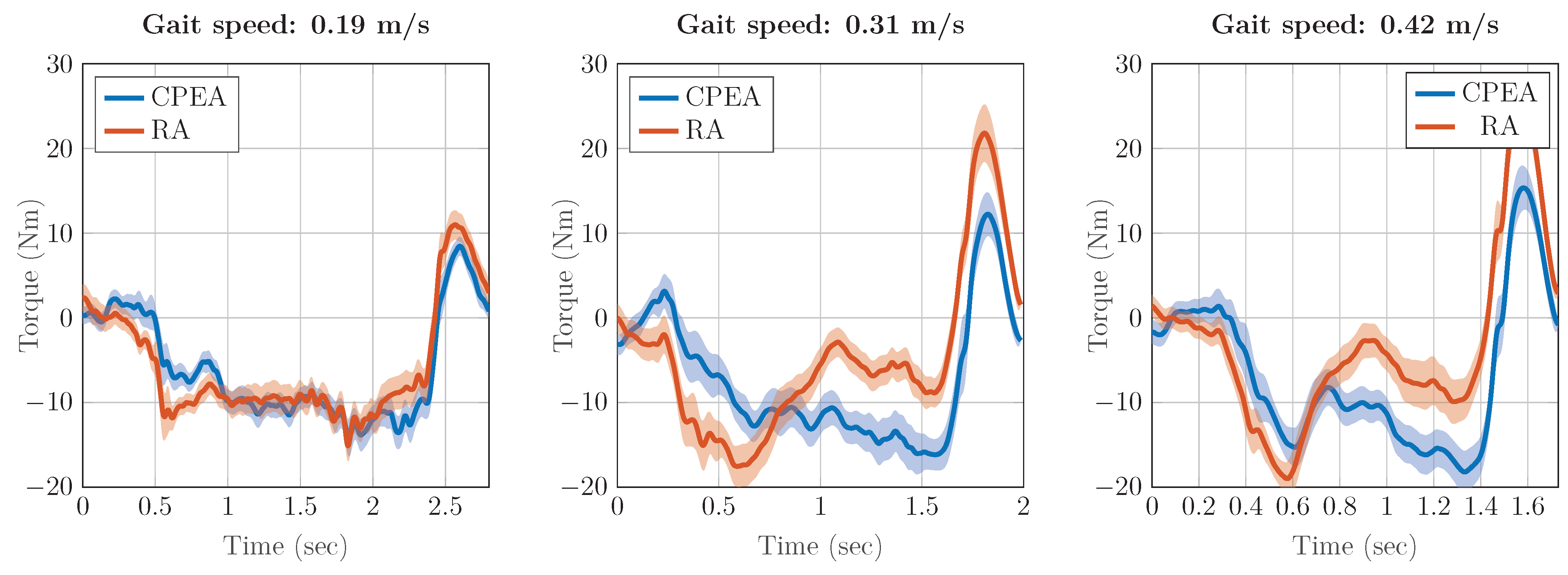
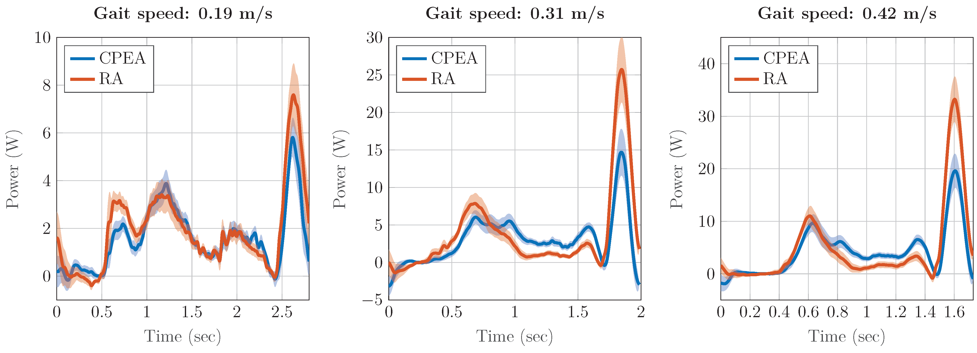
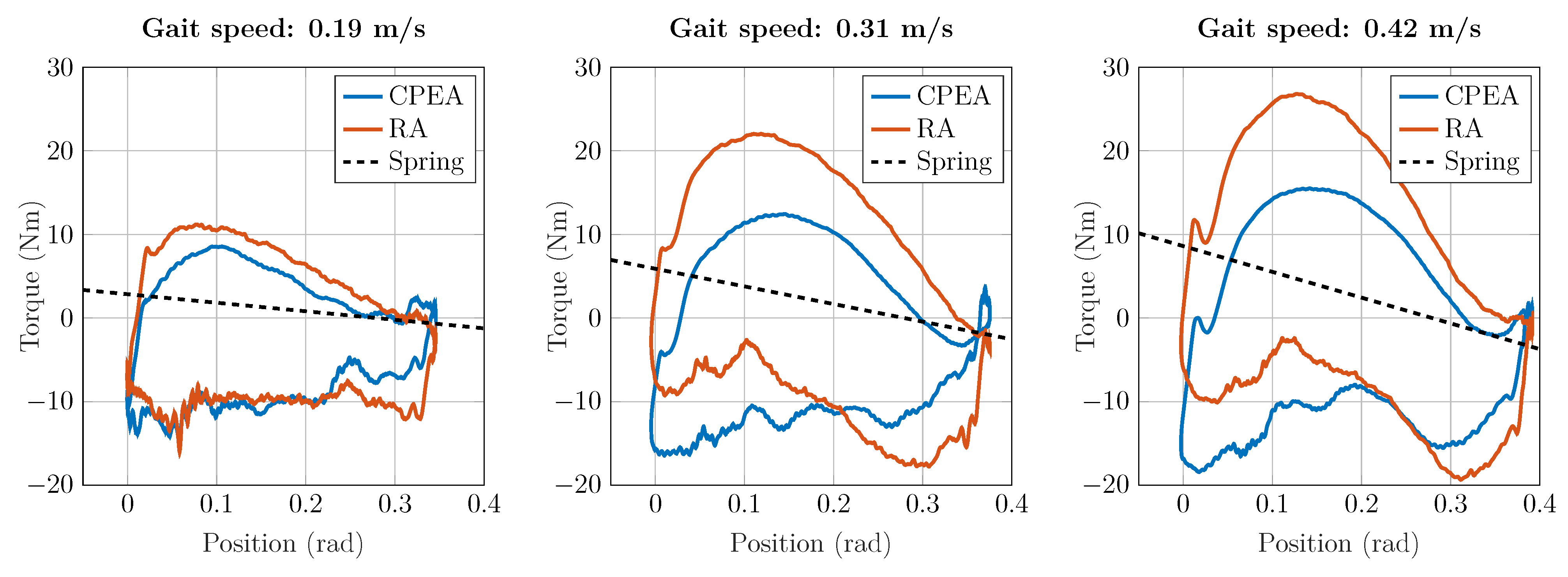
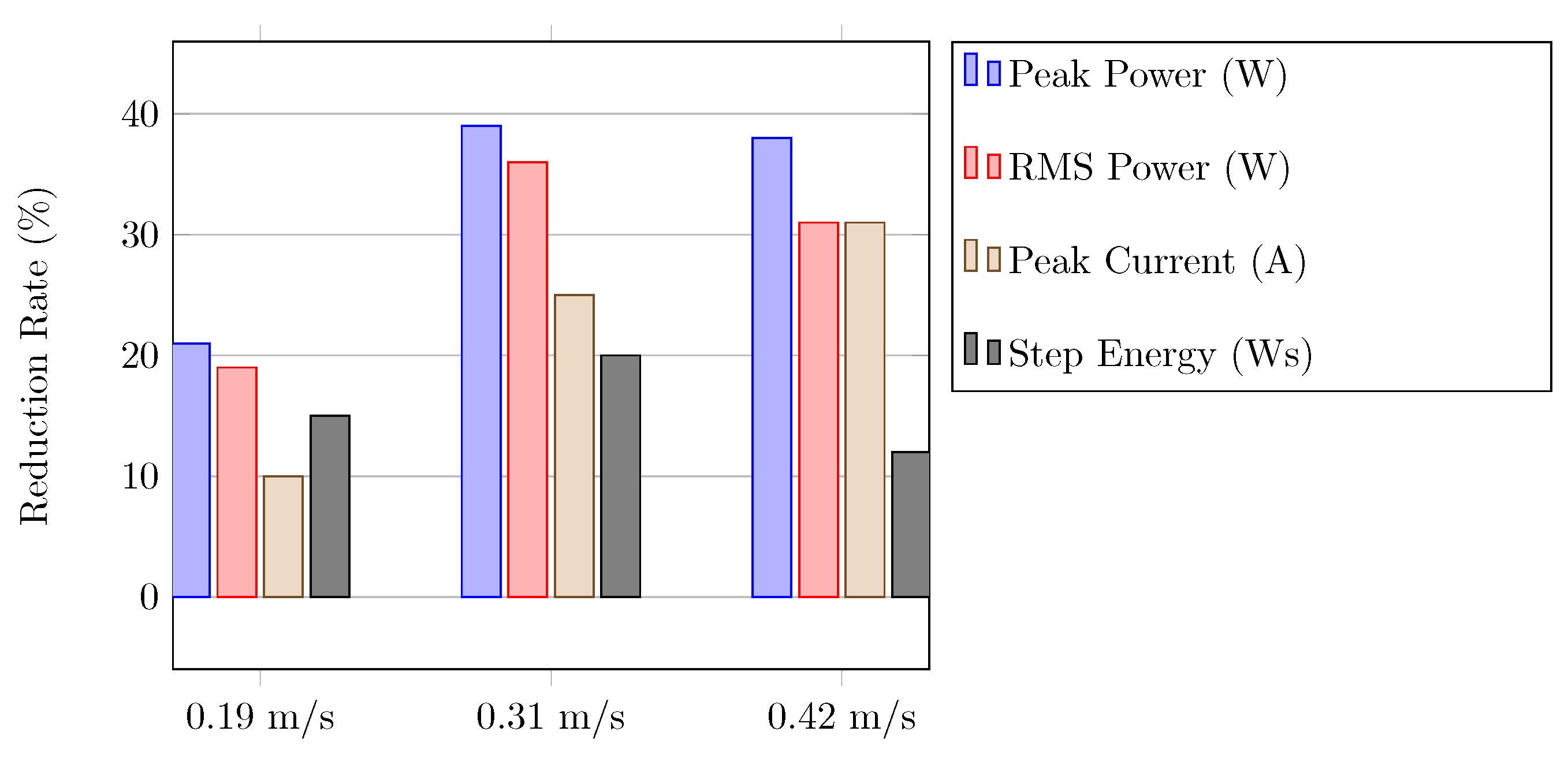
4.2. Results of Gait Experiments

In order to analyze the L 2 EXO-PE performance, the gait of a healthy volunteer (height: 1.8 m, age: 33 years, weight: 78 kg) on a treadmill was recorded at three different settings. The volunteer walked as passively as he could during the trials. One hip actuator was operated as RA, the other as CPEA. Springs with 10.2, 21.1 and 30.8 Nm/rad were used for the realization of the CPEA. Velocities according to Table 3 (0.19, 0.31 and 0.42 m/s) were implemented. At least four minutes were recorded at each of the three settings in each of the gait experiments, so that 89, 123 and 144 complete gait cycles were recorded for the different velocities. All measurement data were averaged over the number of gait cycles.
It was observed during the gait tests that the mean trajectories follow the reference with a time delay of a maximum of 0.05 s. In Figure 13, this effect was more noticeable at faster gait velocities due to shorter cycle times, but the absolute shift was consistent. The standard deviation is not shown due to the small deviation. The deviation of the mean trajectories of CPEA and RA is in the range of the angular resolution. A comparison of the joint torque and power consumption is justified since the two position trajectories of the two actuators overlap.
The graphs in Figure 14 visualize the averaged hip torque of the gait trials. It should be noted that the gait velocities realized are low. Therefore, a relatively low joint torque and power consumption is to be expected, which is also in accordance with the observations of other studies [19,29,30]. In this application, however, a higher velocity would also lead to a relatively higher improvement due to the PE. The maximum torque at the RA was 15.1, 21.8 and 26.5 Nm for the gait velocities 0.19, 0.31 and 0.42 m/s, respectively. These values can be reduced to 13.8, 16.1 and 18.4 Nm, respectively, by using a PE. The results of the joint torque measurements show that the maximum torque can be reduced by the PE by at least 20%.
We recall that the power consumption of the motor can be calculated from the motor current and the motor voltage, which is the sum of the ohmic losses and the induced voltage
P e l e c t r . = i · ( R M o t o r · i + K M o t o r · ω M o t o r ) ,
where R M o t o r = 0.29 Ω is the motor resistance, K M o t o r = 0.136 Vs/rad is the motor constant, ω M o t o r is the motor speed and i is the motor current. When examining the power consumption over the data averaged, it is observed that the maximum torque (see Figure 14) correlates with the maximum power consumption (see Figure 15). This metric is also where the greatest relative reduction can be found due to the PE. The application of the PE reduces the maximum power consumption from 7.6, 25.7 and 33.2 W to 5.8, 14.7 and 16.5 W, respectively. The design of the springs was based on the position and torque characteristics of a spring, which only indirectly aimed at minimizing the maximum power consumption.
In addition to the maximum power consumption, the step energy required is also important. The negative power components in Figure 15 during the experiments are dissipated by the brake choppers. Therefore, the exoskeleton in the current realization is not able to recuperate energy, and only positive values
P H i p + = m a x ( 0 , P H i p )
of the power are considered in the energy calculation. The energy required for one step is calculated as the integral of the power consumption P H i p + during one step
E S t e p = 0 T G C P H i p + d t .
Due to the use of the PE, the step energy decreases from 5.4, 7.8 and 8.3 Ws to 4.5, 6.3 and 7.4 Ws, respectively. This can reduce the power consumption of one actuator for an hour of operation from 1.91 to 1.61 Wh, from 3.90 to 3.18 Wh and from 4.79 to 4.25 Wh for the gait velocities 0.19, 0.31 and 0.42 m/s, respectively.
The configuration of the balance point of the PE was shown in [14,15]. Figure 16 provides the angle and torque characteristics experimentally determined for the three gait velocities, including the spring configurations realized for each case. It is important to note that different spring elements are required to realize different spring stiffnesses. Implementing new spring constants would, therefore, require a reconfiguration of the actuator. Theoretically optimal PE can, therefore, hardly be implemented practically in the prototype. However, the intended effect of the PE can already be verified in the experiments, as the characteristics in Figure 16 clearly show.
Finally, the various advantages in the gait experiments are summarized. For this purpose, the different reduction rates due to the PE for peak power, RMS power, peak current (electric torque) and step energy are presented in the bar chart Figure 17. The lowest improvements are achieved for the lowest gait velocity. With increasing gait velocity, the maximum torque (Figure 14) also increases, which leads to higher improvements.

5. Conclusions

This study demonstrated that partial support for sit-to-stand can be provided by our exoskeleton prototype. Assuming that the patient needs to use crutches for gait stability, these can provide an additional force for standing up. However, additional experiments with impaired individuals are required to verify whether this torque deficiency leads to a deficit in movement tasks. Alternatively, a mechanical design already exists for increasing the torque of the actuator during sit-to-stand [27].
The gait experiments have shown that the power design of the actuators is appropriate, since a maximum torque of about 30 Nm was recorded and the speed range is defined as required by the motion task. This finding is also in line with the results of other studies [3,5]. The experimental validation of the increase in efficiency of the upright gait of an exoskeleton through the use of a PE is a new finding. The optimal efficiency advantages determined simulatively by Wang et al. could not be reached, but they are predicted at gait speeds at least twice as fast, which severely limits comparability [14]. In particular, the reduction of the peak torque by up to 31% is a major advantage that directly affects the mass of the actuator required in the electromechanical design. The reduction of the RMS power by up to 36% allows for a longer lifetime or a smaller design of the battery pack in future autonomous gait experiments. These could be important steps in the realization of a clinical prototype.
The hip actuator is designed to meet the performance requirements of the motion tasks such as RA and CPEA. The prototype design with its actuators achieves a similar power to mass ratio as the exoskeletons in Table 1. Based on the study conducted and the requirement changes that arise, a lightweight version of the hip actuator can be designed.
These experimental results make the exoskeleton prototype promising for clinical application. Clinical studies with paraplegic patients are needed to investigate how the efficiency of powered gait can be increased by the PE and whether all motion tasks can be realized by means of the exoskeleton.

Author Contributions

Conceptualization, B.P.; data curation, B.P.; formal analysis, B.P.; funding acquisition, B.P., L.J. and S.L.; investigation, B.P.; methodology, B.P.; project administration, B.P. and C.N.; resources, B.P.; software, B.P.; supervision, L.J. and S.L.; validation, B.P., L.B.; visualization, B.P.; writing, original draft, B.P.; writing, review and editing, B.P., L.B., Y.L., C.N., L.J., S.L. All authors have read and agreed to the published version of the manuscript.

Funding

The research was funded by the joint DFG-NSFC project “Hybrid parallel compliant actuation for lower limb rehabilitation-HYPACAL” (LE 817/34-1) (NSFC 51761135121).

Institutional Review Board Statement

The experimental protocol was reviewed by RWTH Aachen University Hospital’s ethics committee (EK190-19), and no concerns were raised.

Informed Consent Statement

Informed consent was obtained from all subjects involved in the study.

Acknowledgments

The authors want to thank Raphael Bonarens (RWTH Aachen University), Mustafa Enes Fincan (RWTH Aachen University) and David Weddeling (FH Aachen University of Applied Sciences) for technical assistance and fruitful discussions. The authors want to thank Harald Jorias (Fednel und Keuchen/Das Sanitätshaus, Aachen, Germany) and Dietmar Faßbänder (Scientific workshop of The Institute of Applied Medical Engineering, RWTH Aachen University) for their help and support in realizing the prototype. The authors would like to thank Carl-Friedrich Benner (RWTH Aachen University) for their vigorous support in collecting the measurement data.

Conflicts of Interest

The authors declare no conflict of interest. The funders had no role in the design of the study, in the collection, analyses or interpretation of data, in the writing of the manuscript, or in the decision to publish the results.

Abbreviations

The following abbreviations are used in this manuscript:
BLDCBrushless Direct Current
CPEAClutched Parallel Elastic Actuator
MLBMicroLabBox
PEParallel Elasticity
PEAParallel Elastic Actuator
RARigid Actuator
RMSRoot Mean Square
SEASerial Elastic Actuator

Appendix A. Lagrange

The source code is from a Matlab Function. The joint angles φ i are combined in the vector Q. The derivatives φ ˙ i and φ ¨ i are combined into the vectors Qdot and Qdotdot. The model expects masses m i in kg, lengths l i and d i in m, all angles Q are in rad and the gravitational acceleration g is assumed to be 9.81 m/s.

Appendix A.1. Joint Torques

% Calculation of gravitational Torques
G(1) = g*d1*sin(Q(1))*m1+sin(Q(1))*g*l1*m2+sin(-Q(2)+Q(1))*g*d2*m2 ...
+ sin(Q(1))*g*l1*m3+sin(Q(1)-Q(2))*g*l2*m3 + sin(Q(3)+Q(1)-Q(2))*g*d3*m3;
G(2) = -sin(Q(1)-Q(2))*g*d2*m2 - sin(Q(1)-Q(2))*g*l2*m3 ...
- sin(Q(3)+Q(1)-Q(2))*g*d3*m3;
G(3) = sin(Q(3)+Q(1)-Q(2))*g*d3*m3;
GM = G;
% Calculation of Coriolis Matrix
C(1,1)= 2*Qdot(2)*d3*l1*m3*sin(Q(2)-Q(3)) + 2*Qdot(2)*l1*l2*m3*sin(Q(2)) ...
+ 2*Qdot(3)*d3*l2*m3*sin(Q(3)) - 2*Qdot(3)*d3*l1*m3*sin(Q(2)-Q(3)) ...
+ 2*Qdot(3)*d3*l2*m3*sin(Q(3)) + 2*Qdot(2)*d2*l1*m2*sin(Q(2));
C(1,2)= -Qdot(2)*d2*l1*m2*sin(Q(2)) - Qdot(2)*l1*l2*m3*sin(Q(2)) ...
- Qdot(2)*d3*l1*m3*sin(Q(2)-Q(3)) + 2*Qdot(3)*d3*l1*m3*sin(Q(2)-Q(3)) ...
- 2*Qdot(3)*d3*l2*m3*sin(Q(3));
C(1,3)= -Qdot(3)*d3*l1*m3*sin(Q(2)-Q(3)) + Qdot(3)*d3*l2*m3*sin(Q(3));
C(2,1) = -Qdot(1)*d2*l1*m2*sin(Q(2)) - Qdot(1)*l1*l2*m3*sin(Q(2)) ...
- Qdot(1)*d3*l1*m3*sin(Q(2)-Q(3)) - 2*Qdot(3)*d3*l2*m3*sin(Q(3));
C(2,2) = 2*Qdot(3)*d3*l2*m3*sin(Q(3));
C(2,3) = -Qdot(3)*d3*l2*m3*sin(Q(3));
C(3,1) = Qdot(1)*d3*l1*m3*sin(Q(2)-Q(3)) - Qdot(1)*sin(Q(3))*d3*l2*m3 ...
+ 2*Qdot(2)*sin(Q(3))*d3*l2*m3;
C(3,2) = -Qdot(2)*sin(Q(3))*d3*l2*m3;
% Calculation of Coriolis torques
CM=C*Qdot;
% Calculation of Mass Matrix
M(1,1) = -d1 2 *m1 - d2 2 *m2 - d3 2 *m3 - l1 2 *m2 - l1 2 *m3 - l2 2 *m3 ...
- 2*d3*l2*m3*cos(Q(3)) - 2*d2*l1*m2*cos(Q(2)) - 2*l1*l2*m3*cos(Q(2)) ...
- 2*d3*l1*m3*cos(Q(2)-Q(3));
M(1,2) = d2 2 *m2 + d3 2 *m3 + l2 2 *m3 + 2*d3*l2*m3*cos(Q(3)) ...
+ d2*l1*m2*cos(Q(2)) + l1*l2*m3*cos(Q(2)) + d2*l1*m2*cos(Q(2)) ...
+ l1*l2*m3*cos(Q(2)) + d3*l1*m3*cos(Q(2)-Q(3));
M(1,3) = -d3*l2*m3*cos(Q(3)) - d3*l1*m3*cos(Q(2)-Q(3)) - d3 2 *m3;
M(2,1) = d2 2 *m2 + d3 2 *m3 + l2 2 *m3 + 2*d3*l2*m3*cos(Q(3)) ...
+ d2*l1*m2*cos(Q(2)) + l1*l2*m3*cos(Q(2)) + d3*l1*m3*cos(Q(2)-Q(3));
M(2,2) = -d2 2 *m2 - d3 2 *m3 - l2 2 *m3 - 2*d3*l2*m3*cos(Q(3));
M(2,3) = d3*l2*m3*cos(Q(3)) + d3 2 *m3;
M(3,1) = -d3*l1*m3*cos(Q(2)-Q(3)) - d3*l2*m3*cos(Q(3)) -d3 2 *m3;
M(3,2) = d3 2 *m3 + d3*l2*m3*cos(Q(3));
M(3,3) = -d3 2 *m3;
% Calculation of inertial Torques
MM = M*Qdotdot;
% Jointtorques
Ankletorque = GM(1) + CM(1) + MM(1);
Kneetorque = GM(2) + CM(2) + MM(2);
Hiptorque = GM(3) + CM(3) + MM(3);

References

  1. Schütz, A. Robotic Exoskeleton: For a Better Quality of Life. Maxon Motor 2012. Available online: https://www.maxongroup.com/maxon/view/application/Robotic-exoskeleton-For-a-better-quality-of-life (accessed on 28 March 2021).
  2. Gorgey, A.S.; Sumrell, R.; Goetz, L.L. Exoskeletal assisted rehabilitation after spinal cord injury. In Atlas of Orthoses and Assistive Devices; Elsevier: Amsterdam, The Netherlands, 2019; pp. 440–447. [Google Scholar]
  3. Colombo, G.; Joerg, M.; Schreier, R.; Dietz, V. Treadmill training of paraplegic patients using a robotic orthosis. J. Rehabil. Res. Dev. 2000, 37, 693–700. [Google Scholar] [PubMed]
  4. Tabti, N.; Kardofaki, M.; Alfayad, S.; Chitour, Y.; Ouezdou, F.B.; Dychus, E. A Brief Review of the Electronics, Control System Architecture, and Human Interface for Commercial Lower Limb Medical Exoskeletons Stabilized by Aid of Crutches. In Proceedings of the 2019 28th IEEE International Conference on Robot and Human Interactive Communication (RO-MAN), New Delhi, India, 14–18 October 2019; pp. 1–6. [Google Scholar]
  5. Zhang, T.; Tran, M.; Huang, H. Design and experimental verification of hip exoskeleton with balance capacities for walking assistance. IEEE/ASME Trans. Mechatron. 2018, 23, 274–285. [Google Scholar] [CrossRef]
  6. Neuhaus, P.D.; Noorden, J.H.; Craig, T.J.; Torres, T.; Kirschbaum, J.; Pratt, J.E. Design and Evaluation of Mina: A Robotic Orthosis for Paraplegics. In Proceedings of the IEEE International Conference on Rehabilitation Robotics, Zurich, Switzerland, 29 June–1 July 2011; pp. 1–8. [Google Scholar]
  7. Wang, S.; Wang, L.; Meijneke, C.; Van Asseldonk, E.; Hoellinger, T.; Cheron, G.; Ivanenko, Y.; La Scaleia, V.; Sylos-Labini, F.; Molinari, M.; et al. Design and control of the MINDWALKER exoskeleton. IEEE Trans. Neural Syst. Rehabil. Eng. 2014, 23, 277–286. [Google Scholar] [CrossRef] [PubMed]
  8. Mummolo, C.; Peng, W.Z.; Agarwal, S.; Griffin, R.; Neuhaus, P.D.; Kim, J.H. Stability of mina v2 for robot-assisted balance and locomotion. Front. Neurorobotics 2018, 12, 62. [Google Scholar] [CrossRef]
  9. Liu, L.; Hong, Z.; Penzlin, B.; Misgeld, B.; Ngo, C.; Bergmann, L.; Leonhardt, S. Low impedance-guaranteed gain-scheduled GESO for torque-controlled VSA, with application of exoskeleton-assisted sit-to-stand. IEEE/ASME Trans. Mechatron. 2020. [Google Scholar] [CrossRef]
  10. Masood, J.; Ortiz, J.; Fernández, J.; Mateos, L.A.; Caldwell, D.G. Mechanical Design and Analysis of Light Weight Hip Joint Parallel Elastic Actuator for Industrial Exoskeleton. In Proceedings of the 2016 6th IEEE International Conference on Biomedical Robotics and Biomechatronics (BioRob), Singapore, 26–29 June 2016; pp. 631–636. [Google Scholar] [CrossRef]
  11. Verstraten, T.; Beckerle, P.; Furnémont, R.; Mathijssen, G.; Vanderborght, B.; Lefeber, D. Series and parallel elastic actuation: Impact of natural dynamics on power and energy consumption. Mech. Mach. Theory 2016, 102, 232–246. [Google Scholar] [CrossRef]
  12. Plooij, M.; Wisse, M.; Vallery, H. Reducing the energy consumption of robots using the bidirectional clutched parallel elastic actuator. IEEE Trans. Robot. 2016, 32, 1512–1523. [Google Scholar] [CrossRef] [Green Version]
  13. Aftabi, H.; Nasiri, R.; Ahmadabadi, M.N. A kinematic index for estimation of metabolic rate reduction in running with I-RUN. bioRxiv 2020. [Google Scholar] [CrossRef]
  14. Wang, S.; Van Dijk, W.; van der Kooij, H. Spring Uses in Exoskeleton Actuation Design. In Proceedings of the IEEE International Conference on Rehabilitation Robotics (ICORR), Zurich, Switzerland, 29 June–1 July 2011. [Google Scholar]
  15. Penzlin, B.; Enes Fincan, M.; Li, Y.; Ji, L.; Leonhardt, S.; Ngo, C. Design and Analysis of a Clutched Parallel Elastic Actuator. Actuators 2019, 8, 67. [Google Scholar] [CrossRef] [Green Version]
  16. Li, Y.; Guan, X.; Li, Z.; Tang, Z.; Penzlin, B.; Yang, Z.; Leonhardt, S.; Ji, L. Analysis, design, and preliminary evaluation of a parallel elastic actuator for power-efficient walking assistance. IEEE Access 2020, 8, 88060–88075. [Google Scholar] [CrossRef]
  17. Li, Y.; Li, Z.; Penzlin, B.; Tang, Z.; Liu, Y.; Guan, X.; Ji, L.; Leonhardt, S. Design of the Clutched Variable Parallel Elastic Actuator (CVPEA) for Lower Limb Exoskeletons. In Proceedings of the 41st Annual International Conference of the IEEE Engineering in Medicine and Biology Society (EMBC), Berlin, Germany, 23–27 July 2019. [Google Scholar]
  18. Lehmann, A.; Floris, J.; Woitek, U.; Rühli, F.J.; Staub, K. Temporal trends, regional variation and socio-economic differences in height, BMI and body proportions among German conscripts, 1956–2010. Public Health Nutr. 2017, 20, 391–403. [Google Scholar] [CrossRef] [PubMed] [Green Version]
  19. Wu, A.R.; Simpson, C.S.; van Asseldonk, E.H.; van der Kooij, H.; Ijspeert, A.J. Mechanics of very slow human walking. Sci. Rep. 2019, 9, 1–10. [Google Scholar] [CrossRef] [PubMed] [Green Version]
  20. Perry, J.; Burnfield, J. Gait Analysis-Normal and Pathological Function, 2nd ed.; Slack Incorporated: Thorofare, NJ, USA, 2010. [Google Scholar]
  21. Pai, Y.C.; Rogers, M.W. Speed variation and resultant joint torques during sit-to-stand. Arch. Phys. Med. Rehabil. 1991, 72, 881–885. [Google Scholar] [CrossRef]
  22. Kong, K.; Bae, J.; Tomizuka, M. A Compact Rotary Series Elastic Actuator for Knee Joint Assistive System. In Proceedings of the IEEE International Conference on Robotics and Automation (ICRA), Anchorage, AK, USA, 3–7 May 2010. [Google Scholar]
  23. De Leva, P. Adjustments to Zatsiorsky-Seluyanovs segment inertia parameters. J. Biomech. 1996, 29, 1223–1230. [Google Scholar] [CrossRef]
  24. Cappozzo, A.; Catani, F.; Della Croce, U.; Leardini, A. Position and orientation in space of bones during movement: Anatomical frame definition and determination. Clin. Biomech. 1995, 10, 171–178. [Google Scholar] [CrossRef]
  25. Vukobratović, M.; Borovac, B. Zero-moment point—thirty five years of its life. Int. J. Humanoid Robot. 2004, 1, 157–173. [Google Scholar] [CrossRef]
  26. Harmonic Drive, A.G. Projektierungsanleitung Units HFUS-2UH / 2SO / 2SH, 2nd ed.; Harmonic Drive AG: Limburg, Germany, 2018; p. 13. [Google Scholar]
  27. Penzlin, B.; Leipnitz, A.; Bergmann, L.; Li, Y.; Ji, L.; Leonhardt, S.; Ngo, C. Conceptual design, modeling and control of a rigid parallel serial-elastic actuator. at-Automatisierungstechnik 2020, 68, 410–422. [Google Scholar] [CrossRef]
  28. Yoshioka, S.; Nagano, A.; Hay, D.C.; Fukashiro, S. Peak hip and knee joint moments during a sit-to-stand movement are invariant to the change of seat height within the range of low to normal seat height. Biomed. Eng. Online 2014, 13, 1–13. [Google Scholar] [CrossRef] [PubMed] [Green Version]
  29. Browning, R.C.; Kram, R. Effects of obesity on the biomechanics of walking at different speeds. Med. Sci. Sport. Exerc. 2007, 39, 1632–1641. [Google Scholar] [CrossRef] [PubMed]
  30. Lenzi, T.; Carrozza, M.C.; Agrawal, S.K. Powered hip exoskeletons can reduce the user’s hip and ankle muscle activations during walking. IEEE Trans. Neural Syst. Rehabil. Eng. 2013, 21, 938–948. [Google Scholar] [CrossRef]
Figure 1. Three classes of actuators for hip and knee support: (a) Rigid actuator; (b) Variable stiffness serial elastic actuators (SEAs); (c) Clutched parallel elastic actuators (PEAs).
Actuators 10 00075 g001
Figure 2. Sectional view of the RA (a) and clutched parallel elastic actuator (CPEA) (b) generated by computer-animated design.
Actuators 10 00075 g002
Figure 3. Photos of the RA (left) and CPEA (right) including the 30.8 Nm/rad PE integrated in the hip and knee joint. The numbering according to Figure 2 is still applied.
Actuators 10 00075 g003
Figure 4. Photos of the exoskeleton prototype: frontal and oblique view.
Actuators 10 00075 g004
Figure 5. Schematic diagram of the experimental setup using the four actuators.
Actuators 10 00075 g005
Figure 6. Schematic diagram of the experimental setup using the four actuators. The index i represents the description of the actuator under consideration (hip/knee, right/left).
Actuators 10 00075 g006
Figure 7. Mean value and standard deviation of joint angles and for hip and knee during sit-to-stand (left) and stand-to-sit (right), measured on four healthy volunteers.
Actuators 10 00075 g007
Figure 8. Visualization of a reduced model for sit-to-stand and stand-to-sit motion modeled as a triple inverse pendulum with point masses, with the assumption that both hip and knee joints move synchronously.
Actuators 10 00075 g008
Figure 9. Simulation results of joint torques for knee and hip in dependence on the additional crutch force F c . The forces and torques are normalized to the subject’s weight.
Actuators 10 00075 g009
Figure 10. Reference angle and torque profiles for hip and knee joint in gait on the treadmill. These are averaged data. The shaded areas represent the standard deviation.
Actuators 10 00075 g010
Figure 11. Actuator torques and joint positions measured during the sit-down and stand-up movement task.
Actuators 10 00075 g011
Figure 12. Rope force measured during sit down and stand up experiments.
Actuators 10 00075 g012
Figure 13. Angular position for the hip joint at three different gait velocities for an RA and CPEA.
Actuators 10 00075 g013
Figure 14. Joint torque for the hip at three different gait velocities for an RA and CPEA.
Actuators 10 00075 g014
Figure 15. Power for the hip joint at three different gait velocities for an RA and CPEA.
Actuators 10 00075 g015
Figure 16. Angle and torque characteristics for the hip joint at three different gait velocities for an RA and CPEA.
Actuators 10 00075 g016
Figure 17. Reduction of the characteristic values due to the parallel elasticity in the hip joint for three different gait velocities.
Actuators 10 00075 g017
Table 1. Active exoskeletons for the lower extremity for paraplegic patients.
ExoskeletonGait VelocityJoint Torque
(Hip|Knee)
Joint Power (Hip|Knee)MassReference
REX0.1 m/s 150 W|150 W (nominal)50 kg[1]
Mina (V2)0.29 m/s110 N·m|110 N·m (peak)355 W|355 W (nominal)34 kg[6,8]
ReWalk0.71 m/s 30 kg[2]
Ekso GT0.44 m/s83 N·m|83 N·m (peak) 23 kg[2,4]
Indego0.36 m/s80 N·m|80 N·m (peak) 17.7 kg[2,4]
Zhang et al.0.8 m/s40 N·m|-(nominal)90 W|-(nominal)9.2 kg[5]
Lokomat0.8 m/s50 N·m|30 N·m (nom.)150 W|150 W (nominal) [3]
Mindwalker0.8 m/s100 N·m|100 N·m (peak)960 W|960 W (peak)28 kg[7]
Table 2. Technical data of both actuators.
ActuatorCPEARA
Nominal torque49.4 Nm49.4 Nm
Nominal speed3.7 rad/s3.7 rad/s
No load speed4.4 rad/s4.4 rad/s
Rated motor power260 W260 W
Mass3.0 kg (including 30 Nm/rad springs)2.6 kg
Axial length105 mm105 mm
Spring rate10–67 Nm/rad (Mass: 50–360 g)
Spring typeSteel tension springs (EN 10270-1)
Clutch actuatorBistable solenoid (30 W)
Table 3. Coefficients and RMSE for a Fourier representation of the gait of the knee and hip joint trajectories at different gait velocities. The RMSE is indicated for the Fourier sequence given.
Joint Knee Hip
Gait Velocity0.19 m/s0.31 m/s0.42 m/s0.19 m/s0.31 m/s0.42 m/s
T G C (s)2.8141.9931.7402.8141.9931.740
c 0 (rad)0.3520.3870.4070.1500.1920.209
c 1 (rad)0.2210.3090.3390.1380.1760.187
c p 1 (rad)0.0910.0730.079−1.139−1.177−1.225
c 2 (rad)0.1530.2110.2260.0550.0490.043
c p 2 (rad)0.075−0.010−0.038−1.142−1.070−1.010
c 3 (rad)0.1040.1150.1070.0290.0310.032
c p 3 (rad)−0.050−0.161−0.178−0.564−0.266−0.212
c 4 (rad)0.0630.0440.0300.0140.0150.012
c p 4 (rad)−0.151−0.301−0.332−0.4060.1240.197
c 5 (rad)0.0320.0110.0080.0090.0050.005
c p 5 (rad)−0.0700.2551.3340.1870.6711.754
e R M S (rad)0.0110.0090.0100.0050.0050.005
Publisher’s Note: MDPI stays neutral with regard to jurisdictional claims in published maps and institutional affiliations.

