
Pneumatic Artificial Muscle Based on Novel Winding Method


The Key Laboratory of Mechanism Theory and Equipment Design of Ministry of Education, Tianjin University, Tianjin 300072, China
*
Author to whom correspondence should be addressed.
Actuators 2021, 10(5), 100; https://0-doi-org.brum.beds.ac.uk/10.3390/act10050100
Submission received: 9 April 2021
/
Revised: 7 May 2021
/
Accepted: 8 May 2021
/
Published: 10 May 2021
(This article belongs to the Special Issue Actuators on Soft Exoskeletons)
Abstract
:This paper proposes a pneumatic artificial muscle based on a novel winding method. By this method, the inflation of silicone tubes is transformed to the contraction of muscle, whereas the expansion keeps on one side of the muscle, i.e., the expansion of the actuator does not affect the object close to it. Hence the muscle is great for wearable robots without squeezing on the user’s skin. Through necessary simplification, the contraction ratio model and force model are proposed and verified by experiments. The prototype of this paper has a maximum contraction ratio of 35.8% and a maximum output force of 12.24 N with only 5 mm thickness. The high compatibility proves it excellent to be the alternative for wearable robots.
1. Introduction
Soft robots have been a research hotspot in recent years. Among them, pneumatic artificial muscles (PAMs) are becoming more and more important in the industry [1] and rehabilitation treatment [2] owing to their inherent compliance [3,4] and high force-mass ratio [5,6].
McKibben muscle is the most classic one being used and improved [7,8]. It uses multiple intertwined threads embedded in elastic tubes to convert the radial expansion of tubes into a contraction whose performance is relevant to braided angles [9]. Fionnuala [10] tested the influence of varying fiber angles on the motion of the actuator from which rotation and elongation can be generated. Gaurav [11] further studied the influence of different braiding methods on deformation, and programmable radius of curvature can be obtained according to requirements. Danial [12] proposed a method using 3D printing to obtain various patterns of braided threads, which widens the range of performance. Elliot [13] took extension during pressurization as initial length and the initial state as the final length to design the inverse PAM, which provided a new idea for the design of artificial muscle. Based on the classic structure of Mckibben muscle, the multifilament muscle [14] is designed, and the characteristics of different windings are studied [15,16].
Other types of fiber-reinforced actuators are the bending type [17,18,19]. By limiting the movement of one side of the silicone tube, the other side rotates around the limiting surface. Such structure is often used for hand assistance [20,21]. Because the expansion of the side close to the finger is limited, the bending type will not squeeze the finger when assisting the human movement [21], hence combining with inherent compliance, the structure has great human compatibility.
Whereas for Mckibben-like PAM, deployed in wearable robots, the radial expansion of the actuator will cause extra squeezing on users’ skin decreasing human compatibility [22,23]. In addition, to increase the contraction ratio of Mckibben-like PAM, larger radial expansion is needed [24], which will cause more discomfort when applied to wearable robots. The same is for the multifilament type used in contractile assistance [25]. For the inverse type PAM, although it has a constant diameter during actuation [13], in order to obtain a high contraction ratio, a higher strain is required, which has an adverse effect on durability.
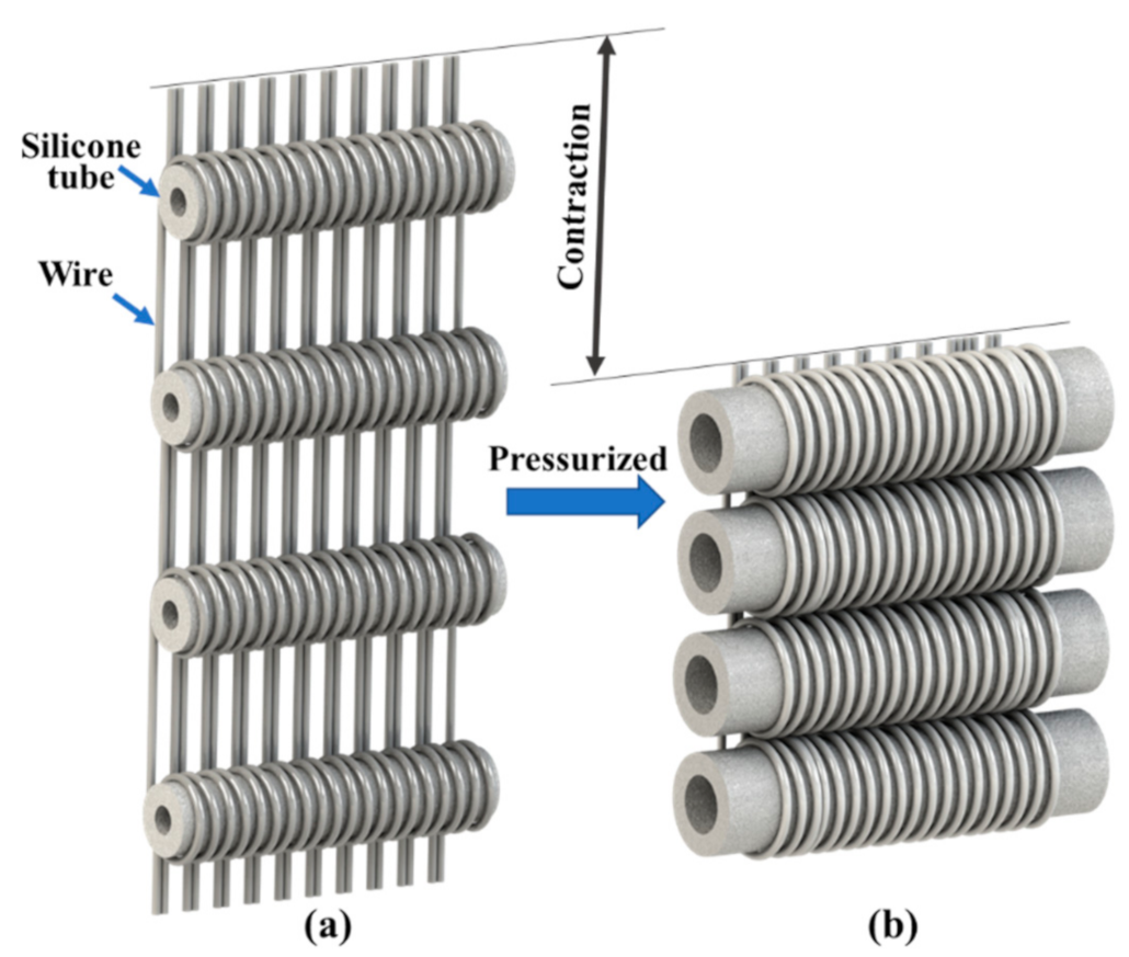
Hence, a novel winding method eliminating the disadvantages mentioned above is required. It is observed that the above winding methods are deployed when tubes are placed vertically. There is little discussion for now about the winding method when the tube is placed horizontally. The novel winding method in this paper is proposed based on this concept to design a novel horizontal placed pneumatic artificial muscle (HPAM), as shown in Figure 1. Compared with conventional PAMs, this winding method keeps inflation of tubes on one side of the actuator, avoiding interfering objects close to it. In this way, human compatibility can be improved, and the advantages of a soft actuator can be retained. We notice that the design proposed by Hiramitsu et al. [26] also discussed the state of tube placed horizontally whose winding method is a modification of the traditional weaving process. However, its wires are alternately distributed on both sides of the tubes, which still causes additional squeezing to the user when it is deployed in close fitting.
In this paper, first, the design concept of the PAM is introduced. Next, three winding methods are analyzed, and one method is chosen as the optimal method. Then, based on necessary simplification, the model of HPAM is proposed. The output characterization is tested and verifies the accuracy of the model. Finally, application in wearable robots is prospected.
2. Design Concept
As shown in Figure 1, the actuator is composed of several silicone tubes placed horizontally and wires winded densely. As tubes are pressurized and inflated, wires are dragged around pressurized tubes. Hence the overall HPAM contracts and produces contraction force. During this process, the inflation of tubes is limited on one side of the wires. The other side is not affected. In the prototype of this paper, the inner and outer diameters of tubes are 2 mm and 5 mm, respectively. The length of the silicone tubes is 30 mm.
It is worth noting that the winding pattern of HPAM is crucial for improving performance. In this paper, several winding patterns are provided and compared.
The first pattern is that all wires are winded in the same direction, as shown in Figure 2a. However, each wire around the tube produces a torque, and the overall actuator cannot be balanced. Hence the winding directions of two adjacent wires must be opposite, as shown in Figure 1. Another pattern is shown in Figure 2b. One end of the wire is passed through the gaps between the intertwined ones, which forms a circle that can be put in the silicone tube. This winding pattern is more stable because each wire is fixed into its places, avoiding interference among wires. However, hysteresis caused by friction appears more prominent in the experiment. Hence this paper uses the second method to manufacture the prototype.
3. Modeling
The contraction ratio model of HPAM is firstly analyzed. As shown in Figure 3a, the outer diameters of tube before and after pressurized are and ,espectively. The initial length of the actuator is defined as the distance between points at the bottom of the tubes. The length during contraction is . The contraction ratio of the actuator is as follows, where k = b/B. representing the inflation ratio of the tube:
Hence the contraction ratio is not affected by the initial outer diameter of the tube. The relation between the contraction ratio and inflation ratio is shown in Figure 3b. The plot shows that the contraction ratio increases fast with the inflation ratio at the first half of the plot and the increasing speed decreases with it, i.e., a large contraction ratio can be produced from a small strain. As the inflation ratio increases, the contraction ratio converges to 0.76.
Then the force model of HPAM is analyzed. Considering computational complexity, direct modeling requires calculating the effect of hyper-elasticity (silicone rubber), anisotropic (wires), and friction, which causes a decrease of convergence and an increase of computational complexity sharply. Therefore, it is necessary to simplify the model according to the experimental phenomena.
The output force of HPAM is composed of the force acting on wires by silicone tube and friction force between them. The two forces are coupled. However, the effect of silicone tube can be neglected because, through observation, the section of the silicone tube keeps round, as shown in Figure 3. Hence, to be approximate, the two forces can be decoupled and solved separately. The wires are densely winded, and the cross-section of the silicone tube is always circular. Therefore, the complicated expansion process of the silicone tube can be simplified into the free expansion under uniform pressure and on inner and outer walls, as shown in Figure 4b,c. Moreover, can be solved from , as shown in Figure 4a considering non-friction presumption where for force analysis, half of the wire is shown. Then the effect of friction between the outer wall and wires is added. The inner and outer radii of the tube before and after pressurized are , , , . Hence, by moment balance, the force is:
where is the length of winded part. Then, the friction force between the silicone tube and the wires is:
where is the friction coefficient between wires and tube obtained by experiment.
Then the output forces of the HPAM during contracting and stretching are:
In order to obtain the output force model, requires to be solved. The inflation of the silicone tube can be considered as a symmetric expansion of an infinite cylinder considering the low overall strain and it is assumed that the deformation law in cylindrical coordinate is:
where a point occupying position , , in the reference cylindrical configuration moves to position , , in the current configuration. and are circumferential and axial stretch, respectively.
The deformation gradient and the Green Strain take the following forms:
Then all components of Cauchy stress can be represented from and as following:
where is the strain energy defining on invariants. In this paper, the two-parameter Mooney-Rivlin model [27] is used for calculation because of the low maximum stretch whose parameters and are obtained from experiments.
Because of geometrical and constitutive symmetry, the only non-trivial component of the equilibrium equations is:
Integrate the equilibrium equation, and
over the wall thickness with account of the boundary conditions shown in Figure 4:
Through Equations (11)–(13), can be solved semi-analytically. Then substituting the value of Equations (4) and (5), the output force can be solved. The verification of the model is conducted in Section 5.
4. Fabrication
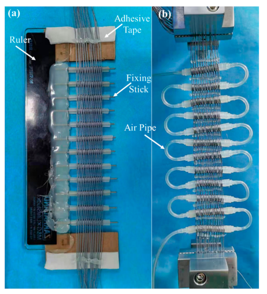
For the prototype design of this paper, a simple manual manufacturing board is designed as shown in Figure 5a. The board is composed of a ruler, several fixing sticks, and adhesive tapes. The fixing sticks support silicone tubes and fix their positions. These sticks can be glued on the setting positions accurately through the scale on the ruler by hot-melt adhesives. On the top and bottom of the ruler are the adhesive tapes, which can fix the wires. First, put the silicone tubes on the fixing sticks. Then fix one end of the wire on the adhesive tape, wrap it on silicone tubes one by one according to the winding pattern 2 described in Section 2. Stick the remaining wire on the adhesive tape at the bottom to complete the winding of the first wire. The rest wires are winded closely to each one as the above steps. When finishing the above steps, hot-melt adhesives are used to fix the ends of wires parallelly. Then remove the actuator from the board and install air pipes on silicone tubes. In this way, the actuator can be made as shown in Figure 5b. It is worth noticing that although the muscle is wider than tube-like traditional muscle, it can fit objects passively when both ends are fixed owing to its inherent compliance. This feature makes it perfect for wearable applications.
Considering the actuator life and contraction ratio, the prototype described in this paper is casted with silicone rubber of shore hardness 20 (Dragon Skin, Smooth-on). The diameter of wire is 0.2 mm. The length of winded part is 25 mm.
5. Experiment and Result
The experiment setup shown in Figure 6 was used to acquire output characteristics of HPAM. The actuator was fixed on the clamp of the force gauge and was slightly preloaded and straightened. It is worth noting that the ends of wires need to be paralleled, as shown in Figure 5b. Then, both force and displacement were set to zero on PC. The pressurized air was provided by an air compressor and adjusted by a pressure regulator (ITV1020, SMC). The current pressure of the system was acquired by a DAQ card (NI-6009) to be transmitted to the PC and be recorded. When the pressure reached desired value stably, the test bench drives HPAM slowly to move down (5 mm/min), simulating the quasi-static movement. Once the actuator reaches the shortest state, i.e., the output force equals zero, the force gauge moves up with the same speed to the initial position. This process was repeated at 3 pressures (100 kPa, 150 kPa, 200 kPa) 3 times to obtain the output characteristics of HPAM.
The output force corresponding to the contraction ratio at 3 different pressures were shown in Figure 7a. The actuator had a maximum contraction force of 12.24 N and a maximum contraction ratio of 35.8 % at 200 kPa. It is worth noting that the part where the data declines steeply was because that the output force was transiting from the state of stretching to , i.e., the state transition part. Figure 7b represents the comparison between the model and experiment result of the actuator at 2bar, which shows that lines of and acquired from model were slightly higher than the lines of stretching state and contraction state from the experiment. However, it was enough to verify the model proposed in Section 3. It is noted that the error of the model was lower when pressure increased from Figure 7b–d. This is because with the increase of pressure, the influence of friction on the state of silicone tubes decreased, hence the experiment result approached the model results.
According to the model, the output force was proportional to the length of the winded part . If the length of silicone tube was close to , the output force approaches the model. However, if the length of silicone tube much exceeds , the non-winded part at sides will expand freely, which affects the expansion of the winded part, thus affecting output.
The working efficiency of HPAM can be estimated from the Figure 7a by comparing the area under the contraction curve to the area under the stretch curve. The working efficiency of HPAM was about 45%. Friction accounts for the majority of hysteresis, thus affecting overall efficiency. However, the working efficiency can be improved from simply surface treatment. Further improvement will be conducted in a future study.
It is worth noting that if higher output force was needed in a limited area, increased diameter of silicone tubes could meet the demand. According to the model, the output force was positively related to pipe diameter, whereas the contraction ratio does not change with it, only with the inflation ratio, hence the output force can be easily increased without affecting the contraction ratio. Or the hardness of the material can be improved, thus that silicone tubes can bear higher air pressure, output force will also be increased. However, the inflation ratio of silicone tubes at the same pressure will be reduced, which will affect the contraction ratio at the same pressure.
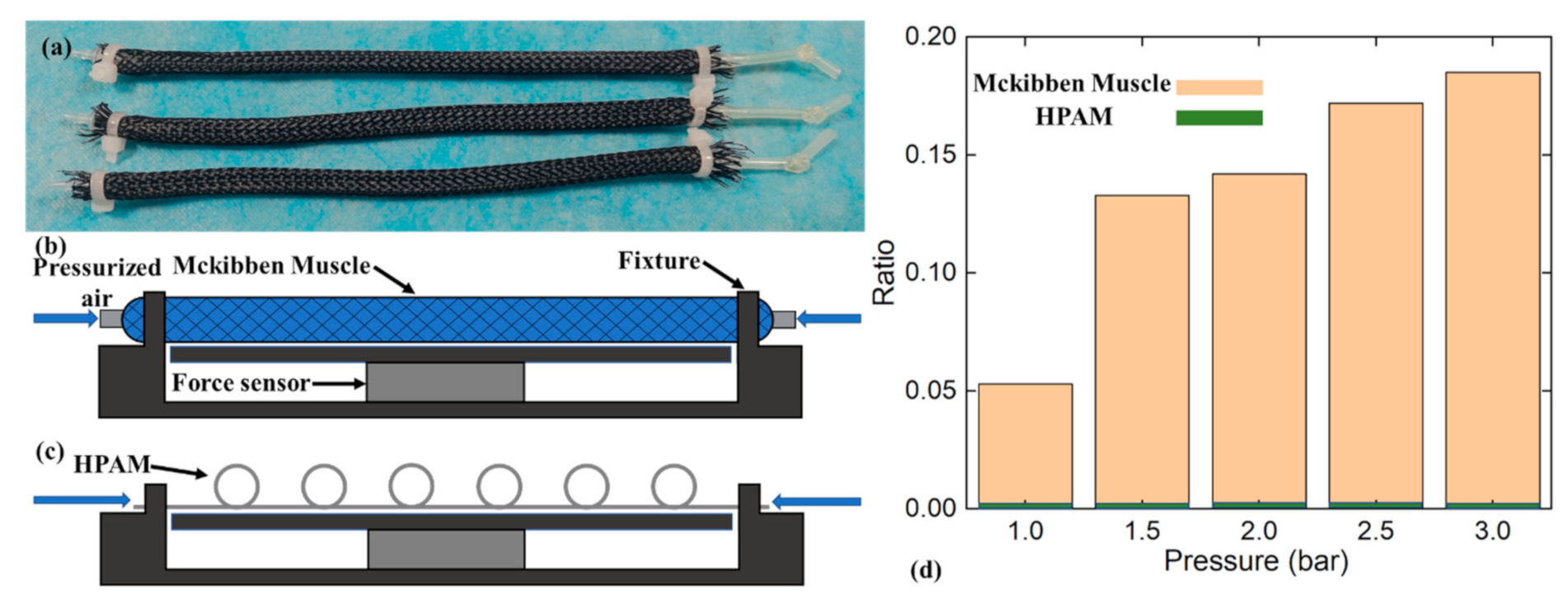
In order to verify the effect of HPAM on reducing the extra squeezing compared with traditional pneumatic muscles, three Mckibben muscles with the same length as HPAM were fabricated, as shown in Figure 8a. They were made of silicone tubes the same size as HPAM and wrapped with braided wires. The extra squeezing force was acquired on the test bench, as shown in Figure 8b,c. Mckibben muscles and HPAM were fixed on the fixture to the original length, and the force sensor under them can measure the extra squeezing force after pressurization. The ratio of extra squeezing force to output force at corresponding pressure is plotted as shown in Figure 8d. It can be seen that the ratio of Mckibben muscle gradually increased to 18.32% when pressure increased, which means that when the output force increased, the extra squeezing force increased faster. However, HPAM did not show obvious extra squeezing.
6. Conclusions and Discussion
This paper proposes a pneumatic artificial muscle based on a novel winding method (HPAM). The design and manufacturing method is introduced, and the output characteristics of HPAM are solved by simplified and semi-analytical methods. The output characteristic curve is obtained by experiment, and the accuracy of the model is verified. The maximum output force of HPAM is 12.24 N at 2 bar with a thickness of 5 mm. The maximum contraction ratio can reach 35.8 %.
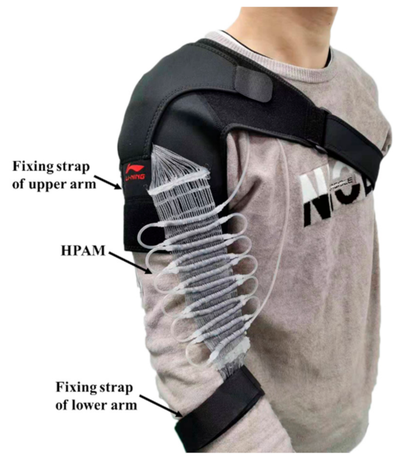
The winding method enables the inflation of silicone tubes on one side of wires avoiding interference of object close to it. HPAM is suitable for close-fitting without squeezing the skin of the user, as shown in Figure 9. With the 100 mm length of the winded part, the maximum output force reaches over 30 N with a thickness of 5 mm.
Considering the hysteresis caused by friction, future research will focus on reducing the hysteresis of the structure to improve energy efficiency. In addition, other types of silicone tubes will be considered, such as the fiber-reinforced type shown in [10], to improve overall performance.
Author Contributions
Conceptualization, writing—review and editing, investigation, validation, D.X.; modeling, Z.M.; supervision, J.L.; project administration, S.Z. All authors have read and agreed to the published version of the manuscript.
Funding
This research was in part funded by National Key R&D Program of China under Grant No. 2019YFB1311501, in part by National Natural Science Foundation of China under Grant No. 51905374 and 61773280.
Conflicts of Interest
The authors declare no conflict of interest.
References
- Zhou, L.; Ren, L.; Chen, Y.; Niu, S.; Han, Z.; Ren, L. Bio-Inspired Soft Grippers Based on Impactive Gripping. Adv. Sci. 2021, 8, 2002017. [Google Scholar] [CrossRef]
- Zahedi, A.; Zhang, B.; Yi, A.; Zhang, D. A Soft Exoskeleton for Tremor Suppression Equipped with Flexible Semiactive Actuator. Soft Robot 2020. [Google Scholar] [CrossRef] [PubMed]
- Rus, D.; Tolley, M.T. Design, fabrication and control of soft robots. Nature 2015, 7553, 467–475. [Google Scholar] [CrossRef] [PubMed] [Green Version]
- Lipson, H. Challenges and Opportunities for Design, Simulation, and Fabrication of Soft Robots. Soft Robot 2014, 1, 21–27. [Google Scholar] [CrossRef]
- Lee, J.; Rodrigue, H. Origami-Based Vacuum Pneumatic Artificial Muscles with Large Contraction Ratios. Soft Robot 2019, 1, 109–117. [Google Scholar] [CrossRef] [PubMed]
- Li, S.; Vogt, D.M.; Rus, D.; Wood, R.J. Fluid-driven origami-inspired artificial muscles. Proc. Natl. Acad. Sci. USA 2017, 50, 13132–13137. [Google Scholar]
- Byrne, O.; Coulter, F.; Glynn, M.; Jones, J.F.; Ní Annaidh, A.; O’Cearbhaill, E.D.; Holland, D.P. Additive Manufacture of Composite Soft Pneumatic Actuators. Soft Robot 2018, 6, 726–736. [Google Scholar] [CrossRef] [PubMed]
- Franco, W.; Maffiodo, D.; De Benedictis, C.; Ferraresi, C. Use of McKibben Muscle in a Haptic Interface. Robotics 2019, 1, 13. [Google Scholar] [CrossRef] [Green Version]
- Martens, M.; Boblan, I. Modeling the Static Force of a Festo Pneumatic Muscle Actuator: A New Approach and a Comparison to Existing Models. Actuators 2017, 4, 33. [Google Scholar] [CrossRef] [Green Version]
- Connolly, F.; Polygerinos, P.; Walsh, C.J.; Bertoldi, K. Mechanical Programming of Soft Actuators by Varying Fiber Angle. Soft Robot 2015, 1, 26–32. [Google Scholar]
- Singh, G.; Krishnan, G. Designing Fiber-Reinforced Soft Actuators for Planar Curvilinear Shape Matching. Soft Robot 2020, 1, 109–121. [Google Scholar] [CrossRef]
- Sangian, D.; Jeiranikhameneh, A.; Naficy, S.; Beirne, S.; Spinks, G.M. Three-Dimensional Printed Braided Sleeves for Manufacturing McKibben Artificial Muscles. 3D Print. Addit. Manuf. 2019, 1, 57–62. [Google Scholar] [CrossRef]
- Hawkes, E.W.; Christensen, D.L.; Okamura, A.M. Design and implementation of a 300% strain soft artificial muscle. In Proceedings of the 2016 IEEE International Conference on Robotics and Automation (ICRA), Stockholm, Sweden, 16–21 May 2016; pp. 4022–4029. [Google Scholar]
- Kurumaya, S.; Nabae, H.; Endo, G.; Suzumori, K. Design of thin McKibben muscle and multifilament structure. Sens. Actuat. A Phys. 2017, 66–74. [Google Scholar] [CrossRef]
- Kurumaya, S.; Suzumori, K.; Nabae, H.; Wakimoto, S. Musculoskeletal lower-limb robot driven by multifilament muscles. Robomech J. 2016, 3, 18. [Google Scholar] [CrossRef] [Green Version]
- Abe, T.; Koizumi, S.; Nabae, H.; Endo, G.; Suzumori, K.; Sato, N.; Adachi, M.; Takamizawa, F. Fabrication of “18 Weave” Muscles and Their Application to Soft Power Support Suit for Upper Limbs Using Thin McKibben Muscle. IEEE Robot Autom. Let. 2019, 3, 2532–2538. [Google Scholar] [CrossRef]
- Jiang, Y.; Chen, D.; Liu, C.; Li, J. Chain-Like Granular Jamming: A Novel Stiffness-Programmable Mechanism for Soft Robotics. Soft Robot 2019, 1, 118–132. [Google Scholar] [CrossRef]
- Li, Y.; Chen, Y.; Ren, T.; Li, Y.; Choi, S.H. Precharged Pneumatic Soft Actuators and Their Applications to Untethered Soft Robots. Soft Robot 2018, 5, 567–575. [Google Scholar] [CrossRef]
- Wang, Z.; Wang, D.; Zhang, Y.; Liu, J.; Wen, L.; Xu, W.; Zhang, Y. A Three-Fingered Force Feedback Glove Using Fiber-Reinforced Soft Bending Actuators. IEEE Trans. Ind. Electron. 2020, 9, 7681–7690. [Google Scholar] [CrossRef]
- Wirekoh, J.; Parody, N.; Riviere, C.N.; Park, Y.L. Design of fiber-reinforced soft bending pneumatic artificial muscles for wearable tremor suppression devices. Smart Mater. Struct. 2020, 1, 015013. [Google Scholar]
- Polygerinos, P.; Wang, Z.; Galloway, K.C.; Wood, R.J.; Walsh, C.J. Soft robotic glove for combined assistance and at-home rehabilitation. Robot Auton. Syst. 2015, 135–143. [Google Scholar] [CrossRef] [Green Version]
- Thakur, C.; Ogawa, K.; Tsuji, T.; Kurita, Y. Soft Wearable Augmented Walking Suit With Pneumatic Gel Muscles and Stance Phase Detection System to Assist Gait. IEEE Robot Autom. Let. 2018, 4, 4257–4264. [Google Scholar] [CrossRef]
- Park, Y.L.; Santos, J.; Galloway, K.G.; Goldfield, E.C.; Wood, R.J. A Soft Wearable Robotic Device for Active Knee Motions using Flat Pneumatic Artificial Muscles. In Proceedings of the IEEE International Conference on Robotics and Automation ICRA, Hong Kong, China, 31 May–7 June 2014; pp. 4805–4810. [Google Scholar]
- Kojima, A.; Okui, M.; Hisamichi, I.; Tsuji, T.; Nakamura, T. Straight-Fiber-Type Artificial Muscle Deformation Under Pressurization. IEEE Robot Autom. Let. 2019, 3, 2592–2598. [Google Scholar] [CrossRef]
- Koizumi, S.; Chang, T.H.; Nabae, H.; Endo, G.; Suzumori, K.; Mita, M.; Saitoh, K.; Hatakeyama, K.; Chida, S.; Shimada, Y. Soft Robotic Gloves with Thin McKibben Muscles for Hand Assist and Rehabilitation. In Proceedings of the 2020 IEEE/SICE International Symposium on System Integration, Honolulu, HI, USA, 12–15 January 2020; pp. 93–98. [Google Scholar]
- Hiramitsu, T.; Suzumori, K.; Nabae, H.; Endo, G. Experimental Evaluation of Textile Mechanisms Made of Artificial Muscles. In Proceedings of the IEEE International Conference on Soft Robotics (RoboSoft), Seoul, Korea, 14–18 April 2019; pp. 1–6. [Google Scholar] [CrossRef]
- Mooney, M. A Theory of Large Elastic Deformation. J. Appl. Phys. 1940, 9, 582–592. [Google Scholar] [CrossRef]
Figure 1.
Three-dimensional diagram of the initial state (a) and contraction state (b) of HPAM, air pipes, and the side of silicone tubes are hidden for clearer display.
Figure 1.
Three-dimensional diagram of the initial state (a) and contraction state (b) of HPAM, air pipes, and the side of silicone tubes are hidden for clearer display.

Figure 2.
Two patterns of winding (a) in same direction (b) one end of wire is passed through the gaps between the intertwined wire.
Figure 2.
Two patterns of winding (a) in same direction (b) one end of wire is passed through the gaps between the intertwined wire.

Figure 3.
(a) The contraction ratio model of HPAM (b) the plot of inflation ratio changing with contraction ratio.
Figure 3.
(a) The contraction ratio model of HPAM (b) the plot of inflation ratio changing with contraction ratio.

Figure 4.
(a) For elucidation and force analysis, half of the wire is shown considering non-friction presumption. Sectional view of pipe before (b) and after (c) pressurized.
Figure 4.
(a) For elucidation and force analysis, half of the wire is shown considering non-friction presumption. Sectional view of pipe before (b) and after (c) pressurized.

Figure 5.
(a) Manufacturing board of HPAM (b) picture of HPAM fixed on the clamp of the test bench.

Figure 6.
Test bench to acquire output characteristics.

Figure 7.
(a) Output characteristics of HPAM at three pressures, (b) comparison between data of model and experiment at 2.0 bar, (c) comparison between data of model and experiment at 1.5 bar, (d) comparison between data of model and experiment at 1.0 bar.
Figure 7.
(a) Output characteristics of HPAM at three pressures, (b) comparison between data of model and experiment at 2.0 bar, (c) comparison between data of model and experiment at 1.5 bar, (d) comparison between data of model and experiment at 1.0 bar.

Figure 8.
(a) Three Mckibben muscles with an outer and inner diameter of 5 mm and 2 mm, respectively, (b) Mckibben muscles are fixed on a test bench to obtain extra squeezing force, (c) HPAM is fixed on a test bench to obtain extra squeezing force, (d) the plot of extra squeezing force to output force ratio changing with pressure.

Figure 9.
HPAM with 100 mm length of the winded part is fixed on the arm through upper and lower fixing strap to assist movement.
Figure 9.
HPAM with 100 mm length of the winded part is fixed on the arm through upper and lower fixing strap to assist movement.

Publisher’s Note: MDPI stays neutral with regard to jurisdictional claims in published maps and institutional affiliations. |
© 2021 by the authors. Licensee MDPI, Basel, Switzerland. This article is an open access article distributed under the terms and conditions of the Creative Commons Attribution (CC BY) license (https://creativecommons.org/licenses/by/4.0/).
Share and Cite
MDPI and ACS Style
Xie, D.; Ma, Z.; Liu, J.; Zuo, S. Pneumatic Artificial Muscle Based on Novel Winding Method. Actuators 2021, 10, 100. https://0-doi-org.brum.beds.ac.uk/10.3390/act10050100
AMA Style
Xie D, Ma Z, Liu J, Zuo S. Pneumatic Artificial Muscle Based on Novel Winding Method. Actuators. 2021; 10(5):100. https://0-doi-org.brum.beds.ac.uk/10.3390/act10050100
Chicago/Turabian StyleXie, Disheng, Zhuo Ma, Jianbin Liu, and Siyang Zuo. 2021. "Pneumatic Artificial Muscle Based on Novel Winding Method" Actuators 10, no. 5: 100. https://0-doi-org.brum.beds.ac.uk/10.3390/act10050100
Note that from the first issue of 2016, this journal uses article numbers instead of page numbers. See further details here.