Article

Fuzzy Supervisory Passivity-Based High Order-Sliding Mode Control Approach for Tidal Turbine-Based Permanent Magnet Synchronous Generator Conversion System

by
Youcef Belkhier
1,
Abdelyazid Achour
1,
Rabindra Nath Shaw
2,
Nasim Ullah
3,
Md. Shahariar Chowdhury
4 and
Kuaanan Techato
4,5,*
1
Laboratoire de Technology Industrielle et de l’Information (LTII), Faculté de Technologie, Université de Bejaia, Bejaia 06000, Algeria
2
Department of Electronics & Communication Engineering, Galgotias University, Greater Noida 201306, India
3
Department of Electrical Engineering, College of Engineering, Taif University, P.O. Box 11099, Taif 21944, Saudi Arabia
4
Faculty of Environmental Management, Prince of Songkla University, Hat Yai 90112, Thailand
5
Environmental Assessment and Technology for Hazardous Waste Management Research Center, Faculty of Environmental Management, Prince of Songkla University, Hat Yai 90112, Thailand
*
Author to whom correspondence should be addressed.
Submission received: 17 March 2021 / Revised: 21 April 2021 / Accepted: 22 April 2021 / Published: 27 April 2021
(This article belongs to the Section Control Systems)

Abstract

:
Higher efficiency, predictability, and high-power density are the main advantages of a permanent magnet synchronous generator (PMSG)-based hydro turbine. However, the control of a PMSG is a nontrivial issue, because of its time-varying parameters and nonlinear dynamics. This paper suggests a novel optimal fuzzy supervisor passivity-based high order sliding-mode controller to address problems faced by conventional techniques such as PI controls in the machine side. An inherent advantage of the proposed method is that the nonlinear terms are not canceled but compensated in a damped way. The proposed controller consists of two main parts: the fuzzy gain supervisor-PI controller to design the desired dynamic of the system by controlling the rotor speed, and the fuzzy gain-high order sliding-mode control to compute the controller law. The main objectives are feeding the electrical grid with active power, extracting the maximum tidal power, and regulating the reactive power and DC voltage toward their references, whatever the disturbances caused by the PMSG. The main contribution and novelty of the present work consists in the new robust fuzzy supervisory passivity-based high order sliding-mode controller, which treats the mechanical characteristics of the PMSG as a passive disturbance when designing the controller and compensates it. By doing so, the PMSG tracks the optimal speed, contrary to other controls which only take into account the electrical part. The combined high order sliding-mode controller (HSMC) and passivity-based control (PBC) resulted in a hybrid controller law which attempts to greatly enhance the robustness of the proposed approach regardless of various uncertainties. Moreover, the proposed controller was also validated using a processor in the loop (PIL) experiment using Texas Instruments (TI) Launchpad. The control strategy was tested under parameter variations and its performances were compared to the nonlinear control methods. High robustness and high efficiency were clearly illustrated by the proposed new strategy over compared methods under parameter uncertainties using MATLAB/Simulink and a PIL testing platform.

1. Introduction

With advantages such as long-term predictability, tidal renewable energy has gained increasing interest in the research community and it has emerged as a viable clean renewable power source to harness tidal power. Marine current turbines have been proposed and tested by researchers and industry developers. A PMSG-based marine current conversion system with grid connection via back-to-back converter has become the most widely utilized option in the tidal power industry due to its low cost and high-power density [1,2]. PMSGs are very interesting for this type of underwater application, where access to maintenance operations is often a critical and challenging task. For direct drive systems, the generator is directly connected to the turbine and the assembly rotates at the same speed. Therefore, the generator is driven at low speed and the mechanical speed multiplier is eliminated. Thus, the efficiency of the conversion system is improved and the maintenance cost required, mainly due to the gearbox, is minimized. However, without a proper control strategy, this type of configuration presents several drawbacks such as poor power quality integration to the grid due to disturbances caused by the PMSG, the reactive power and the harmonics generated by the rectifier in the AC side, rippled DC output at the DC side, poor power factor at the power supply side, and voltage distortion. Moreover, these systems are not yet massively deployed as they are facing reliability and availability challenges generally caused by the harsh marine environment [3,4]. Thus, it is necessary to design an appropriate controller that addresses the aforementioned issues. During recent decades, extensive control theories and techniques have been reported in the literature proposing solutions to the stated PMSG problems. In [5], a Jaya-based sliding mode approach is proposed to enhance the performances of a tidal conversion system. The authors proposed an association of the tidal system with a superconducting magnetic energy system (SCMES), to which the Jaya-based controller is applied. This association improves the costs and maintenance time of the conversion system. In [6], a fuzzy sliding mode controller was developed. However, system parameter changes and uncertainties have not been considered. Authors in [7] proposed a novel active disturbance rejection controller as an alternative to the conventional PI control. This strategy treats the parameter uncertainties or changes as an element to be rejected, which can be canceled during the control design. A magnetic equivalent circuit method-based second-order sliding mode is proposed in [8]. However, external disturbances and parameter changes have not been considered. In order to extract the maximum power from tidal currents under large parametric uncertainties and in the presence of nonlinearities, a nonlinear observer-based second-order SMC combined with a predictive control was developed in [9]. A linear quadratic controller is proposed in [10] using a real profile of the tidal current speed. In [11], a “perturb and observe” algorithm is proposed to track the maximum tidal power. Tilt-based fuzzy cascaded control combined with a new Q-network algorithm has been investigated by [12]. An adaptive super twisting algorithm combined with a high order sliding-mode approach is proposed in [13]. An economic model predictive controller is investigated in [14] to enhance the power generated by the conversion system.
Nevertheless, the aforementioned theories and techniques generally omit the PMSG physical properties during the control design. This work presents a novel controller method, based on the passivity principle that tracks velocity and maintains the operating torque at the optimal values. Inherent advantages of the passivity-based control (PBC) method include the following: nonlinear terms are not cancelled but compensated in a damped way, and the guaranteed robustness properties ensure stability. The main idea of this approach is to reshape the system’s natural energy and inject the required damping in such a way that the control objective is achieved [15]. A fuzzy logic controller and high order sliding-mode controller (HSMC) are adopted using the PBC method to design the desired dynamics and to formulate the final control law, respectively. The proposed method enhances the robustness regardless of the external disturbances and parameter uncertainties associated with the PMSG. It also ensures fast convergences of the measured signals toward their set values and guarantees high stability. The system dynamic is decomposed as a feedback interconnection of one electrical and one mechanical passive system. The developed strategy is applied to the electrical subsystem, leaving the feedback mechanical subsystem as passive perturbation, unlike the aforementioned nonlinear control methods, which are usually signal-based, and neglecting the PMSG mechanical part [16]. In [17], a PBC associated with a sliding-mode control (SMC) is proposed. As mentioned by the authors, the presented combined PBC-SMC control uses more than six fixed gains and it is very difficult to determine their optimal values. In fact, as demonstrated by Zhou et al., in [7], fixed gains are very difficult to calculate if the controller system is exposed to parameter variations or uncertainties. The authors in [18] investigated a passivity-based control combined with a fuzzy control and SMC by constructing a suitable fuzzy function. However, the controller design of the proposed combined strategy is complicated due to the mathematical model, which is very complex. In [19], a PBC with a linear feedback controller is investigated. However, parameter uncertainties of the PMSG have not been considered. In [20], a new PBC combined control is proposed. The PBC combined controller consists of two approaches, namely standard passivity-based control and PI-passive. A passivity-based voltage control is developed in [21]; however, as mentioned, the new controller shows little sensitivity to the variation of the mechanical parameters. A passivity-based control with asymptotic convergence of the states is discussed in [22]. The same system was considered in [23]. A PI-PBC is adopted to control the coupling phenomena of the PMSG. In [24], a robust adaptive passivity-based control scheme for a class of open-loop unstable nonlinear systems with actuator saturation is proposed. Passivity-based control has also been applied in doubly fed induction generator-based renewable energy conversion systems [25]. Similarly, an interconnection and damping assignment PBC is investigated in [26], while a robust passivity-based nonlinear observer and energy reshaping is proposed in [27]. The PBC can also be found in other engineering applications such as in smart grids [28], buildings [29], cyber-physical systems [30] and electric vehicles [31].
Maximum power extraction from the tidal turbine, by taking into account its entire dynamics when synthesizing the controller, represents the main motivation of the present work. The other aims of the study consist in maintaining the generated reactive power and DC-link voltage at their reference values, despite the disturbances related to the PMSG system. The goal is to improve the overall performance of the tidal conversion system, with a special focus on the generator control, as it is the bridge between the tidal turbine and the grid. Furthermore, the robustness against parameter changes has been taken into consideration.
This paper is inspired by [15], where the objective is to control the permanent magnet synchronous generator using the passivity-based current control approach. The contributions of this article are as follows:
  • A new robust fuzzy supervisory passivity-based high order sliding-mode control strategy is investigated for a PMSG in a grid-connected hydro conversion system.
  • The developed controller treats the mechanical characteristics of the PMSG as a passive disturbance when designing the controller and compensates it. By doing so, the PMSG tracks the optimal speed, contrary to other controls which only take into account the electrical part.
  • A high order sliding-mode controller (HSMC) is combined with PBC to design a hybrid controller law for enhancing the robustness of the proposed approach regardless of various uncertainties.
  • A fuzzy gain supervisor method is incorporated into the PBC design to control the PMSG speed and approximate its unstructured dynamics.
The rest of this paper is organized as follows. The mathematical description of the tidal system is given in Section 1. The computation of the new proposed strategy is demonstrated in Section 2. Section 3 deals with the grid-side converter (GSC) control strategy. Section 4 discusses the numerical results obtained. Finally, the main conclusions are given in Section 5.

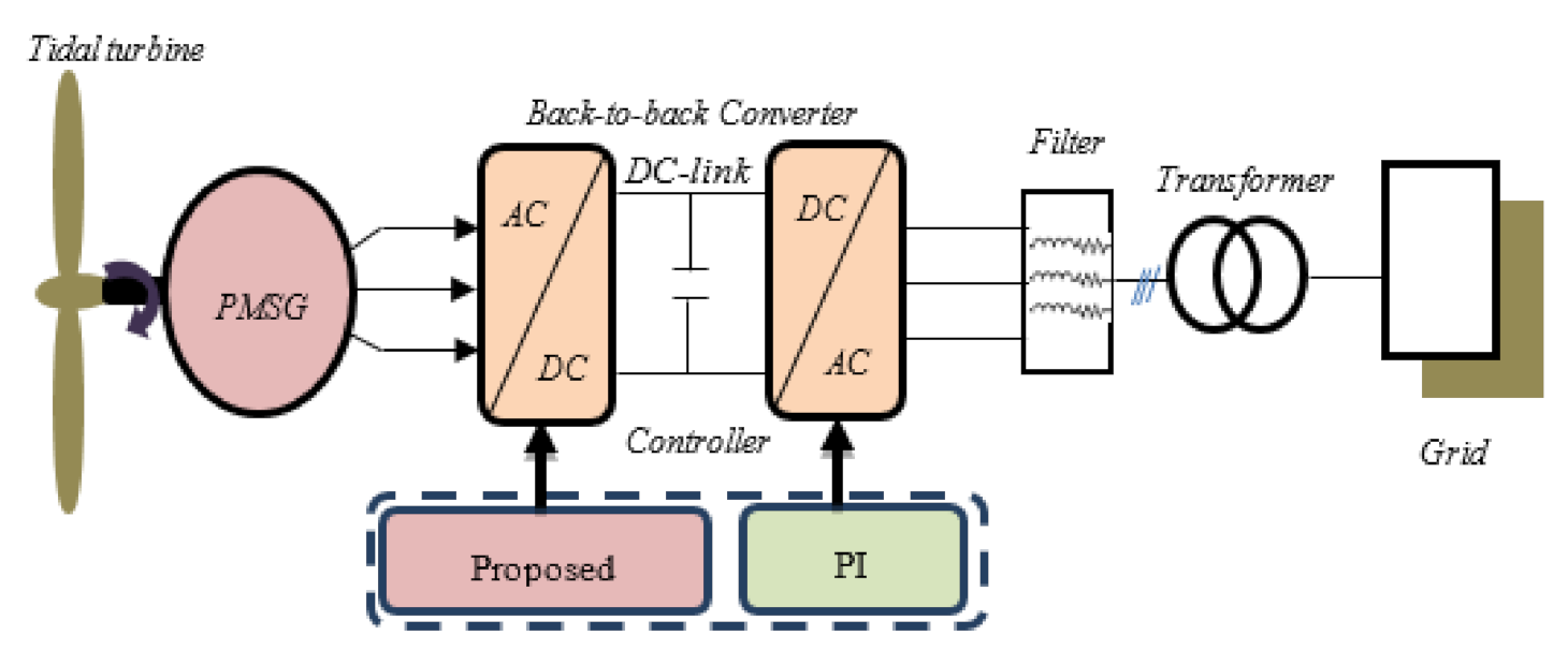
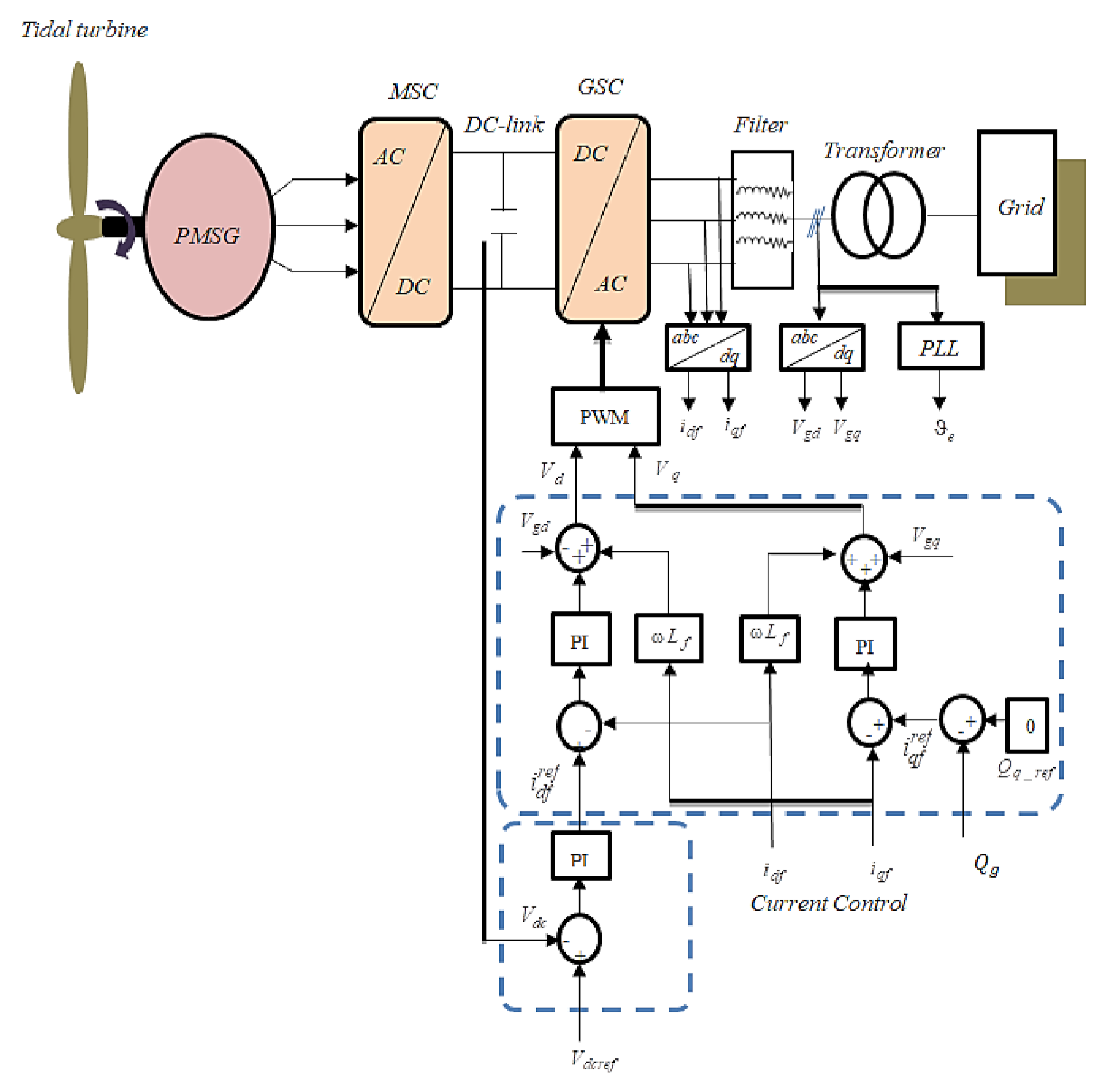
2. Hydro Conversion System Configuration

The investigated power conversion system consists of a tidal turbine, PMSG, AC-DC-AC power converter, and the grid. The power produced via the generator is controlled by the proposed nonlinear controller applied to the machine side converter, while delivering only active power is the principal aim of the GSC controller. The block diagram of tidal wave conversion system is shown in Figure 1.

2.1. Hydro Power

The tidal power captured by the turbine and the corresponding torque are expressed as below [4,17]:
P m = 1 2 ρ C p β , λ Av t 3
T m = P m ω t
C p β , λ = 0.5 116 λ i 0.4 β 5 e 21 λ i
λ i 1 = λ + 0.08 β 1 0.035 1 + β 3 1
λ = ω t R v t
where β denotes the pitch angle, v t is the tidal speed, ρ represents water density, λ denotes tip-speed ratio, C p represents the power coefficient, A denotes the swept area of the blades, R denotes the radius of the blades, and   ω t represents the speed of the turbine.

2.2. PMSG Model

The dq-model of the PMSG is given as follows [15,32]:
v dq = R dq i dq + L dq di dq dt + p ω m ( L dq i dq + ψ f )
J d ω m dt = T m T e f fv ω m
T e = 3 2 p ψ dq i dq
where ω m represents the speed of the PMSG, ψ f = ϕ f 0 represents the vector of the flux linkages, i dq = i d i q represents the vector of the stator currents, T e is the electromagnetic torque, R dq = R S 0 0 R s represents the matrix of the stator resistance, J denotes the total inertia of the system, v dq = v d v q denotes the vector of the voltage stator, = 0 1 1 0 , L dq = L d 0 0 L q denotes the matrix of the stator inductions and f fv is the viscous coefficient.

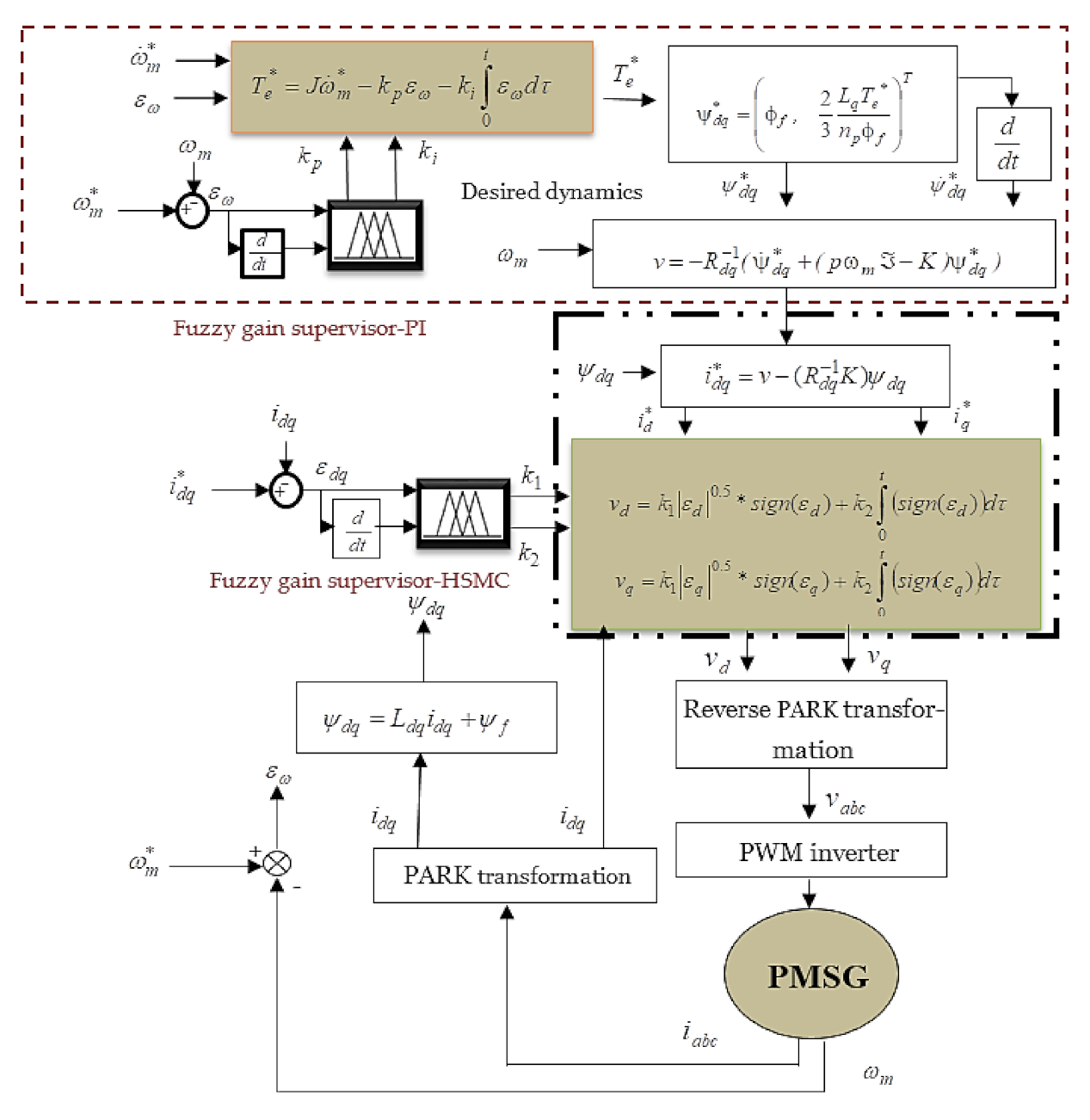
3. PMSG Proposed Controller Structure

In order to apply the passivity-based control to rotating electrical machines such as the PMSG and the DFIG, a number of steps are needed. First, it is necessary to calculate a Euler–Lagrange model, and to choose appropriate input and output vectors such that the relationship between them is passive. Second, the system has to be decomposed into two interconnected subsystems with negative feedback. Finally, the last step consists of identifying the non-dissipative terms in the system model. For more details about the application of the PBC for these rotating machines and the control design process, the reader is referred to [33]. The controller design process is depicted in Figure 2. Two main parts can be distinguished for the application of the optimal fuzzy supervisory passivity-based high order sliding-mode controller (OFSP-HSMC) proposed in this work. The first step is the computation of the reference electromagnetic torque, computed by the fuzzy supervisory-PI controller (FS-PI). The reference torque designs the desired current. The second part computes the control voltage using the fuzzy supervisory-HSMC (FS-HSMC) controller. Making the system passive and forcing the PMSG to track tidal turbine speed is the principal aim of the proposed method. This is possible by reshaping its energy and introducing a damping term.

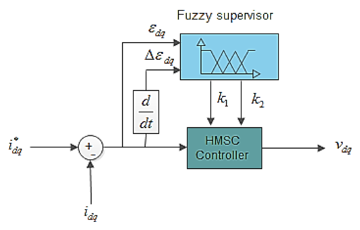
3.1. Current Controller with Fuzzy Supervisory-HSMC

As proposed in [15], a PI voltage controller v dq is designed for current tracking of i dq to accurately follow its set vector i dq * = i d * i q * . However, PI control is generally not robust against parameter changes and uncertainties, due to its fixed gains [7]. Thus, a high order sliding-mode controller (HSMC) is introduced to replace the PI loop. It is well known that this control has high-properties of robustness and stability as compared to the PI controls [34]. In fact, the sliding-mode control belongs to the family of variable structure controllers; i.e., controls that switch between several different control laws. The importance of sliding-mode controllers lies in their high accuracy, fast dynamic response, stability, simplicity of design and implementation, and robustness due to parameter changes and external disturbances. Then, the voltage controller v dq is expressed as below:
v d = k 1 ε d 0.5 sign ε d + k 2 0 t sign ε d d τ
v q = k 1 ε q 0.5 sign ε q + k 2 0 t sign ε q d τ
where k 1 > 0 , k 2 > 0 . ε dq = ε d ε q = i d * i d i q * i q represents the currents error vector. However, the sliding mode in practice induces high frequency switching known as “chattering”. These switches can excite unwanted dynamics that can destabilize, deteriorate or even destroy the system under study. Thus, to address the chattering phenomenon, the high order sliding mode has been adopted, whose principle is to reject discontinuities in the higher derivatives of the system input [7] and [8]. Moreover, to overcome the gain sensitivity to the parameter uncertainties and for an optimal voltage controller of the PMSG, a fuzzy gain supervisor is adopted, as shown in Figure 3.
The fuzzy supervisor is used to adjust the HSMC gains k 1 and k 2 and it solves the problem caused by imprecise parameters, where the inputs to the fuzzy system are chosen as the currents error ε dq and its derivative   ε dq . The fuzzy controller design procedure has three steps: fuzzification, rule base, and defuzzification. The types of the membership functions used are triangular and trapezoidal; that is, uniformly distributed and symmetrical in the universe of discourse (see Figure 4). The method of partitioning these functions is given according to the method reported by Lee and Yubaziki [35,36]. This method is based on the idea of sharing the same parameters by several membership functions. The advantage of this method is that the number of parameters of the membership functions is significantly reduced. In Table 1, the linguistic variables corresponding to the inputs–outputs of the fuzzy gain scheduling are chosen as: negative big (NB), negative small (NS), zero (Z), positive big (PB), and positive small (PS). The defuzzification step is performed by using the center of gravity method. The design of the controller law with the proposed combined fuzzy supervisory-HSMC is illustrated in Figure 3.
The aim is to design the control inputs i dq * using a passivity concept that guarantees the convergence of the currents error vector ε dq . This results in the desired dynamics of the PMSG model expressed by:
d ψ dq dt p ω m ψ dq = v dq R s
J d ω m dt = T m T e f fv ω m
T e = 3 2 p ψ dq T i dq *

3.2. Passivity-Based Current Controller

The flux tracking error is given as follows:
e f = e fd e fq T = ψ dq ψ dq *
where ψ dq * = ψ d * ψ q * T denotes the desired value of the flux linkages vector. By substituting (8) in (11) and considering the Lyapunov function V e f = 0.5 e f T e f , the control signals i dq * = i d * i q * T which guarantees the convergence of the flux linkage tracking error, e f , is expressed below:
i dq * = R s 1 d ψ dq * dt + p ω m ψ dq * K f e f
where K f = K fd 0 0 K fq , K fd > 0 , and K fq > 0 ψ dq * . The proof of the exponential convergence of the flux tracking error and current tracking error is given in Appendix A.
The interdependence between the induced flux linkage in the PMSG ψ dq and the currents vector i dq is given by [15,32]:
ψ dq = ψ d ψ q = L d i d + ϕ f L q i q
where ϕ f represents the flux linkages due to the permanent magnets. The PMSG works at maximum torque if the direct axis current is maintained to zero. The flux ψ d is reduced to the flux ϕ f . Thus, the desired flux linkages are given below:
ψ dq = ψ d * ψ q * = ϕ f L q i d *
From (13) and (17), the desired flux along q-axis is given by:
ψ q * = 2 3 L q p ϕ f T e *

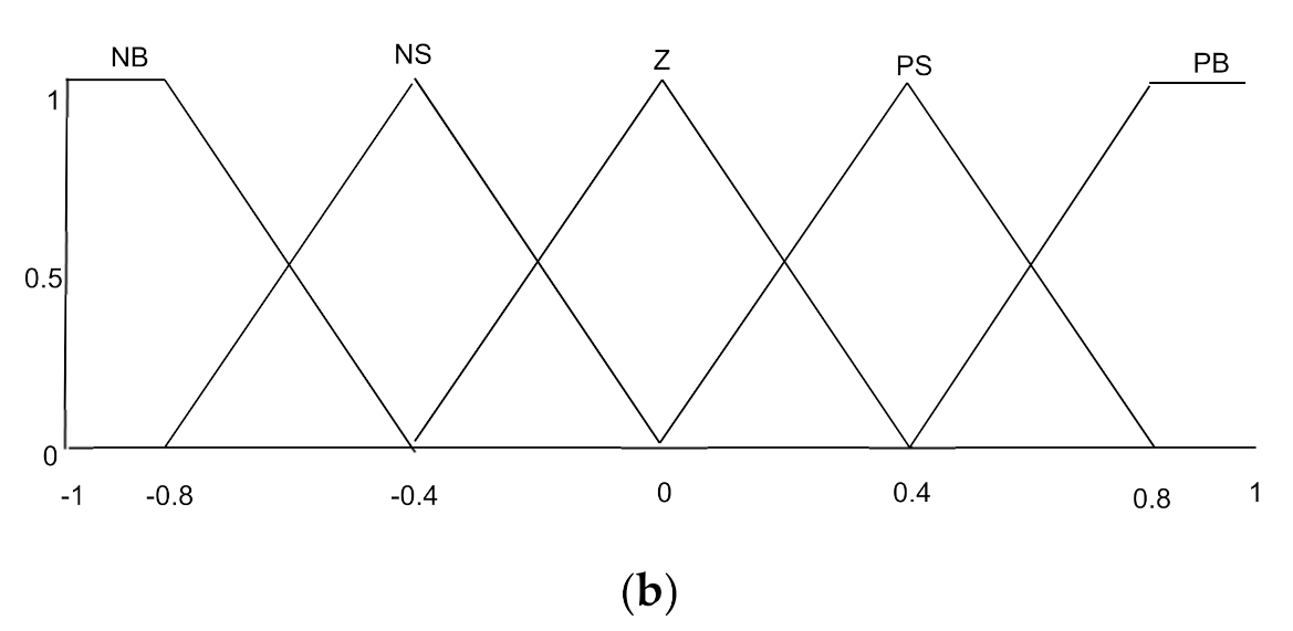
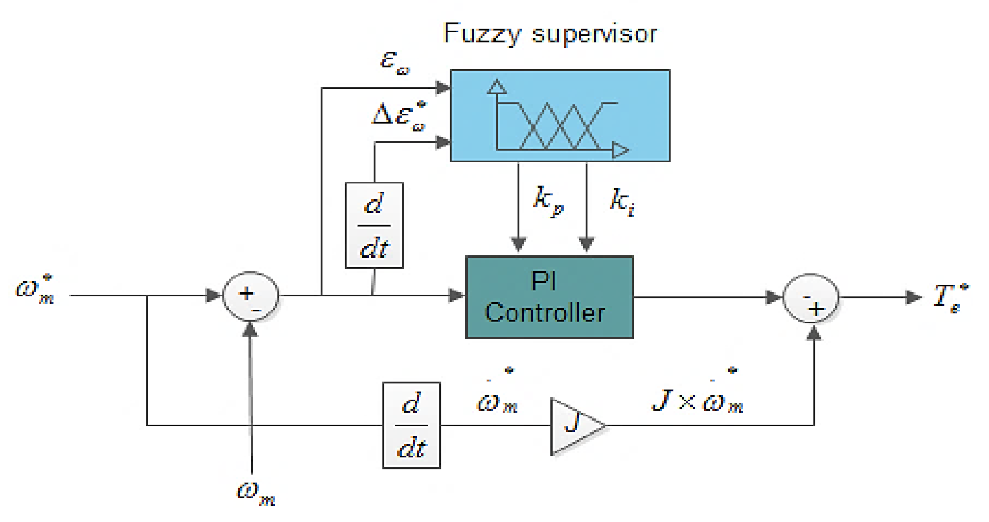
3.3. Desired Torque Design with Fuzzy Supervisory-PI Controller

The desired torque is deduced from the mechanical dynamic Equation (13), which is expressed by:
T e * = J d ω m * dt f fv ω m * ω m
The goal is to minimize the speed error between the PMSG and the marine current turbine. As can be seen from the above Equation (19), the desired torque T e * has two drawbacks: its convergence depends on the parameters ( J , f fv ) and it is an open loop. To overcome the mentioned problems, a PI controller is adopted and combined with the proposed fuzzy supervisor. Fuzzy supervisors eliminate the static error, ensure robustness under different operation conditions, adjust the gains, k p and k i , of the PI controller, and guarantee a fast convergence of the speed error ,   ε ω = ω m * ω m . The inputs of the fuzzy system are the speed error ε ω and its derivative ε ω , and the outputs are the PI gains k p and   k i .
The fuzzy rules of this controller are the same as for the fuzzy supervisor-HSMC in Section 3.1. In Table 1, the set of fuzzy rules are defined for the fuzzy gains supervisor-PI and the fuzzy gains supervisor-HSMC [37]. The fuzzy inference method used is the Mamdani type. The decision-making outputs are obtained using a minimum–maximum fuzzy inference where the crisp outputs are calculated by the center of gravity defuzzification method.
T e * is calculated as:
T e * = J d ω m * d τ k p ε ω k i 0 t ε ω d τ
where k p > 0, and k i > 0. The design of the desired torque with the proposed combined fuzzy supervisory-PI controller is illustrated in Figure 5. The proof of the global stability of the closed-loop system is given in Appendix B and the proof of the passivity property of the PMSG using the Euler–Lagrange model is given in Appendix C.

4. GSC Controller

Figure 6 depicts the conventional PI strategy used to control the GSC converter. The mathematical model of the GSC converter is expreseed below [7,32,38]:
v d v q = R f i df i qf + L f di df dt ω L f i qf L f di qf dt + ω L f i df + v gd v gq
where v gd and v gq are the grid voltages, i df and i qf are the grid currents, v d and v q denote the inverter voltages, ω denotes the network angular frequency, R f represents the filter resistance, and L f is the filter inductance. The DC voltage model is given as below:
C dV dc dt = 3 2 v gd V dc i df + i dc
where C denotes the DC-link capacitance, i dc represents the grid side line current, and V dc denotes the DC-link voltage. The current PI loop is given as:
v gd PI = k gp d i df ref i df k gi d 0 t i df ref i df d τ v gq PI = k gp q i qf ref i qf k gi q 0 t i qf ref i qf d τ
where k gp d > 0 , k gi d > 0 , k gp q > 0 , k gi q > 0 . The q-axis current i qf ref PI is expressed by:
i qf ref = k dcp V dc _ ref V dc k dci 0 t V dc _ ref V dc d τ
where k dcp > 0 and   k dci > 0 . Finally, the reactive power and active power are given by:
P g = 3 2 v gd i df Q g = 3 2 v gd i qf

5. Numerical Validation

In this section, a 1.5 MW PMSG-based tidal conversion system is studied, the reference reactive power is fixed to zero and the DC-link reference is set to 1150 V. The tidal turbine parameters can be found in [39]; the PMSG and grid-side data are given in [40,41]. The system parameters are tabulated in Table 2. The initial conditions used in simulation are as follows: k fq = 100 , [ ω m 0 , i dq 0 = 0 , 0 , 0 ] for the PMSG, Vdc (0) = 0 and i dqf 0 = 0 , 0 for the grid. From the imposed pole location, the gains of the DC-link PI are set as follows: k dcp = 5 and   k dci = 500 . The GSC current PI controller gains are set as: k gp d = k gp q = 9 , k gi d = k gi q = 200 . The proposed OFSP-HSMC will be compared to the fuzzy passivity-based linear feedback current controller (FPBLFC) proposed by Belkhier et al., in [32], the passivity-based current controller (PBCC) proposed by Achour et al., in [15], the second-order sliding-mode control (SMC) and the conventional (PI) controller methods [7]. Two scenarios were considered in the simulation tests. The first one deals with the performances of the control strategies under the fixed parameter values. The last test assessed the robustness of the developed strategy with respect to disturbances and parameter uncertainties.

5.1. Performance Analysis under Fixed Parameters and Step Command

Figure 7 represents the tidal velocity. Figure 8 and Figure 9 show the tracking response of the DC-link voltage. From the given results, transient peak over- and undershoots of +2 volts and −2 volts were observed with PI and SMC controllers, +0.5 volts and −0.5 were observed with the FPBLFC and PBCC, while with the proposed control scheme, the recorded overshoot and undershoot in the DC-link voltage were +0.2 and −0.2 volts, respectively. Moreover, the proposed control ensured an oscillation-free and fast voltage tracking response. Figure 10 and Figure 11 show the reactive power tracking comparison under the proposed SMC, PI, FPBLFC and PBCC control schemes. From the presented results, a peak error of 1.5 × 10⁻⁴ was observed with PI, 1.2 × 10⁻⁴ with SMC, 0.5 × 10⁻⁴ was observed with the FPBLFC, 0.8 × 10⁻⁴ was observed with PBCC, and 0.2 × 10⁻⁴ with the proposed OFSP-HSMC. Although the reactive power tracking errors with all the variants of control schemes were well bounded, as shown in Figure 11, the OFSP-HSMC was slightly better regarding the convergence criterion and the steady-state error. This is also confirmed in Figure 12, in which one can see that the control operation achieved perfect sinusoidal grid voltage absorption without overshoot. In summary, under fixed parameters, the proposed OFSP-HSMC successfully achieved the control objectives, with performances slightly better than the conventional mentioned methods.
Figure 13 shows the generated active power with higher order SMC, PI and proposed control schemes. From the presented results, it is clear that with the proposed controller, the average integrated active power to the grid was higher as compared to the other two control schemes.

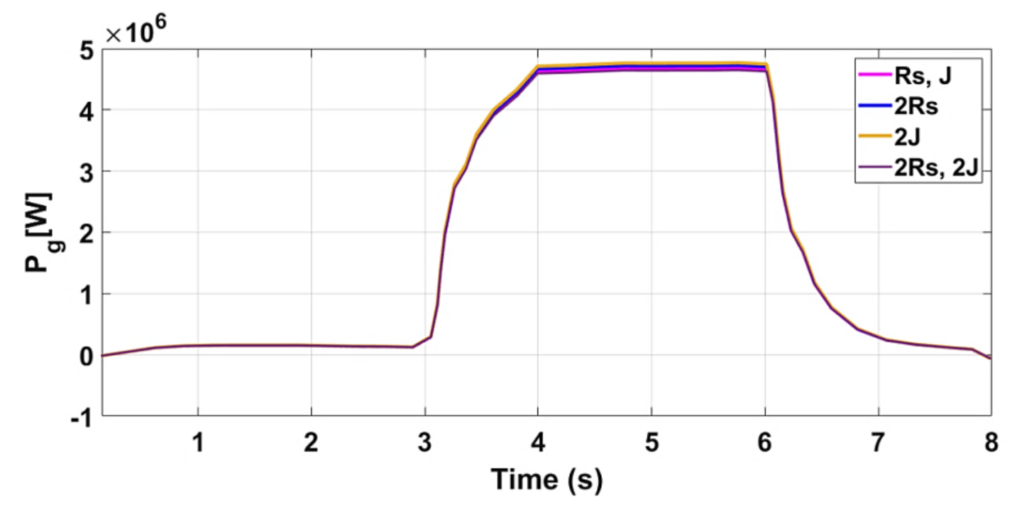
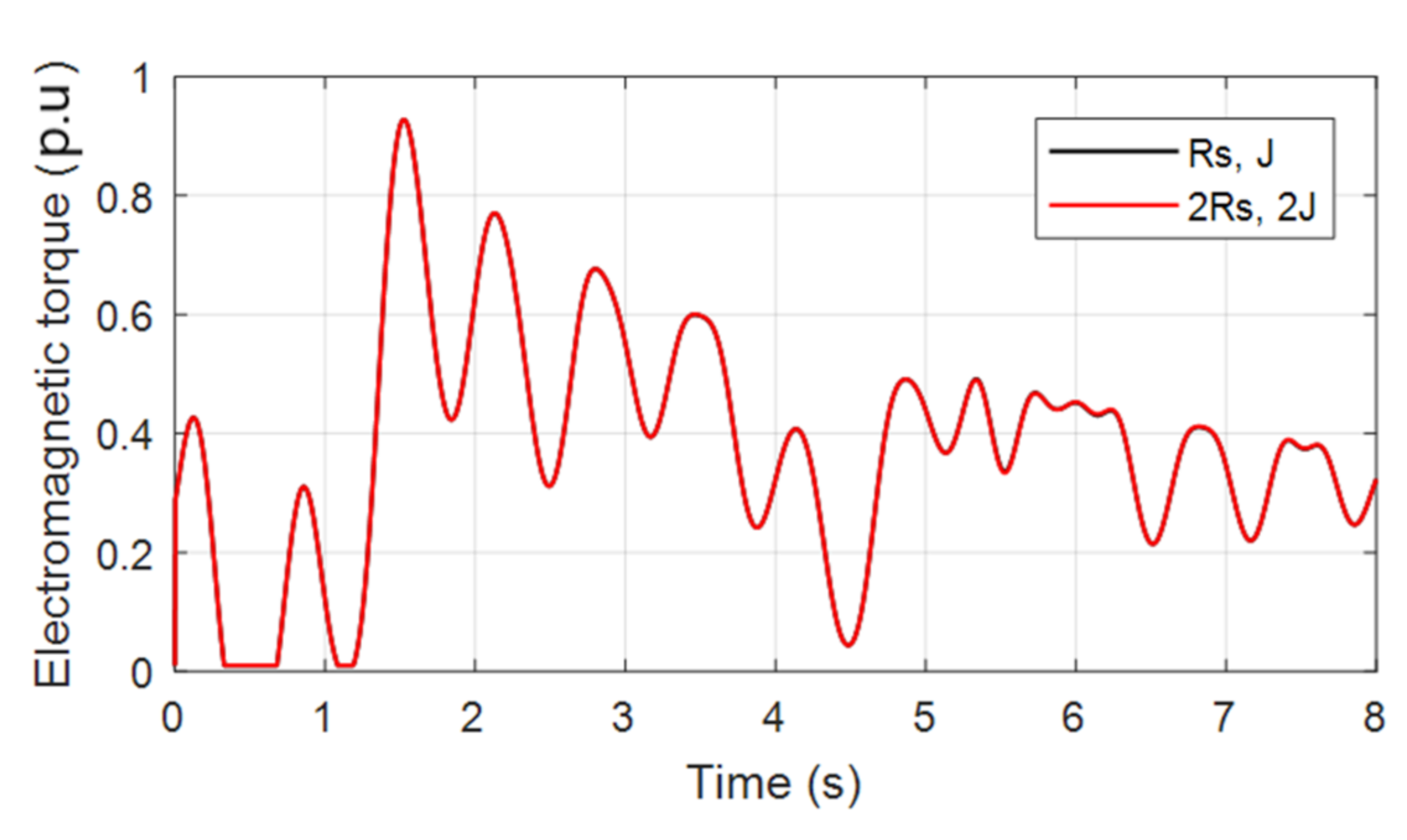
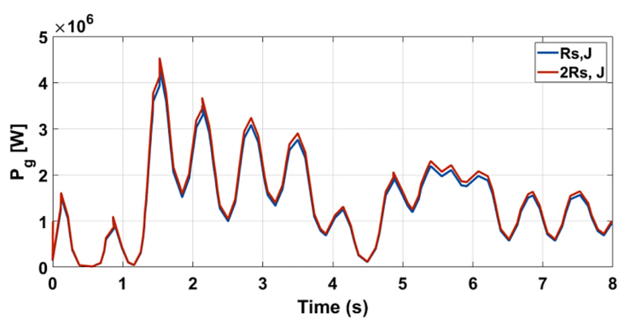
5.2. Robustenss Analysis

In order to test the performance of the system under proposed control, simultaneous variations of +100% in R s and +100% in J were imposed in the simulation model of the system. Figure 14 shows the influence of a simultaneous change of a +100% of the stator resistance R s and +100% of the total inertia J on the dynamics of the DC-link voltage. From the presented results, it is observed that the proposed controller exhibited robustness to such variations and the transient tracking voltage response in the two cases was nearly similar. The measured error in DC-link voltage was approximately ±0.28 for the two cases (see Figure 14). Figure 15 confirms the robustness of the proposed OFSP-HSMC scheme for tracking and regulation of the reactive power to its reference value under the variations. From the presented results, it is observed that the recorded error was ±0.2 × 10⁻⁴ approximately and it was the same as the measured error under fixed parameters. Figure 16 shows the variation of active power under the influence of parameter variations. From the presented results, it is obvious that under parameter variations, the integrated power to the grid was almost the same.

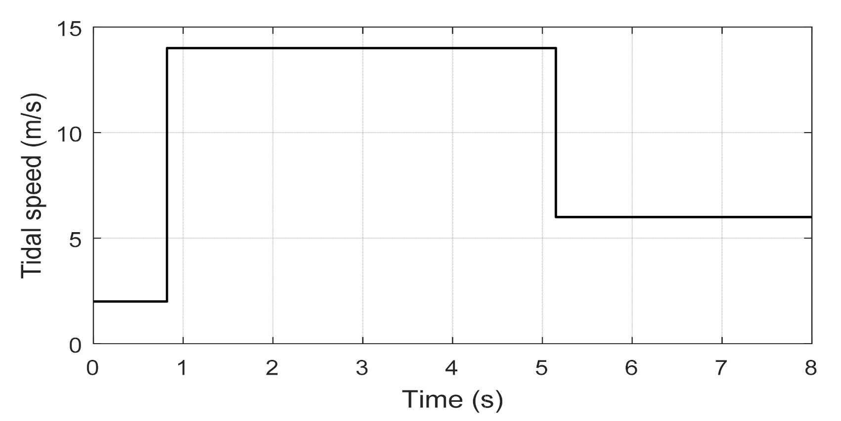
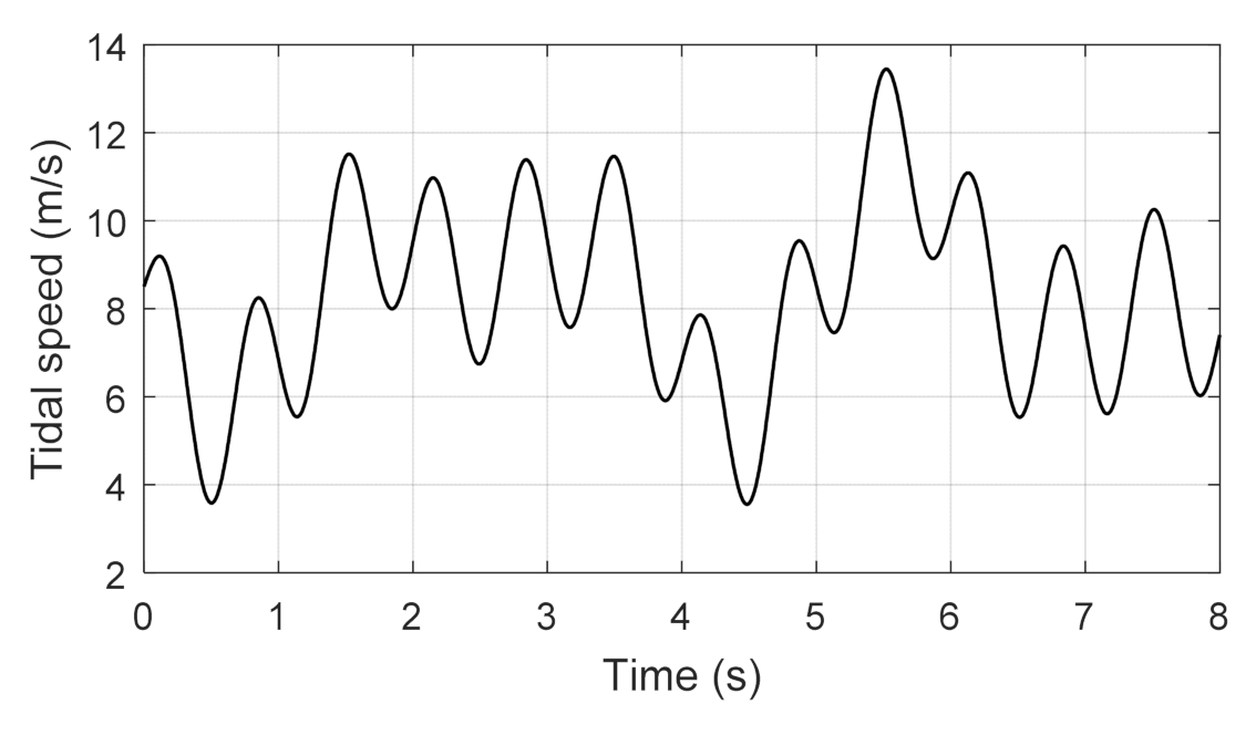
5.3. Test under Random Marine Velocity Profile

In this test, a realistic marine current speed profile was utilized to test the performance of the proposed control system. The speed profile is shown in Figure 17. This marine current profile was selected according to [7,8], where a tidal velocity for a day for a specific location at the Raz de Sein in Bretagne, France has been used. The marine current was random and it had maxima at 13 m/s, while the minimum marine current was 3.8 m/s in the present work.
Figure 18 shows the electromagnetic torque generated using the proposed control scheme. Two simulation results are provided; one with fixed system parameters and the second one were simulated with 100% change in stator resistance and moment of inertia. One can confirm from the presented results that the electromagnetic torque followed almost the same random pattern as the marine current. Most importantly with the proposed controller, the generated electromagnetic torque did not vary much with the parameter changes. The integrated active power to the grid was tested with the proposed control scheme and the results are shown in Figure 19. From the presented results, it is concluded that the proposed controller was robust to parameter changes and the active power also followed a random profile similar to the electromagnetic torque. Moreover, the active power was zero when the marine current speed of Figure 17 fell below 4 m/s, which was a stall condition for the turbine.

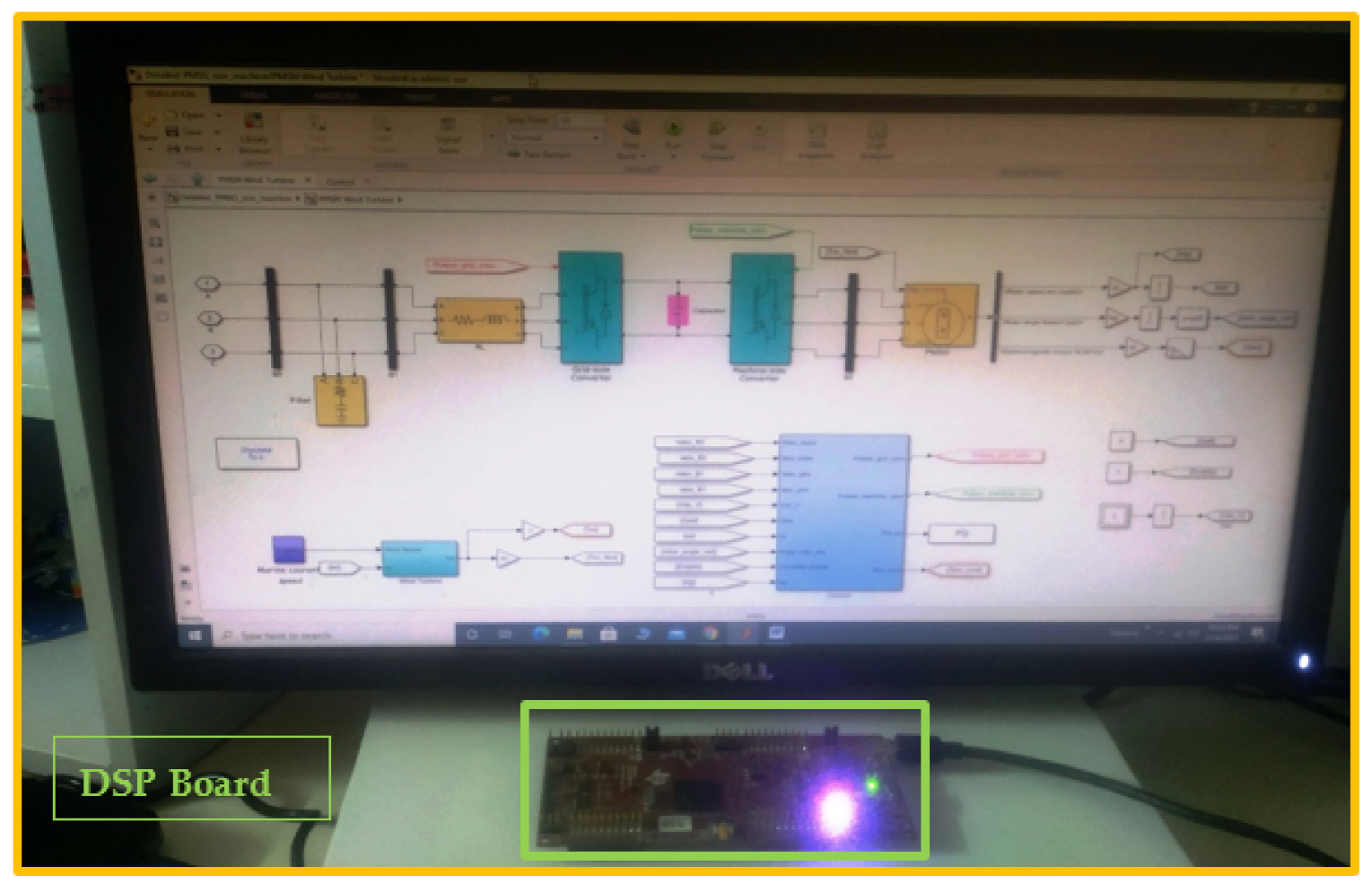
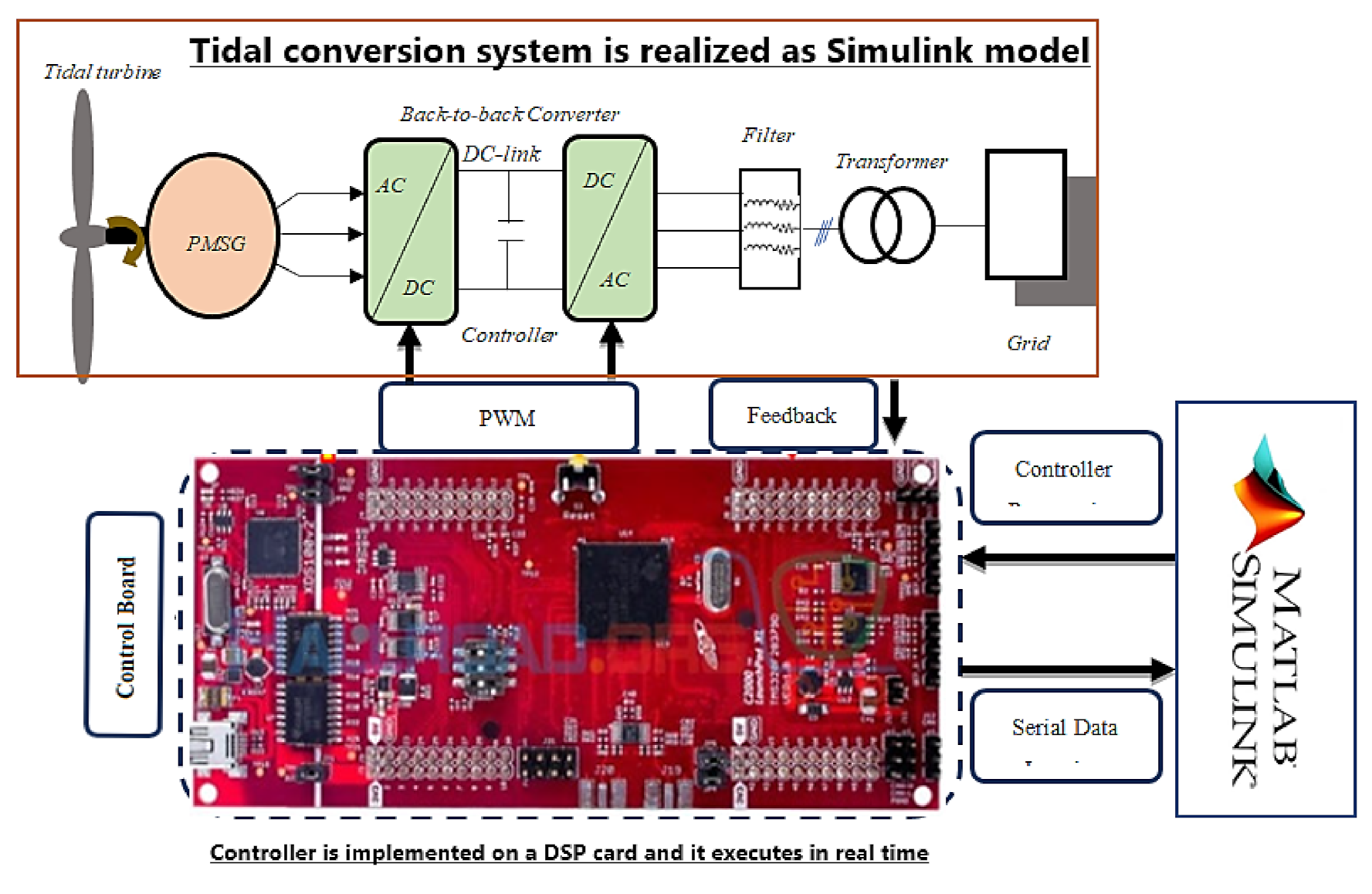
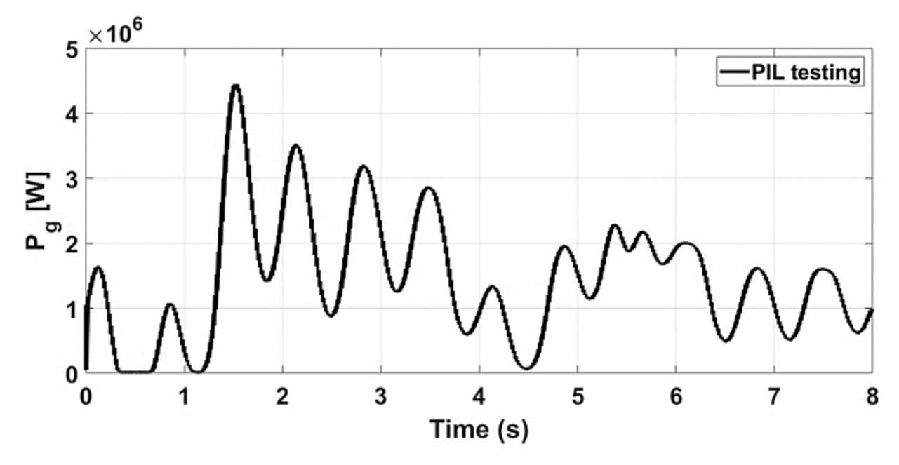
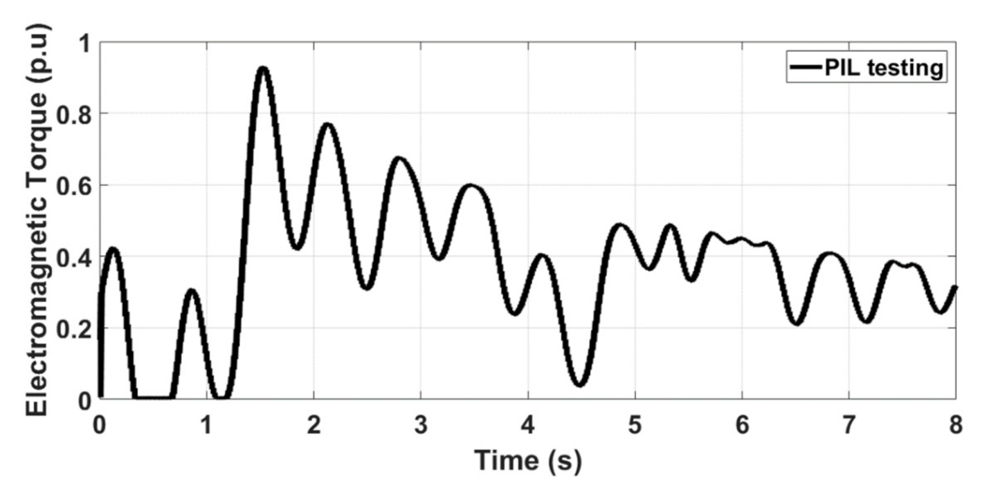
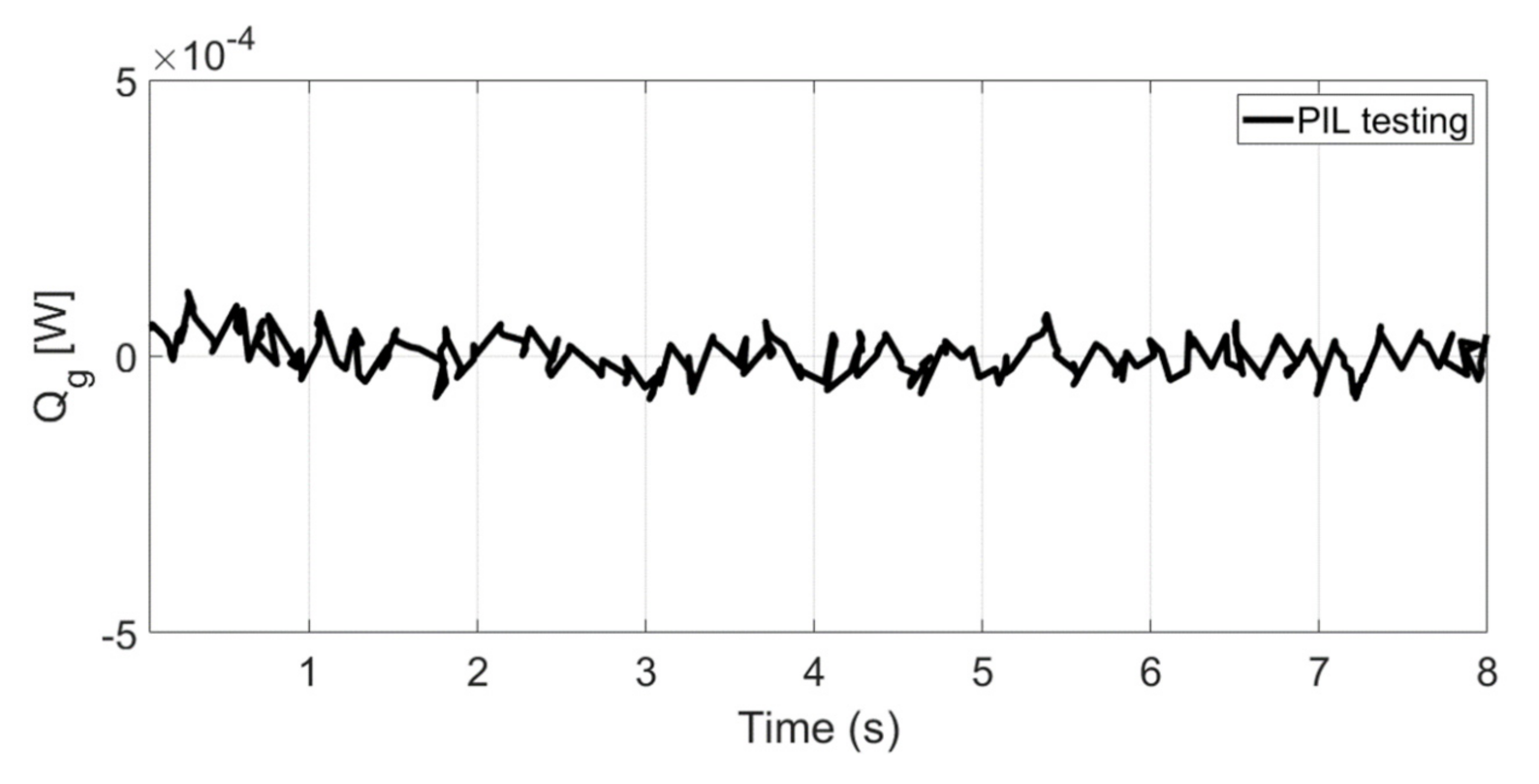
5.4. Processor in the Loop (PIL) Experimental Validation

Processor in the loop experimentation is a powerful tool which is utilized for validating the control system on a hardware processor, while the system plant is a software model. Thus, the control algorithm is tested in real time. More details about processor in the loop experimentation are reported in [42,43,44]. More importantly, the controller validated using PIL testing is equally efficient when it is tested on actual hardware plant [42]. Thus, inspired by the above work, the proposed control schemes were tested using a processor in the loop (PIL) experiment, and the block diagram of the setup is shown in Figure 20 and Figure 21. In the PIL experiment, the DSP control card was physically integrated with the PMSG-based tidal conversion system model running in the Simulink environment. The studied conversion system was developed by using the SimPowerSystems blocks of the MTALAB/Simulink environment. The control schemes were implemented using a discrete time step of 5 × 10⁻⁵ s. The control board consisted of a dual core processor TMS320F379D, which was programmed through the rapid prototyping method from Simulink environment. Discrete versions of the discussed controllers were compiled from Simulink and the output or hex file was programmed into the random access memory (RAM) of the processor. In the PIL experiment, the tidal turbine-based conversion system was not physical, rather it was a Simulink environment, while the controller was working in real time. Data were exchanged between the DSP control card and the software model using a high-speed serial port. Figure 22, Figure 23 and Figure 24 show the experimental results collected using the PIL method for active power, electromagnetic torque and reactive power, respectively. From the presented results, it is very obvious that the active power was similar to the simulated response of Figure 10. Similarly, the electromagnetic torque obtained as a result of PIL testing was also the same as the simulated response of Figure 18. Finally, the PIL testing of reactive power (Figure 24) showed that the reactive power was bounded near zero.

6. Conclusions

A new fuzzy supervisory passivity-based high order sliding-mode controller for a PMSG in a hydro turbine conversion system was proposed. The proposed strategy was adopted to extract the maximum power from the tidal current, taking into account the entire dynamics of the PMSG when synthesizing the controller. A fuzzy gain-PI controller was selected to guarantee the overall rated speed operation of the PMSG and then compute a higher reference torque. Dynamic simulations of the studied system under parameter changes were given special attention and the results have been compared to conventional methods, which show a quick track of the reactive power and the DC-link voltage to their references over the compared controls. All drawbacks of the conversion system were addressed and the objectives were well achieved. The developed control strategy provides the best performance, and higher robustness. Moreover, a PIL test was conducted to prove that the proposed controller is practically implementable. Finally, future works will be focused on the implementation of the proposed work in a real tidal conversion system.

Author Contributions

Conceptualization, Y.B. and N.U.; methodology, M.S.C.; software, Y.B.; validation, Y.B., A.A. and R.N.S.; formal analysis, N.U.; investigation, K.T.; resources, Y.B.; data curation, Y.B.; writing—original draft preparation, Y.B.; writing—review and editing, N.U.; M.S.C.; K.T. visualization, Y.B.; supervision, A.A.; project administration, A.A.; funding acquisition, N.U. and K.T. All authors have read and agreed to the published version of the manuscript.

Funding

This work was supported by Taif University Researchers Supporting Project number (TURSP-2020/144), Taif University, Taif, Saudi Arabia. This research was also supported by grant number ENV6402012N from Prince of Songkla University.

Institutional Review Board Statement

Not applicable.

Informed Consent Statement

Not applicable.

Data Availability Statement

Not applicable.

Conflicts of Interest

The authors declare no conflict of interest.

Appendix A

Proof of the Flux Tracking Error’s Exponential Convergence.
The time derivative along (11) of V e f , yields the following relation:
V ˙ e f = e f T K f e f λ min K f e f 2 , t 0
where λ min K f is the matrix K f represents maximum eigenvalues.
The standard Euclidian norm’s square of e f is expressed as below:
e f 2 = e fd 2 + e fq 2 = e f T e f
Combining (A2) with V e f , yields:
V e f = 0.5 e f T e f e f 2 , t 0
Multiplying both sides of (A3) with ( λ min K f ), yields
λ min K f V e f λ min K f e f 2 , t 0
By combining (A1) with (A4), one obtains the following relation:
V ˙ e f λ min K f V e f , t 0
Integrating both sides of (A9) gives:
V e f V 0 e r f t , t 0
where the term r f = λ min K f 0 . From (A3) at t = 0 , and multiplying it by e r f t , we get:
V 0 e r f t e f 0 2 e r f t
Combining (A6) with (A7) yields:
V e f e f 0 2 e r f t   , t 0
From (A3) and (A8) it gives:
e f t = e f 0 e 0.5 r f t
Therefore, with a rate of convergence r f , the error e f is exponentially decreasing, thus the system is asymptotically stable.

Appendix B

Proof of the Closed-Loop System Stability.
Lemma 1. 
The system is passive only if the dynamics expressed in (15) given by R s 1 d ψ dq * dt + p ω m ψ dq * and ψ dq are considered respectively as input and output.
Proof. 
Multiplying (11) by “ R dq 1 ψ dq T ”, yields:
i dq ψ dq T = 1 2   R dq 1 d dt ψ dq T ψ dq
Given the matrix and since   ψ dq T ψ dq = 0 , the term p ω m R dq 1 ψ dq T ψ dq has no relation with the right hand side of Equation (A10).
Integrating (A10) gives
0 t i dq ψ dq T d τ = 1 2   R dq 1 ψ dq T ψ dq t + 1 2   R dq 1 ψ dq T ψ dq 0
If V f = 1 2 ψ dq T ψ dq is taken as a positive definite function, it yields:
0 t i dq ψ dq T d τ = 1 2   R dq 1 V f t + 1 2   R dq 1 V f 0
Equation (A12) proves the passivity of the system while the energy balance of the system is independent of the term ω m R dq 1 ψ dq T ψ dq , which means that the system is globally stable. □

Appendix C

Proof of the Passivity Propriety of the PMSG Using the E-L Model.
Lemma 3. 
The PMSG dq-mode described by (6)–(8) is said to be passive if X = i dq T ,   ω m T and   Y = v d q T ,   T e T are treated as system inputs and outputs.
Proof. 
Let us define H m , the well-known energy balance Euler–Lagrange systems [41] (the total energy) of the PMSG as follow:
H m = L T q ˙ q ˙ L
where q ˙ is the generalized coordinates and L is the Lagrangian of the PMSG model given as:
L i ˙ dq , ω m = 1 2 i ˙ dq T L dq i ˙ dq + ψ dq T i ˙ dq Electrical Energy + 1 2 J ω m 2 Mechanical Energy
The time derivative of the L i ˙ dq , ω m along the Equations (6)–(8) gives the following relation:
d L i ˙ dq , ω m dt = d i ˙ dq T R i ˙ dq dt + y T ν + d dt ψ dq T i ˙ dq
where R = diag R dq , f fv is the symmetrical definite positive matrix. Integrating both sides of Equation (A15) in the interval [0 T m ] yields:
L T m L 0 Stored Energy = 0 T m i ˙ dq T R i ˙ dq   d τ Dissipated Energy + 0 T m y T ν   d τ + [ ψ dq T i ˙ dq ] 0 T m Supplied Energy
with L T m 0 and L 0 being the initial energy stored. By integrating Equation (A16), a dissipation inequality is deduced, given as:
0 T m y T ν   d τ λ min R 0 T m i ˙ dq 2 d τ ( L 0 + [ ψ dq T i ˙ dq ] 0 T m )
Thus, the relationship M is passive; then, the dynamics of the PMSG are also passive. □

References

  1. Saini, G.; Saini, R.P. A review on technology, configurations, and performance of cross-flow hydrokinetic turbines. Int. J. Energy Res. 2019, 43, 6639–6679. [Google Scholar] [CrossRef]
  2. Benzerdjeb, A.; Abed, B.; Achache, H.; Hamidou, M.K.; Gorlov, A.M. Experimental study on blade pitch angle effect on the performance of a three-bladed vertical-axis Darrieus hydro turbine. Int. J. Energy Res. 2019, 43, 2123–2134. [Google Scholar] [CrossRef]
  3. Zhang, M.; Wang, T.; Tang, T.; Benbouzid, M.; Diallo, D. An imbalance fault detection method based on data normalization and EMD for marine current turbines. ISA Trans. 2017, 68, 302–312. [Google Scholar] [CrossRef] [PubMed]
  4. Mohanty, A.; Viswavandya, M.; Ray, P.K.; Panigrahi, T.K.; Mohanty, S. Stability and optimisation of direct driven permanent magnet synchronous generator based tidal turbine. Vacuum 2019, 166, 341–350. [Google Scholar] [CrossRef]
  5. Othman, A.M. Enhancement of tidal generators by superconducting energy storage and Jaya-based sliding-mode controller. Int. J. Energy Res. 2020, 44, 11658–11675. [Google Scholar] [CrossRef]
  6. Gu, Y.-J.; Yin, X.-X.; Liu, H.-W.; Li, W.; Lin, Y.-G. Fuzzy terminal sliding mode control for extracting maximum marine current energy. Energy 2015, 90, 258–265. [Google Scholar] [CrossRef]
  7. Zhou, Z.; Ben Elghali, S.; Benbouzid, M.; Amirat, Y.; Elbouchikhi, E.; Feld, G. Tidal stream turbine control: An active disturbance rejection control approach. Ocean Eng. 2020, 202, 107190. [Google Scholar] [CrossRef]
  8. Toumi, S.; Elbouchikhi, E.; Amirat, Y.; Benbouzid, M.; Feld, G. Magnet failure-resilient control of a direct-drive tidal turbine. Ocean Eng. 2019, 187, 106207. [Google Scholar] [CrossRef]
  9. Yin, X.; Zhao, X. ADV Preview Based Nonlinear Predictive Control for Maximizing Power Generation of a Tidal Turbine With Hydrostatic Transmission. IEEE Trans. Energy Convers. 2019, 34, 1781–1791. [Google Scholar] [CrossRef]
  10. Gaamouche, R.; Redouane, A.; El Harraki, I.; Belhorma, B.; El Hasnaoui, A. Optimal feedback control of nonlinear variable-speed marine current turbine using a Two-Mass model. J. Marine Sci. Appl. 2020, 19, 83–95. [Google Scholar] [CrossRef]
  11. Moon, S.H.; Park, B.G.; Kim, J.W.; Kim, J.M. Maximum power-point tracking control using perturb and observe algorithm for tidal current generation system. Int. J. Precis. Eng. Manuf. Green Technol. 2020, 7, 849–858. [Google Scholar] [CrossRef]
  12. Sahu, P.C.; Baliarsingh, R.; Prusty, R.C.; Panda, S. Novel DQN Optimized tilt Fuzzy cascade Controller for frequency stability of a tidal energy based AC Microgrid. Int. J. Ambient. Energy 2020. [Google Scholar] [CrossRef]
  13. Chen, H.; Li, Q.; Tang, S.; Aït-Ahmed, N.; Han, J.; Wang, T.; Zhou, Z.; Tang, T.; Benbouzid, M. Adaptive super-twisting control of doubly salient permanent magnet generator for tidal stream turbine. Int. J. Electr. Power Energy Syst. 2021, 128, 106772. [Google Scholar] [CrossRef]
  14. Hu, D.; Teng, Y.; Wu, F. Optimal Control Design of Generator Systems for Marine Current Turbine Applications Using Economic Model Predictive Control. IEEE Access 2020, 8, 208368–208377. [Google Scholar] [CrossRef]
  15. Achour, A.Y.; Mendil, B.; Bacha, S.; Munteanu, I. Passivity-based current controller design for a permanent-magnet synchronous motor. ISA Trans. 2009, 48, 336–346. [Google Scholar] [CrossRef]
  16. Yang, B.; Wu, Q.H.; Jiang, L.; Smith, J.S. Adaptive passivity-based control of a TCSC for the power system damping improvement of a PMSG based offshore wind farm. In Proceedings of the 2013 International Conference on Renewable Energy Research and Applications (ICRERA), Madrid, Spain, 20–23 October 2013; pp. 717–721. [Google Scholar]
  17. Yang, B.; Yu, T.; Shu, H.; Zhang, Y.; Chen, J.; Sang, Y.; Jiang, L. Passivity-based sliding-mode control design for optimal power extraction of a PMSG based variable speed wind turbine. Renew. Energy 2018, 119, 577–589. [Google Scholar] [CrossRef]
  18. Subramaniam, R.; Joo, Y.H. Passivity-Based Fuzzy ISMC for Wind Energy Conversion Systems With PMSG. IEEE Trans. Syst. Man, Cybern. Syst. 2021, 51, 2212–2220. [Google Scholar] [CrossRef]
  19. Yang, B.; Yu, T.; Shu, H.; Qiu, D.; Zhang, Y.; Cao, P.; Jiang, L. Passivity-based linear feedback control of permanent magnetic synchronous generator-based wind energy conversion system: Design and analysis. IET Renew. Power Gener. 2018, 12, 981–991. [Google Scholar] [CrossRef] [Green Version]
  20. Gonzalez, W.G.; Garces, A.; Fosso, A.O.B. Passivity-Based Control for Small Hydro-Power Generation with PMSG and VSC. IEEE Access 2020, 8, 153001–153010. [Google Scholar] [CrossRef]
  21. Belkhier, Y.; Achour, A.Y. Passivity-based voltage controller for tidal energy conversion system with permanent magnet synchronous generator. Int. J. Control Autom. Syst. 2020, 19, 1–11. [Google Scholar] [CrossRef]
  22. David, F.M.; Ortega, R. Adaptive passivity-based control for maximum power extraction of stand-alone windmill systems. Control Eng. Pract. 2012, 20, 173–181. [Google Scholar] [CrossRef]
  23. Cisneros, R.; Mancilla-David, F.; Ortega, R. Passivity-Based Control of a Grid-Connected Small-Scale Windmill with Limited Control Authority. IEEE J. Emerg. Sel. Top. Power Electron. 2013, 1, 247–259. [Google Scholar] [CrossRef]
  24. Hosseinzadeh, M.; Yazdanpanah, M.J. Robust adaptive passivity-based control of open-loop unstable affine non-linear systems subject to actuator saturation. IET Control Theory Appl. 2017, 11, 2731–2742. [Google Scholar] [CrossRef]
  25. López-García, I.; Beltran-Carbajal, F.; Espinosa-Pérez, G.; Escarela-Perez, R. Passivity-based power control of a doubly fed induction generator with unknown parameters. Int. Trans. Electr. Energy Syst. 2016, 26, 2402–2424. [Google Scholar] [CrossRef]
  26. López-García, I.; Espinosa-Perez, G.; Siguerdidjane, H.; Dòria-Cerezo, A. On the passivity-based power control of a doubly-fed induction machine. Int. J. Electr. Power Energy Syst. 2013, 45, 303–312. [Google Scholar] [CrossRef]
  27. Dong, J.; Li, S.; Wu, S.; He, T.; Yang, B.; Shu, H.; Yu, J. Nonlinear Observer-Based Robust Passive Control of Doubly-Fed Induction Generators for Power System Stability Enhancement via Energy Reshaping. Energies 2017, 10, 1082. [Google Scholar] [CrossRef]
  28. Gu, Y.; Li, W.; He, X. Passivity-Based Control of DC Microgrid for Self-Disciplined Stabilization. IEEE Trans. Power Syst. 2015, 30, 2623–2632. [Google Scholar] [CrossRef]
  29. Cornejo, C.; Icaza, L.A. Passivity based control of a seismically excited building. In Proceedings of the 16th IFAC World Congress, Prague, Czech Republic, 4–8 July 2005. [Google Scholar]
  30. Zakeri, H.; Antsakli, P.J. Recent advances in analysis and design of cyber-physical systems using passivity indices. In Proceedings of the 27th Mediterranean Conference on Control and Automation (MED), Akko, Israel, 1–4 July 2019; pp. 31–36. [Google Scholar]
  31. Benmouna, A.; Becherif, M.; Depernet, D.; Ebrahim, M.A. Novel Energy Management Technique for Hybrid Electric Vehicle via Interconnection and Damping Assignment Passivity Based Control. Renew. Energy 2018, 119, 116–128. [Google Scholar] [CrossRef]
  32. Belkhier, Y.; Achour, A.Y. Fuzzy passivity-based linear feedback current controller approach for PMSG-based tidal turbine. Ocean Eng. 2020, 218, 108156. [Google Scholar] [CrossRef]
  33. Nicklasson, P.J.; Ortega, R.; Espinosa-Pérez, G. Passivity-based control of the general rotating electrical machine. In Proceedings of the 33rd IEEE Conference on Decision and Control, Lake Buena Vista, FL, USA, 14–16 December 2002; pp. 4018–4023. [Google Scholar] [CrossRef]
  34. Lu, E.; Li, W.; Yang, X.; Liu, Y. Anti-disturbance speed control of low-speed high-torque PMSM based on second-order non-singular terminal sliding mode load observer. ISA Trans. 2019, 88, 142–152. [Google Scholar] [CrossRef]
  35. Lee, M.A.; Takagi, H. Dynamic control of genetic algorithms using fuzzy logic techniques. In Proceedings of the International conference on Genetic Algorithms, San Mateo, CA, USA, 17–22 July 1993; pp. 76–83. [Google Scholar]
  36. Yubazaki, N.; Otani, M.; Ashida, T.; Hirota, K. Dynamic fuzzy control method and its application to positioning of induction motor. In Proceedings of the 4th IEEE International Conference on Fuzzy Systems, Yokohama, Japan, 20–24 March 1995; pp. 1095–1102. [Google Scholar]
  37. Mamdani, E.H.; Assilian, S. Fuzzy sets for man-machine interaction. Int. J. Man Mach. Stud. 1999, 8, 687–697. [Google Scholar]
  38. Mousa, H.H.H.; Youssef, A.-R.; Mohamed, E.E.M. Variable step size P&O MPPT algorithm for optimal power extraction of multi-phase PMSG based wind generation system. Int. J. Electr. Power Energy Syst. 2019, 108, 218–231. [Google Scholar] [CrossRef]
  39. Diallo, M.O.F.; Youssef, S.; Gualous, H.; Camara, M.B.; Dakyo, B. Permanent magnet synchronous generator for tidal turbine application in Raz Blanchard—Modeling and control strategy. In Proceedings of the 2014 16th International Power Electronics and Motion Control Conference and Exposition, Antalya, Turkey, 21–24 September 2014; pp. 377–381. [Google Scholar] [CrossRef]
  40. Priya, G.J. Modelling and performance analysis of grid connected PMSG based wind turbine. Int. J. Adv. Res. Electr. Electron. Instrum. Eng. 2014, 3, 155–165. [Google Scholar]
  41. Touimi, K.; Benbouzid, M.; Tavner, P. Tidal stream turbines: With or without a Gearbox? Ocean Eng. 2018, 170, 74–88. [Google Scholar] [CrossRef]
  42. Ullah, N.; Farooq, Z.; Sami, I.; Chowdhury, S.M.; Techato, K.; Alkhammash, H.I. Industrial Grade Adaptive Control Scheme for a Micro-Grid Integrated Dual Active Bridge Driven Battery Storage System. IEEE Access 2020, 8, 210435–210451. [Google Scholar] [CrossRef]
  43. Ullah, N.; Sami, I.; Chowdhury, S.M.; Techato, K.; Alkhammash, H.I. Artificial Intelligence Integrated Fractional Order Control of Doubly Fed Induction Generator-Based Wind Energy System. IEEE Access 2021, 9, 5734–5748. [Google Scholar] [CrossRef]
  44. Ullah, N.; Ullah, A.; Ibeas, A.; Herrera, J. Improving the Hardware Complexity by Exploiting the Reduced Dynamics-Based Fractional Order Systems. IEEE Access 2017, 5, 7714–7723. [Google Scholar] [CrossRef]
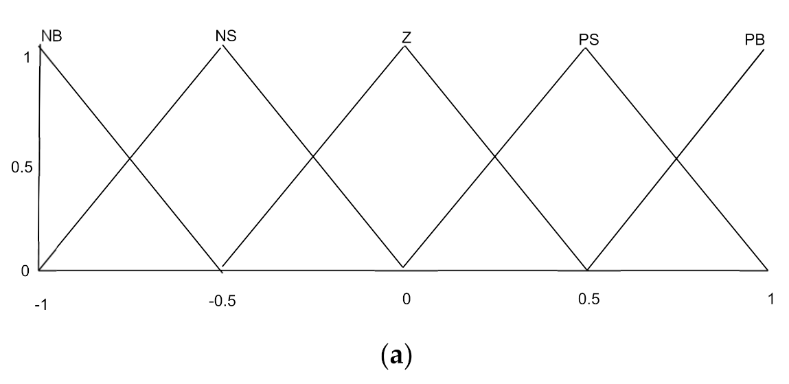
Figure 1. Tidal conversion system under Simulink.
Actuators 10 00092 g001
Figure 2. Proposed strategy design.
Actuators 10 00092 g002
Figure 3. Fuzzy gain supervisory high order sliding-mode controller (HSMC) design.
Actuators 10 00092 g003
Figure 4. The fuzzy controller configuration: (a) inputs ε m function and (b) outputs ε m function.
Actuators 10 00092 g004aActuators 10 00092 g004b
Figure 5. Fuzzy gain supervisory PI design.
Actuators 10 00092 g005
Figure 6. Grid-side converter (GSC) PI controller schemas.
Actuators 10 00092 g006
Figure 7. Tidal speed.
Actuators 10 00092 g007
Figure 8. DC-link voltages.
Actuators 10 00092 g008
Figure 9. Zoom on DC-link voltages.
Actuators 10 00092 g009
Figure 10. Reactive power.
Actuators 10 00092 g010
Figure 11. Zoom on reactive power.
Actuators 10 00092 g011
Figure 12. Generated voltages.
Actuators 10 00092 g012
Figure 13. Generated active powers.
Actuators 10 00092 g013
Figure 14. DC-link with parameter changes.
Actuators 10 00092 g014
Figure 15. Reactive powers with parameter changes.
Actuators 10 00092 g015
Figure 16. Active power with parameter changes.
Actuators 10 00092 g016
Figure 17. Random marine current speed.
Actuators 10 00092 g017
Figure 18. Electromagnetic torque.
Actuators 10 00092 g018
Figure 19. Active power.
Actuators 10 00092 g019
Figure 20. Experimental DSP board.
Actuators 10 00092 g020
Figure 21. Experimental step.
Actuators 10 00092 g021
Figure 22. Active power.
Actuators 10 00092 g022
Figure 23. Electromagnetic torque.
Actuators 10 00092 g023
Figure 24. Reactive power.
Actuators 10 00092 g024
Table 1. Fuzzy logic rules.
ε ω / ε dq NBNSZPSPB
ε ω / ε dq
NBNBNBNSNSZ
NSNBNBNSZPS
ZNSNSZPSPS
PSNSZPSPBPB
PBZPSPSPBPB
Table 2. System parameters.
PMSG ParameterValue
Water density ( ρ )1024 kg/m2
Stator resistance ( R s )0.006 Ω
Tidal turbine radius ( R )10 m
Stator inductance ( L dq )0.3 mH
Pole pairs number ( p )48
Flux linkage ( ψ f )1.48 Wb
Total inertia ( J )35,000 kg.m2
DC-link capacitor (C)2.9 F
Grid voltage ( V g )574 V
DC-link voltage ( V dc )1150 V
Grid-filter resistance ( R f )0.3 pu
Grid-filter inductance ( L f )0.3 pu
Publisher’s Note: MDPI stays neutral with regard to jurisdictional claims in published maps and institutional affiliations.

