Article

Angle Magnetization Rotation Method for Characterizing Co-Rich Amorphous Ferromagnetic Microwires

1
National University of Science and Technology “MISiS” (NUST “MISiS”), Leninskiy Prospekt 4, Moscow 119049, Russia
2
Pushkov Institute of Terrestrial Magnetism, Ionosphere and Radio Wave Propagation (IZMIRAN), Kaluzhskoe sh. 4, Troitsk, Moscow 108840, Russia
3
Financial University under the Government of the Russian Federation (FU), Leningradsky pr. 49, Moscow 125993, Russia
*
Author to whom correspondence should be addressed.
Submission received: 22 March 2021 / Revised: 14 April 2021 / Accepted: 27 April 2021 / Published: 29 April 2021
(This article belongs to the Special Issue Recent Advances in Magnetic Sensors and Actuators)

Abstract

:
A low-frequency model of the magnetization reversal of a microwire is developed for those cases when the microwire magnetization response can go beyond the linear approximation. The analysis of the influence of external magnetic fields on the process of magnetization reversal of the microwire, including the hysteresis mode, was performed. The characteristic dependences of the amplitude of the electromotive force, U2f, arising in the pick-up coil wound around the microwire are obtained. It was established that, in the region of relatively small-acting circular and longitudinal magnetic fields, the U2f signal could have a region with the opposite sign. An extended small-angle magnetization rotation method was used to verify the proposed model and test glass-coated, amorphous, Co-rich microwires. During the experiments, the amplitude of the second harmonic, U2f, arising in the pick-up coil when an alternating electric current with the frequency f flows through the microwire, was measured as a function of the applied longitudinal magnetic field at various mechanical tensile stresses. The effective anisotropy field, the magnetostriction constant, and the residual quenching stress of the investigated microwires were determined by comparing the theoretical and experimental data.

1. Introduction

The glass-coated amorphous ferromagnetic microwires obtained by means of the Taylor-Ulitovsky method possess a unique combination of both magnetic and mechanical properties [1,2]. This well-developed method allows producing microwires with different compositions for a wide range of the metal core diameters, d = 0.5–30 μm and the total diameters, D = 10–40 μm. The microwires with a different d/D ratio, compositions, and amorphous/crystalline state are promising for various technological applications in magnetic sensors and actuators.
Glass-coated Heusler-type (Ni-Mn-Ga composition) microwires exhibiting martensitic transformation can show a magnetic shape memory effect and a magnetocaloric effect [3,4] The Fe-rich microwires with a high magnetostriction constant can exhibit mechanical rotation under the excitation of axial alternating magnetic fields at suitable conditions [5,6]. This rotational effect has been applied when a load is fixed to the end of the wire [7].
The Co-rich microwires show a giant magnetoimpedance (GMI) effect that can be used to develop highly sensitive sensors of a weak external magnetic field [8,9,10,11,12]. Such microwires are characterized by a small negative magnetostriction constant (λs ~ −(1−3) × 10−7), a linear hysteretic loop with a very low value of the coercive force, Hc ~ 0.05 Oe, and a small effective anisotropy field, Ha, 1–5 Oe.
The character of the hysteresis loop of glass-coated microwires is widely believed to be closely related to the magnetostriction constant sign and value [1,2,13,14]. Moreover, the magnetic anisotropy and the domain structure of amorphous microwires are affected by the preparation parameters because the Taylor-Ulitovsky method involves fast quenching from the melt of the metallic nuclei surrounded by glass coating [2,14]. Therefore, large internal stresses linked to the difference in thermal expansion coefficients of glass-coating and metallic nucleus are induced in the process fabrication [14,15]. Consequently, accurate measurements of the basic magnetic parameters of amorphous ferromagnetic microwires are essential for a better understanding of their magnetic characteristics and for applications in various devices, e.g., magnetic or stress sensors [16,17,18]. Among these properties, the saturation magnetostriction constant and the amplitude of residual quenching stresses are the principal parameters.
Indirect evaluation of the magnetostriction constant of amorphous magnetic materials can be performed by analyzing the stress dependence of magnetic susceptibility in ribbons [19] and microwires [20]. For the same purposes, the small-angle magnetization rotation (SAMR) method was used in ribbons [21,22,23]. Initially, this method was developed only to characterize magnetic materials in which the magnetization rotation was the main re-magnetization mechanism [19]. The first attempts to evaluate the magnetostriction constant of glass-coated microwires were used in Co-rich microwires presenting linear hysteresis loops typical for the magnetization rotation process [24,25]. In References [26,27], the SAMR method has been successfully used to measure the magnetostriction constants with negative and positive signs of various amorphous glass-coated ferromagnetic microwires.
Nevertheless, the full potential of the SAMR method for microwires can be revealed only if the magnetic anisotropy of the microwires is taken into account. The magnetic anisotropy is associated with the distribution of the residual quenching stresses over the metallic nucleus of a microwire. In Reference [28], a new modified version of the SAMR method was successfully applied for Co-rich microwires. Within this method, an analytical expression and experimental data show the amplitude of the second harmonic value of the electro motive force occurring in the pick-up coil when a weak ac current flows through the microwire is obtained as a function of applied external magnetic field, H > Ha (Ha is an effective anisotropy field) at different mechanical tensile stresses. Comparing the experimental and theoretical data, the effective anisotropy field Ha, the magnetostriction constant λs, and the amplitude of the residual quenching stress ∆σ weredetermined for a family of Co-rich, glass-coated microwires.
In this work, we proposed a low-frequency model of the microwire magnetization reversal and substantiated the extension of the small-angle magnetization rotation method for the case when the response of the microwire magnetization goes beyond the linear approximation. Nonlinear response of the microwire is observed under the action of weak longitudinal magnetic fields, H ≤ Ha, and also when the amplitude of a circular magnetic field, Hφ, generated by the alternating current If flowing through the microwire is comparable to the effective anisotropy field of the microwire, HφHa. To emphasize this feature, the method proposed in this work is called the angle magnetization rotation method (AMR). This method was used to study glass-coated, amorphous, Co-rich microwires and makes it easy to determine the effective anisotropy field of a microwire and its magnetostriction constant along with the internal quenching stress.

2. Numerical Simulation

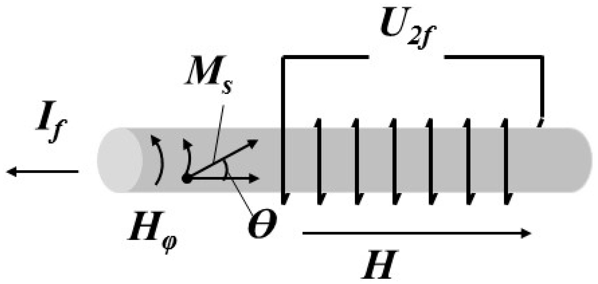
2.1. Model Description

Here, we consider the magnetization behavior of a glass-coated, amorphous, Co-rich microwire as a function of the applied alternating circular and direct longitudinal magnetic fields. We assume that the microwire has an ideal cylindrical shape and is characterized by saturation magnetization Ms in the course of our calculations. The microwire has a small, negative, magnetostriction constant λs < 0, and the quenching stresses ∆σ = (σzz − σφφ) inside the microwire are evenly distributed throughout the volume. At each point of the microwire, the magnetization M(r) reaches its saturation Ms and can change only its direction. Besides, we assume that the radius rc of the exchange core is significantly smaller than the radius of the metal core r0 (rc << r0), and its effect on the microwire magnetization reversal process can be neglected.
Let us consider an amorphous microwire of length L with a metal core radius r0 << L. Let a pick-up coil of length l < L be wound on a given microwire containing N turns. Figure 1 shows the configuration of a microwire with a pick-up coil in a direct, longitudinal, uniform magnetic field. An exciting alternating current If flows through the microwire with the frequency f = ω/2π and creates a circular field Hφ (r,t) inside the microwire at an arbitrary point of radius r:
H φ ( r , t ) = r r 0 H a c cos ω t = 2 I 0 c r 0 2 cos ω t ,
where Hac is the amplitude of the exciting field on the surface of the wire where r = r0. The frequency of the exciting alternating current is low (f = 5–10 kHz), and the amplitude of the exciting current If can be arbitrary. The sought-for value is the amplitude of the EMF signal at the frequency of the second harmonic U2f arising in the pick-up coil in an external, longitudinal, uniform magnetic field.
Under the assumptions made, the magnetic energy of a microwire can be written in the following form:
W ( θ , h , h φ ) = M s H a w = M s H a ( 1 2 cos 2 θ h cos θ h φ sin θ ) ,
where w is the dimensionless magnetic energy, Ms is the saturation magnetization of the microwire metal core, Ha is the microwire effective anisotropy field, H a = 3 | λ s | ( σ z z σ φ φ ) / M s ( σ i j are the residual stress tensor components), h = H/Ha is the dimensionless longitudinal magnetic field, hφ = Hφ/Ha is the dimensionless circular field created by the current flowing through the microwire, θ is the angle between the magnetization vector and the microwire axis, the value α = Mz/Ms = cosθ is the longitudinal dimensionless component of the magnetization, and, at the same time, the dimensionless density of the longitudinal magnetic flux. Note that the magnetic energy does not depend on the angle φ, since the magnitude of the azimuthal field Hφ (1) at any point under consideration does not depend on it. At the same time, the effective anisotropy field Ha is the only dimensional parameter of the model that determines the characteristic values of the external field components.
Under the influence of external magnetic fields, the direction of the magnetization vector is adjusted in such a way as to provide a minimum of the local magnetic energy given by Equation (2) at each point of the microwire. From the condition W / θ = 0 , one obtains the equilibrium curves that provide the relationship between the equilibrium direction of magnetization and the components of the external field θ = θ ( h , h φ ( r , t ) ) at each point of the microwire. The value of the dimensionless average longitudinal magnetic flux at each moment of time t is given by the formula below.
cos θ ¯ = α ¯ ( h , h φ ( r 0 , t ) , σ ) = 1 π r 0 2 S α ( h , h φ ( r 0 , t ) , σ ) d s ,
where S is the cross-sectional area of the microwire metal core. The specified magnetic flux is expanded in a Fourier series at frequencies that are multiples of the frequency of the exciting field: α ¯ ( t ) = a 0 2 + n = 1 ( a n cos ( n ω t ) + b n sin ( n ω t ) ) . Its change induces an EMF in the pick-up coil:
V ( t ) = π r 0 2 μ 0 N M s ω n = 1 n ( b n cos ( n ω t ) a n sin ( n ω t ) ) ,
Since the response is determined at the doubled frequency of the exciting signal in the small-angle magnetization rotation method, we consider only the second coefficients a2 and b2 (n = 2) of expansion (4) and their dependence on the longitudinal field h and the exciting circular field hφ.

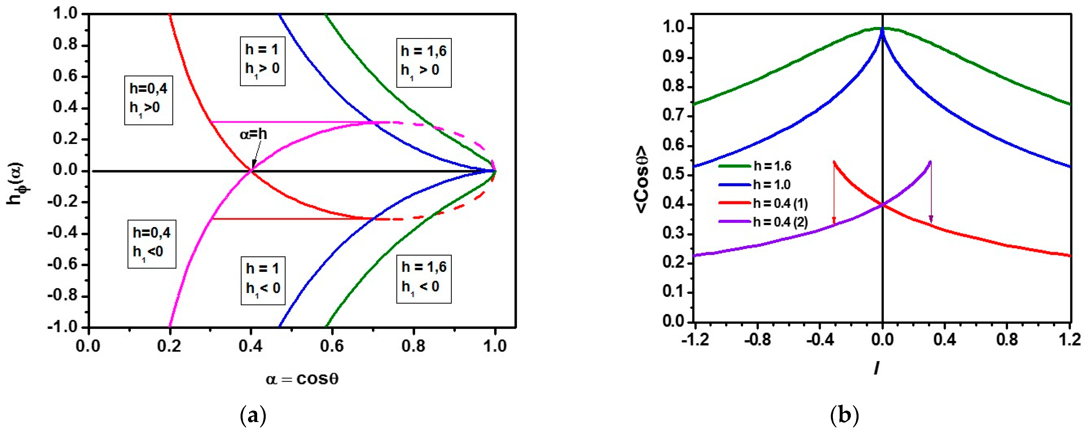
2.2. Equilibrium Magnetization Curves

Let us rewrite the dimensionless energy in Equation (2) using a variable α = cosθ and find two equilibrium curves:
w = 1 2 α 2 h α h φ 1 α 2 ; w / α = 0 h φ ( α , h ) = ± h 1 ; h 1 = h α α 1 α 2
The upper sign in dimensionless energy w corresponds to the case when sin θ ≥ 0 and the lower one correspond to the case when sin θ ≤ 0. In the case of small longitudinal fields, h < 1.0, the minimum of the function h1 is reached at the point αm = h1/3 and it is equal to h1(αm) = −(1 − h2/3)3/2Figure 2a shows the curves of the hφ(α) equilibrium at three different values of the dimensionless longitudinal magnetic field: h = 0.4, 1.0, and 1.6. In the small longitudinal fields, the branches corresponding to different signs in Equation (5) coexist in the range of values of the circular field ( 1 h 2 / 3 ) 3 / 2 h φ ( 1 h 2 / 3 ) 3 / 2 . They form a loop in the region of longitudinal magnetization α1 < α < 1, but only the range α1 < α < αm = h1/3, where each point of the branch corresponding to a steady state has a physical meaning. The left edge of the loop α1 is determined by the equality –h1(αm) = h1(α1). The two mentioned branches, which together form a loop, are depicted in red and lilac colors in Figure 2a.
With a decrease in the circular field from larger values, the equilibrium state of magnetization moves along the red curve, where sin θ ≥ 0. In the fields h φ < ( 1 h 2 / 3 ) 3 / 2 , a second stable state hφ = −h1 appears in the system (lilac curve), which, at hφ > 0, has a relatively high energy. When hφ < 0, the state on the red curve becomes less favorable, since it has more energy than that of on the lilac curve. Finally, the state with sin θ ≥ 0 (red curve) loses stability when passing through the value h φ = h 1 ( α m ) = ( 1 h 2 / 3 ) 3 / 2 , and the system jumps from the red curve to the lilac one. Figure 2a shows this jump as a thin, red, horizontal line. This jump corresponds to a downward jump of the longitudinal magnetization. A further decrease in hφ leads to a smooth decrease of α. With a reverse change in the transverse field, the reverse jump of the magnetization from the lilac branch to the red one occurs at h φ = h 1 ( α m ) = ( 1 h 2 / 3 ) 3 / 2 . We believe that the transition between the branches occurs simultaneously in the entire volume of the wire, as soon as it happens on the surface of the wire.
Hysteresis disappears at h > 1 and the states with the magnetization of sin θ > 0 and sin θ < 0 at hφ = 0 smoothly transform into each other. Both branches of the dependence (5) are shown in Figure 2a in blue (h = 1) and green (h = 1.6), respectively.
To obtain quantitative values of the second harmonic amplitude of the microwire response, U2f, it is necessary to calculate the average magnetic flux (3) over the microwire section. Since dependencies (5) connect α and hφ at any point of the microwire, that is, α = α ( r ) , h φ ( r ) = h φ ( r 0 ) r / r 0 , and the longitudinal field is uniform throughout the microwire, the integral (3) can be reduced to the form ( α 0 = α ( r 0 ) ).
α ¯ = { 2 h 1 2 ( h h 3 6 + h 2 α 0 2 α 0 3 3 h ln ( h α 0 ) + h 2 α 0 ) , α 0 α m , h 1 2 h 1 2 ( h 2 h 2 + 1 3 + h 2 α 0 2 α 0 3 3 h ln ( h α 0 ) + h 2 α 0 ) , α 0 1 , h > 1 ,
It can be shown that α ¯ α 0 > 0 always holds. It is possible to obtain a dependence α ¯ ( h φ ( r 0 ) ) from Equations (5) and (6), which, in essence, corresponds to the average, dimensionless, magnetic flux as a function of the dimensionless exciting current I~hac = Hac/Ha. The corresponding plots are shown in Figure 2b for the same values of dimensionless longitudinal fields as in Figure 2a.

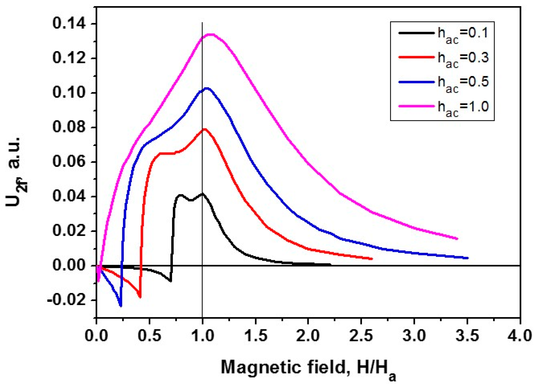
2.3. Calculation of the Second Harmonic Amplitude

It follows from Figure 2a,b that the excitation of a microwire by an alternating current in a longitudinal field h < 1 can lead to the appearance of jumps in the magnetization at transitions between the equilibrium curves.
The behavior of the microwire magnetization depends on the amplitude of an exciting alternating current If. The behavior of the Fourier coefficient a2(h) at different values of the amplitude If corresponding to the dimensionless circular field on the surface of the microwire hac = 0.1, 0.3, 0.5, and 1.0 is shown in Figure 3. As can be seen in the plots presented, the larger the amplitudes of If oscillations are, the lower the longitudinal field h is required for the hysteresis regime to appear in the region of small, longitudinal, magnetic fields H < Ha. It is important to note that the range of magnetization oscillations increases with an increase in the longitudinal magnetic field at h < 1, and the time dependence becomes more symmetric, α(t) → α(−t) (see Equation (1)). With a further increase in the longitudinal field h > 1, the change in magnetization during oscillations of the exciting field decreases again. As a result, the response of the system is maximal at h ≈ 1. With an increase in the amplitude of the exciting field ha, the contribution of the effects due to the amplitude decreasing to the coefficient a2 manifests itself later, and the maximum of the response shifts toward higher longitudinal fields. In the region of relatively low longitudinal fields, where the magnetization reversal of the wire proceeds without transitions between the magnetization reversal curves, the output signal has a different sign. Its maximum is observed at ha ≈ 0.5. All the features listed above qualitatively follow from the analysis of the magnetization curves.
It is worth noting that the response also contains the second coefficient b2 in the hysteresis mode of magnetization reversal, and the value of b2 is largely determined by the magnitude of the magnetization jump between the modes, which has a maximum at an intermediate value of the longitudinal field 0 < h < 1. The strength of the longitudinal field at which the hysteresis mode of magnetization reversal depends on the magnitude of the circular field.

3. Materials and Methods

To check the dependences obtained within our model, we performed studies of glass-coated Co-rich microwires manufactured by the Taylor-Ulitovsky method. Segments of microwires with the composition Co69Fe4Cr4Si12B11, an outer radius R = 14.25 µm, a metal core radius r0 = 6.75 µm, and a length of L = 100 mm were used as samples [29,30,31]. The ends of the microwire samples were pre-stripped from the glass shell to ensure electrical contact with a special holder.
The magnetic hysteresis curves were determined by an inductive method at different applied tensile stresses. The measurement system had a differential pick-up coil with an inner diameter of 0.5 mm/20 mm in length and a magnetization solenoid of a 4 mm diameter/70 mm length. The solenoid driven by a saw-toothed 200 Hz frequency current, which produced a magnetic field with an amplitude of 10 Oe. The voltage signal generated by the pick-up coil was digitally integrated to obtain the hysteresis curves.
The angle magnetization rotation measurements were performed in a wide range of magnetic fields ±10 Oe. The second EMF harmonic measurements (10 kHz) were carried out for the excited ac current at frequency f = 5 kHz. The number of the pick-up coil turns were N = 630. The amplitude of the second EMF harmonic U2f(H) is measured as a function of the external magnetic field applied along the axis of the microwire at different applied tensile stresses. Small mechanical loads m of 0.3 g, 2.3 g, and 4.3 g attached to the free end of a vertically suspended microwire produced the applied tensile stress [23]. In our case, the mechanical loads produced applied tensile stresses, σapp, of 9.4 MPa, 72 MPa, and 134 MPa, respectively.

4. Results and Discussion

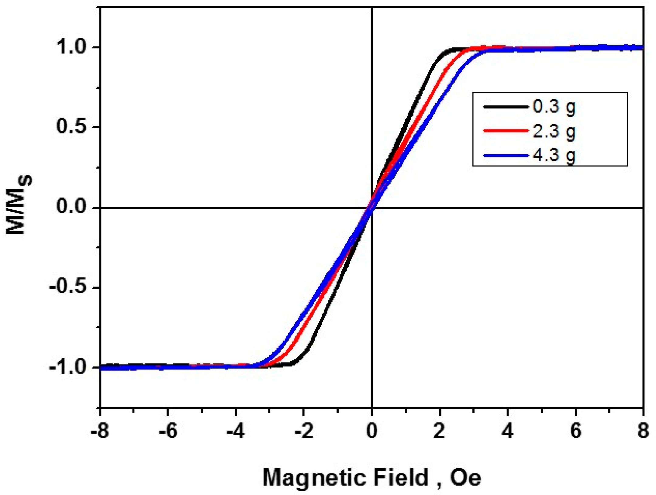
4.1. Magnetization Curves

Initially, the hysteresis loops of the investigated microwires were measured. The microwire hysteresis loops at different values of the applied tensile stresses are shown in Figure 4. In the initial state (black curve), the microwire is characterized by a small anisotropy field Ha ~ 1.9 Oe and a quasilinear section in the region fields −Ha < H < +Ha with a coercive force of no more than 0.05 Oe. When additional mechanical loads were applied (2.3 g—red curve and 4.3 g—blue curve), the slope of the loop is decreased and the value of Ha is increased.

4.2. Measurements by the AMR Method

During the measurements by the AMR method (angular rotation of the magnetization vector), the curves of the EMF signal dependence on the second harmonic of the external magnetic field U2f(H) were obtained at various tensile stresses. The AMR curves in the entire range ±Hmax of magnetic fields are centrally symmetric. Therefore, only the parts of the curves measured in the region of positive external magnetic fields from zero to Hmax >> Ha are presented and discussed below.
The AMR curves obtained at different amplitudes from 1 mA to 6 mA of the exciting alternating current without applied tensile stresses are displayed in Figure 5. Following from Figure 3, the effective anisotropy field of the microwire coincides very well with the maximum of the AMR curve at the values of hφ ≤ 0.5. In our case, the AMR curve measured at an excitation current amplitude of 2 mA corresponds to such a criterion since the amplitude of the circular field generated on the surface of the microwire is Hφ = 0.6 Oe, and the effective anisotropy field corresponding to the maximum of this curve is Ha = 1.8 Oe (hφ = Hφ/Ha = 0.3).
In general, the behavior of the experimental curves in Figure 5 is in good agreement with the calculated data in Figure 3. In particular, the behavior of the curves depends on the amplitude of the exciting alternating current as predicted by our model. It is clearly seen that, at the low current amplitudes of 1 mA (hφ = 0.15) and 2 mA (hφ = 0.3), the sections with the opposite sign of the slope are observed in the region of low longitudinal fields (H < Ha). These features weaken at 3 mA (hφ = 0.5) and disappear at an alternating current amplitude of 6 mA where hφ = 1. In the region of longitudinal fields H ~ Ha (h = 1), all curves have a maximum, and, at H > Ha (the regime of small-angle magnetization rotations), rapidly decrease to zero values.
The AMR curves obtained for the alternating current amplitude of 2 mA (hφ = 0.3) and under the influence of small tensile mechanical stresses are shown in Figure 6. In weak longitudinal magnetic fields (H < Ha), all curves have an increasing nonlinear section, reach a maximum in the region of fields H > Ha, and fall to zero with increasing longitudinal magnetic fields H > Ha. When mechanical loads are applied, the maximum of the AMR curve, corresponding to the effective anisotropy field, shifts to the region of higher magnetic field values (see Figure 6). That is, the magnitude of the effective anisotropy field Ha.i corresponding to a specific tensile stress σapp.i can be determined from the position of the maximum of the corresponding curve. This is an important circumstance, since the known values of Ha.i can be used to determine the value of the internal quenching stresses ∆σ of the microwire from the system of linear equations [28].
Ha.i = H0σ + σapp.i)/σ0,
where H0 is the nominal anisotropy field and σ0 = 100 MPa is the characteristic amplitude of the residual quenching stresses. In our case, the values of the effective anisotropy fields were 1.8 Oe, 2.2 Oe, and 2.6 Oe with the application of tensile stresses of 9.4 MPa (load 0.3 g), 72 MPa (load 2.3 g), and 134 MPa (load 4.3 g), respectively. The value of internal quenching stresses was estimated as ∆σ = 272 MPa.
The value of the magnetostriction constant λs is determined on the falling parts of the measured AMR curves in the region of longitudinal magnetic H > Ha [28]. A certain fixed value of the EMF of the second harmonic U2f1 is selected, for which the H–σapp diagram is constructed and the ratio ∆H/σapp is determined. From these data, the magnetostriction constant, λs = −1.1 × 10⁻⁷, can be obtained from the following expression [23].
λ s = 1 3 M s Δ H Δ σ a p p
To increase the accuracy, such calculations can be repeated for different values of the second harmonic EMF amplitude, U2fn.

5. Conclusions

In this work, a model of the low-frequency angular rotation of the magnetization vector in amorphous ferromagnetic microwires in the entire region of acting circular and longitudinal magnetic fields is proposed. This model allows making a visual analysis of the influence of the microwire parameters and the acting fields on the process of its magnetization reversal including the hysteresis mode.
It is shown that the characteristic dependences of the amplitude of the EMF signals U2f arising in the pick-up coil are in good agreement with the experimental data. It was established that the EMF signal U2f has the opposite sign in the region of relatively low longitudinal fields (H < Ha). For the case of small amplitudes of the exciting current, the maximum EMF signal U2f is achieved at the value of the longitudinal field, which is equal in magnitude to the effective anisotropy field of the microwire H = Ha.
The proposed model substantiates the extension of the small-angle magnetization rotation method. Further development of the model allows taking into account the off-diagonal components of the microwire stress tensor.

Author Contributions

Conceptualization, S.G., Y.G. and B.L.; methodology, B.L.; software, Y.G.; validation, S.G. and B.L.; formal analysis B.L.; investigation, A.P. and Y.G.; resources, V.T. and E.G.; data curation, S.G. and E.G.; writing—original draft preparation, S.G. and A.P.; visualization, A.P.; supervision, V.T.; project administration, E.G.; funding acquisition, V.T. All authors have read and agreed to the published version of the manuscript.

Funding

This research was funded by the Russian Science Foundation, grant number 20-19-00607.

Institutional Review Board Statement

Not applicable.

Informed Consent Statement

Not applicable.

Data Availability Statement

Please contact with Sergey Gudoshnikov ([email protected]).

Conflicts of Interest

The authors declare no conflict of interest.

References

  1. Phan, M.H.; Peng, H.X. Giant magnetoimpedance materials: Fundamentals and applications. Prog. Mater. Sci. 2008, 53, 323–420. [Google Scholar] [CrossRef]
  2. Zhukov, A.; Zhukova, V. Magnetic Properties and Applications of Ferromagnetic Mircowires with Amorphous and Nanocrystalline Structure; Nova Science Publishers, Inc.: New York, NY, USA, 2009. [Google Scholar]
  3. Zhukov, A.; Ipatov, M.; del Val, J.J.; Zhukova, V.; Chernenko, V.A. Magnetic and structural properties of glass-coated Heusler-type microwires exhibiting martensitic transformation. Sci. Rep. 2018, 8, 621. [Google Scholar] [CrossRef] [Green Version]
  4. Garcia, C.; Zhukova, V.; Shevyrtalov, S.; Ipatov, M.; Corte-Leon, P.; Zhukov, A. Tuning of magnetic properties in Ni-Mn-Ga Heusler-type glass -coated microwires by annealing. J. Alloys Compd. 2020, 838, 155481. [Google Scholar] [CrossRef]
  5. Chiriac, H.; Marinescu, C.S.; Ovári, T.-A. Large gyromagnetic effect in magnetostrictive amorphous wires. Sens. Actuators A 2000, 81, 126–128. [Google Scholar] [CrossRef]
  6. Lunaa, C.; Raposo, V.; Garshelis, I.; Zhukov, A.P.; Iñiguez, J.I.; Vázquez, M. Inducing rotation and levitation in magnetostrictive wires and rods: Correlated amplitude and frequency of exciting ac axial magnetic field. Sens. Actuators 2003, 106, 274–277. [Google Scholar] [CrossRef]
  7. Sugino, T.; Takezawa, M.; Honda, T.; Yamasaki, J. Basic load characteristics of magnetostrictive amorphous wire micro-motor. IEEE Trans. Magn. 2001, 37, 2871–2873. [Google Scholar] [CrossRef]
  8. Panina, L.V.; Mohri, K. Magneto-impedance effect in amorphous wires. Appl. Phys. Lett. 1994, 65, 1189. [Google Scholar] [CrossRef]
  9. Beach, R.; Berkowitz, A. Giant magnetic field dependent impedance of amorphous FeCoSiB wire. Appl. Phys. Lett. 1994, 64, 3652–3654. [Google Scholar] [CrossRef]
  10. Knobel, M.; Vázquez, M.; Kraus, L. Giant magnetoimpedance. In Handbook of Magnetic Materials; Buschow, K.H.J., Ed.; Elsevier: Amsterdam, The Netherlands, 2003; Volume 15, pp. 497–563. [Google Scholar]
  11. Zhukov, A.; Ipatov, M.; Zhukova, V. Advances in Giant Magnetoimpedance of Materials. In Handbook of Magnetic Materials; Buschow, K.H.J., Ed.; Elsevier: Amsterdam, The Netherlands, 2015; Volume 24, pp. 139–236. [Google Scholar] [CrossRef]
  12. Ipatov, M.; Zhukova, V.; Zhukov, A.; Gonzalez, J. Magnetoimpedance sensitive to dc bias current in amorphous microwires. Appl. Phys. Lett. 2010, 97, 252507. [Google Scholar] [CrossRef]
  13. Kabanov Yu Zhukov, A.; Zhukova, V.; Gonzalez, J. Magnetic domain structure of wires studied by using the magneto-optical indicator film method. Appl. Phys. Lett. 2005, 87, 142507. [Google Scholar] [CrossRef]
  14. Chiriac, H.; Ovari, T.A. Amorphous glass-covered magnetic wires: Preparation, properties, applications. Prog. Mater Sci. 1996, 40, 333–407. [Google Scholar] [CrossRef]
  15. Antonov, A.S.; Borisov, V.T.; Borisov, O.V.; Prokoshin, A.F.; Usov, N.A. Residual quenching stresses in glass-coated amorphous ferromagnetic microwires. J. Phys. D Appl. Phys. 2000, 33, 1161. [Google Scholar] [CrossRef]
  16. Gudoshnikov, S.; Usov, N.; Nozdrin, A.; Ipatov, M.; Zhukov, A.; Zhukova, V. Highly sensitive magnetometer based on the off-diagonal GMI effect in Co-rich glass-coated microwire. Phys. Status Solidi A 2014, 211, 980–985. [Google Scholar] [CrossRef]
  17. Herrero-Gómez, C.; Aragón, A.M.; Hernando-Rydings, M.; Marín, P.; Hernando, A. Stress and field contactless sensor based on the scattering of electromagnetic waves by a single ferromagnetic microwire. Appl. Phys. Lett. 2014, 105, 092405. [Google Scholar] [CrossRef] [Green Version]
  18. Herrero-Gómez, C.; Marín, P.; Hernando, A. Bias free magnetomechanical coupling on magnetic microwires for sensing applications. Appl. Phys. Lett. 2013, 103, 142414. [Google Scholar] [CrossRef] [Green Version]
  19. Vazquez, M.; Fernengel, W.; Kronmüller, H. The effect of tensile stresses on the magnetic properties of Co58Fe5Ni10Si11B16 amorphous alloys. Phys. Status Solidi 1983, 80, 195–204. [Google Scholar] [CrossRef]
  20. Gonzalez, J.; Zhukov, A.P.; Blanco, J.M.; Cobeno, A.F.; Vazquez, M.; Kulakowski, K. Evaluation of the saturation magnetostriction in nearly zero magnetostrictive glass-coated amorphous microwires. J. Appl. Phys. 2000, 87, 5950. [Google Scholar] [CrossRef]
  21. Narita, K.; Yamasaki, J.; Fukunaga, H. Measurement of saturation magnetostriction of a thin amorphous ribbon by means of small-angle magnetization rotation. IEEE Trans. Magn. 1980, 16, 435–439. [Google Scholar] [CrossRef]
  22. Hernando, A.; Vazquez, M.; Madurga, V.; Kronmuller, H. Modification of the saturation magnetostriction constant after thermal treatments for the Co58Fe5Ni10B16Si11 amorphous ribbon. J. Magn. Magn. Mater. 1983, 37, 161–166. [Google Scholar] [CrossRef]
  23. Hernando, A.; Vazquez, M.; Madurga, V.; Ascasibar, E.; Liniers, M. Influence of the anisotropy on the “SAMR” method for measuring magnetostriction in amorphous ribbons. J. Magn. Magn. Mater. 1986, 61, 39–47. [Google Scholar] [CrossRef]
  24. Zhukova, V.; Blanco, J.M.; Zhukov, A.; Gonzalez, J. Studies of the magnetostriction of as-prepared and annealed glass-coated Co-rich amorphous microwires by SAMR method. J. Phys. D Appl. Phys. 2001, 34, L113. [Google Scholar] [CrossRef]
  25. Zhukova, V.; Blanco, J.M.; Zhukov, A.; Gonzalez, J.; Torcunov, A.; Larin, V. Magnetostriction of glass-coated Co-rich amorphous microwires and its dependence on current annealing. J. Magn. Magn. Mater. 2003, 254–255, 94–96. [Google Scholar] [CrossRef]
  26. Churyukanova, M.; Semenkova, V.; Kaloshkin, S.; Shuvaeva, E.; Gudoshnikov, S.; Zhukova, V.; Shchetinin, I.; Zhukov, A. Magnetostriction investigation of soft magnetic microwires. Phys. Status Solidi A 2015, 213, 363–367. [Google Scholar] [CrossRef]
  27. Zhukov, A.; Churyukanova, M.; Kaloshkin, S.; Sudarchikova, V.; Gudoshnikov, S.; Ipatov, M.; Talaat, A.; Blanco, J.M.; Zhukova, V. Magnetostriction of Co–Fe-based amorphous soft magnetic microwires. J. Electron. Mater. 2016, 45, 226–234. [Google Scholar] [CrossRef]
  28. Gudoshnikov, S.; Churyukanova, M.; Kaloshkin, S.; Zhukov, A.; Zhukova, V.; Usov, N.A. Investigation of the properties of Co-rich amorphous ferromagnetic microwires by means of small angle magnetization rotation method. J. Magn. Magn. Mater. 2015, 387, 53–57. [Google Scholar] [CrossRef]
  29. Popova, A.V.; Odintsov, V.I.; Menshov, S.A.; Kostitsyna, E.V.; Tarasov, V.P.; Zhukova, V.; Zhukov, A.; Gudoshnikov, S.A. Continuous control of a resistance in Corich amorphous ferromagnetic microwires during DC Joule heating. Intermetallics 2018, 99, 39–43. [Google Scholar] [CrossRef]
  30. Gudoshnikov, S.; Odintsov, V.; Liubimov, B.Y.; Menshov, S.; Popova, A.; Tarasov, V. Correlation of electrical and magnetic properties of Co-rich amorphous ferromagnetic microwires after DC Joule heating treatment. J. Alloys Compd. 2020, 845, 156220. [Google Scholar] [CrossRef]
  31. Kozlov, I.V.; Elmanov, G.N.; Prikhodko, K.E.; Kutuzov, L.V.; Tarasov, B.A.; Mikhalchik, V.V.; Svetogorov, R.D.; Mashera, V.S.; Gorelikov, E.S.; Gudoshnikov, S.A. The evolution of structure and magnetoimpedance characteristics of amorphous Co69Fe4Cr4Si12B11 microwires under heat treatment. J. Magn. Magn. Mater. 2020, 493, 165681. [Google Scholar] [CrossRef]
Figure 1. Schematic configuration of a microwire with a pick-up coil, external applied magnetic fields, microwire magnetization, and measured response.
Actuators 10 00093 g001
Figure 2. Set of equilibrium curves calculated for three values of the dimensionless longitudinal magnetic field: h = 0.4 (red/purple curves), h = 1.0 (blue curves), and h = 1.6 (green curves). (a) Local curves of equilibrium hφ(α). (b) The dependence of the average magnetic flux on the dimensionless exciting current applied to the microwire.
Actuators 10 00093 g002
Figure 3. Fourier coefficient a2 as a function of the dimensionless, longitudinal, magnetic field h, for the cases when Hac/Ha = hac = 0.1, 0.3, 0.5, and 1.0.
Actuators 10 00093 g003
Figure 4. Hysteresis loops of the microwire in the initial state (0.3 g) and under additional mechanical load of 2.3 g and 4.3 g.
Actuators 10 00093 g004
Figure 5. AMR curves for the alternating current amplitudes of 1 mA, 2 mA, 3 mA, and 6 mA.
Actuators 10 00093 g005
Figure 6. AMR curves at the driving current of 2 mA and various mechanical loads.
Actuators 10 00093 g006
Publisher’s Note: MDPI stays neutral with regard to jurisdictional claims in published maps and institutional affiliations.

