
Design and Modeling of a Bio-Inspired Flexible Joint Actuator

School of Mechanical Engineering, Hangzhou Dianzi University, Hangzhou 310018, China
*
Author to whom correspondence should be addressed.
Actuators 2021, 10(5), 95; https://0-doi-org.brum.beds.ac.uk/10.3390/act10050095
Submission received: 1 April 2021
/
Revised: 19 April 2021
/
Accepted: 28 April 2021
/
Published: 30 April 2021
Abstract
:Spiders rely on a hydraulic system to stretch their legs but use muscles to make their legs flex. The compound drive of hydraulics and muscle makes an integrate dexterous structure with powerful locomotion abilities, which perfectly meets the primary requirements of advanced robots. Inspired by this hydraulics-muscle co-drive joint, a novel flexible joint actuator was proposed and its driving characteristics were preliminarily explored. The bio-inspired flexible joint manifested as a double-constrained balloon actuator, which was fabricated by the composite process of 3D printing and casting. To evaluate its performance, the mathematical model was deduced, as well as the finite element analysis (FEA) model. A series of experiments on the rotation angles, driving forces, and efficiencies of the flexible joint were carried out and compared with the mathematical calculations and FEA simulations. The results show that the accuracy of the two theoretical models can be used to assess the joint actuator. The locomotion test of a soft arthropod robot with two flexible joints was also implemented, where the moving speed reached 22 mm/s and the feasibility of the proposed flexible joint applied to a soft robot was demonstrated.
1. Introduction
Most of the traditional robots are composed of rigid components which can perform tasks quickly, accurately, and repeatedly. However, they have some intrinsic shortcomings such as a complex structure, limited flexibility, and poor safety and adaptability [1,2]. Compared with the rigid robot, the body of the soft robot is made of elastic soft materials. In the case of collision or extrusion with the external environment, the body of the soft robot can realize continuous deformation, effectively avoiding or reducing the damage from the outside, thus having a greater advantage in human–robot interactions and other applications [3,4,5]. Soft robots also have stronger adaptability to the environment, which has gradually become a research hotspot in recent years [6,7,8]. The design of soft robots is generally derived from biomimetics [9,10,11]. Some researchers have designed different types of flexible actuators inspired by the structure of natural organisms, and a pneumatic driving mode is more popular because of its advantages of simple mode, low cost, and strong pressure resistance. Wehner et al. designed a bio-inspired Octopus robot by using the gas generated from the catalytic reaction of hydrogen peroxide solution as the pressure source [12]. Manfredi et al. proposed a soft pneumatic inchworm robot for colonoscopies [13]. Cianchetti et al. presented a new novel actuator based on electroactive polymers (EAPs) technology for bio-inspired robotics [14].
As a large group, there are about 1.1 million known species of arthropods, accounting for about 85% of the total animal species [15]. Due to the differentiation and diversity of their soft bodies, they have a considerable degree of adaptability and can exist in almost any space on the earth. The arthropods generally have tough exoskeletons (composed of chitin and protein) and flexible joints. This structure characteristic enables them to show a higher strength to weight ratio than cephalopods, which provides a new direction for the development of soft robots. As one of the most typical arthropods, arachnids use hydraulic systems to stretch their legs [16,17], combining their dexterous structure with powerful locomotion abilities, which perfectly satisfies the major needs of modern robots. Some researchers have preliminarily investigated the bionic design of spiders’ hydraulic joints. Zentner et al. linearized the hydraulic joint into an elastic spring damping system and claimed that the research on spiders’ hydraulic joint may promote the design and manufacture of microdevices [18]. Menon et al. proposed a hydrostatic-driven flexible joint composed of a hose and two adjacent rigid bodies. The hose was inflated by injecting pressure oil, thus driving the two rigid bodies to produce an angular displacement [19]. However, the hose and the rigid bodies were independent of each other, which increased the complexity of the device. Besides, it was necessary to assemble several such joint modules to produce a large displacement due to the small angular displacement. Liu et al. analyzed the hydraulic principle of a spider leg and constructed a bio-inspired joint by using a hydraulic piston-cylinder [20]. However, the response and drive efficiency may not be high due to the large frictional resistance caused by the piston movement.
Although the driving mechanism of the spider’s hydraulic leg has been clear, there are few related bionic designs, and there is a big gap with the dexterous structure and strong movement ability of the spider’s biological prototype. A novel bio-inspired flexible joint is proposed in this paper. The balloon joint is similar to the corrugated folding structure of the spider’s leg joint membrane, with a simple principle and high execution efficiency, and it is placed in the protection of two exoskeletons made of resin material. The proposed bio-inspired flexible joint overcomes the shortcomings of some bionic designs imitating a spider’s hydraulic leg by simplifying the joint structure and enhancing the exoskeleton protection, which is expected to realize the combination of dexterous structure and powerful drive capability.
2. Bio-Inspired Flexible Joint
2.1. Double-Constrained Balloon Actuator
The spider locomotion depends on the drive motion of the knee joint and tibial posterior tarsal joint (collectively referred to as hydraulic joints) [11]. There are only flexors at these two hydraulic joints, but no extensors. The hydraulic joint extension is generally driven by the pressure of hemolymph in the body, as shown in Figure 1a–c, while the joint flexion relies heavily on the flexors. Inspired by the co-drive method of hydraulics and muscle, a novel flexible joint is proposed, manifested as a double-constrained balloon actuator and two adjacent hollow exoskeletons shown in Figure 1d–f. The extension of the spider leg is caused by the increase of the hemolymph pressure in the hydraulic joint. Likewise, the pneumatic (or hydraulic) elastic actuator is placed between the two tough exoskeletons to realize joint extension by inflation pressure. The joint flexion is basically achieved by the recovery of the elastic actuator itself and the “flexor” spring set between the two exoskeletons. In this paper, the double-constrained balloon actuator is emphasized without considering the flexor spring.
The spider’s locomotion is mainly implemented by the hydraulic joint with flexible corrugated folding. When the hemolymph pressure in the leg increases, the joint membrane expands, thus driving the joint to stretch. Its working principle is similar to that of the fluid elastic actuator. Due to the advantages of being lightweight, wide sourced, and pollution-free, a new type of double-constrained balloon elastic actuator is proposed. As shown in Figure 2, its structure is a fan-shaped configuration with two connected chambers, and the thickness of insider layer is smaller than other layers. When the gas pressure in the actuator increases, the expanding volume of the insider layer is larger because of the thin thickness, and then the two constrained chambers expand and squeeze each other, thus making the fan-shaped driver rotate. Of course, the thinner the thickness of the inside layer, the larger the rotation of the joint, but the pressure bearing capacity of the joint will be reduced. The center of rotation is similar to that of the hydraulic joint.
2.2. Soft Arthropod Robot with Two Joints
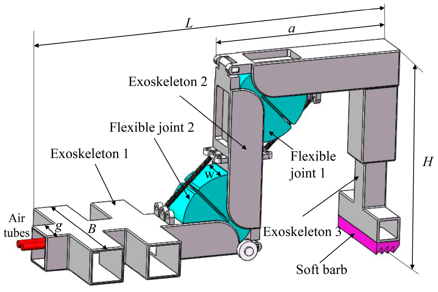
The structure of the eight-legged spider is complicated, as well as its control strategy. It is very difficult to carry out a completely bionic design imitating its physiological characteristics. Single-leg mode is a promising breach to study the soft arthropod robot since the motion of the spider leg is mainly driven by the knee joint and the tibial posterior tarsal joint (two hydraulic joints). As shown in Figure 3, a soft arthropod robot was constructed with two proposed flexible joints.
As shown in Figure 3, the single-legged soft arthropod robot was mainly composed of two flexible joints, three-section exoskeletons, and a soft barb. Exoskeleton 1 plays a role in supporting the ground firmly and preventing the robot from a rollover in the process of movement. The other two exoskeletons act as limb segments and protect the two flexible joints. To improve the locomotion ability of the robot, a soft barbed mechanism was designed, which was made of silica gel and had a serrated contact surface to increase the friction with the ground. The specific parameters of the soft arthropod robot are shown in Table 1, where d3 is the side layer thickness of the flexible joint, w1 is the thickness of the balloon chamber, w1 = w − 2 × d3. The other parameters have been illustrated in Figure 2 and Figure 3.
2.3. Fabrication of Flexible Joint
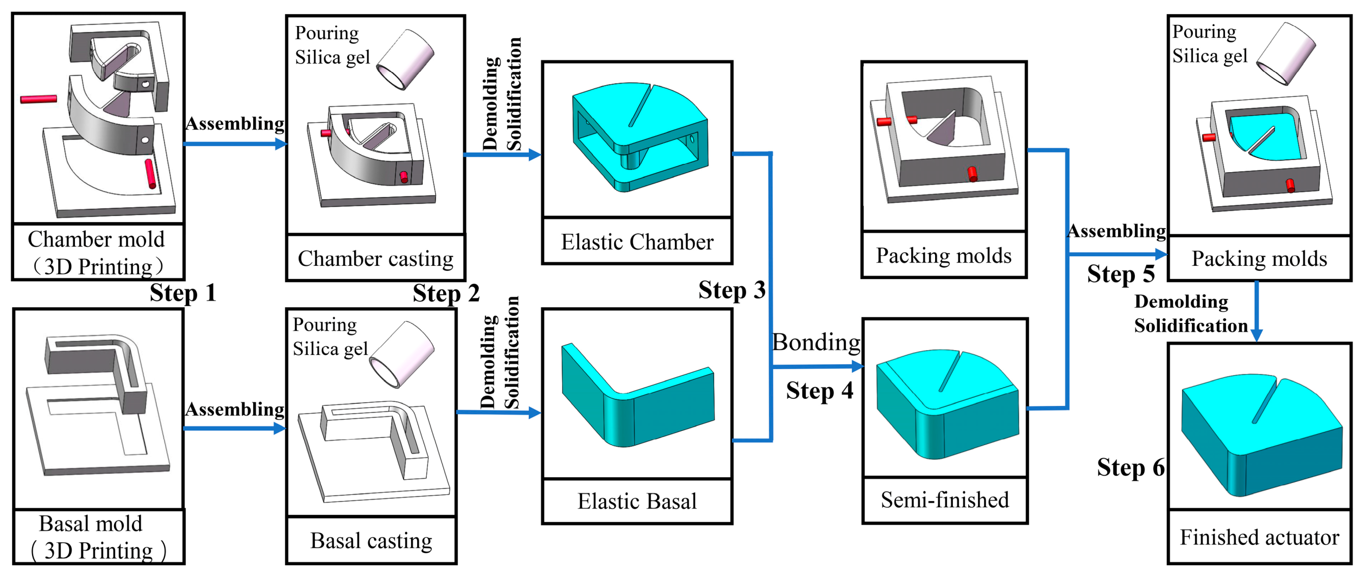
Since the double-constrained balloon elastic actuator is irregular and small, it is hard to utilize 3D printing for one-step formation. The specific fabrication steps are illustrated in Figure 4.
- Step 1: 3D printing molds. The pneumatic actuator can be divided into two parts, the chamber and the basal, all of them are made of casting. A stereolithography 3D printer EP-A650A Pro made by SHINNING 3D Co. Ltd. (Zhejiang, China) was used to make the chamber mold and basal mold. After printing, the molds were polished with 220 mesh to 5000 mesh sandpaper.
- Step 2: Preparing silica gel solution and casting. The silica gel solution (RTV-2) and curing agent (TEOS) were mixed in a container according to the weight ratio of 100:2, and the mixture was evenly stirred by an electromagnetic mixer. The prepared silicone gel solution was put into a vacuum tank, a negative pressure of—98 kpa was applied and left to stand for 5 min for defoaming. Then the silicone gel solution was slowly injected into the molds and cured at room temperature.
- Step 3: Demolding. To ensure the quality of solidification, demolding was carried out after casting for 24 h.
- Step 4: Bonding. The silica gel adhesive RTV-D06 was used to bond the chamber to the base layer.
- Step 5: Packaging molds. The chamber and base layer bonded in step 6 was put into the packaging mold. The semi-finished product was cast again and cured at room temperature.
- Step 6: Demolding. The fine silica gel gas tube was inserted into the chamber, and the socket was sealed with RTV D06 glue. The fabrication of flexible joint was now complete.
2.4. Fabrication of Soft Arthropod Robot
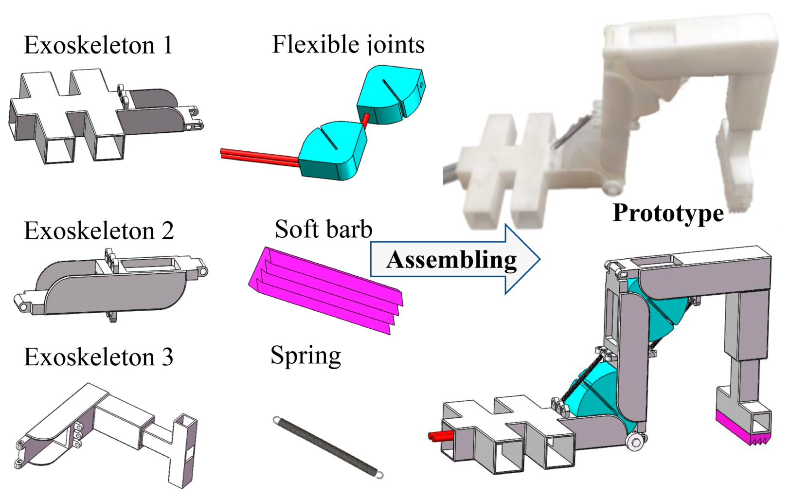
Besides the flexible joints, the other parts of the single-legged soft arthropod robot were all produced by the stereolithography 3D printer EP-A650A Pro. Figure 5 shows the assembling of the soft arthropod robot.
3. Modeling of Flexible Joint
3.1. Mathematical Model
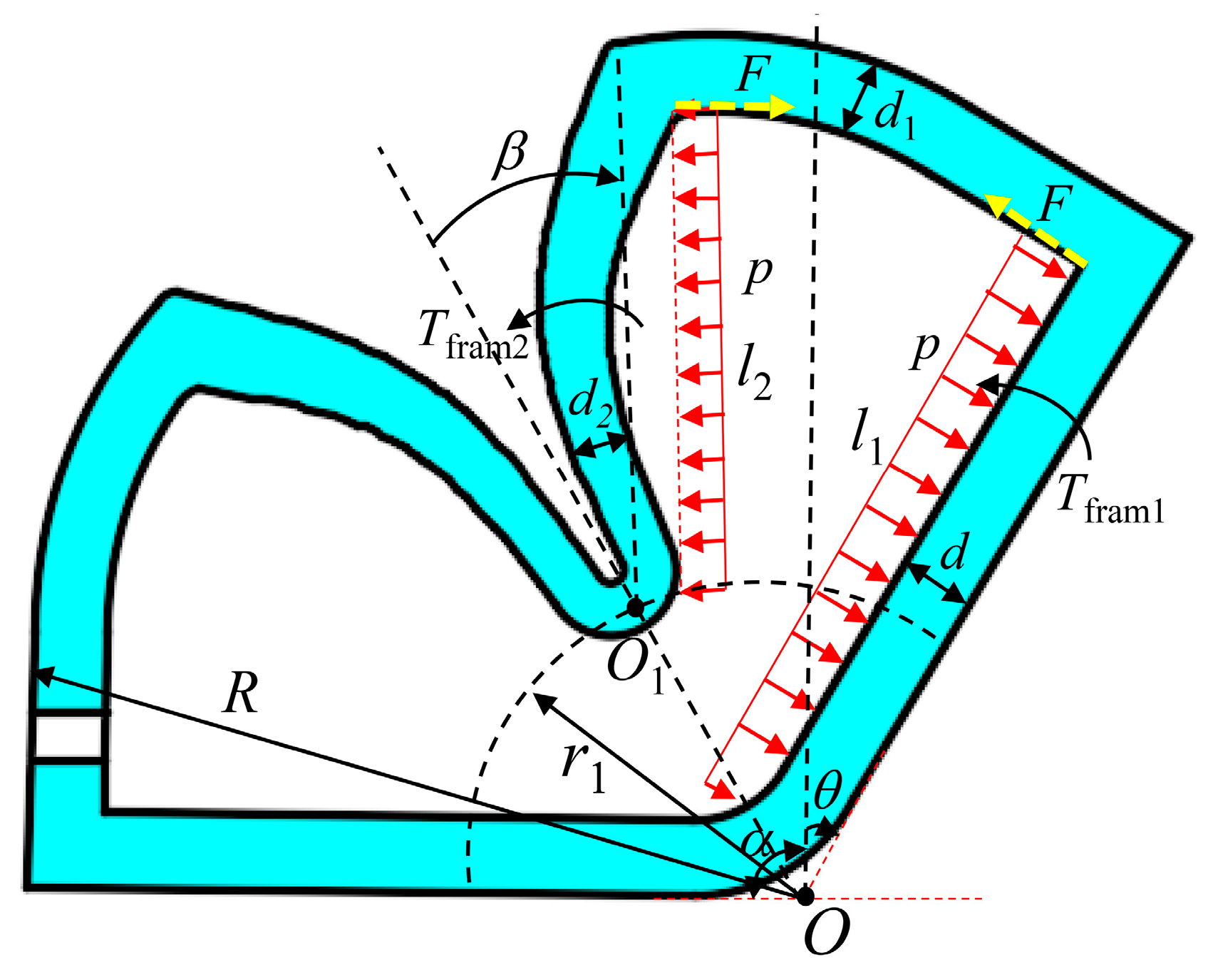
The mathematical model of the joint actuator concentrates on the rotation angle and torque. Figure 6 shows the force analysis diagram of the double-constrained pneumatic joint when the inflation pressure is p.
Since the two chambers are symmetrical, one of the chambers is used to illustrate the modeling process. Taking the point O as the center of rotation, the moment balance equation can be expressed as
where Tfram1 is the restoring moment of the basal layer, , E is the elastic modulus of silica gel, θ is the rotation angle of the joint. Tp1 is the acting moment on the basal layer of the air pressure, . Tr1 is the recovery moment of the base layer with radius r1, , α is the initial state angle, α = 90°. T1(R−r1) is the tensile moment of radius r1 to R parts to the basal layer. T1(d1) is the tensile moment of the top-wall layer to the basal layer. T1(R−r1) and T1(d1) not only act on the flexible substrate but also act on the inside wall layer.
The moment balance equation of O1 can be rewritten as
where Tfram2 is the recovery moment of the inside wall, . Tp2 is the acting moment of chamber pressure on the inside wall, . T2(R−r1) is the tensile moment of radius r1 to R parts to the inside wall. T2(d1) is the tensile moment of the top-wall layer to the inside wall. Assuming that
where Fl2 is the equivalent moment acting on the inside wall, and F is the equivalent force. Meanwhile, T1(R−r1) + T1(d1) can also be described as
Equation (5) can be derived through Equations (1)–(4)
Tfram1, Tfram2 and Tr1 were substituted into Equation (5)
As shown in Figure 6, the following geometric equation can be deduced as
By substituting Equation (7) into Equation (6), the relationship between the rotation angle θ and the air pressure p can be obtained by
where θ and p are the only unknown variables, and the rest are all known constants. θ is the rotation angle of the joint around point O, which increases with the inflating pressure p. The model expressed by Equation (8) was verified by FEM simulations in ABAQUS software and the experiment of rotation angle in the following chapters.
3.2. FEA Model
To further study the soft flexible joint, a finite element analysis model was also established. By using the material evaluation tool in ABAQUS, the average stress-strain data of silica gel were fitted into four different constitutive models, namely Mooney Rivlin, Ogden, Neo Hooke, and Yeoh models. According to the deviation degree of curve fitting, the Yeoh model was selected as the best constitutive model of silica gel material in this paper, with material parameter values of C10 = 0.024, C20 = 0.002, D1 = D2 = 0 obtained from the uniaxial tensile tests.
The strain energy function of the second order Yeoh model is shown in Equation (9):
where I1 is the deformation tensor invariant of silica gel.
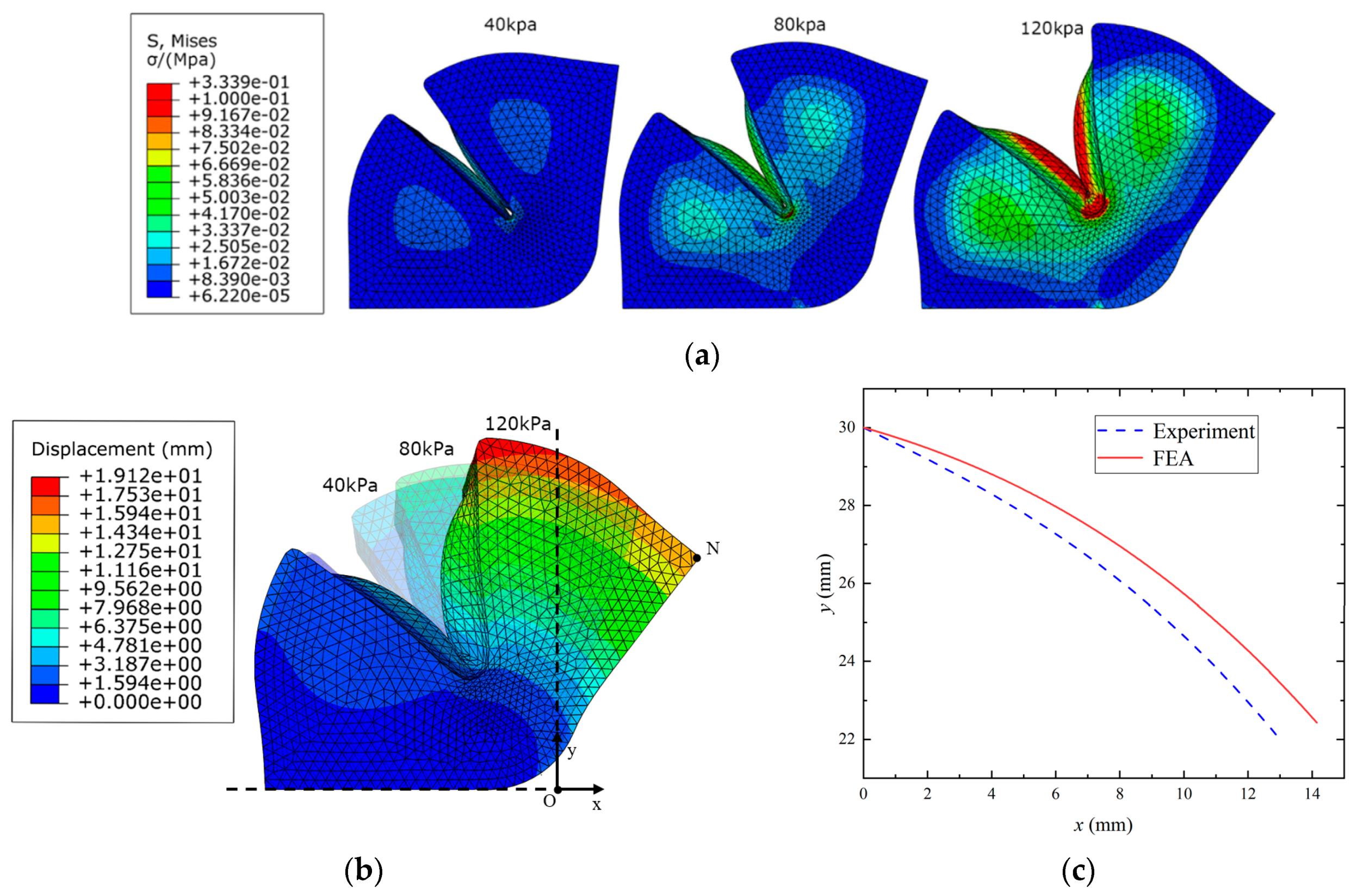
To protect the actuator from being damaged, the safe inflation pressure was set within 120 kPa. Figure 7a shows the strain analysis images of the double-constrained balloon under different inflation pressures of 40 kPa, 80 kPa, and 120 kPa, respectively. Figure 7b shows the displacement analysis nephogram under different inflation pressures. N(x,y) is the outermost point in the O(XY) coordinate system, its displacement trajectory was used to demonstrate the accuracy of the FEA model of the actuator. As shown in Figure 7c, there is a small deviation on N(x,y) trajectories between the FEA model and the experimental test, caused by the size error of the actuator in the fabrication process. The actual motion of the joint actuator can be predicted through the FEA simulation.
4. Experiments and Discussions
4.1. Rotation Angle
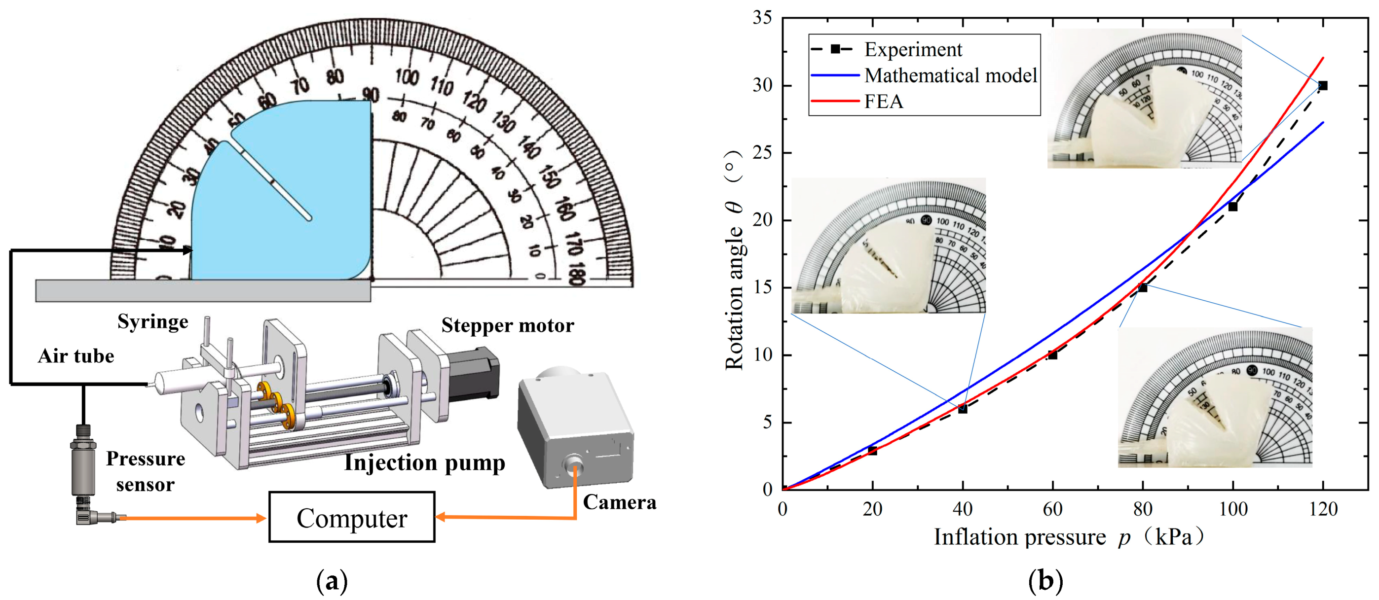
The rotation angle is a critical indicator to evaluate the joint actuator, which is measured in the experimental platform, as shown in Figure 8a. The platform is composed of a holding part, a precise inflation device, and an observation device. One of the basal layers in the actuator is bonded to a fixed plate, and the other can be freely extended under the action of compressed air. For ensuring the test stability, a precise injection pump (composed of a stepping motor, a ball screw propeller, and a 50 mL syringe) was used to charge compressed air at a constant speed of 2 mm/s. A precision gas pressure sensor (MIK-P310 with range of 0~0.6 MPa and accuracy level of 0.3) detected the inflation pressure of the flexible joint. The signals detected by the pressure sensor were collected by an Arduino controller with a sampling frequency of 10 Hz. The process of actuator deformation was recorded by a high-speed camera (Keyence VH-Z50L, set 2000 fps, magnification 50, and resolution 640 × 480). In order to ensure the accuracy of the experimental results, five samples of the actuator were made, and five inflation experiments were carried out, respectively, for each sample to obtain the average data as the experimental results.
Figure 8b shows the relationship between the joint rotation angle and inflation pressure. The experimental test, mathematical model, and FEA simulation are compared. When the inflation pressure is lower than 80 kPa, the FEA curve almost coincides with the experimental curve. When the inflation pressure increases from 80 kPa to 120 kPa, because of the fabrication error, the angle deviation increases gradually but the maximum error is within 2 degrees. Meanwhile, the rotation angle calculated by the mathematical model also shows good agreement with the experimental results.
4.2. Output Force
The output force is also an important indicator to evaluate the joint actuator, which is measured in the experimental platform as shown in Figure 9a. A complete joint is formed by a double-constrained balloon actuator and two-section exoskeletons. One of the exoskeletons is fixed by a clamp, and the other can rotate around the center of rotation. A high-precision force gauge SF-20N with range 0–20 N and resolution 0.01 N was horizontally placed at 40 mm away from the rotation center and close to the driver, which was used to detect the output force of the joint actuator. A precise injection pump (composed of a stepping motor, a ball screw propeller, and a 50 mL syringe) was also used to charge compressed air at a constant speed of 2 mm/s. A precise pressure regulating valve (AirTac GPR30008L with range 0.005 to 0.2 MPa) was used to control the inflation pressure. The inflation pressure was controlled by the pressure regulating valve, and the pressure gradually increased from 0 kPa to 120 kPa five times, respectively, conducted on five samples.
As shown in Figure 9b, the output force increases linearly with the increase of inflation pressure. At 120 kPa, the output force can reach 8.3 N, which can produce an output torque of about 0.33 Nm. Of course, the smaller the size of the joint actuator, the smaller the volume of the air chamber and the corresponding output force. The results of FEA simulation are consistent with the experimental results, and both increase linearly with the increase of air pressure. At the same inflation pressure, the output force of the FEA model is slightly less than the experimental results, and the maximum deviation is less than 0.3 N, which is in good agreement with the experimental results.
4.3. Efficiency
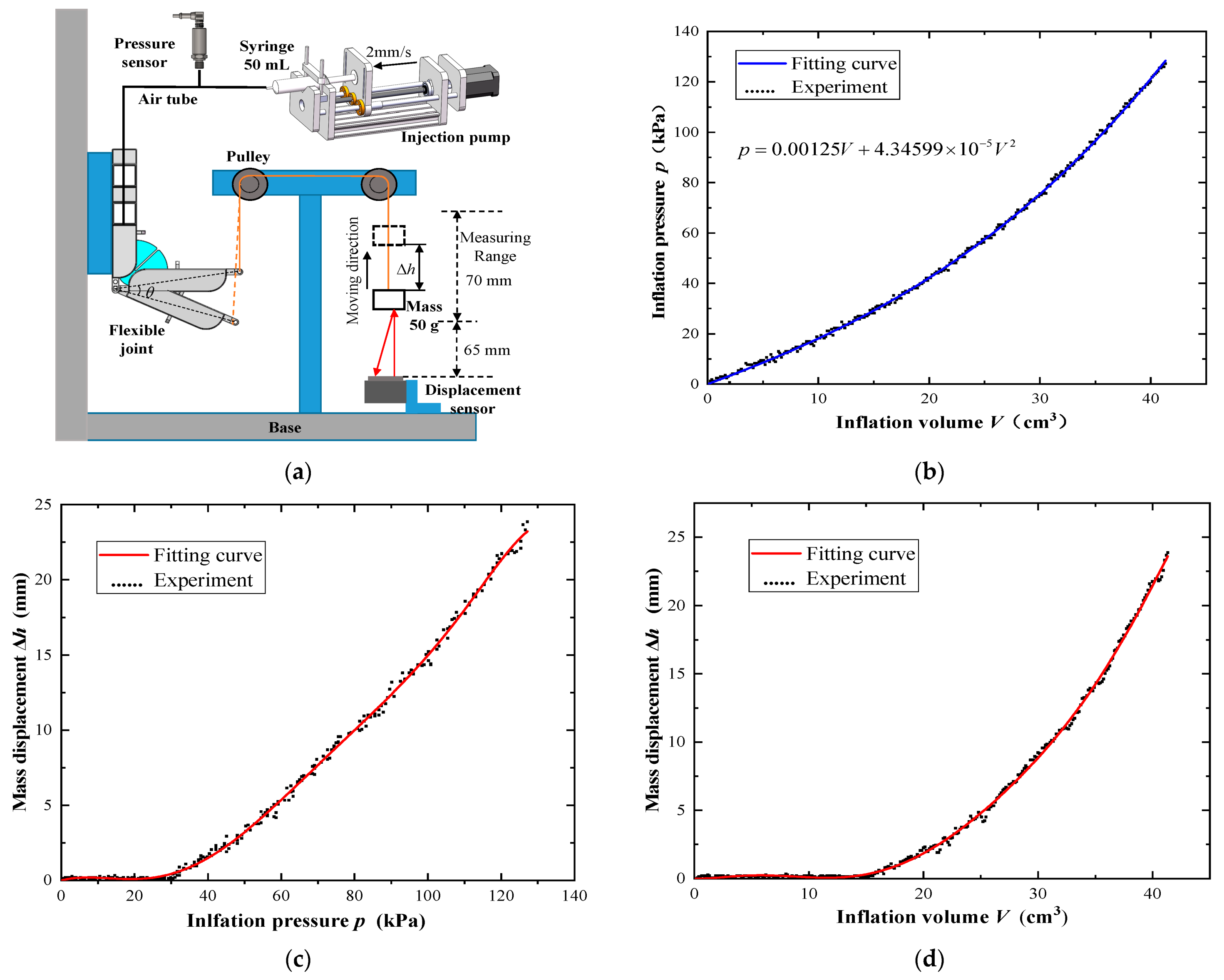
The efficient experimental platform is shown in Figure 10a. It mainly consists of a joint clamping mechanism, a pulley system, a gas injection mechanism, and a measuring mechanism. One end of the joint is fixed by a clamp, and the other end can be freely extended under the action of inflation pressure. Similar to the rotation angle experiments, the precise injection pump was also used to charge the joint at a constant speed of 2 mm/s. The precise pressure sensor MIK-P310 was used to detect the injected gas pressure, and a laser displacement sensor (Panasonic HG-C1100 with measuring range 65~135 mm, resolution 70 μm) was chosen to detect the mass displacement, thus the joint angle was calculated.
In the case of using m = 50 g weight mass, the signals detected by the pressure sensor and laser displacement sensor were collected by an Arduino controller with a sampling frequency of 10 Hz. The relationships between inflation volume V and pressure p, pressure p and mass displacement Δh, and inflation volume V and mass displacement Δh were obtained, as shown in Figure 10b–d.
As can be seen from Figure 10b, the inflation pressure in the joint actuator increases nonlinearly with the continuous injection of air. Due to the air compressibility and the strong nonlinearity of silica gel, there is an obvious time delay, as shown in Figure 10c, as the mass does not move when the inflation pressure is less than 30 kPa. As the inflation pressure continues to increase, there is a linear relationship between the mass displacement and inflation pressure. When the inflation pressure is 130 kPa, the maximum displacement of the mass reaches 24 mm. The time delay in Figure 10d is similar to that in Figure 10c, as the mass does not move when the inflation volume is less than 15 mL. As the inflation pressure increases, the mass displacement increases nonlinearly with the inflation volume. When the inflation volume is 42 mL, the mass displacement reaches 24 mm.
The efficiency η of the joint actuator is characterized by Equation (10):
where Q is the energy input, . W represents the energy output, which is used to drive the mass to produce a displacement without considering the energy loss of the pulley system, W = mgΔh, g = 9.8 m/s2.
As shown in Figure 10b, since the experimental data between the inflation pressure and volume are discrete, a second-order polynomial fitting expression is obtained by using MATLAB,
where the units of p and V are MPa and cm3, respectively.
The joint driving efficiencies of different displacements are calculated by Equation (10), as shown in Table 2.
Due to the intrinsic characteristics of the pneumatic drive mode, the joint efficiencies are generally very low. When the inflation volume is small, the pressure in the joint chamber has not been fully established because of the high compressibility of air, resulting in small mass displacement and poor efficiency. With the increase of inflation volume, the efficiency improves gradually, as shown by the efficiency of Δh = 21.7 mm, which is 55.6% higher than that of Δh = 4.2 mm.
4.4. Locomotion of Single-Legged Soft Arthropod Robot
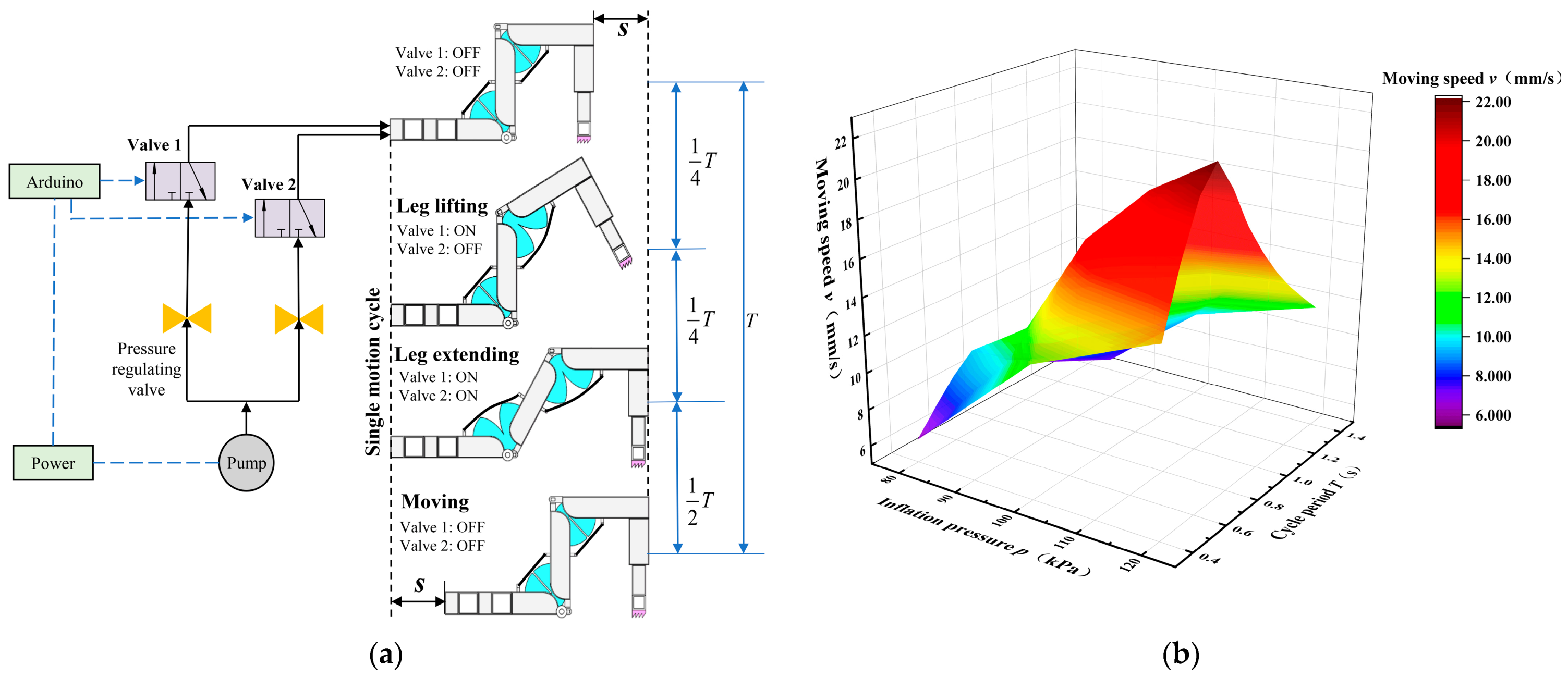
The proposed bio-inspired joint actuator was applied in the soft arthropod robot to test its locomotion performance, which was implemented by controlling the inflation and deflation of the two joint actuators. The locomotion process is periodic, corresponding to three actions of the robot, namely leg lifting, leg extending, andmoving, as shown in Figure 11a. The flexor spring shown here is not involved in the motion of the flexible joint. By controlling the inflation and deflation, the two joint actuators are continuously stretched and retracted, thus making the robot move in a straight line. The control system of robot locomotion is composed of an Arduino UNO controller, two precisely regulating valves (AirTac GPR30008L with range 0.005 to 0.2 MPa), and two pneumatic directional valves (AirTac 3V210-08NC).
The motion period T was adjusted from 0.4 s to 1.4 s by an Arduino controller. The air pressure was set as 80 kPa, 90 kPa, 100 kPa, 110 kPa, and 120 kPa by the pressure regulating valve, and the moving distances of the robot in different periods were measured under these five kinds of air pressure, then the relationship between the moving speed v, the motion period T and the inflation pressure p was obtained, as shown in Figure 11b.
The walking speed of the single-legged soft arthropod robot mainly depends on the pressure and cycle period of inflation and deflation as shown in Figure 11b. For analyzing the influence of inflation pressure and cycle period on walking speed, the walking distance of 20 locomotion cycles was measured, and then the walking speed could be calculated. Figure 11b shows the influence of inflation pressure and cycle on moving speed, respectively.
As shown in Figure 11b specifically, in the case of the same cycle period of inflation and deflation, the robot’s moving speed gradually increases with the increase of inflation pressure. The increasing trend shows three stages:
- When the inflation pressure is small (<90 kPa), the speed increases slowly due to the compressibility of the air;
- When the inflation pressure is in the range of 90 kPa to 110 kPa, the speed increases rapidly;
- When the inflation pressure is above 110 kPa, the speed increases slowly again.
Due to the limitation of structural deformation, the moving speed gradually increases and tends to be stable. It demonstrates that with the inflation pressure, bigger is not better. When the inflation pressure exceeds a certain level, the increase in the robot’s moving speed is limited, but it may significantly reduce the actuator’s life.
At the same time, a longer cycle period is not better. There is an optimal cycle period of T = 0.7 s, as demonstrated in Figure 11b. Under the conditions of inflation pressure 80 kPa, 100 kPa, and 120 kPa, the moving speed first increases and then decreases with the increase of the cycle period, and the moving speed reaches the fastest 22 mm/s with a cycle period of 0.7 s. This is because if the inflation speed and load are constant, the inflation time for the actuator to reach its preset pressure is determined. When the inflation time is less than this preset time, the air intake of the actuator chamber increases, thus making the inflation pressure increase and the moving speed increase. However, when the inflation time exceeds this time and the actuator chamber has reached the maximum air intake volume, the impact of gas charging on the moving speed is very limited with the increase of inflation time.
5. Conclusions
The proposed flexible actuator simplifies the joint structure and enhances exoskeleton protection, which is a promising way to realize the combination of dexterous structure and powerful drive capability. Furthermore, it also has the advantage of high scalability by using the combination of joints and limbs to develop different kinds of soft arthropod robots. The mathematical model and FEA model of the flexible joint were established and verified by experiments. The application results of the flexible joint on a single-legged soft arthropod robot show that the moving speed can reach 22 mm/s under the condition of inflation pressure 120 kPa and a cycle period of 0.7 s, which demonstrates the performance of the bio-inspired flexible joint actuator. The effect of flexor spring on flexible joints needs to be furthered studied to achieve the goal of hydraulic muscle co-drive.
In future work, the size parameters of the flexible joint actuator will be further optimized to improve the actuation performance. In addition, the actuator was only applied to the single-legged soft arthropod robot, the feasibility of which was demonstrated in the paper. Single-leg mode is a promising breach to study the soft arthropod robot, and multi-legged mode will be researched in the future, of course at the cost of more complicated fabrication and control.
Author Contributions
Conceptualization, M.X.; methodology, M.X.; software, C.R.; validation, C.R. and L.H.; formal analysis, L.H.; investigation, C.R.; resources, M.X. and C.R.; data curation, C.R.; writing—original draft preparation, C.R., L.H.; writing—review and editing, C.R.; supervision, M.X.; project administration, M.X.; funding acquisition, M.X. All authors have read and agreed to the published version of the manuscript.
Funding
This research was funded by the National Natural Science Foundation of China (Grant no. 51975171).
Institutional Review Board Statement
Not applicable.
Informed Consent Statement
Not applicable.
Data Availability Statement
All data generated or analyzed during this study are included in this article.
Acknowledgments
This research was supported by the National Natural Science Foundation of China (Grant no. 51975171).
Conflicts of Interest
The authors declare no conflict of interest.
References
- Palagi, S.; Fischer, P. Bioinspired microrobots. Nat. Rev. Mater. 2018, 3, 113–124. [Google Scholar] [CrossRef]
- Rus, D.; Tolley, M.T. Design, fabrication and control of soft robots. Nature 2015, 521, 467–475. [Google Scholar] [CrossRef] [PubMed] [Green Version]
- Hines, L.; Petersen, K.; Lum, G.Z.; Sitti, M. Soft Actuators for Small-Scale Robotics. Adv. Mater. 2017, 29, 1603483. [Google Scholar] [CrossRef] [PubMed]
- Wirekoh, J.; Parody, N.; Riviere, C.N.; Park, Y.-L. Design of fiber-reinforced soft bending pneumatic artificial muscles for wearable tremor suppression devices. Smart Mater. Struct. 2021, 30, 015013. [Google Scholar] [CrossRef]
- Manfredi, L.; Yue, L.; Zhang, J.; Cuschieri, A. A 4 DOFs variable stiffness soft module. In Proceedings of the 2018 IEEE International Conference on Soft Robotics (RoboSoft), Livorno, Italy, 24–28 April 2018; pp. 94–99. [Google Scholar]
- Gorissen, B.; Reynaerts, D.; Konishi, S.; Yoshida, K.; Kim, J.-W.; De Volder, M. Elastic Inflatable Actuators for Soft Robotic Applications. Adv. Mater. 2017, 29, 1604977. [Google Scholar] [CrossRef] [PubMed]
- Manfredi, L.; Putzu, F.; Guler, S.; Huan, Y.; Cuschieri, A. 4 DOFs hollow soft pneumatic actuator—HOSE. Mater. Res. Express 2018, 6, 045703. [Google Scholar] [CrossRef] [Green Version]
- Guan, Q.; Sun, J.; Liu, Y.; Leng, J. Status of and trends in soft pneumatic robotics. Sci. Sin. Technol. 2020, 50, 897–934. [Google Scholar]
- Ranzani, T.; Gerboni, G.; Cianchetti, M.; Menciassi, A. A bioinspired soft manipulator for minimally invasive surgery. Bioinspir. Biomimetics 2015, 10, 035008. [Google Scholar] [CrossRef] [PubMed]
- Ji, X.; Liu, X.; Cacucciolo, V.; Imboden, M.; Civet, Y.; El Haitami, A.; Cantin, S.; Perriard, Y.; Shea, H. An autonomous untethered fast soft robotic insect driven by low-voltage dielectric elastomer actuators. Sci. Robot. 2019, 4, eaaz6451. [Google Scholar] [CrossRef] [PubMed]
- Bernth, J.E.; Arezzo, A.; Liu, H. A Novel Robotic Meshworm with Segment-Bending Anchoring for Colonoscopy. IEEE Robot. Autom. Lett. 2017, 2, 1718–1724. [Google Scholar] [CrossRef] [Green Version]
- Wehner, M.; Truby, R.L.; Fitzgerald, D.J.; Mosadegh, B.; Whitesides, G.M.; Lewis, J.A.; Wood, R.J. An integrated design and fabrication strategy for entirely soft, autonomous robots. Nature 2016, 536, 451–455. [Google Scholar] [CrossRef] [PubMed]
- Manfredi, L.; Capoccia, E.; Ciuti, G.; Cuschieri, A. A Soft Pneumatic Inchworm Double balloon (SPID) for colonoscopy. Sci. Rep. 2019, 9, 1–9. [Google Scholar] [CrossRef] [PubMed] [Green Version]
- Cianchetti, M.; Mattoli, V.; Mazzolai, B.; Laschi, C.; Dario, P. A new design methodology of electrostrictive actuators for bio-inspired robotics. Sens. Actuators B Chem. 2009, 142, 288–297. [Google Scholar] [CrossRef]
- Siebert, T.; Weihmann, T.; Rode, C.; Blickhan, R. Cupiennius salei: Biomechanical properties of the tibia–metatarsus joint and its flexing muscles. J. Comp. Physiol. B 2010, 180, 199–209. [Google Scholar] [CrossRef] [PubMed]
- Kropf, C. Hydraulic system of locomotion. In Spider Ecophysiology; Springer: Berlin/Heidelberg, Germany, 2013. [Google Scholar]
- Foelix, R.F. Biology of Spiders; Oxford University Press: Oxford, UK, 2011. [Google Scholar]
- Zentner, L. Modelling and Application of the Hydraulic Spider Leg Mechanism. In Spider Ecophysiology; Springer: Berlin/Heidelberg, Germany, 2013. [Google Scholar]
- Berring, J.; Kianfar, K.; Lira, C.; Menon, C.; Scarpa, F. A smart hydraulic joint for future implementation in robotic structures. Robot. 2010, 28, 1045–1056. [Google Scholar] [CrossRef]
- Liu, C.; Chen, S.; Sheng, C.; Ding, P.; Qian, Z.; Ren, L. The art of a hydraulic joint in a spider’s leg: Modelling, computational fluid dynamics (CFD) simulation, and bio-inspired design. J. Comp. Physiol. A 2019, 205, 491–504. [Google Scholar] [CrossRef] [PubMed]
Figure 1.
Principle of hydraulic muscle co-drive joint. (a) Single leg of spider (illustrated in length scale); (b) Flexor-induced joint flexion; (c) Hydraulics-induced joint extension; (d) Bio-inspired flexible joint; (e) Flexion of proposed joint; (f) Extension of proposed joint.
Figure 1.
Principle of hydraulic muscle co-drive joint. (a) Single leg of spider (illustrated in length scale); (b) Flexor-induced joint flexion; (c) Hydraulics-induced joint extension; (d) Bio-inspired flexible joint; (e) Flexion of proposed joint; (f) Extension of proposed joint.

Figure 2.
Double-constrained balloon actuator.

Figure 3.
Structure of the soft arthropod robot with two flexible joints.

Figure 4.
Fabrication progress of the flexible joint.

Figure 5.
Assembling of the soft arthropod robot. (Including three exoskeletons produced by the stereolithography 3D printer, two springs, a soft barb, and two flexible joints made of silica gel).
Figure 5.
Assembling of the soft arthropod robot. (Including three exoskeletons produced by the stereolithography 3D printer, two springs, a soft barb, and two flexible joints made of silica gel).

Figure 6.
Force analysis of joint actuator.

Figure 7.
FEA simulation of flexible joint. (a) Strain analysis; (b) Displacement analysis; (c) N (x, y) trajectories.
Figure 7.
FEA simulation of flexible joint. (a) Strain analysis; (b) Displacement analysis; (c) N (x, y) trajectories.

Figure 8.
Rotation angle of flexible joint. (a) Experimental platform of rotation angle; (b) Comparison results.
Figure 8.
Rotation angle of flexible joint. (a) Experimental platform of rotation angle; (b) Comparison results.

Figure 9.
Test of output force. (a) Experimental platform of output force; (b) Comparison results.

Figure 10.
Efficiency test of joint actuator. (a) Efficiency experimental platform; (b) V-p fitting; (c) Δh-p fitting; (d) Δh-V fitting.
Figure 10.
Efficiency test of joint actuator. (a) Efficiency experimental platform; (b) V-p fitting; (c) Δh-p fitting; (d) Δh-V fitting.

Figure 11.
Locomotion test of single-legged soft arthropod robot. (a) Locomotion principle; (b) The influence of pressure and period on moving speed.
Figure 11.
Locomotion test of single-legged soft arthropod robot. (a) Locomotion principle; (b) The influence of pressure and period on moving speed.


Table 1.
Structural parameters of single-legged arthropod robot (mm).
| Parameter | B | g | L | H | a | w | R | w1 |
| Value | 60 | 17 | 150 | 80 | 75 | 15 | 30 | 9 |
| Parameter | r | l1 | l2 | d | d1 | d2 | d3 | u |
| Value | 27 | 24 | 15 | 3 | 3 | 2 | 3 | 0.5 |
Table 2.
Efficiency of joint actuator.
| Δh (mm) | 4.1 | 9.2 | 13.3 | 18.6 | 21.7 |
| Q (mJ) | 563 | 956 | 1294 | 1700 | 1928 |
| W (mJ) | 2.05 | 4.6 | 6.65 | 9.3 | 10.85 |
| η | 0.36% | 0. 48% | 0.51% | 0.54% | 0.56% |
Publisher’s Note: MDPI stays neutral with regard to jurisdictional claims in published maps and institutional affiliations. |
© 2021 by the authors. Licensee MDPI, Basel, Switzerland. This article is an open access article distributed under the terms and conditions of the Creative Commons Attribution (CC BY) license (https://creativecommons.org/licenses/by/4.0/).
Share and Cite
MDPI and ACS Style
Xu, M.; Rong, C.; He, L. Design and Modeling of a Bio-Inspired Flexible Joint Actuator. Actuators 2021, 10, 95. https://0-doi-org.brum.beds.ac.uk/10.3390/act10050095
AMA Style
Xu M, Rong C, He L. Design and Modeling of a Bio-Inspired Flexible Joint Actuator. Actuators. 2021; 10(5):95. https://0-doi-org.brum.beds.ac.uk/10.3390/act10050095
Chicago/Turabian StyleXu, Ming, Cheng Rong, and Long He. 2021. "Design and Modeling of a Bio-Inspired Flexible Joint Actuator" Actuators 10, no. 5: 95. https://0-doi-org.brum.beds.ac.uk/10.3390/act10050095
Note that from the first issue of 2016, this journal uses article numbers instead of page numbers. See further details here.