
A New Torque Distribution Control for Four-Wheel Independent-Drive Electric Vehicles


1
School of Mechanical Engineering, Nanjing University of Science and Technology, Nanjing 210094, China
2
Department of Greenergy, National University of Tainan, Tainan 700, Taiwan
*
Author to whom correspondence should be addressed.
Actuators 2021, 10(6), 122; https://0-doi-org.brum.beds.ac.uk/10.3390/act10060122
Submission received: 23 April 2021
/
Revised: 1 June 2021
/
Accepted: 2 June 2021
/
Published: 6 June 2021
(This article belongs to the Special Issue Actuators for Intelligent Electric Vehicles)
Abstract
:Torque distribution control is a key technique for four-wheel independent-drive electric vehicles because it significantly affects vehicle stability and handling performance, especially under extreme driving conditions. This paper, which focuses on the global yaw moment generated by both the longitudinal and the lateral tire forces, proposes a new distribution control to allocate driving torques to four-wheel motors. The proposed objective function not only minimizes the longitudinal tire usage, but also make increased use of each tire to generate yaw moment and achieve a quicker yaw response. By analysis and a comparison with prior torque distribution control, the proposed control approach is shown to have better control performance in hardware-in-the-loop simulations.
1. Introduction
Electric vehicles (EVs) are enjoying a wide distribution in road transportation not only thanks to their benefits for the environment [1], but also owing to their better dynamic performance [2].
Of the current EVs, four-wheel independent-drive electric vehicles (4WIDEVs), with motors installed in each wheel, have great advantages in generating both traction and braking torque quickly, accurately, and independently. These merits make 4WIDEVs an ideal platform for active chassis control, especially for direct yaw moment control (DYC). The DYC system, in contrast to four-wheel steering (4WS) and active front-wheel steering (AFS), utilizes the yaw moment directly generated by a reasonable distribution of longitudinal forces to adjust vehicle motion [3,4]. Therefore, as the basis of a DYC system, torque distribution control plays a key role in maintaining vehicle stability [5,6,7].
The early torque distribution control method for 4WIDEVs adopted a rule-based distribution method. Considering the tire characteristics, Shan formulated new rules to arrange the execution of actuators in a certain order [8]. Park took both the characteristic of independent wheel motor and tire friction circle into account and proposed a novel torque distribution algorithm based on daisy-chaining allocation [9]. Although it is easy to achieve this implementation, this kind of method, based on specific rules, had weak adaptability to the environment and low allocation accuracy. It faced difficulties in satisfying performance requirements under actual various driving conditions.
For this purpose, current research works have been adopting the optimal control theory to conduct torque distribution control to improve the control performance of DYC. For optimal control, it is very important to find the suitable objective function and constraints.
Joa and Feng proposed integration methods to minimize the allocation error, unintended braking, and tire slip [10,11]. However, in the critical situation in which DYC operates, it is more important to keep vehicles stable while passing through a curve quickly than to minimize tire dissipation or unintended deceleration.
Hori and Peng considered the sum of squares of longitudinal and lateral tire forces as an index to optimize torque distribution [12]. This method is very close to the concept of tire usage. Mokhiamar and Abe proposed the concept of tire workload usage first and built up an objective function. In the subsequent research works, a weight coefficient and more constraints were involved to improve the control performance [13,14]. The method-based tire usage rate relies on the idea that, the smaller the tire usage, the larger the margin left for lateral force and the more stable the vehicle. Ono introduced the tire grip margin coefficient, which minimized and equaled the usage of each tire. Additionally, this research proved the convergence of the proposed objective function [15]. Ignoring the uncontrollable lateral tire force, Yu took the constraints of the motor peak torque and road contact surface into account and defined a new objective function including the longitudinal tire force and weight coefficient [16]. Based on this research, Yang gave consideration to the relation between the lateral and longitudinal tire forces [17]. Wang added the constraint condition of longitudinal tire forces [18], and Guo also considered wheel slip ratio control for emergency conditions [19]. Li proposed a multifunctional optimization approach to simultaneously minimize the errors of force and moment at the center of gravity, actuator control efforts, and tire usage [20]. In addition to the driving safety object function, Huang also took drive system efficiency into account in their controller design [21]. Hu decoupled four-wheel torque vectoring and innovated a two-level distribution formula to reduce energy consumption while ensuring handling stability [22].
Nevertheless, these control designs based on tire usage devote the most effort to a single tire rather than on the rigid characteristics of 4WIDEVs. For example, in the curve scenario, even with the same tire usage, the left wheels have obvious differences from the right wheels in terms of their potential and contribution to global yaw moment. In the same way, the front and rear wheels also have different efficiencies in the generation of yaw moment. The simple consideration of tire usage cannot make full use of each tire to generate yaw moment. Thus, there is some space left for improving the DYC performance in 4WIDEVs.
Therefore, this paper, considering tire usage as well as the efficiency of global yaw moment generation, focuses on the development of a new torque distribution control system for 4WIDEVs. This system includes the models of yaw moment generation constructed for each tire and involves a new objective function to improve the DYC performance.
The rest of the paper is organized as follows. Section 2 describes the vehicle’s dynamic model. Section 3 proposes the optimal torque distribution control approach. Section 4 validates the effectiveness and real-time performance of the proposed approach in a hierarchical DYC system. Section 5 analyzes its implementation, compares it with a typical method on the basis of the optimal tire usage, and analyzes the reason for its higher performance in depth.
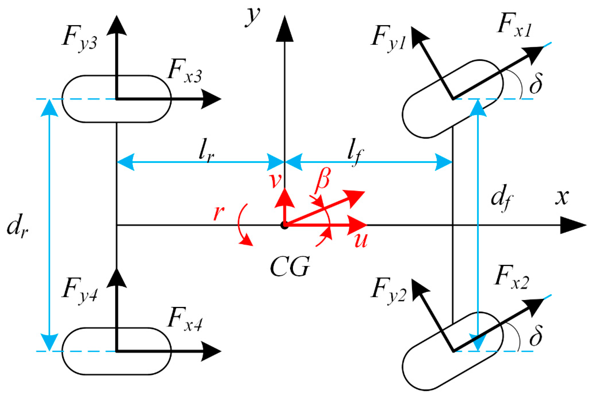
2. Vehicle Dynamic Model
A seven-degree-of-freedom (7-DOF) vehicle dynamic model—including the longitudinal, lateral, and yaw motion of the chassis as well as the rotation of the four wheels—was constructed for controller design. The chassis plane motion model is presented in Figure 1. Table 1 displays the definition of the notation used in the model.
The corresponding equations of vehicle planar motion are as follows:
The tire rotation dynamic equations can be described as
3. Controller Design
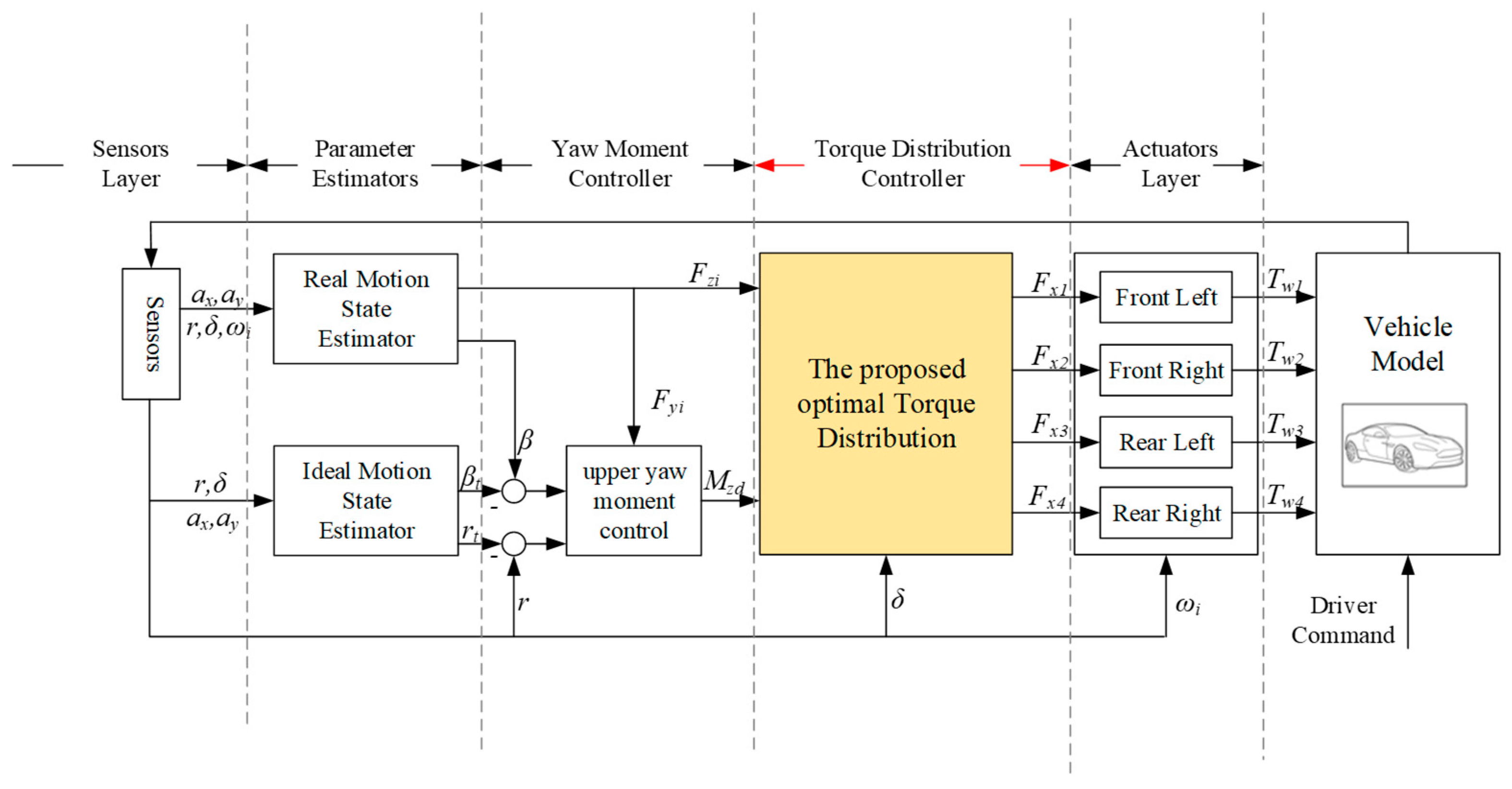
As illustrated in Figure 2, this study employed a hierarchical DYC system comprising three layers: a parameter estimator, yaw moment controller, and torque distribution controller. The parameter estimator uses measurable sensor signals to estimate the sideslip angle and tire forces [23,24]. The measured parameters include the longitudinal acceleration , lateral acceleration , yaw rate , wheel angular velocity , and steering wheel angle . The measured and estimated parameters are input to the upper yaw motion controller.
The upper yaw moment controller calculates the global yaw moment requirement on the CG to follow the desired sideslip angle and yaw rate and sends it as the equality constraint of the torque distribution controller.
Finally, the torque distribution controller allocates the optimal driving torque command to the four in-wheel motors to comply with the global yaw moment requirement.
3.1. Yaw Moment Controller
Thanks to its high robustness to sensor noise and variation in the vehicle state parameters, the sliding mode control method is easy to implement and widely used in vehicle stability controllers [25,26]. This study takes advantage of the sliding mode control method to design the yaw moment controller. The sliding surface is designed as
where and are the target yaw rate and sideslip angle, respectively, which can be obtained from a 2-DOF vehicle model [27]. and are the weight coefficients, and and are calculated as
where the parameters in (6) and (7) are listed in Table 1. For the convenience of calculation, the tire stiffness is replaced by an approximate fixed value. Owing to the limitation of road adhesion, the target yaw rate and sideslip angle have an upper limitation, which can be expressed as
where is the road friction coefficient and is assumed to be a constant.
The switching control law is designed as follows:
The control law presented in (10) eliminates the system chattering caused by the sign switching function at high frequencies.
The sliding surface (5) is derived as
The output of the upper yaw moment controller is set to . The yaw moment generated by longitudinal tire forces is easy to control directly, so it is suitable as the output of the upper yaw moment controller. Combined with Formulas (3), (10), and (11), the output is as follows:
According to the Lyapunov stability theory, in order to make the system stable, and are positive constants. The smaller is, the smaller the chattering is. For a good balance between response and stability, the values of the four control parameters (, , , and ) were tuned as 0.01, 50, 1.0, and −0.5 in the simulation, respectively.
Finally, the stability of the system using Formula (10) as the control law is analyzed. The stability is proven as follows:
Consider the Lyapunov function as follows:
By substituting the control law of Formula (10), the following can be obtained:
3.2. Torque Distribution Controller
In order to make full use of the lateral and longitudinal tire forces to generate the yaw moment, this paper proposes a new nonlinear optimal torque distribution control approach, with the objective function shown in (15). The ratio of the yaw moment generated by the longitudinal tire force to the global yaw moment, as well as the tire usage to be minimized, indicates that, in addition to the advantages of tire usage method, use is made of the lateral tire force to contribute as large a yaw moment as possible, and the rigid characteristics of 4WIDEVs have also been fully considered.
where is the longitudinal force of the th wheel ( = 1, 2, 3, and 4), is the vertical load of the th wheel ( = 1, 2, 3, and 4), is the yaw moment generated by the th in-wheel motor driving force, is the yaw moment generated from the th lateral tire force, and is the sum of and .
According to the 7-DOF vehicle dynamic model, and ( = 1, 2, 3, and 4) in (15) can be described as
Although the relation between the longitudinal and lateral tire forces can be approximately expressed as a friction ellipse, a simplified circle model with a safety factor is proposed to reduce the computation for actual implementation. is set to 0.8 in the formula to indicate that, even when the tire slip angle is large, the lateral force is not over estimated. The tire circle model is expressed as
where the th tire lateral force, , and traction/braking force, , are restricted by the friction coefficient multiplied by the vertical load .
In the equality constraints (19), the sum of yaw moment generated by the longitudinal tire forces is designed to meet the requirement of global yaw moment from the upper yaw moment controller.
The inequality constraints, including the motor peak torque and road adhesion constraints, can be expressed as follows:
where is the peak torque of the th in-wheel motor.
4. Simulation and Results
4.1. HIL Simulation System
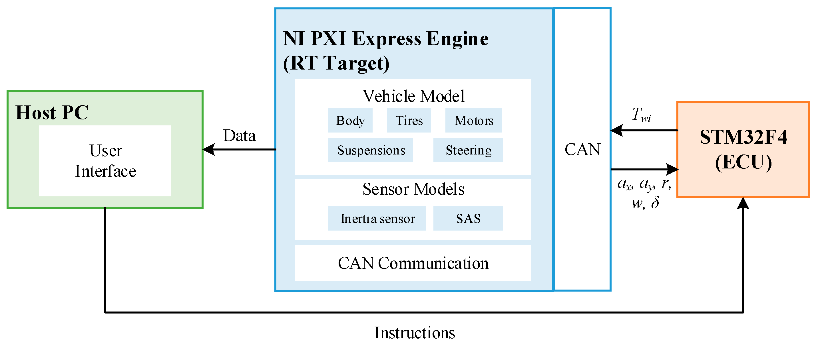
This paper used an HIL simulation to verify the effectiveness of the proposed optimal torque distribution approach. As illustrated in Figure 3, the HIL system comprises three subsystems: an NI PXI Express engine, an electronic control unit (ECU), and a host personal computer (PC).
- NI PXI Express Engine and models: The NI PXI Express engine contains different modular slots to simulate a vehicle model and sensor model. Detailed parameters of the PXI Express engine are provided in Table 2.
- ECU: The ECU is based on STM32F407ZGT6. The C code files of the yaw moment and torque distribution controllers are embedded in the ECU and calculate the target yaw moment and optimal motor torque exerted on each wheel. The step time is set to 5 ms.
- Host PC: The host PC is connected to the PXI Express by an Ethernet cable. The user interface on the PC is used to send a test command and display the vehicle state information.
This study develops a common C-class hatchback vehicle model in CarSim, which includes a chassis motion model, a steering system model, suspension rack models, tire models, and motor models. The vehicle parameters are listed in Table 3. The sensor models comprise a 6-DOF inertia sensor and a steering angle sensor model. Band-limited white noise signals are injected into the sensor models to simulate the noise in real sensors shown in Table 4.
4.2. HIL Simulation Results
4.2.1. Sine with Dwell
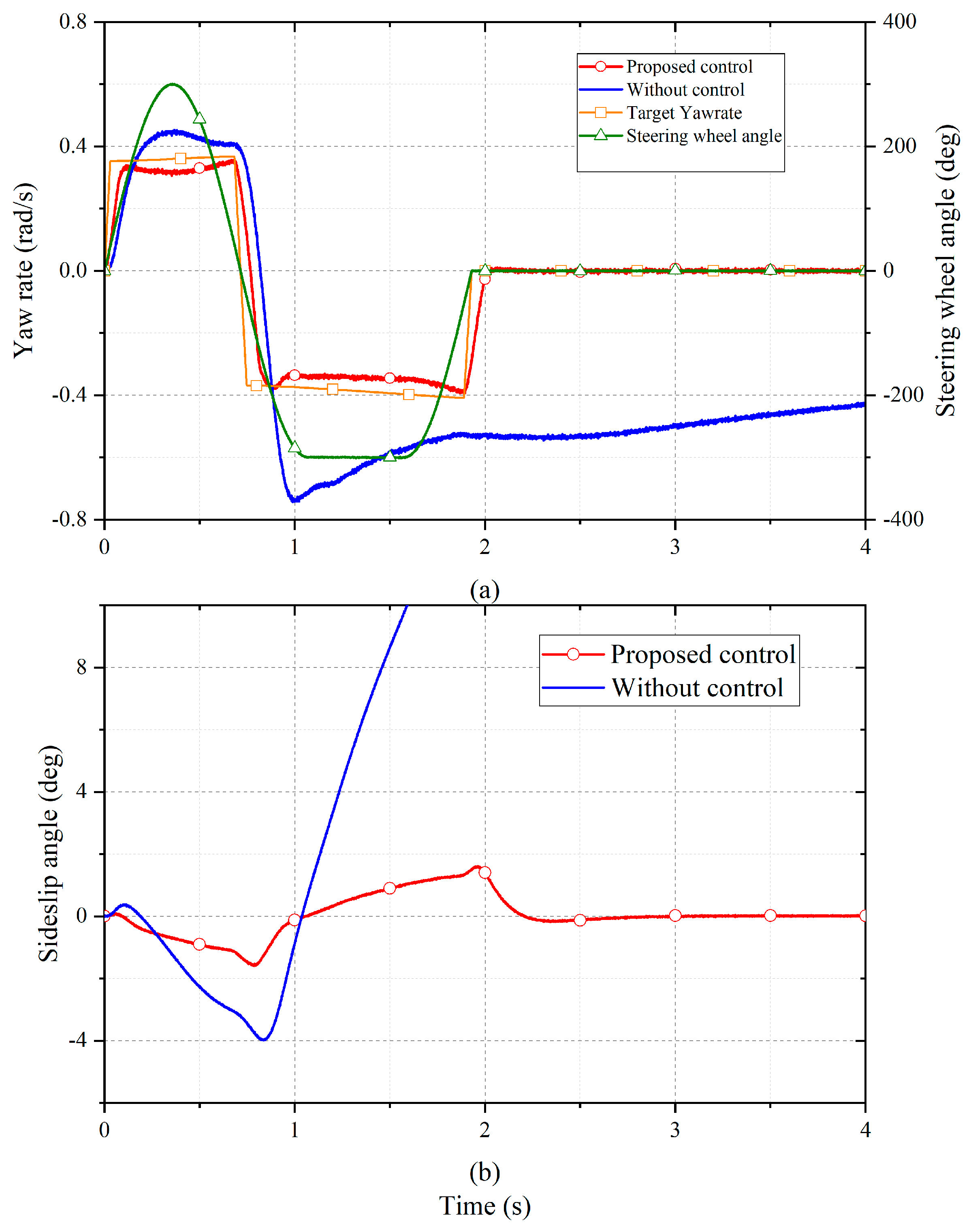
The Sine with Dwell (SWD) maneuver in the 126 requirements of the American Federal Motor Vehicle Safety Standard (FMVSS) was used to verify the effectiveness of the proposed optimal torque distribution method. The initial speed was set to 80 km/h and the friction coefficient was 0.8.
Figure 4 shows the yaw rate and sideslip angle responses of the vehicles with and without the proposed optimal torque distribution approach. As illustrated in Figure 4a, without control, the yaw rate was larger than 35% of its peak value. In contrast, with the proposed control, the yaw rate followed the variation in the steering wheel angle well, with its value reaching 20% of the peak value at 0.6 s after steering was completed. Table 5 shows the comparative evaluation of the SWD test. According to the FMVSS 126 requirements, it can be concluded that the vehicle with the proposed approach passed the test.
4.2.2. Double Lane Change
Closed-loop simulations were conducted at a constant speed of 60 km/h under road conditions with μ = 0.8.
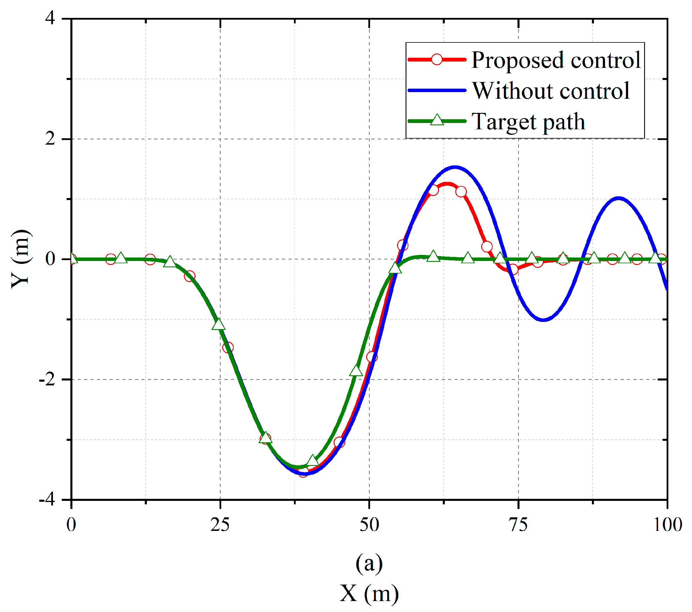
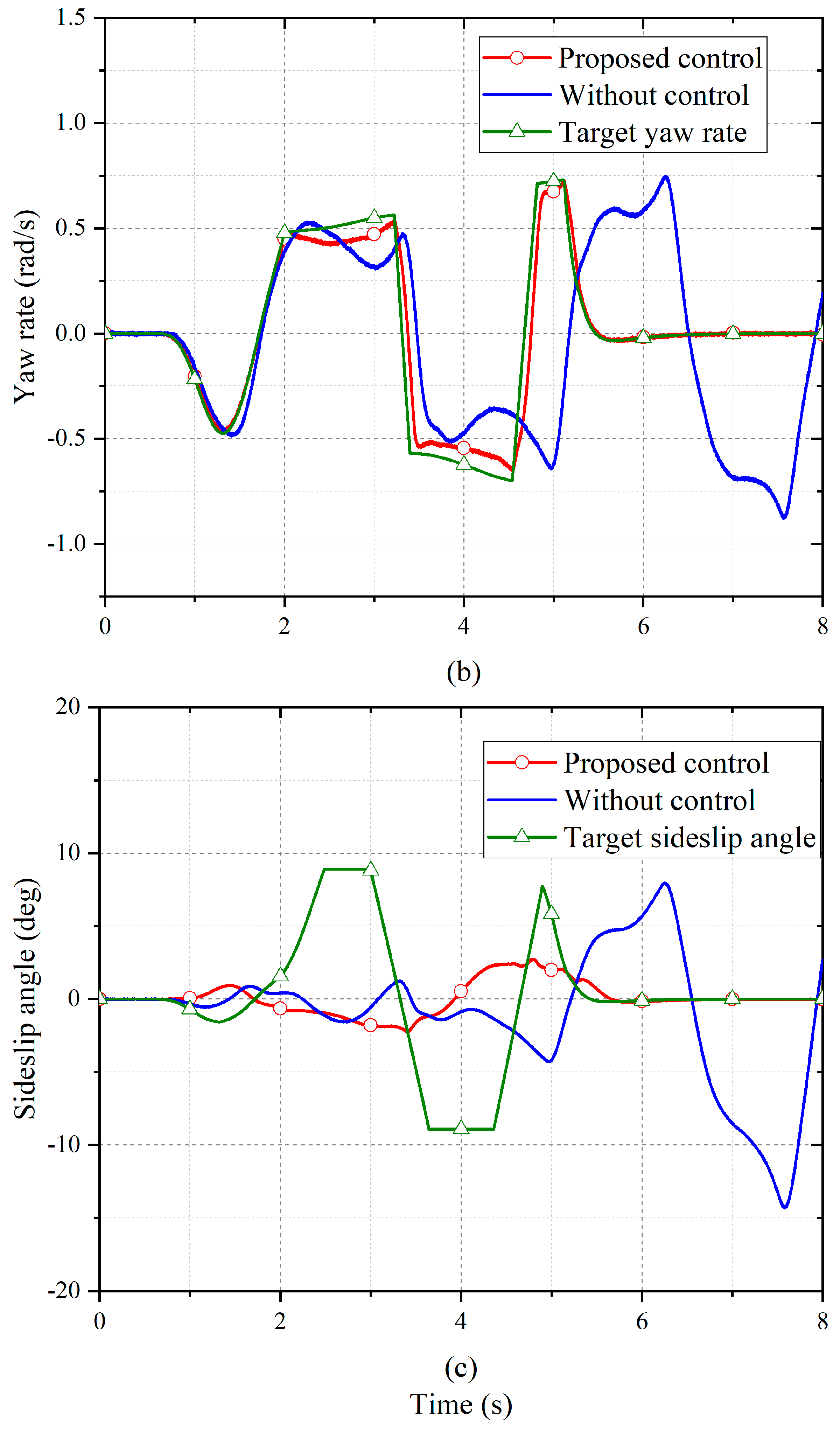
Figure 5a displays the vehicle’s trajectory. Figure 5b,c display the yaw rate and sideslip angle responses of the vehicles with and without the proposed optimal torque distribution approach. As illustrated in Figure 5a, the vehicle without control was not able to follow the expected trajectory. As illustrated in Figure 5b, without control, the yaw rate was constantly changing owing to the failure to follow the expected trajectory, meaning that the vehicle lost stability. By contrast, under the proposed control approach, the change of yaw rate was able to track the target yaw rate quickly and accurately, thus achieving vehicle stability control.
The detailed comparison in Figure 5c reveals that, when the control was not used, the sideslip angle increased rapidly after 5 s and ultimately exceeded the vehicle stability boundary. However, with the proposed control approach, the amplitude of the sideslip angle was always below 3° and changed smoothly, which means the vehicle could be easily handled by the driver.
5. Analysis and Discussion
5.1. Global Optimal Proof
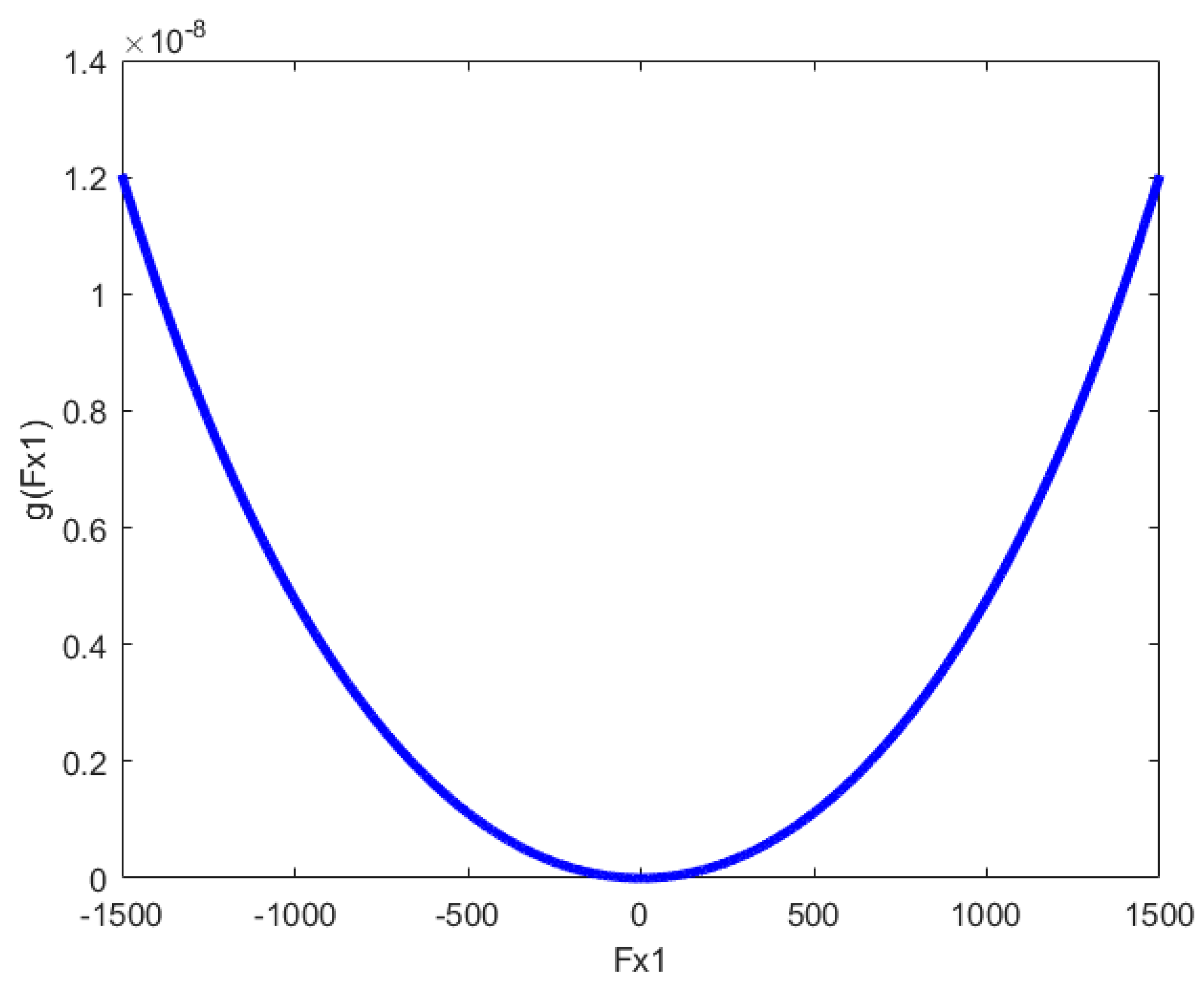
A global optimal solution can be obtained for convex optimization problems. In order to prove that the proposed algorithm is a convex optimization problem, it is necessary to prove that the proposed objective function is a convex function. It is assumed that the arm of yaw moments generated by longitudinal tire force and lateral tire force are and . The specific values of and are derived from (16) and (17). The objective function can be clearly expressed as (22), which can also be rewritten as (23). In the process of optimization, , , and are constants, where .
Taking as an example, in order to prove that (24) is a convex function in a simple and clear manner, the image of is described in Figure 6, which indicates that the proposed objective function is clearly a convex function in a feasible region. Similarly, it can be proved that the inequalities , , and are also true. In conclusion, the proposed objective optimization problem is a convex optimization problem and represents a suitable result for any driving condition.
.
5.2. Control Performance
This paper compares the proposed approach with the method based on the optimal tire usage rate [16] to discuss the reason behind the higher performance of the proposed approach.
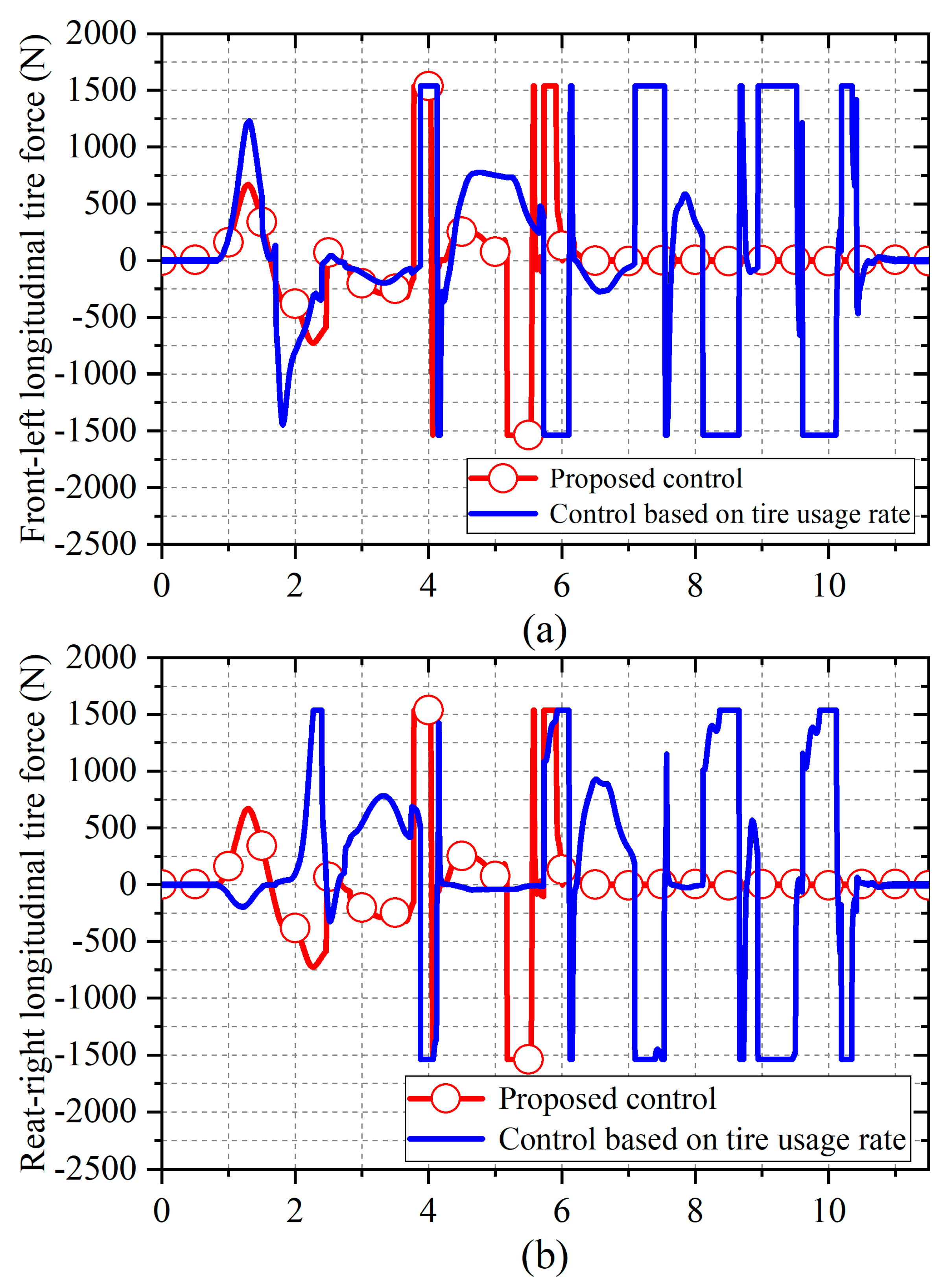
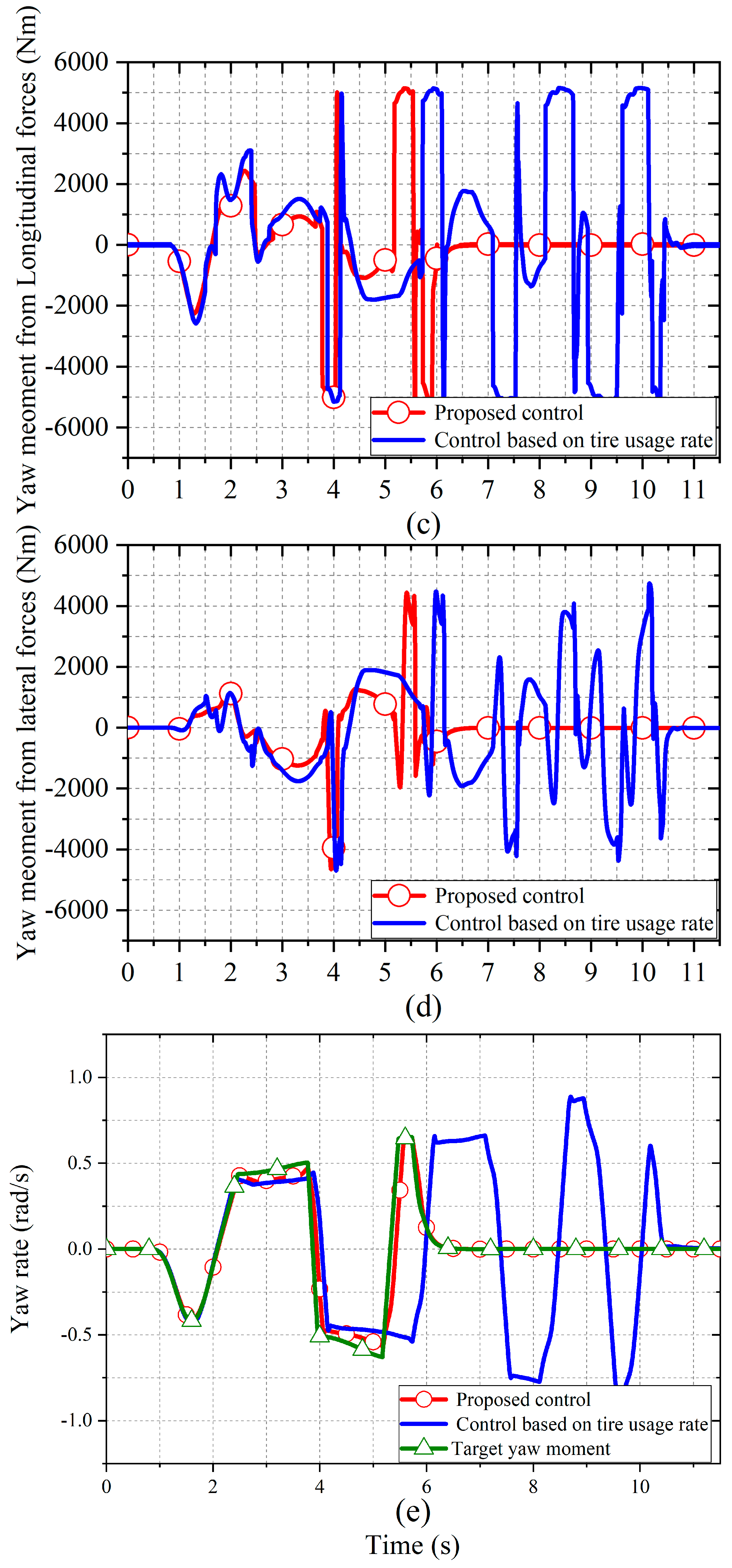
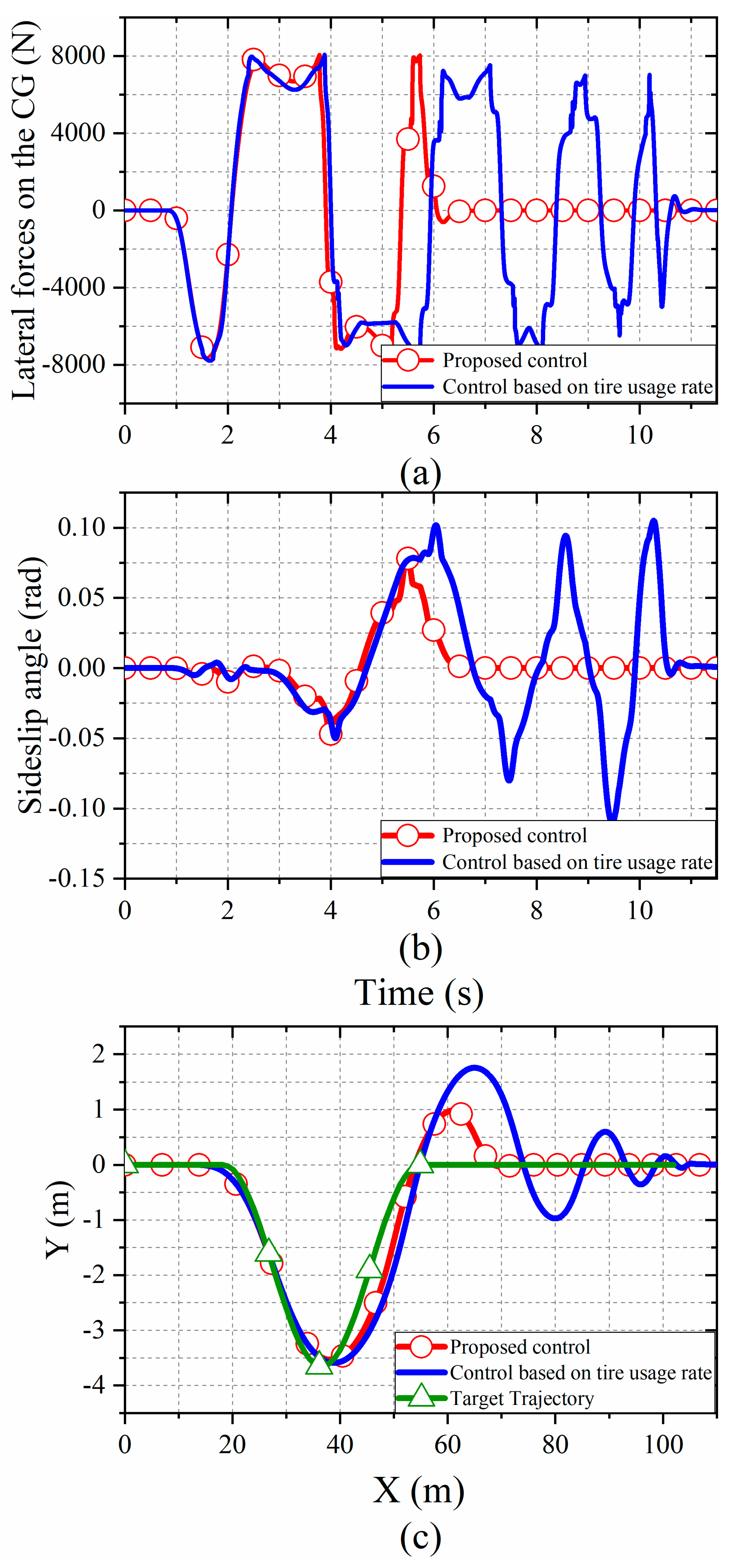
The simulation condition was a double-lane-change maneuver performed at 50 km/h, where the road adhesion coefficient was set to 0.6 for more comparable results. Figure 7 presents the analysis of the yaw moment generated by the motor driving forces and lateral tire forces. The results show that the proposed approach utilizes the lateral forces to generate yaw moment more fully and quickly, as well as to reduce the torque output of the four in-wheel motors. Figure 8 compares the CG lateral force, sideslip angle and driving trajectory to prove that the vehicle with the proposed torque distribution approach can follow the target trajectory better than with tire usage rate control.
Figure 7c,d display the yaw moments (Mz−x and Mz−y) generated by the motor driving forces and lateral tire forces, respectively. According to the results, the difference in the front-left and rear-right motor driving forces obtained for the two controllers is mainly caused by the yaw moment generated by the lateral forces. As shown in the Figure 7d, during 1.6–2.2 s, the proposed approach can use a larger Mz−y to compensate for the yaw moment generated from the motor driving forces when the sign of Mz−y is the same as that of Mz−x. Therefore, the Mz−x used to track the target yaw moment from the upper controller is smaller, and the torque output of the four in-wheel motors is also reduced. In addition, by comparing the curves of Mz−x and Mz−y during 1.2–1.5 s and 2.6–3.8 s, the proposed approach outputs a lower Mz−x when Mz−x and Mz−y have opposite signs, owing to the lower Mz−y.
Figure 7e presents a comparison of the yaw rate responses. Under the proposed method, the yaw rate can track the target value very well. The curve obtained under the tire usage rate control clearly has a delay and a larger fluctuation around 5.2 s. Moreover, it takes longer to converge to the stable state than in the proposed approach. In conclusion, the proposed approach makes better use of the lateral tire forces to generate the yaw moment and improves the vehicle yaw response.
Figure 8 illustrates the effect of CG lateral force on vehicle stability. As shown in Figure 8c, with the proposed control, the vehicle path is maintained within a smaller range and converges to the target trajectory more rapidly. Figure 8b, showing the comparative sideslip angle, shows the same conclusion. Figure 8a reveals that, with the proposed control method, the lateral force responds more quickly at 4.5 s, which causes the vehicle trajectory and sideslip angle to converge rapidly to a stable state.
6. Conclusions
For the purpose of improving the efficiency of yaw moment generation, this paper took the rigid characteristics of 4WIDEVs into full consideration and designed a control for torque distribution. This controller employed a new objective function, which considered tire usage and the efficiency of yaw moment generation.
The SWD results based on the HIL simulation demonstrated the effectiveness of our approach. The further analysis proved that this method gives suitable results for any driving condition, and the comparative simulation results in DLC experiments showed that the proposed method made quicker and fuller use of lateral force to generate yaw moment and gained better vehicle stability.
This approach has considerable value for distributed-drive EVs and can improve handling stability when negotiating curves. Moreover, the in-wheel motor with restrained torque output can also be used to achieve functions that enable great handling stability.
Author Contributions
D.Y. proposed the method and refined the manuscript; J.W. performed the experiments and prepared the original draft; J.D. and G.C. reviewed and supervised the manuscript; J.-S.H. provided software and experimental equipment support. All authors have read and agreed to the published version of the manuscript.
Funding
This work is supported by “Natural Science Foundation of Jiangsu Province”, BK20201307.
Institutional Review Board Statement
Not applicable.
Informed Consent Statement
Not applicable.
Data Availability Statement
Not applicable.
Conflicts of Interest
The authors declare no conflict of interest.
References
- Lin, C.-L.; Hung, H.-C.; Li, J.-C. Active Control of Regenerative Brake for Electric Vehicles. Actuators 2018, 7, 84. [Google Scholar] [CrossRef] [Green Version]
- Savitski, D.; Ivanov, V.; Augsburg, K.; Emmei, T.; Fuse, H.; Fujimoto, H.; Fridman, L.-M. Wheel Slip Control for the Electric Vehicle with In-Wheel Motors: Variable Structure and Sliding Mode Methods. IEEE Trans. Ind. Electron. 2020, 67, 8535–8544. [Google Scholar] [CrossRef]
- Zhang, L.; Ding, H.; Huang, Y.; Chen, H.; Guo, K.; Li, Q. An Analytical Approach to Improve Vehicle Maneuverability via Torque Vectoring Control: Theoretical Study and Experimental Validation. IEEE Trans. Veh. Technol. 2019, 68, 4514–4526. [Google Scholar] [CrossRef]
- Hang, P.; Xia, X.; Chen, X. Handling Stability Advancement With 4WS and DYC Coordinated Control: A Gain-Scheduled Robust Control Approach. IEEE Trans. Veh. Technol. 2021, 70, 3164–3174. [Google Scholar] [CrossRef]
- Kasinathan, D.; Kasaiezadeh, A.; Wong, A.; Khajepour, A.; Chen, S.-K.; Litkouhi, B. An Optimal Torque Vectoring Control for Vehicle Applications via Real-Time Constraints. IEEE Trans. Veh. Technol. 2016, 65, 4368–4370. [Google Scholar] [CrossRef]
- Shi, K.; Yuan, X.; Huang, G.; Liu, Z. Compensation-Based Robust Decoupling Control System for the Lateral and Longitudinal Stability of Distributed Drive Electric Vehicle. IEEE/ASME Trans. Mechatron. 2019, 24, 2768–2778. [Google Scholar] [CrossRef]
- Tan, D.; Lu, C. The Influence of the Magnetic Force Generated by the In-Wheel Motor on the Vertical and Lateral Coupling Dynamics of Electric Vehicles. IEEE Trans. Veh. Technol. 2016, 65, 4655–4668. [Google Scholar] [CrossRef]
- Shan, D.; Yin, D. A New Hierarchical Yaw Stability Control Approach for Four-Wheel Independent Driving Electric Vehicles. In Proceedings of the 35th Chinese Control Conference (CCC), Chengdu, China, 27–29 July 2016; pp. 4653–4657. [Google Scholar]
- Park, G.; Han, K.; Nam, K.; Kim, H.; Choi, S.-B. Torque Vectoring Algorithm of Electronic-Four-Wheel Drive Vehicles for Enhancement of Cornering Performance. IEEE Trans. Veh. Technol. 2020, 69, 3668–3679. [Google Scholar] [CrossRef]
- Joa, E.; Park, K.; Koh, Y.; Yi, K.; Kim, K. A Tyre Slip-Based Integrated Chassis Control of Front/Rear Traction Distribution and Four-Wheel Independent Brake from Moderate Driving to Limit Handling. Veh. Syst. Dyn. 2018, 56, 579–603. [Google Scholar] [CrossRef]
- Feng, J.; Chen, S.; Qi, Z. Coordinated Chassis Control of 4WD Vehicles Utilizing Differential Braking, Traction Distribution and Active Front Steering. IEEE Access 2020, 8, 81055–81068. [Google Scholar] [CrossRef]
- Peng, H.; Hori, Y. Optimum Traction Force Distribution for Stability Improvement of 4WD EV in Critical Driving Condition. In Proceedings of the 9th IEEE International Workshop on Advanced Motion Control, Istanbul, Turkey, 27–29 March 2006; pp. 596–600. [Google Scholar]
- Abe, M.; Mokhiamar, O. An Integration of Vehicle Motion Controls for Full Drive-by-Wire Vehicle. Proc. Ins. Mech. Eng. Part K J. Multi-Body Dyn. 2007, 221, 117–127. [Google Scholar] [CrossRef]
- Mokhiamar, O.; Abe, M. Combined Lateral Force and Yaw Moment Control to Maximize Stability as well as Vehicle Responsiveness During Evasive Maneuvering for Active Vehicle Handling Safety. Veh. Syst. Dyn. 2016, 37, 246–256. [Google Scholar] [CrossRef]
- Ono, E.; Hattori, Y.; Muragishi, Y.; Koibuchi, K. Vehicle Dynamics Integrated Control for Four-Wheel-Distributed Steering and Four-Wheel-Distributed Traction/Braking Systems. Veh. Syst. Dyn. 2007, 44, 139–151. [Google Scholar] [CrossRef]
- Xiong, L.; Yu, Z.; Wang, Y.; Yang, C.; Meng, Y. Vehicle Dynamics Control of Four In-Wheel Motor Drive Electric Vehicle Using Gain Scheduling Based on Tyre Cornering Stiffness Estimation. Veh. Syst. Dyn. 2012, 50, 831–846. [Google Scholar] [CrossRef]
- Yang, P. A Study on Multi-Actuators Control Allocation of Distributed Drive Electric Vehicle for Handling and Stability. Ph.D. Thesis, Tongji University, Shanghai, China, 2015. [Google Scholar]
- Wang, X. Optimal Torque Distribution of Four-Wheel Independent Drive Electric Vehicle Under Steering Condition. Master’s Thesis, Jilin University, Changchun, China, 2017. [Google Scholar]
- Guo, L.; Ge, P.; Sun, D. Torque Distribution Algorithm for Stability Control of Electric Vehicle Driven by Four In-Wheel Motors Under Emergency Conditions. IEEE Access 2019, 7, 104737–104748. [Google Scholar] [CrossRef]
- Li, B.; Goodarzi, A.; Khajepour, A.; Chen, S.-K.; Litkouhi, B. An Optimal Torque Distribution Control Strategy for Four-Independent Wheel Drive Electric Vehicles. Veh. Syst. Dyn. 2015, 53, 1172–1189. [Google Scholar] [CrossRef]
- Huang, J.; Liu, Y.; Liu, M.; Cao, M.; Yan, Q. Multi-Objective Optimization Control of Distributed Electric Drive Vehicles Based on Optimal Torque Distribution. IEEE Access 2019, 7, 16377–16394. [Google Scholar] [CrossRef]
- Hu, X.; Chen, H.; Li, Z.; Wang, P. An Energy-Saving Torque Vectoring Control Strategy for Electric Vehicles Considering Handling Stability Under Extreme Conditions. IEEE Trans. Veh. Technol. 2020, 69, 10787–10796. [Google Scholar] [CrossRef]
- Li, X.; Chan, C.; Wang, Y. A Reliable Fusion Methodology for Simultaneous Estimation of Vehicle Sideslip and Yaw Angles. IEEE Trans. Veh. Technol. 2016, 65, 4440–4458. [Google Scholar] [CrossRef]
- Rezaeian, A.; Zarringhalam, R.; Fallah, S.; Melek, W.; Khajepour, A.; Chen, S.-K.; Moshchuck, N.; Litkouhi, B. Novel Tire Force Estimation Strategy for Real-Time Implementation on Vehicle Applications. IEEE Trans. Veh. Technol. 2015, 64, 2231–2241. [Google Scholar] [CrossRef]
- Ni, J.; Hu, J.; Xiang, C. Envelope Control for Four-Wheel Independently Actuated Autonomous Ground Vehicle Through AFS/DYC Integrated Control. IEEE Trans. Veh. Technol. 2017, 66, 9712–9726. [Google Scholar] [CrossRef]
- Hu, J.; Tao, J.; Xiao, F.; Niu, X.; Fu, C. An Optimal Torque Distribution Control Strategy for Four-Wheel Independent Drive Electric Vehicles Considering Energy Economy. IEEE Access 2019, 7, 141826–141837. [Google Scholar] [CrossRef]
- Wang, Q.; Zhao, Y.; Deng, Y.; Xu, H.; Deng, H.; Lin, F. Optimal Coordinated Control of ARS and DYC for Four-Wheel Steer and In-Wheel Motor Driven Electric Vehicle with Unknown Tire Model. IEEE Trans. Veh. Technol. 2020, 69, 10809–10819. [Google Scholar] [CrossRef]
Figure 1.
Vehicle plane motion model.

Figure 2.
Hierarchical direct yaw moment control (DYC) system.

Figure 3.
Structure of the HIL simulation system. ECU, electronic control unit; PC, personal computer.
Figure 3.
Structure of the HIL simulation system. ECU, electronic control unit; PC, personal computer.

Figure 4.
Comparison of the vehicles with and without the proposed optimal torque distribution control: (a) yaw rate responses; (b) sideslip angle responses.
Figure 4.
Comparison of the vehicles with and without the proposed optimal torque distribution control: (a) yaw rate responses; (b) sideslip angle responses.

Figure 5.
Comparison of the vehicles with and without the proposed optimal torque distribution control method: (a) path tracking; (b) yaw rate responses; (c) sideslip angle responses.
Figure 5.
Comparison of the vehicles with and without the proposed optimal torque distribution control method: (a) path tracking; (b) yaw rate responses; (c) sideslip angle responses.


Figure 6.
Image of .

Figure 7.
Comparison of the simulation results between the vehicle with the use of the proposed control and the optimal tire usage rate control: (a,b) front−left and rear−right motor driving forces; (c,d) center of gravity (CG) yaw moment from the motor driving forces and the lateral tire forces; (e) yaw rate responses.


Figure 8.
Comparison of the vehicles using the proposed control and the optimal tire usage rate control: (a) CG lateral force; (b) sideslip angle responses; (c) vehicle trajectory.
Figure 8.
Comparison of the vehicles using the proposed control and the optimal tire usage rate control: (a) CG lateral force; (b) sideslip angle responses; (c) vehicle trajectory.


Table 1.
Definitions of symbols used in modeling.
| Symbols | Definitions | Unit |
|---|---|---|
| CG | Center of gravity | |
| Cf | Cornering stiffness of front wheels | |
| Cr | Cornering stiffness of rear wheels | |
| df | Front track width | |
| dr | Rear track width | |
| Fxi | Longitudinal force of the ith tire | |
| Fyi | Lateral force of the ith tire | |
| Iw | Rotational inertia of the wheel | |
| Iz | Yaw moment of inertia of the vehicle | |
| lf | Distance from CG to front axle | |
| lr | Distance from CG to rear axle | |
| l | Distance from front axle to rear axle | |
| m | Vehicle mass | |
| Reff | Wheel effective radius | |
| Twi | Motor torque on the ith wheel | |
| u | Vehicle longitudinal velocity | |
| v | Vehicle lateral velocity | |
| r | Yaw rate | |
| Sideslip angle | ||
| Steering wheel angle | ||
| Wheel rotational speed |
Table 2.
Parameters of the NI PXI engine.
| Product | Module | Specification |
|---|---|---|
| PXIe-1071 | PXI Chassis | Four-Slot, up to 3 GB/s |
| PXIe-8821 | Controller | 2.6 GHz dual-core processer |
| PXI-8512 | CAN Interface | Flexible data rate, high-speed |
| PXIe-6738 | Analog Output | 16 bit, 32 channel, 1 MS/s |
Table 3.
Vehicle parameters.
| Parameters | Values |
|---|---|
| Vehicle mass | 1412 |
| Sprung mass | 1270 |
| Height of center of gravity (CG) | 0.540 |
| Wheel base | 2.910 |
| Distance from CG to front axle | 1.015 |
| Distance from CG to rear axle | 1.895 |
| Track width | 1.675 |
| Vehicle yaw inertia | 1536.7 |
| Wheel inertia | 0.9 |
| Wheel effective radius | 0.325 |
Table 4.
Noise signals.
| Signal | Amplitude | Reference |
|---|---|---|
| δ | 6.3° | HiTech SAS (Steering Angle Sensor), HiRain |
| ax, ay | 0.049 m/s2 | Technologies Co., Ltd., Beijing, China |
| r | 1 deg/s | TAMAGAWA AU7428N200, TAMAGAWA |
| 10 rpm | SEIKI Co., Ltd., Nagano Prefecture, Japan |
Table 5.
Evaluation of the Sine with Dwell (SWD) test.
| Yaw Rate | Vehicle with the Proposed Control Method | Vehicle without Any Control |
|---|---|---|
| Peak value | −0.431 rad/s | −0.736 rad/s |
| 35% of the peak value | −0.151 rad/s | −0.258 rad/s |
| 1 s after completing steering | −0.003 rad/s | −0.505 rad/s |
| 20% of the peak value | −0.086 rad/s | −0.147 rad/s |
| 1.75 s after completing steering | +0.003 rad/s | −0.450 rad/s |
Publisher’s Note: MDPI stays neutral with regard to jurisdictional claims in published maps and institutional affiliations. |
© 2021 by the authors. Licensee MDPI, Basel, Switzerland. This article is an open access article distributed under the terms and conditions of the Creative Commons Attribution (CC BY) license (https://creativecommons.org/licenses/by/4.0/).
Share and Cite
MDPI and ACS Style
Yin, D.; Wang, J.; Du, J.; Chen, G.; Hu, J.-S. A New Torque Distribution Control for Four-Wheel Independent-Drive Electric Vehicles. Actuators 2021, 10, 122. https://0-doi-org.brum.beds.ac.uk/10.3390/act10060122
AMA Style
Yin D, Wang J, Du J, Chen G, Hu J-S. A New Torque Distribution Control for Four-Wheel Independent-Drive Electric Vehicles. Actuators. 2021; 10(6):122. https://0-doi-org.brum.beds.ac.uk/10.3390/act10060122
Chicago/Turabian StyleYin, Dejun, Junjie Wang, Jinjian Du, Gang Chen, and Jia-Sheng Hu. 2021. "A New Torque Distribution Control for Four-Wheel Independent-Drive Electric Vehicles" Actuators 10, no. 6: 122. https://0-doi-org.brum.beds.ac.uk/10.3390/act10060122
Note that from the first issue of 2016, this journal uses article numbers instead of page numbers. See further details here.