
Modular Capsules with Assembly and Separation Mechanism: Proof of Concept
by
 , ,
, ,
Zhenyu Li
1,2, 
Manh Cuong Hoang
1,2,
Chang-Sei Kim
1,2,*,
Eunpyo Choi
1,2,
Doyeon Bang
1,3,
Jong-Oh Park
1,2,* and
Byungjeon Kang
1,3,* 1
Korea Institute of Medical Microrobotics, Gwangju 506813, Korea
2
School of Mechanical Engineering, Chonnam National University, Gwangju 61186, Korea
3
Robotics Engineering Convergence, Chonnam National University, Gwangju 61186, Korea
*
Authors to whom correspondence should be addressed.
Actuators 2021, 10(7), 159; https://0-doi-org.brum.beds.ac.uk/10.3390/act10070159
Submission received: 27 May 2021
/
Revised: 30 June 2021
/
Accepted: 9 July 2021
/
Published: 12 July 2021
(This article belongs to the Special Issue Smart Actuators for Endoscopic Robots)
Abstract
:As wireless capsule endoscope (WCE) technology has advanced, various studies were published on WCEs with functional modules for the diagnosis and treatment of problems in the digestive system. However, when additional functional modules are added the physical size of the WCEs will increase, making them more difficult for patients to comfortably swallow. Moreover, there are limitations when it comes to adding multi-functional modules to the WCEs due to the size of the digestive tract itself. This article introduces a controllable modular capsule endoscope driven by an electromagnetic actuation (EMA) system. The modular capsules are divided into a driving capsule and a functional capsule. Capsules with different functions are swallowed in sequence and then recombination, transportation and separation functions are carried out under the control of the EMA system while in the stomach, this approach solves the size limitation issues faced by multi-functional capsule endoscopes. The recombination and separation functions make use of a characteristic of soft magnetic materials so that their magnetization direction can be changed easily. These functions are made possible by the addition of a soft magnet to the capsule together with the precise control of magnetic fields provided by the EMA system.
1. Introduction
The emergence of WCEs has received a great deal of attention due to the large leap in convenience and comfort they provide to patients undergoing gastrointestinal diagnostic procedures [1]. However, current WCEs are limited in application to diagnose conditions of the small bowel and esophagus. The reason for this is that they can only be moved by the peristalsis of the digestive tract, thus, clinicians cannot examine the digestive system in real-time. In order to enhance these capsules’ limited mobility, movable capsule endoscopes controlled by EMA were proposed. EMA systems operate based on their ability to manipulate magnetic fields by regulating current in coils [2,3,4,5]. The magnetic field generated by the coils controls the movement of the WCE, which includes a permanent magnet. Several EMA systems have been applied in actual clinical practice [6,7,8]. In addition, WCEs integrated with diagnostic or therapeutic functions have been widely studied including WCEs with functional modules such as pH detection [9], targeted drug delivery [10], in vivo labeling [11], digestive tract biopsy [12,13], etc. [14,15,16,17]. However, even commercialized WCEs are reported to have sometimes failed during their diagnostic procedures. A clinical review of WCEs pointed out that 16% of capsules used have problems passing through the gastrointestinal tract or are unable to pass through the gastrointestinal tract [18]. As such, we can see any further increase in size is the main limitation that hinders the multi-functionalization of WCEs.
One approach to tackle this size issue is the modularization of capsule endoscopes. Shuxiang Guo et al. [19] proposed a spiral modular capsule controlled by an EMA system that could carry out assembly and separation functions in a pipeline. However, the spiral modular capsule has a limitation in controlling the capsule’s movement because it can only move along the inner wall of the water-filled pipeline. Laehyun Kim et al. [20] proposed a motor-driven modular capsule that successfully achieved assembly and separation in a pipeline using a mechanical structure. A wireless charging module was added to solve the energy consumption of the motor, but the disadvantage is that the capsule module becomes too large. Additionally, its mechanical structure design makes it move only within the tubular structure, which limits its DOF. Zoltan Nagy et al. [21] designed a reconfigurable endoluminal surgical system using modular robots with self-alignment and docking functions. This capsule has a complex structure consisting of many components for its reconfiguration, such as a motor-driven steering system. Kanako Harada et al. [22] designed a reconfigurable modular robot system driven by a motor, they adopted a design similar to Z. Nagy et al., with complex mechanical structures. Seung-Schik Yoo et al. [23] proposed a motor-driven modular capsule where multiple capsules could assemble on a plane. The capsules have good assembly performance, but are very bulky and have high energy consumption. The pioneers of these modular capsules promoted the development of modular capsules to varying degrees, the advantages and limitations of these modular capsules are compared in Table 1.
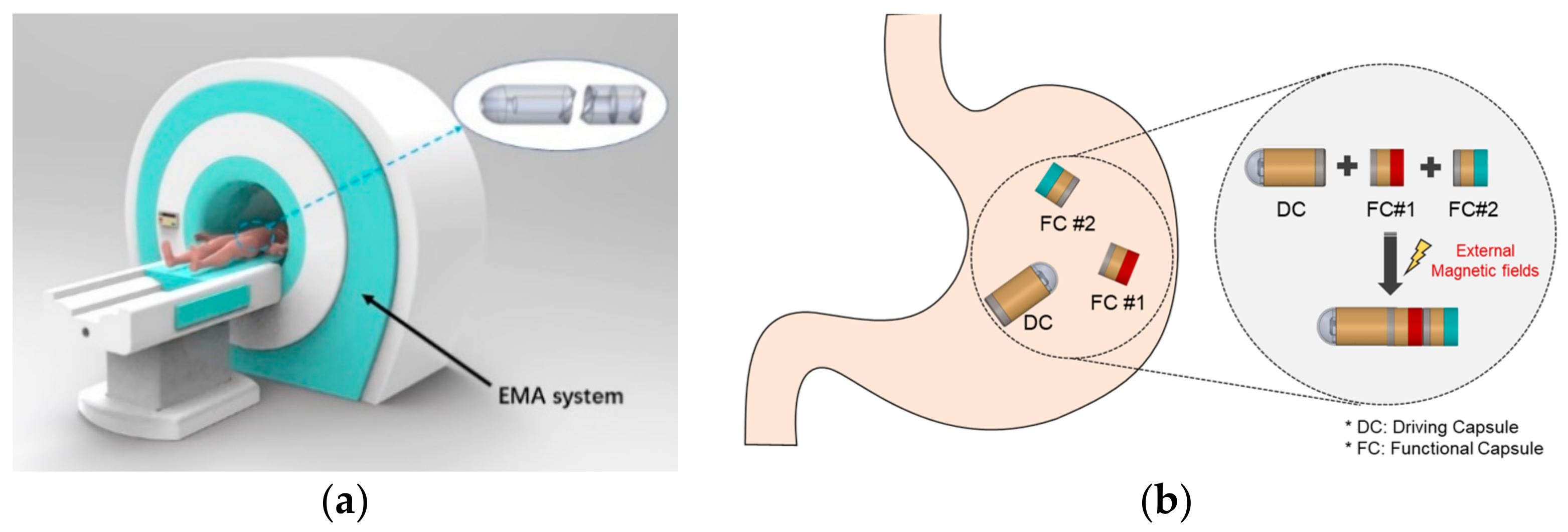
In this paper, we propose a modular capsule system with a novel mechanism for use with multifunctional WCEs. The main concept is to divide a single WCE with multiple integrated functions into several small capsules with individual functions. The patient swallows various small capsules for different functions in sequence, this can significantly reduce the volume of each individual capsule the patient must swallow while retaining multiple functionals. The swallowed modular capsules can be reassembled in the stomach cavity through the external EMA system. Then, utilizing the same EMA system, the assembled modular capsule can be actively moved to the lesion site in order to perform clinical work. After performing the task, the capsules will be disassembled and excreted with the peristalsis of the digestive tract. Figure 1 shows a conceptual overview of the proposed modular capsule system. The modular capsules are divided by role into the driving capsule and several functional capsules. The driving capsule is responsible for the movement and connection of the functional capsules, allowing the functional capsule to be transported to the target lesion in the gastrointestinal tract. There can be one or more functional capsule modules with the module bodies carrying out clinical functions such as biopsy, drug delivery, pH assessment and so on. Based on the modular capsule system proposed, we developed a prototype. In particular, this study focuses on validating the assembly and separation mechanisms of the modular capsule.
The remainder of this paper is organized as follows: Section 2 presents the design of the proposed modular capsule and explains how control of external magnetic fields works. Section 3 describes the evaluation experiments on the proposed modular capsule. Section 4 concludes this paper and provides future directions for related work.
2. Materials and Methods
2.1. Modular Capsule Design
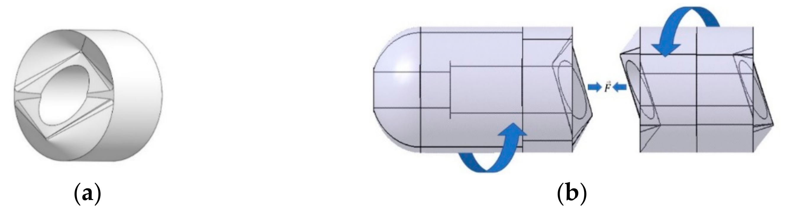
When simply trying to solve the problem of capsule size, it is advisable to make the prototype of the proposed modular capsule system as simple as possible. Therefore, the structure of the prototype is simplified by dividing the modular capsule into two parts: the driving capsule that provides mobility and the functional capsule that would carry the functional components. Specific data on the capsules are shown in Table 2. The diameter of the driving capsule is 10 mm, the length is 20 mm, the diameter of the functional capsule is 10 mm, its length can vary from 12 to 20 mm according to its function. In order to make the capsules align accurately and fixed in a certain direction, when assembling, we designed an asymmetrical three-dimensional structure as the interface surface. As shown in Figure 2, the interface adopts a conical-like curved surface, which automatically rotates until the desired orientation is reached as long as sufficient attractive force is applied between the two modules so that the grooves are completely overlapped. The appearance of the assembled prototype is shown in Figure 3.
2.2. Assembly and Separation Mechanism of the Modular Capsule
The assembly and separation of the modular capsules utilize the magnetization characteristics of soft magnetic materials. A soft magnetic material is a magnetic material with low residual magnetization that can be easily and strongly magnetized even when only a small external magnetic field is applied. The proposed modular capsules contain soft magnetic material inside their bodies, it is possible to easily change the magnetization direction of this soft magnetic material to the desired direction by controlling the external magnetic fields generated by the EMA system. In order to ensure that there is enough attractive force to complete assembly and then move to the desired location, soft magnets with a cylindrical shape were selected. In fact, in terms of controlling the magnetization direction of the soft magnets, a spherical shape that does not need to consider magnetic anisotropy and torque is more suitable. However, although the volume of the magnetic material is an important factor for capsule recombination and locomotion due to the proportional relationship between the volume and magnetic force, it is not easy to increase the volume of a spherical magnet due to the shape’s relatively large footprint compared to its volume. Therefore, spherical magnets are not suitable when striving for miniaturization and do not work well with the kind of interface structure required for modular capsules, as such, cylindrical shape soft magnetic material was chosen.
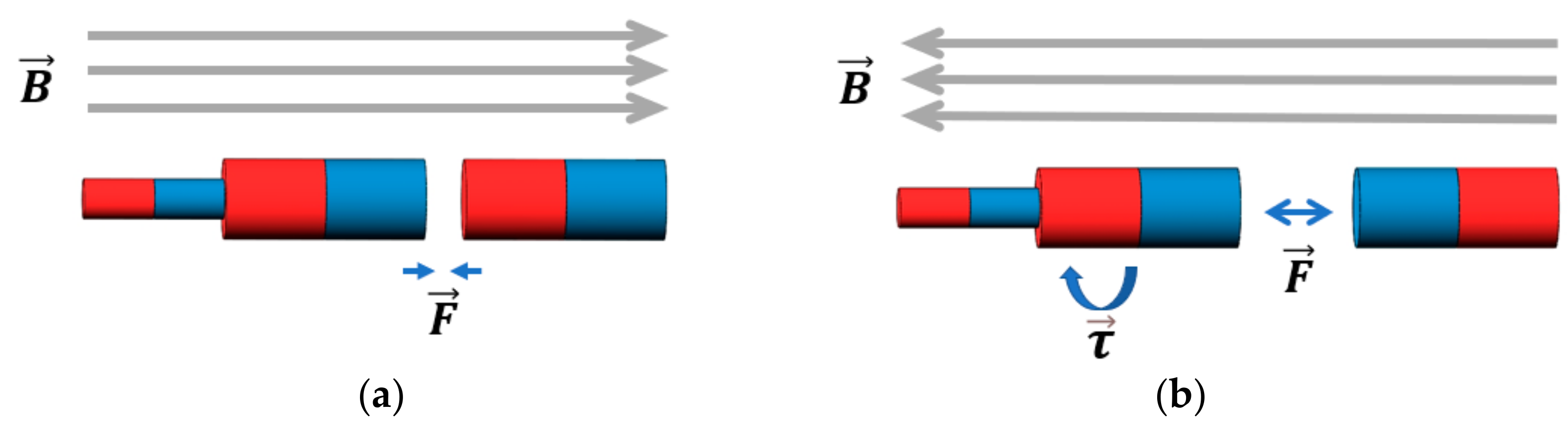
Pure iron is used as the material for the cylindrical soft magnet. Pure iron has high permeability, low coercivity and higher saturation magnetization than other similar soft magnetic materials. For the driving capsule, a combination of a small permanent magnet and soft magnets with cylindrical shapes is used. The purpose of this is to increase the propulsion force when transporting the modular capsules without changing the magnetization direction of the soft magnet in the driving capsule. In contrast, only a cylindrical soft magnet is used in the functional capsule. Due to the anisotropy of the soft magnets, when an external magnetic field is applied, the soft magnet is automatically magnetized along the easy axes. In the case of cylindrical soft magnets, the easy axes can simply be regarded as the long axis of the cylinder [24]. When the direction of the external magnetic field is the same as that of the permanent magnet, the driving capsule and the functional capsule can be magnetized in the same direction and an attractive force to combine the capsules is generated. Meanwhile, when the magnetic field changes to be in the opposite direction, the magnetization direction of the soft magnet in the functional capsule also goes in the opposite direction. However, the magnetization direction of the soft magnet in the driving capsule does not change owing to the presence of the permanent magnet. Thus, the two capsules produce a weak repulsive force between each other, the driving capsule also generates separating torque due to the changes in the external magnetic fields. As a result, the two capsules become separated. Figure 4 shows the magnetization process. In particular, in order to easily control the assembly and separation of the modular capsules, the magnetization direction of the soft magnet within the functional capsule can be easily controlled by external magnetic fields while it is not magnetized by the permanent magnet of the driving capsule. Thus, a small gap of about 1 or 2 mm is set at the intersection between the two soft magnets to prevent contact with each other. Moreover, the higher magnetic permeability of the soft magnet in the driving capsule also creates a magnetic shielding effect, further reducing the impact on the soft magnet of the functional capsule. As a result, when the external magnetic field is set in the opposite direction, the magnetization of the soft magnet in the functional capsule is affected by the external magnetic fields more than it is by the permanent magnet in the driving capsule. Otherwise, if only permanent magnets were used alone as the magnetic material in the driving capsule, they may affect the magnetization of the soft magnet in the functional capsule and thus the separation function may not work properly. This is why a single permanent magnet is not used directly in the driving capsule.
2.3. Control Methods of External Magnetic Fields
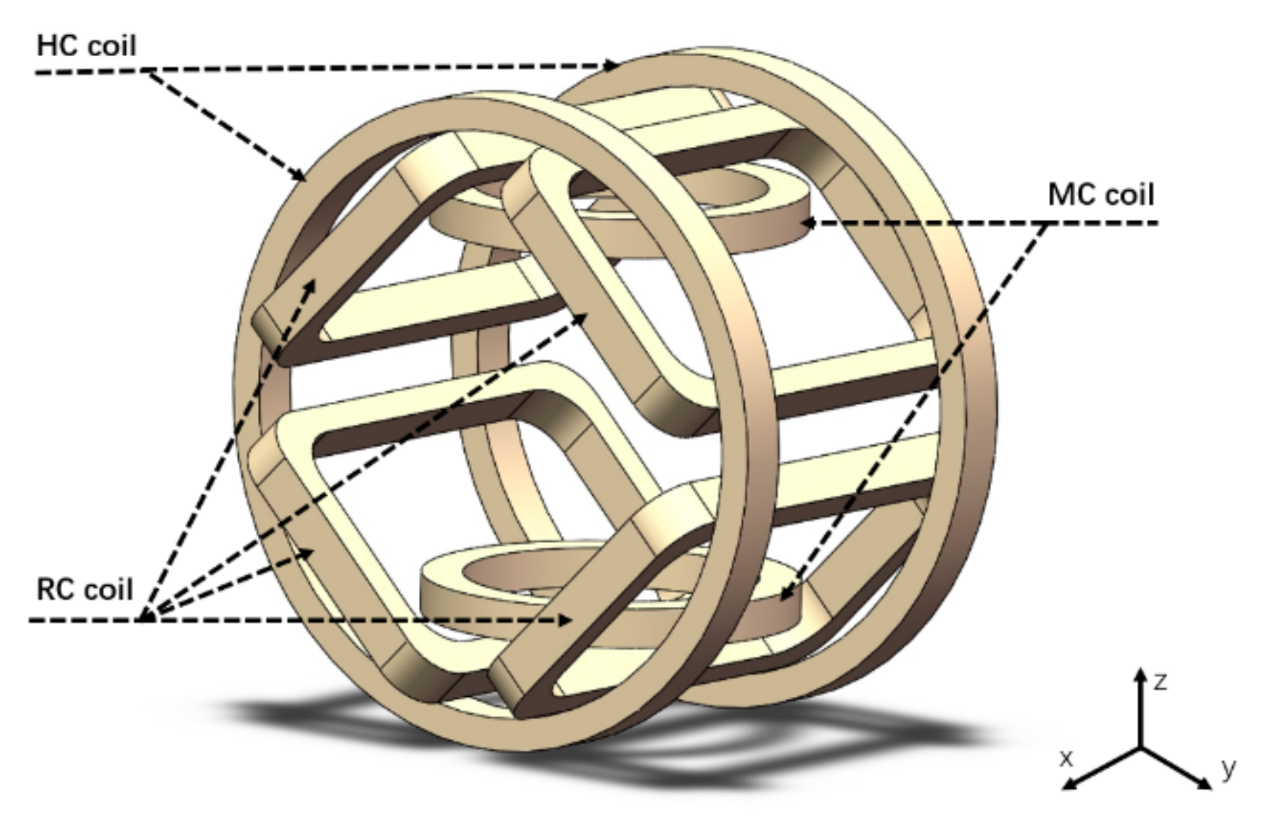
The complex motions for recombination and locomotion of the modular capsules can be well achieved using external magnetic fields controlled by an EMA system [25]. As shown in Figure 5, the EMA system consists of a pair of Helmholtz coils (HC) coils, a pair of Maxwell coils (MC) coils, and two pairs of Rectangular coils (RC) inclined at 45°. Detailed specifications of the coils are shown in Table 3. Compared with conventional pair-coil control, the EMA system uses an independent control algorithm to control the magnetic field allowing greater flexibility. When the direction of the magnetic fields is entered in the LabView control program (NI, Austin, TX, USA), the required current value for each coil is calculated. This is then provided as an input value to the power supply unit (AMETEK, Inc., San Diego, CA, USA) which supplies the currents to each of the eight coils separately. The EMA system can indirectly control the modular capsule by controlling the magnetic field in the region of interest (ROI). The magnetic torque () and force () exerted on the modular capsules placed in the ROI can be expressed as follows:
and
where and are the volume and magnetization of the magnet in the modular capsule, respectively. is a vacuum permeability of and is the magnetic field intensity generated by the EMA system. is the inertia of the modular capsule where q is the base coordinate in Cartesian space. , , and are the gravity of the modular capsule, friction forces in each direction and muscular contraction forces of the organs, respectively. For the phantom experiment, we assumed friction forces [26] with constant property and neglected muscle contraction forces. However, in future animal experiments, friction and muscle contraction caused by physiological movements should be considered. For any point in the ROI, the current required by each coil of the EMA can be expressed by the magnetic field and the driving force [25]:
The magnetization of permanent magnets is a constant, but for soft magnets it is a nonlinear function of the external magnetic field H due to the properties of ferromagnetic materials. The relation for can be written as follows:
The B-H curve of the soft magnet was used to calculate the magnetization and the magnetic force of the magnet in a given magnetic field. Ignoring the mutual influence of the soft magnets between modular capsules, a formula for the approximate force F on the capsules from the external magnetic field can be derived as follows:
where , and are the number of functional modules, the magnetic force of the driving capsule and the functional capsule, respectively. Taking into account Equations (2) and (8), the resultant magnetic force acting on the modular capsules can be calculated as follows:
where and are the total volume of the magnet in the driving capsule and the volume of the single soft magnet in the functional capsule, while and are the average magnetizations of the magnets in the driving capsule and the magnetization of the soft magnet in the functional capsule, respectively.
As it is difficult to directly calculate the magnetization value of the soft magnet in the driving capsule due to the combination of the soft magnet and the permanent magnet in close proximity, a finite element method (FEM) simulation was used for the calculation. The attractive force between the modular capsules was calculated by applying the same formula mentioned above while assuming that any mutual influence is small due to the magnetic shielding effect and the distance between the contact surfaces of the modular capsules.
3. Experiments
3.1. Verification of the Principle of Assembly and Separation Mechanism
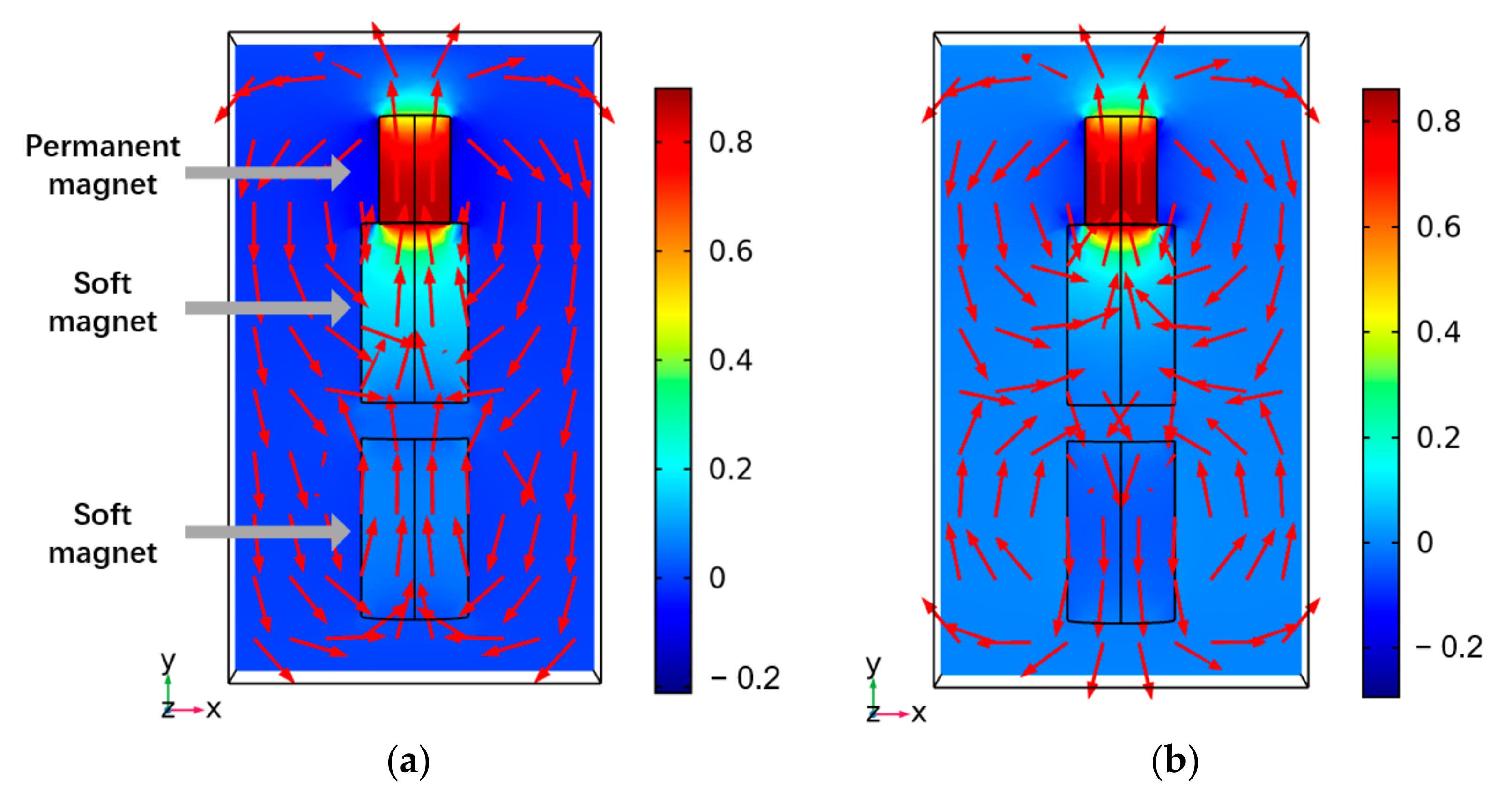
To verify the feasibility of the proposed mechanism for the modular capsules outlined above, FEM simulations using the COMSOL Multiphysics software (COMSOL, Inc., Stockholm, Sweden) were completed and simple experiments were conducted. Figure 6 shows the simulation results for two representative cases of assembly and separation of the modular capsules. The magnetic materials contained in the modular capsules were modeled in 3D with the same shape and size as in the real-world prototype, the material properties of each material in the prototype were applied in the simulation. The small permanent magnet in contact with a larger soft magnet is the magnetic substance in the driving capsule, while the separated soft magnet is the magnetic substance in the functional capsule. In the simulation results, the arrows indicate the direction of the magnetic flux density under a uniform magnetic field of 0.01 T, such as that generated by the EMA system. As shown in Figure 6a, when an external magnetic field is applied in the magnetization direction of the permanent magnet, the magnetization of the driving module and the functional module are the same. Thus, an attractive force is generated between the modular capsules. Whereas, if the external magnetic field is in opposite direction to that of the permanent magnet, the magnetization directions of the driving capsule and the functional capsule are opposite to each other, resulting in a repulsive force.
A simple experiment was performed to look at the assembly and separation of the modular capsules. In particular, we restricted the rotation of the modular capsule to validate that the magnetization direction of the soft magnet is controllable.
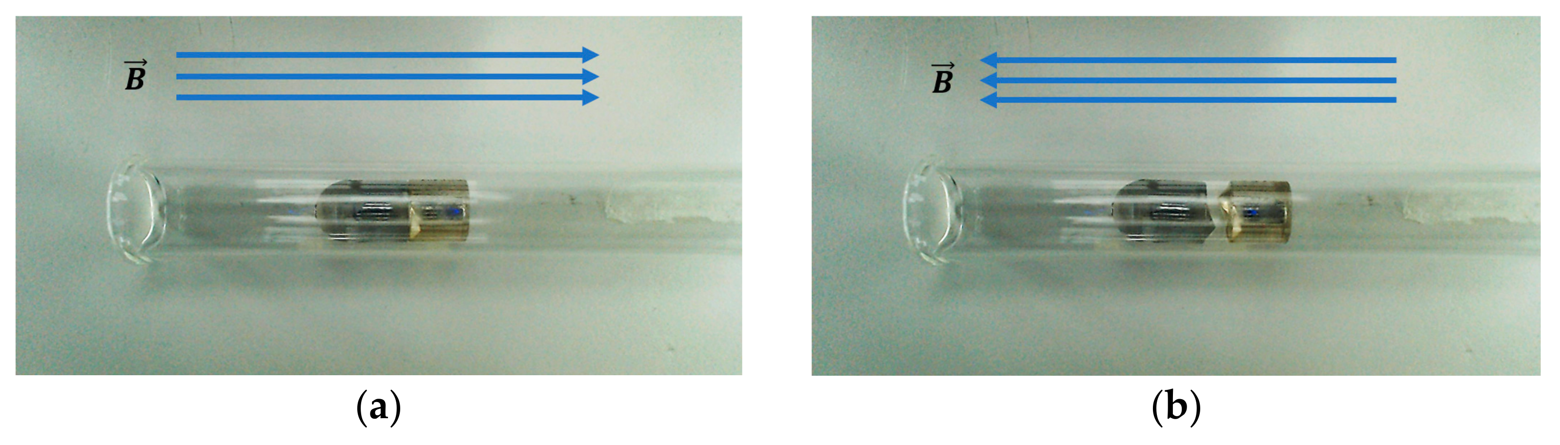
As shown in Figure 7, the prototype modular capsules were placed in a glass tube in the center of an EMA system. Then, an external magnetic field was generated using the EMA system along the magnetization direction of the permanent magnet in the driving capsule. As a result, it can be seen that in Figure 7a the two modules become attached. Then, when the direction of the magnetic fields is reversed, they become separated by the weak repulsive force, as shown in Figure 7b. Through the above simple experiments and FEM simulation, it was verified that the proposed assembly and separation mechanism of the modular capsules can be successfully implemented by controlling the magnetization direction of soft magnetic substances in the functional module. However, no further verification of the repulsive force for separation was conducted, because theoretically, as long as there is no attractive force between the modules, the capsules will gradually separate while the actual repulsive force is too small to be detected.
3.2. Propulsion Force Evaluation
The proposed modular capsule’s motion is designed to be actively controlled for the locomotion and transport of functional modules. Therefore, we measured the propulsion force of the modular capsules driven by the EMA system to verify the feasibility of this kind of propulsion system. Figure 8 presents the configurations and experimental setup for measuring the driving capsule’s and the functional capsule’s propulsion force separately. A load cell (Transducer Techniques, Temecula, CA, USA) was set up and individually connected to the driving capsule and functional capsule via a cable. The modular capsule was placed inside a glass tube and put in the ROI of the EMA system. The propulsion forces were measured with the magnetic gradient field and the magnetic flux density, at various levels.
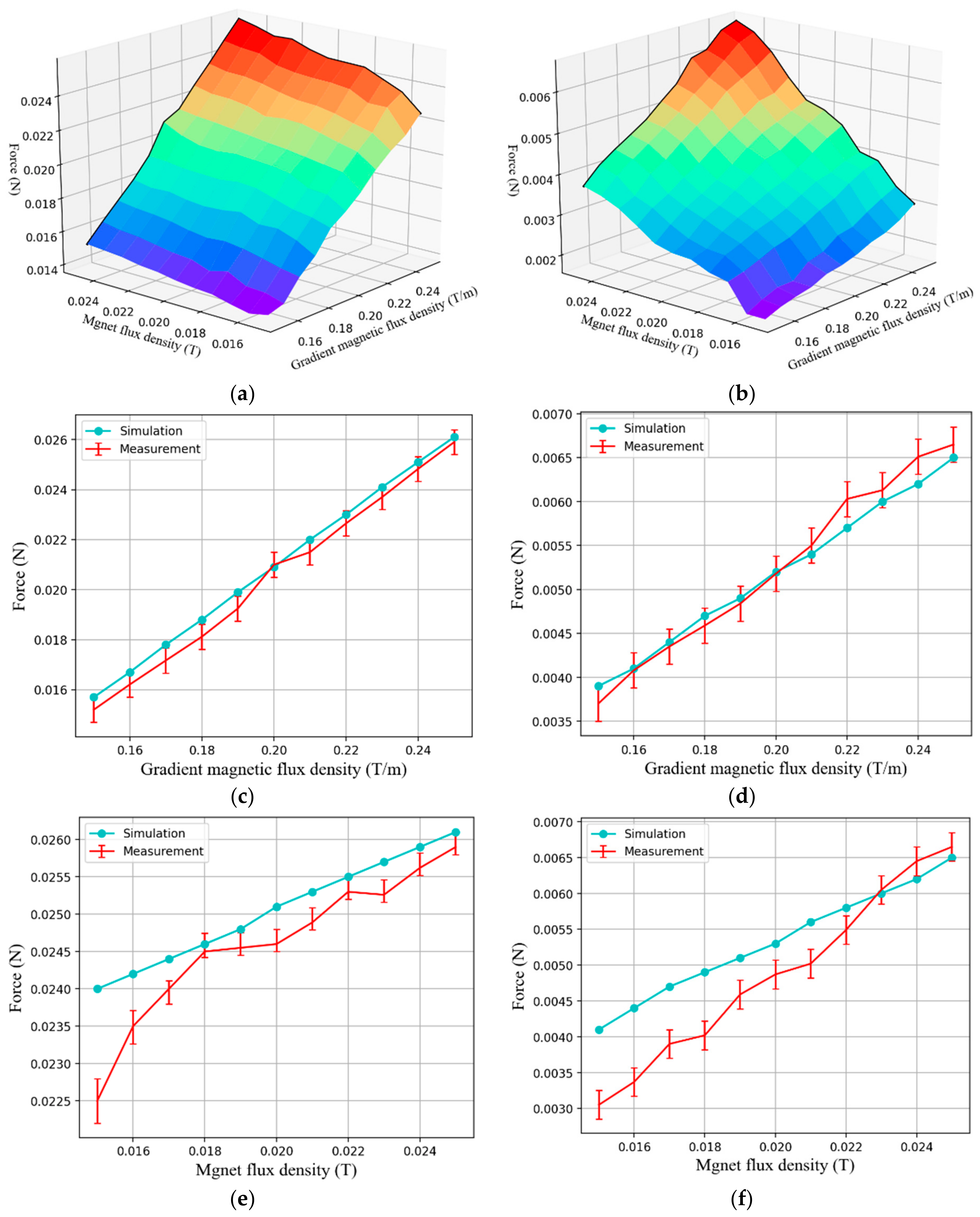
Figure 9 shows the measured forces from the experiment and the FEM simulation results. Looking at the results of the experiment, it can be seen that as the magnetic gradient field and magnetic flux density increase, the driving forces on the driving capsule and the functional capsule also increase, as shown in Figure 9a,b. Specifically, since the magnetization of the functional capsule, which comes solely from the applied magnetic flux density, is much smaller than the magnetization of the driving capsule, the propulsion force of the driving capsule is about 3.7 times greater than that of the functional capsule. During the proposed modular capsules’ assembly process, it is necessary to fix the position of the functional capsule while the driving capsule moves freely. That is, the propulsion force of the functional capsule should be controlled to be less than the frictional force between the functional capsule and the gastrointestinal tract surface. While the propulsion force of the driving capsule should be greater than the resistance against capsule locomotion in the gastrointestinal tract. From related research [26], the propulsion force required to move a capsule weighing 25 mN in the small intestine is about 23 mN, this is close to the maximum propulsion force that can be achieved by the driving capsule. Therefore, it is important to increase the magnetization of the magnetic substance or increase the strength of the external magnetic field for predictable capsule locomotion in a clinical environment. However, the main space in which the assembly process of the modular capsules would occur is in the stomach. If the stomach is filled with water, we can assume that this would significantly reduce friction and flatten the gastric folds to a certain extent. In addition, we believe that the measured propulsion force is sufficient from the viewpoint of verifying the mechanism of the proposed modular capsule system. In the case of the functional capsule, the propulsion force generated by its single soft magnet is relatively small, and its position can be fixed during the assembly process using a small external magnetic field.
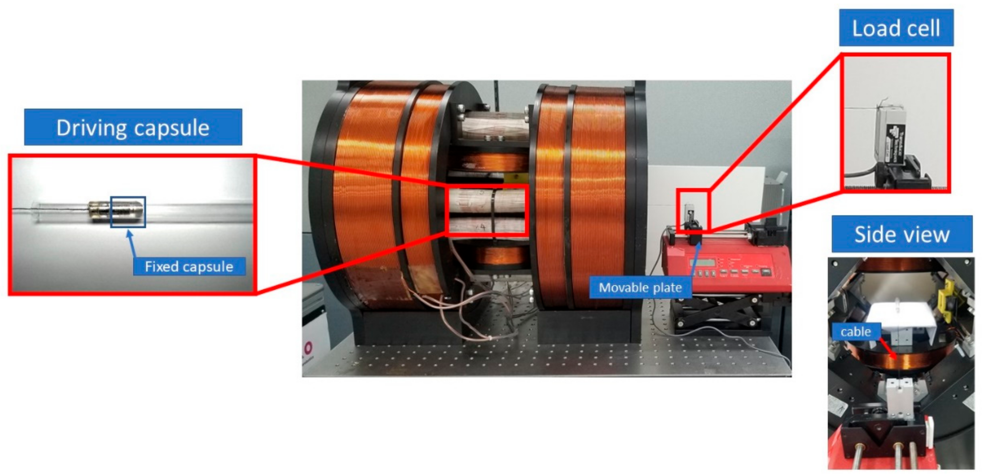
3.3. Attraction Force Evaluation
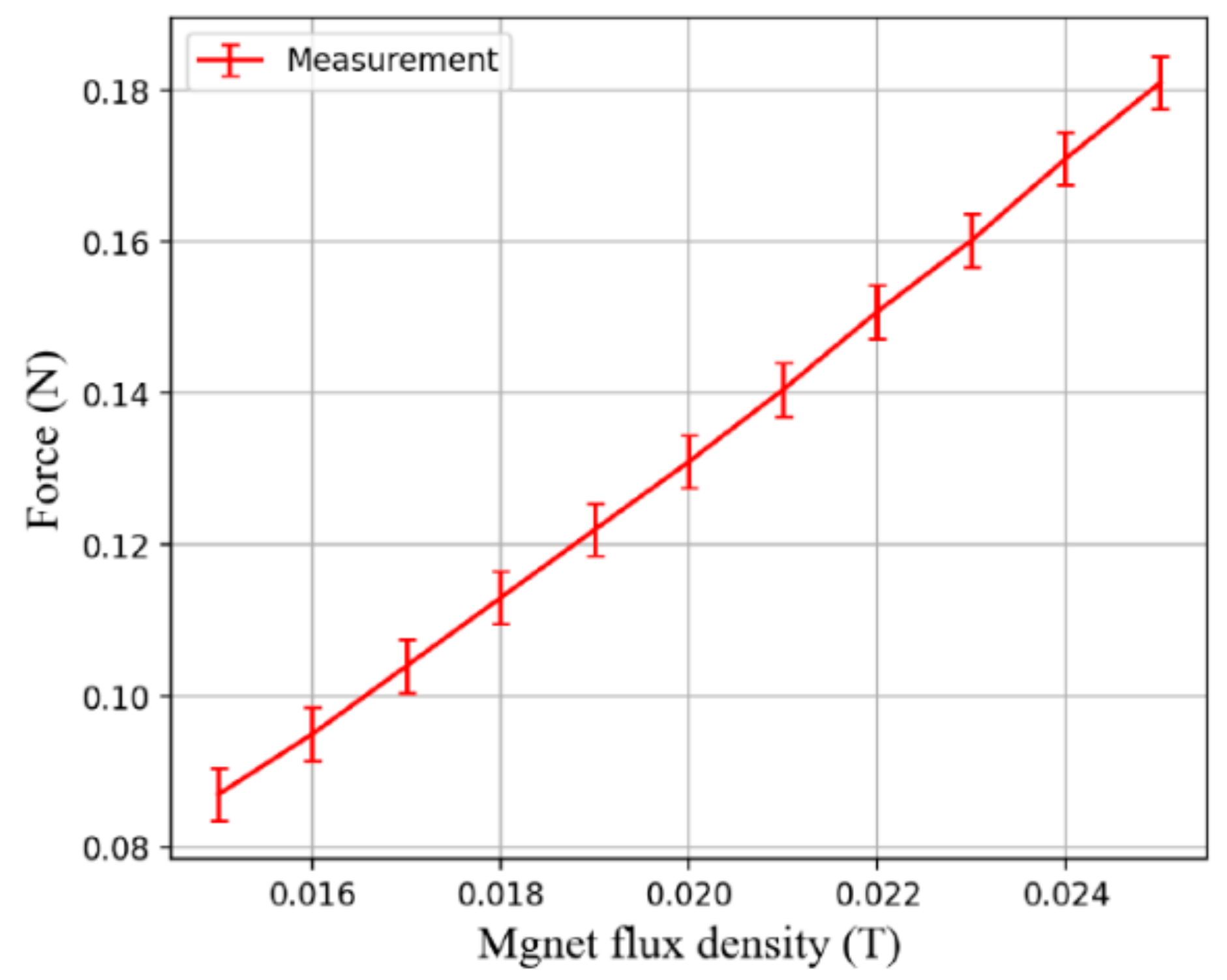
When the EMA system drives the modular capsules, the functional capsule does not completely rely on the traction of the driving capsule. The soft magnet in the functional capsule can also provide a certain driving force, so the required attraction force should be bigger than gastrointestinal tract resistance minus the driving force provided by the functional capsule. Figure 10 shows the experimental setup for measuring the attraction force between the driving capsule and the functional capsule. Since there is no need to move the capsules, only uniform magnetic fluxes of varying strengths from 15 mT to 25 mT are applied to measure the attraction force between modular capsules. As shown in Figure 11, the measured attraction force is proportional to the strength of the magnetic flux density, and the maximum attraction force was approximately 0.18 N at a magnetic flux density of 25 mT. This is sufficiently large to overcome the resistance in the digestive tract, indicating the feasibility of assembly and transport of our modular capsule system.
3.4. In Vitro Validation in a Stomach Phantom
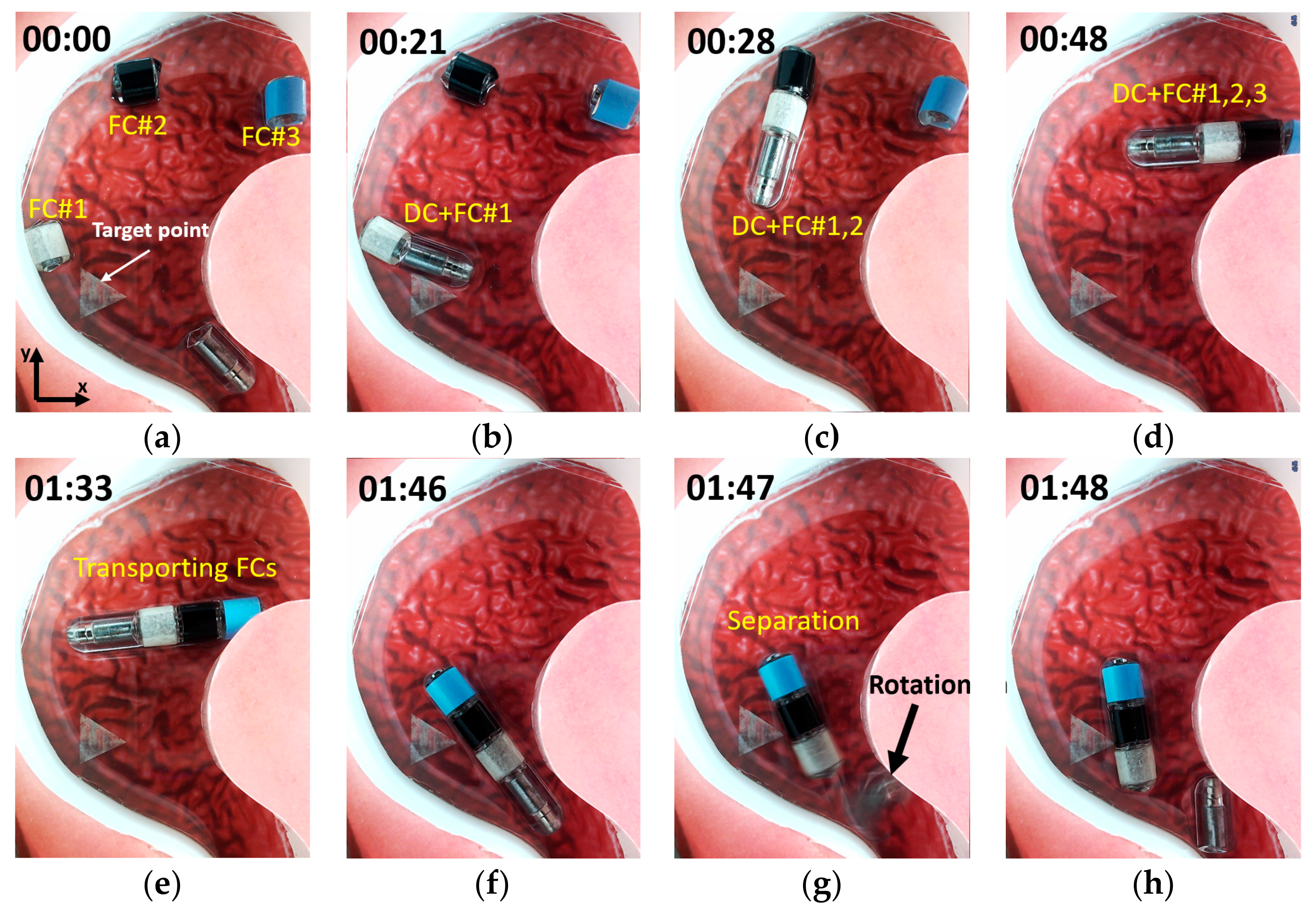
To evaluate the performance of the proposed modular capsules in more realistic circumstances, we conducted experiments using a stomach phantom as described in the following. First, one driving capsule and three functional capsules with different colors were placed in different positions inside the stomach phantom. Then, the driving capsule was driven to assemble with the functional capsules in a specified order. Finally, the assembled capsule modules were separated after moving to a target point. In order to achieve this, we needed to consider two kinds of control conditions. One is when the sum of the propulsion force acting on the driving capsule and the functional capsule should be sufficient to overcome the friction force, and the second is when the propulsion force of a single functional capsule is less than the friction force so that its position is fixed.
By utilizing the characteristics of the soft magnets, we were able to successfully execute the planned scenario while satisfying the control conditions. When moving the driving capsule alone, the external magnetic field was adjusted to try and reduce the strength of the magnetic flux density and to enhance the gradient magnetic field in the ROI. Since the magnetization of the permanent magnet in the driving capsule is fixed, it is possible to selectively generate sufficient propulsion force to move the driving capsule by increasing the gradient magnetic field without the functional capsule moving. After the modular capsules are assembled, we can increase the magnetization of the soft magnet by increasing the strength of the magnetic flux density, which not only increases the attractive force between the modular capsules but also increases the propulsion force of the assembled capsules. Figure 12 shows the experimental result for locomotion, assembly and separation of the modular capsules in a sequence of images. When the driving capsule was moved alone, as shown in Figure 12a, a magnetic flux density of 10mT and a gradient magnetic field of 0.15 T/m were applied. Then, during the assembly and transporting of the functional capsules shown in Figure 12b–f, the applied magnetic flux density and the gradient magnetic fields were 15 mT and 0.15 T/m, respectively. After reaching the target point, the magnetic flux density and magnetic gradient field were applied in such a direction as to separate the modules, as shown in Figure 12g–h.
4. Conclusions
In this study, we proposed a modular capsule system with assembly and separation functions to solve the size problems encountered when trying to add further functional modules to basic WCEs. Our system utilizes the controllable magnetization characteristics of the soft magnetic material inside the modular capsules to achieve assembly and separation controlled by external magnetic fields. Although the modular capsule system proposed in this paper is just an early prototype to verify the mechanism, several advantages were confirmed through the experiments. Processes such as assembly and separation can be achieved using only external magnetic fields, this means that no additional power source is required inside the capsule endoscope. Therefore, the structure of the functional capsule can be very simple, which is very advantageous in terms of the miniaturization of functional capsule endoscopes that patients must swallow.
However, while the proposed mechanism may facilitate miniaturization of capsule endoscopes and lead to them providing multiple functions, the possibilities for their application in clinical practice are still limited. There is a potential safety risk if the separation between the driven capsule and the functional capsule is not smooth enough. In addition, it is not easy to separate each function capsule independently due to the mutual influence of the soft magnets.
In the future work, we will look to optimize the proposed mechanism and improve the prototype of the modular capsule considering 3D models of modular capsules, organ geometry and physicochemical factors of the stomach through testing in animals. Additionally, in animal experiments, the modular capsule system will be tested to ensure its safety as well as assembly and separation mechanism. In particular, since the prototype has not yet been equipped with functional accessories, clinically useful functions will be developed to implement in a multifunctional capsule endoscope. Then, it is planned to establish and validate the clinical methodology for the modular capsule system by reflecting the opinions of clinical experts.
Supplementary Materials
The following are available online at https://0-www-mdpi-com.brum.beds.ac.uk/article/10.3390/act10070159/s1.
Author Contributions
Conceptualization, J.-O.P. and B.K.; methodology, Z.L. and B.K.; software, Z.L. and M.C.H.; validation, Z.L. and M.C.H.; formal analysis, Z.L., C.-S.K. and B.K.; investigation, E.C., D.B. and J.-O.P.; writing—original draft preparation, Z.L.; writing—review and editing, B.K.; visualization, Z.L.; supervision, C.-S.K., J.-O.P. and B.K.; funding acquisition, J.-O.P. All authors have read and agreed to the published version of the manuscript.
Funding
This research was supported by the grant of the Korea Health Technology R&D Project through the Korea Health Industry Development Institute (KHIDI), funded by the Ministry of Health and Welfare, Republic of Korea (grant number: HI19C0642).
Conflicts of Interest
The authors declare no conflict of interest.
References
- Iddan, G.; Meron, G.; Glukhovsky, A.; Swain, P. Wireless capsule endoscopy. Nature 2000, 405, 417. [Google Scholar] [CrossRef]
- Sendoh, M.; Ishiyama, K.; Arai, K.I. Fabrication of magnetic actuator for use in capsule endoscope. IEEE Trans. Magnetics 2003, 39, 3232–3234. [Google Scholar] [CrossRef]
- Chiba, A.; Sendoh, M.; Ishiyama, K.; Arai, K.I.; Kawano, H.; Uchiyama, A.; Takizawa, H. Magnetic Actuator for a Capsule Endoscope Navigation System. J. Magn. 2007, 12, 89–92. [Google Scholar] [CrossRef]
- Morita, E.; Ohtsuka, N.; Shindo, Y.; Nouda, S.; Kuramoto, T.; Inoue, T.; Murano, M.; Umegaki, E.; Higuchi, K. In vivo trial of a driving system for a self-propelling capsule endoscope using a magnetic field (with video). Gastrointest. Endosc. 2010, 72, 836–840. [Google Scholar] [CrossRef] [PubMed]
- Kósa, G.; Jakab, P.; Jolesz, F.; Hata, N. Swimming capsule endoscope using static and RF magnetic field of MRI for propulsion. In Proceedings of the 2008 IEEE International Conference on Robotics and Automation; Institute of Electrical and Electronics Engineers, Pasadena, CA, USA, 19–23 May 2008; pp. 2922–2927. [Google Scholar]
- Nam, S.-J.; Lee, H.S.; Lim, Y.J. Evaluation of Gastric Disease with Capsule Endoscopy. Clin. Endosc. 2018, 51, 323–328. [Google Scholar] [CrossRef] [PubMed] [Green Version]
- Liao, Z.; Hou, X.; Lin-Hu, E.-Q.; Sheng, J.-Q.; Ge, Z.-Z.; Jiang, B.; Hou, X.-H.; Liu, J.-Y.; Li, Z.; Huang, Q.-Y.; et al. Accuracy of Magnetically Controlled Capsule Endoscopy, Compared With Conventional Gastroscopy, in Detection of Gastric Diseases. Clin. Gastroenterol. Hepatol. 2016, 14, 1266–1273. [Google Scholar] [CrossRef] [PubMed] [Green Version]
- Denzer, U.W.; Rösch, T.; Hoytat, B.; Abdel-Hamid, M.; Hebuterne, X.; Vanbiervielt, G.; Filippi, J.; Ogata, H.; Hosoe, N.; Ohtsuka, K.; et al. Magnetically Guided Capsule Versus Conventional Gastroscopy for Upper Abdominal Complaints. J. Clin. Gastroenterol. 2015, 49, 101–107. [Google Scholar] [CrossRef] [PubMed]
- Pandolfino, J.; Pandolfino, J.E.; Richter, J.E.; Ours, T.; Guardino, J.M.; Chapman, J.; Kahrilas, P.J. Ambulatory esophageal pH monitoring using a wireless system. Am. J. Gastroenterol. 2003, 98, 740–749. [Google Scholar] [CrossRef]
- Woods, S.P.; Constandinou, T.G. Wireless capsule endoscope for targeted drug delivery: Mechanics and design considerations. IEEE Trans. Biomed. Eng. 2013, 60, 945–953. [Google Scholar] [CrossRef] [Green Version]
- Hoang, M.C.; Le, V.H.; Kim, J.; Choi, E.; Kang, B.; Park, J.-O.; Kim, C.-S. A wireless tattooing capsule endoscope using external electromagnetic actuation and chemical reaction pressure. PLoS ONE 2019, 14, e0219740. [Google Scholar] [CrossRef] [Green Version]
- Hoang, M.C.; Le, V.H.; Kim, J.; Choi, E.; Kang, B.; Park, J.-O.; Kim, C.-S. Untethered Robotic Motion and Rotating Blade Mechanism for Actively Locomotive Biopsy Capsule Endoscope. IEEE Access 2019, 7, 93364–93374. [Google Scholar] [CrossRef]
- Hoang, M.C.; Le, V.H.; Nguyen, K.T.; Du Nguyen, V.; Kim, J.; Choi, E.; Bang, S.; Kang, B.; Park, J.-O.; Kim, C.-S. A Robotic Biopsy Endoscope with Magnetic 5-DOF Locomotion and a Retractable Biopsy Punch. Micromachines 2020, 11, 98. [Google Scholar] [CrossRef] [Green Version]
- Yim, S.; Gultepe, E.; Gracias, D.H.; Sitti, M. Biopsy using a Magnetic Capsule Endoscope Carrying, Releasing, and Retrieving Untethered Microgrippers. IEEE Trans. Biomed. Eng. 2014, 61, 513–521. [Google Scholar] [CrossRef] [Green Version]
- Do, T.N.; Seah, T.E.T.; Yu, H.K.; Phee, S.J. Development and Testing of a Magnetically Actuated Capsule Endoscopy for Obesity Treatment. PLoS ONE 2016, 11, e0148035. [Google Scholar] [CrossRef]
- Le, V.H.; Leon-Rodriguez, H.; Lee, C.; Go, G.; Zhen, J.; Du Nguyen, V.; Choi, H.; Ko, S.Y.; Park, J.-O.; Park, S. A soft-magnet-based drug-delivery module for active locomotive intestinal capsule endoscopy using an electromagnetic actuation system. Sensors Actuators A Phys. 2016, 243, 81–89. [Google Scholar] [CrossRef]
- Nguyen, K.T.; Hoang, M.C.; Choi, E.; Kang, B.; Park, J.-O.; Kim, C.-S. Medical Microrobot—A Drug Delivery Capsule Endoscope with Active Locomotion and Drug Release Mechanism: Proof of Concept. Int. J. Control. Autom. Syst. 2019, 18, 65–75. [Google Scholar] [CrossRef]
- Rondonotti, E.; Herrerias, J.M.; Pennazio, M.; Caunedo, A.; Mascarenhas-Saraiva, M.; de Franchis, R. Complications, limitations, and failures of capsule endoscopy: A review of 733 cases. Gastrointest. Endosc. 2005, 62, 712–716. [Google Scholar] [CrossRef]
- Guo, J.; Liu, P.; Guo, S.; Wang, L.; Sun, G. Development of a novel wireless spiral capsule robot with modular structure. In Proceedings of the 2017 IEEE International Conference on Mechatronics and Automation (ICMA), Takamatsu, Japan, 6–9 August 2017; pp. 439–444. [Google Scholar] [CrossRef]
- Kim, L.; Tang, S.C.; Yoo, S.-S. Prototype modular capsule robots for capsule endoscopies. In Proceedings of the 2013 13th International Conference on Control, Automation and Systems (ICCAS 2013), Gwangju, Korea, 20–23 October 2013; pp. 350–354. [Google Scholar] [CrossRef]
- Nagy, Z.; Fluckiger, M.; Oung, R.; Kaliakatsos, I.K.; Hawkes, E.W.; Nelson, B.J.; Harada, K.; Susilo, E.; Menciassi, A.; Dario, P.; et al. Assembling reconfigurable endoluminal surgical systems: Opportunities and challenges. Int. J. Biomechatronics Biomed. Robot. 2009, 1, 3. [Google Scholar] [CrossRef]
- Harada, K.; Oetomo, D.; Susilo, E.; Menciassi, A.; Daney, D.; Merlet, J.-P.; Dario, P. A reconfigurable modular robotic endoluminal surgical system: Vision and preliminary results. Robot. 2009, 28, 171–183. [Google Scholar] [CrossRef] [Green Version]
- Yoo, S.-S.; Rama, S.; Szewczyk, B.; Pui, J.W.; Lee, W.; Kim, L. Endoscopic capsule robots using reconfigurable modular assembly: A pilot study. Int. J. Imaging Syst. Technol. 2014, 24, 359–365. [Google Scholar] [CrossRef]
- Hoselitz, K. Modern Magnetic Materials. Phys. Bull. 1962, 13, 107–112. [Google Scholar] [CrossRef]
- Hoang, M.C.; Nguyen, K.T.; Le, V.H.; Kim, J.; Choi, E.; Kang, B.; Park, J.-O.; Kim, C.-S. Independent Electromagnetic Field Control for Practical Approach to Actively Locomotive Wireless Capsule Endoscope. IEEE Trans. Syst. Man. Cybern. Syst. 2019, 51, 3040–3052. [Google Scholar] [CrossRef]
- Kim, J.-S.; Sung, I.-H.; Kim, Y.-T.; Kwon, E.-Y.; Kim, D.-E.; Jang, Y.H. Experimental investigation of frictional and viscoelastic properties of intestine for microendoscope application. Tribol. Lett. 2006, 22, 143–149. [Google Scholar] [CrossRef]
Figure 1.
(a) Overview of the proposed modular capsule system [13]. (b) Recombination mechanism of the modular capsules.
Figure 1.
(a) Overview of the proposed modular capsule system [13]. (b) Recombination mechanism of the modular capsules.

Figure 2.
Schematic of the modular capsules: (a) Surface design with asymmetric interlocking interface. (b) Assembly mechanism of the modular capsules.
Figure 2.
Schematic of the modular capsules: (a) Surface design with asymmetric interlocking interface. (b) Assembly mechanism of the modular capsules.

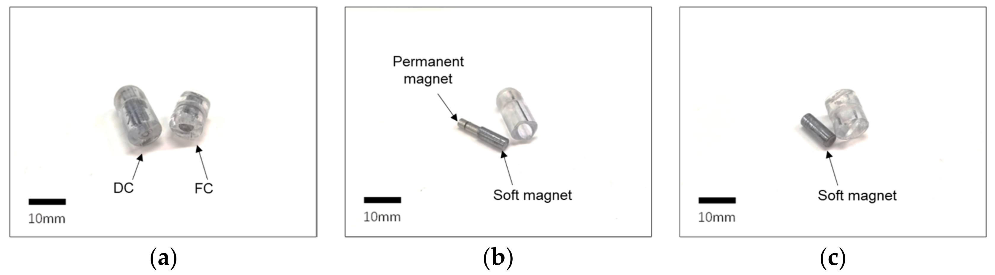
Figure 3.
(a) Prototype of modular capsules. (b) The driving capsule (DC) showing the combination of the permanent magnet and soft magnet inside. (c) The functional capsule (FC) with the soft magnet.
Figure 3.
(a) Prototype of modular capsules. (b) The driving capsule (DC) showing the combination of the permanent magnet and soft magnet inside. (c) The functional capsule (FC) with the soft magnet.

Figure 4.
Principles behind the assembly and separation functions. (a) Assembly function: when the external magnetic field direction is the same as the magnetization direction of the permanent magnet, an attractive force is generated between modules. (b) Separation function: when the external magnetic field is in the opposite direction to the magnetization direction of the permanent magnet, there is a repulsive force between the modules, and torque on the permanent magnet is generated.

Figure 5.
Schematic of the EMA system for the control of the proposed modular capsules.

Figure 6.
Simulation results looking at the assembly and separation of capsules. (a) The direction of the external magnetic field is the same as that of the permanent magnet. (b) The direction of the external magnetic field is opposite to that of the permanent magnet.
Figure 6.
Simulation results looking at the assembly and separation of capsules. (a) The direction of the external magnetic field is the same as that of the permanent magnet. (b) The direction of the external magnetic field is opposite to that of the permanent magnet.

Figure 7.
Experiment testing assembly by attractive force and separation by weak repulsive force. (a) Assembly by attractive force: the direction of the external magnetic field is the same as that of the permanent magnet. (b) Separation by weak repulsive force: the direction of the external magnetic field is opposite to that of the permanent magnet.

Figure 8.
Experimental setup for measuring propulsion force.

Figure 9.
Result of propulsion force measurements. Measured propulsion force of the driving capsule (a), and functional capsule (b). Relationship between the propulsion force and gradient magnetic field under a fixed magnetic flux density for the driving capsule (c), and for the functional capsule (d). Relation between the propulsion force and magnetic flux density under a fixed gradient magnetic field for the driving capsule (e), and for the functional capsule (f).

Figure 10.
Experimental setup for measuring attraction force.

Figure 11.
Measured attraction force between the modular capsules.

Figure 12.
Experiment using stomach phantom. (a) Driving capsule locomotion. (b–f) Assembly and transporting of the functional capsules. (g,h) Separation motion of the modular capsules. A related video is provided in the Supplementary Materials.
Figure 12.
Experiment using stomach phantom. (a) Driving capsule locomotion. (b–f) Assembly and transporting of the functional capsules. (g,h) Separation motion of the modular capsules. A related video is provided in the Supplementary Materials.


Table 1.
Comparison of modular capsule endoscopes.
| Year, [Ref.] | Assembly/Separation Method | Size (Diameter × Length) | Control/Actuation Method | Advantage | Limitation |
|---|---|---|---|---|---|
| 2009 [21] | Permanent magnets/Motor | 15.4 mm 36.5 mm | External remote control/Motor | High controllability and DOF | Energy consumption |
| 2010 [22] | Permanent magnets/Motor | 13 mm 23 mm | External remote control/Motor | High controllability and DOF | Energy consumption |
| 2013 [20] | Permanent magnets/Motor | 32 mm mm | External remote control/Motor | Wireless power transmission | Energy consumption, Large volume, Low DOF, |
| 2014 [23] | Permanent magnets/Motor | 32 mm 88 mm, 40 mm mm | External remote control/Motor | High controllability and DOF | Energy consumption Large volume |
| 2017 [19] | Permanent magnets/Magnetic field | 12.5 mm 39.4 mm 12.5 mm 33.8 mm | Magnet field control and Magnet field actuation | No energy consumption | Low DOF |
| Proposed | Soft magnets/Magnetic field | 10 mm 12~20 mm 10 mm 20 mm | Magnet field control and Magnet field actuation | No energy consumption, High controllability and DOF | Difficult to install the functional component |
Table 2.
Specification of the modular capsules.
| Parts | DC Shell | DC Magnets (Soft, Permanent) | FC Shell | FC Magnet |
|---|---|---|---|---|
| Radius (mm) | 5 | 2, 1.5 | 5 | 2 |
| Length (mm) | 20 | 10, 7 | 12 | 10 |
| Total weight (g) | 2.41 | 1.56 |
Table 3.
Specification of the coils in the EMA system.
| Coils | HC-Coil | MC-Coil | RC-Coil |
|---|---|---|---|
| Radius (mm) | 195 | 100 | n/a |
| Width Length (mm) | n/a | n/a | 156 337 |
| Distance (mm) | 195 | 173.2 | 200 |
| Number of turns | 710 | 660 | 600 |
Publisher’s Note: MDPI stays neutral with regard to jurisdictional claims in published maps and institutional affiliations. |
© 2021 by the authors. Licensee MDPI, Basel, Switzerland. This article is an open access article distributed under the terms and conditions of the Creative Commons Attribution (CC BY) license (https://creativecommons.org/licenses/by/4.0/).
Share and Cite
MDPI and ACS Style
Li, Z.; Hoang, M.C.; Kim, C.-S.; Choi, E.; Bang, D.; Park, J.-O.; Kang, B. Modular Capsules with Assembly and Separation Mechanism: Proof of Concept. Actuators 2021, 10, 159. https://0-doi-org.brum.beds.ac.uk/10.3390/act10070159
AMA Style
Li Z, Hoang MC, Kim C-S, Choi E, Bang D, Park J-O, Kang B. Modular Capsules with Assembly and Separation Mechanism: Proof of Concept. Actuators. 2021; 10(7):159. https://0-doi-org.brum.beds.ac.uk/10.3390/act10070159
Chicago/Turabian StyleLi, Zhenyu, Manh Cuong Hoang, Chang-Sei Kim, Eunpyo Choi, Doyeon Bang, Jong-Oh Park, and Byungjeon Kang. 2021. "Modular Capsules with Assembly and Separation Mechanism: Proof of Concept" Actuators 10, no. 7: 159. https://0-doi-org.brum.beds.ac.uk/10.3390/act10070159
Note that from the first issue of 2016, this journal uses article numbers instead of page numbers. See further details here.