
Performance Assessment of an Electric Power Steering System for Driverless Formula Student Vehicles

 ,
,  , and
, and
Abstract
:1. Introduction
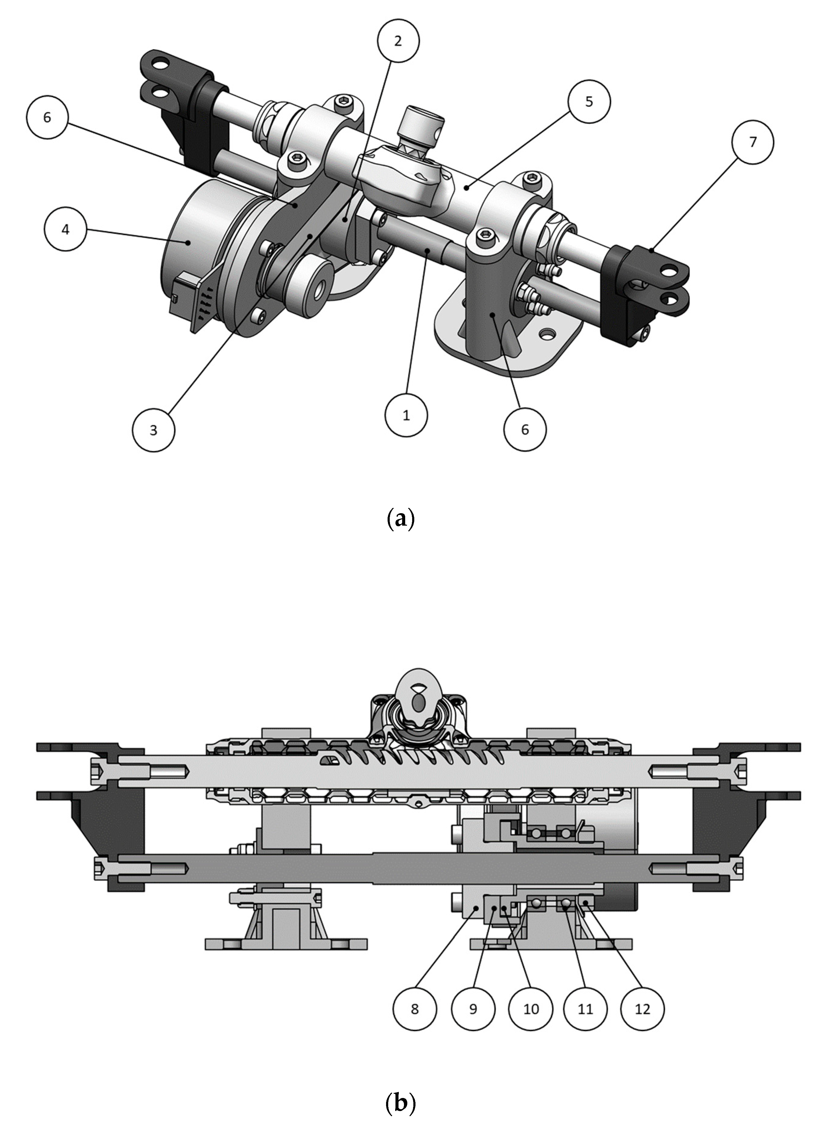
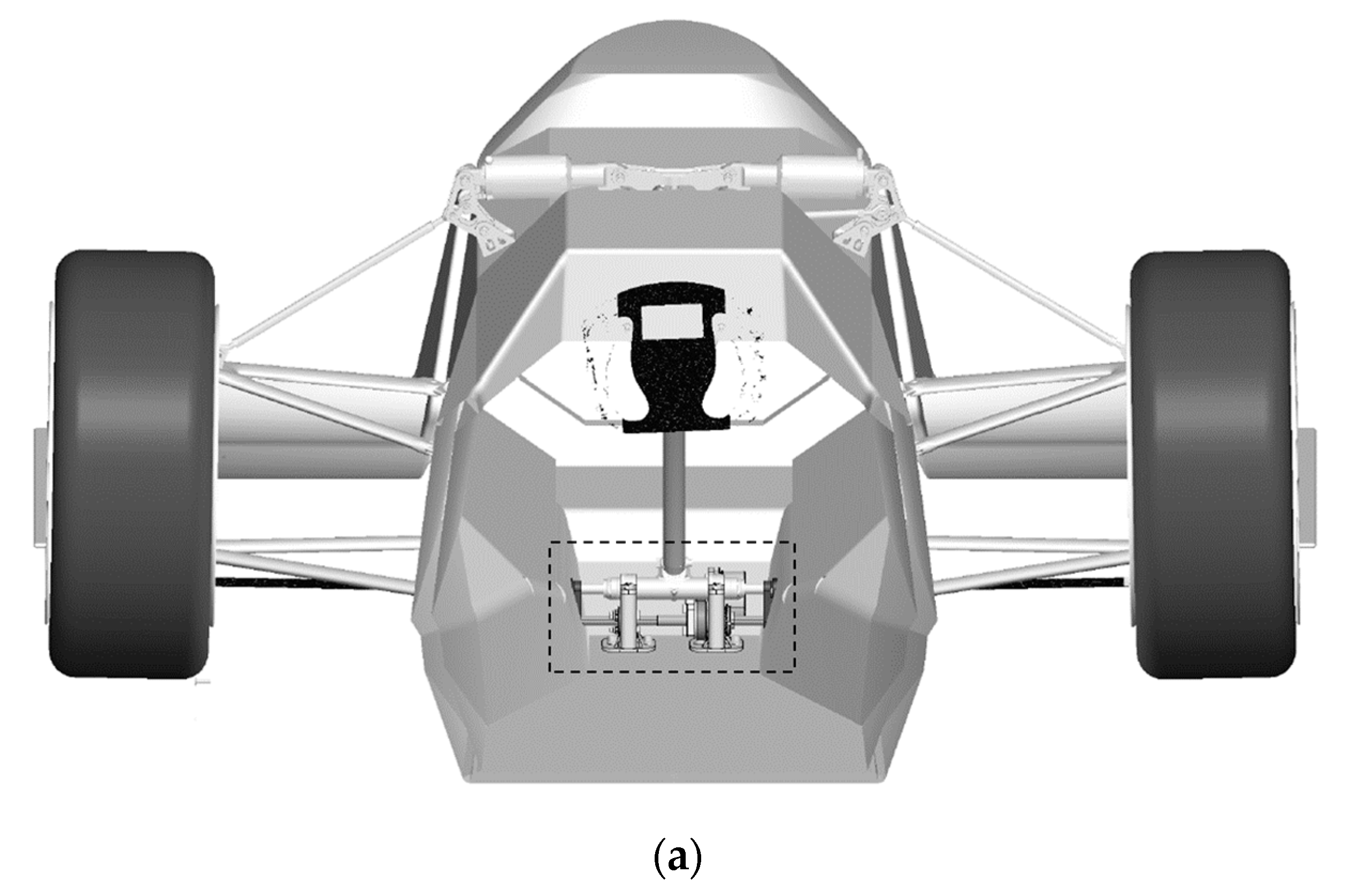
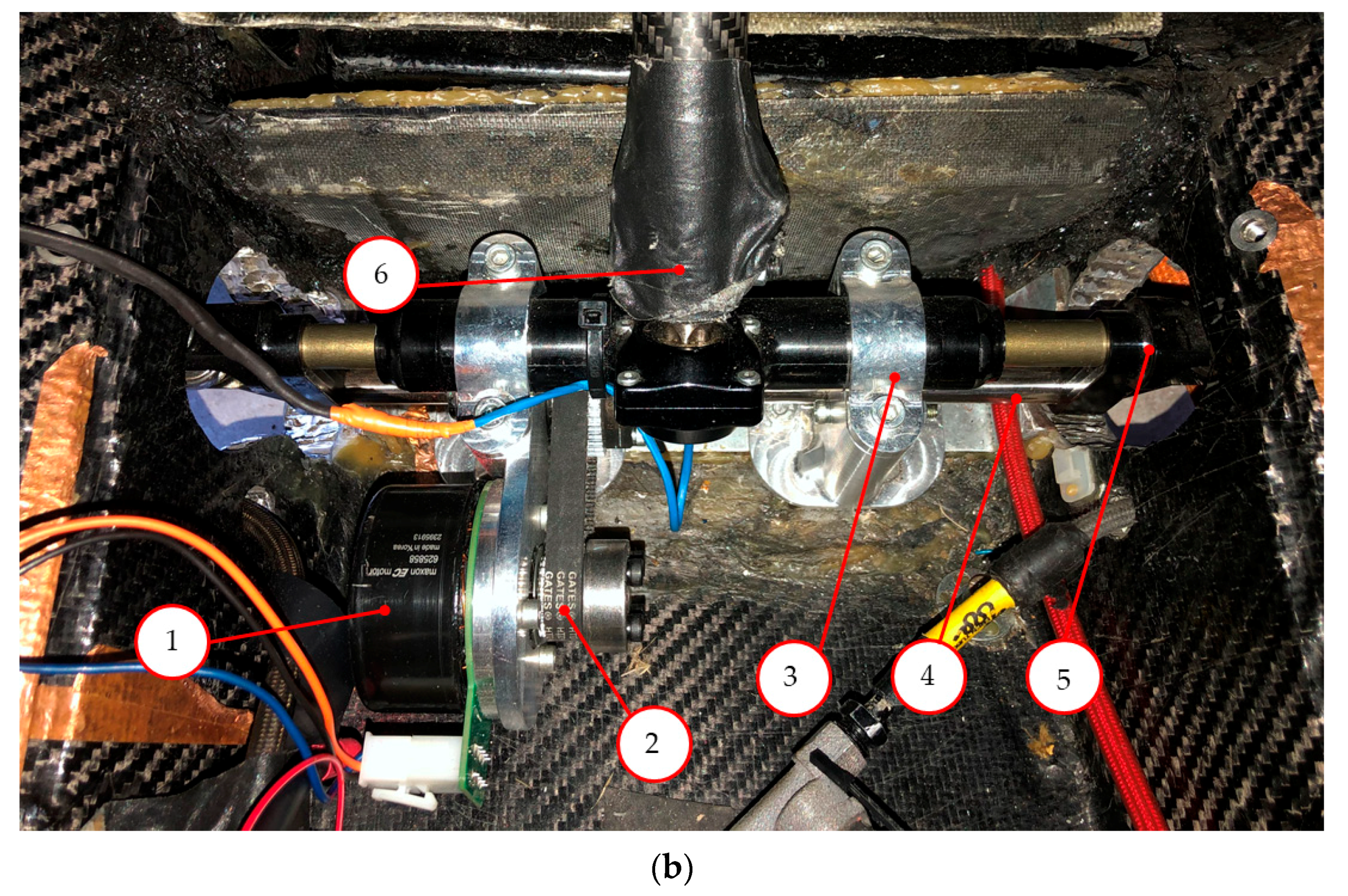
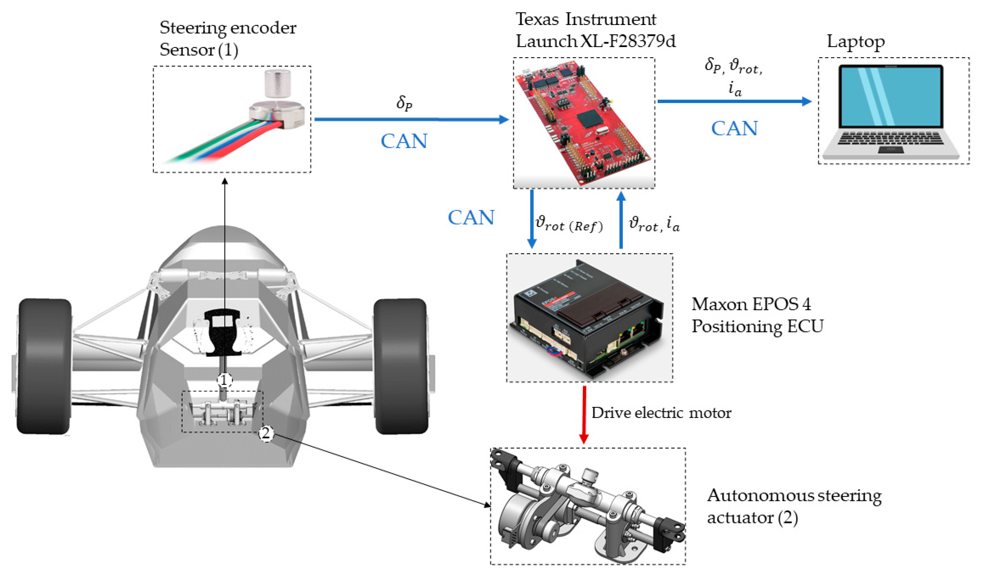
2. System Layout
- Small rack assembly with a rack length equal to 264 mm.
- Required total rack travel equal to 45 mm, by considering a steering wheel working angle from −90 to +90 degrees.
- Required actuation speed , by taking as target the capability of the driver to actuate the steering wheel from full left to full right in 1 s.
- Reversibility between driverless and with-driver modes must be guaranteed without mechanically dismounting any physical part, according to the competition rules [21].
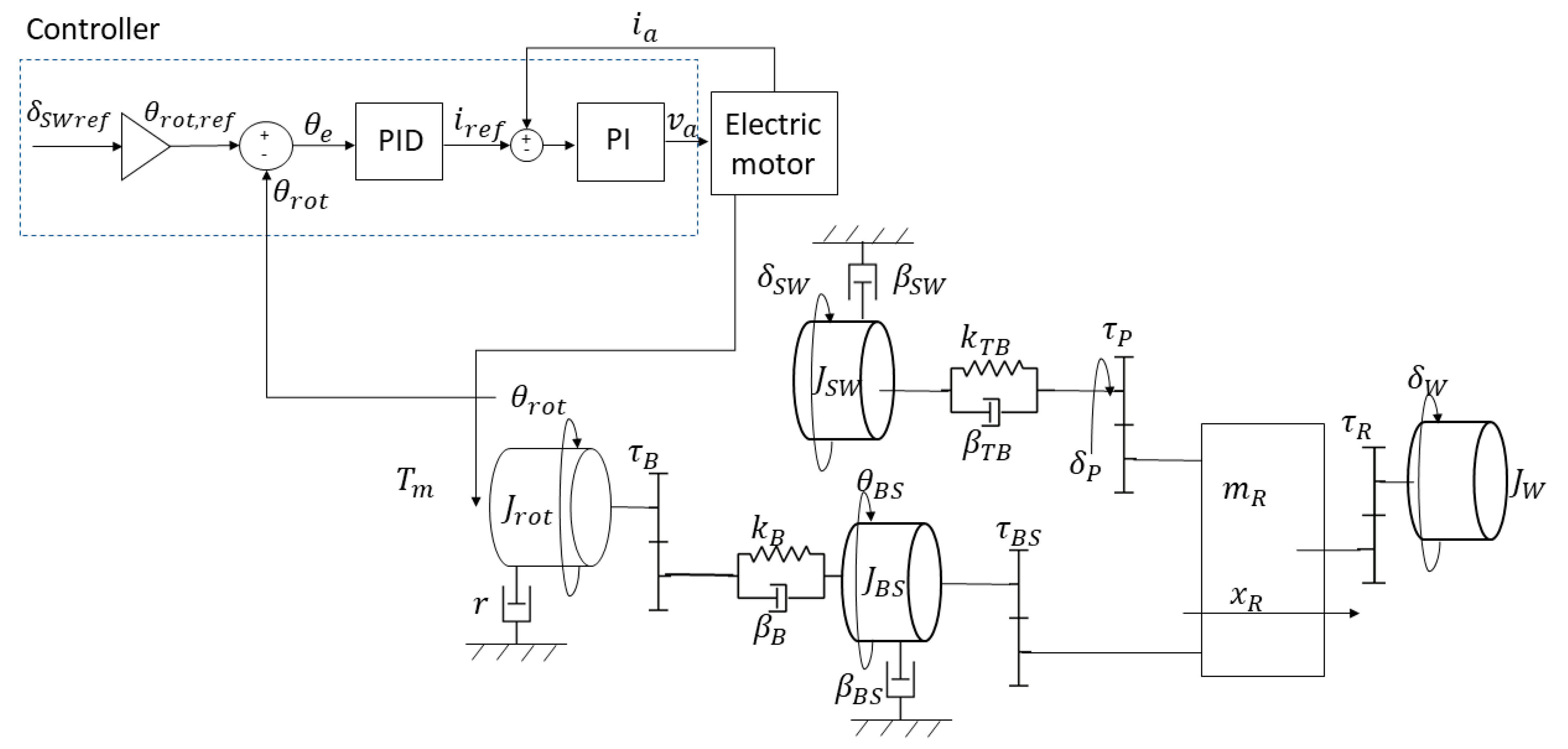
3. System Modelling
3.1. Electric Motor
3.2. Mechanical System
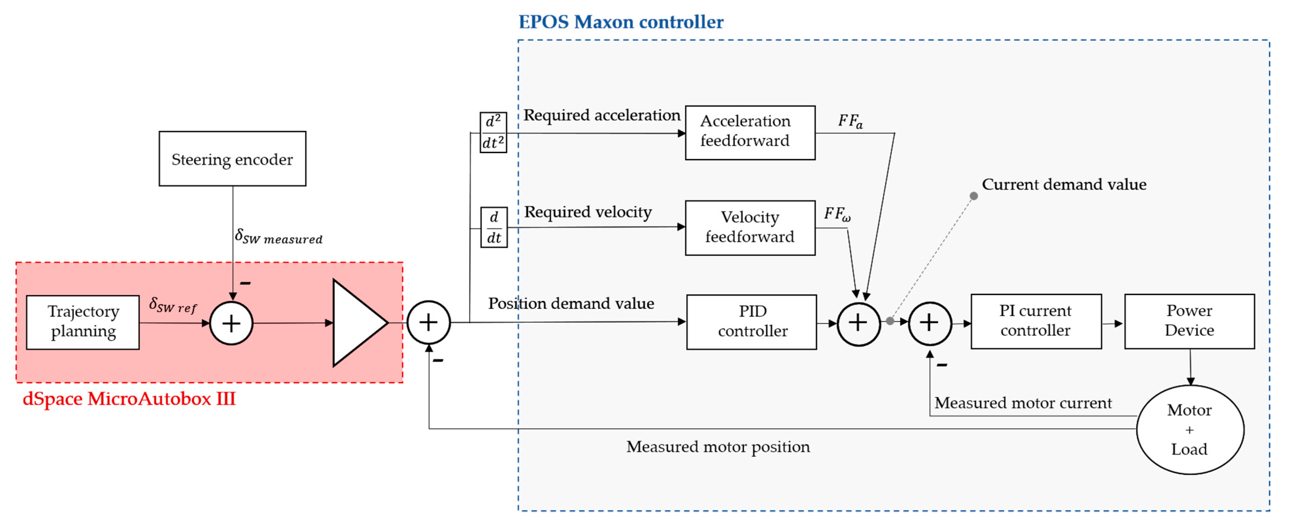
3.3. Electric Motor Control
4. Results and Discussion
4.1. Testbed Setup
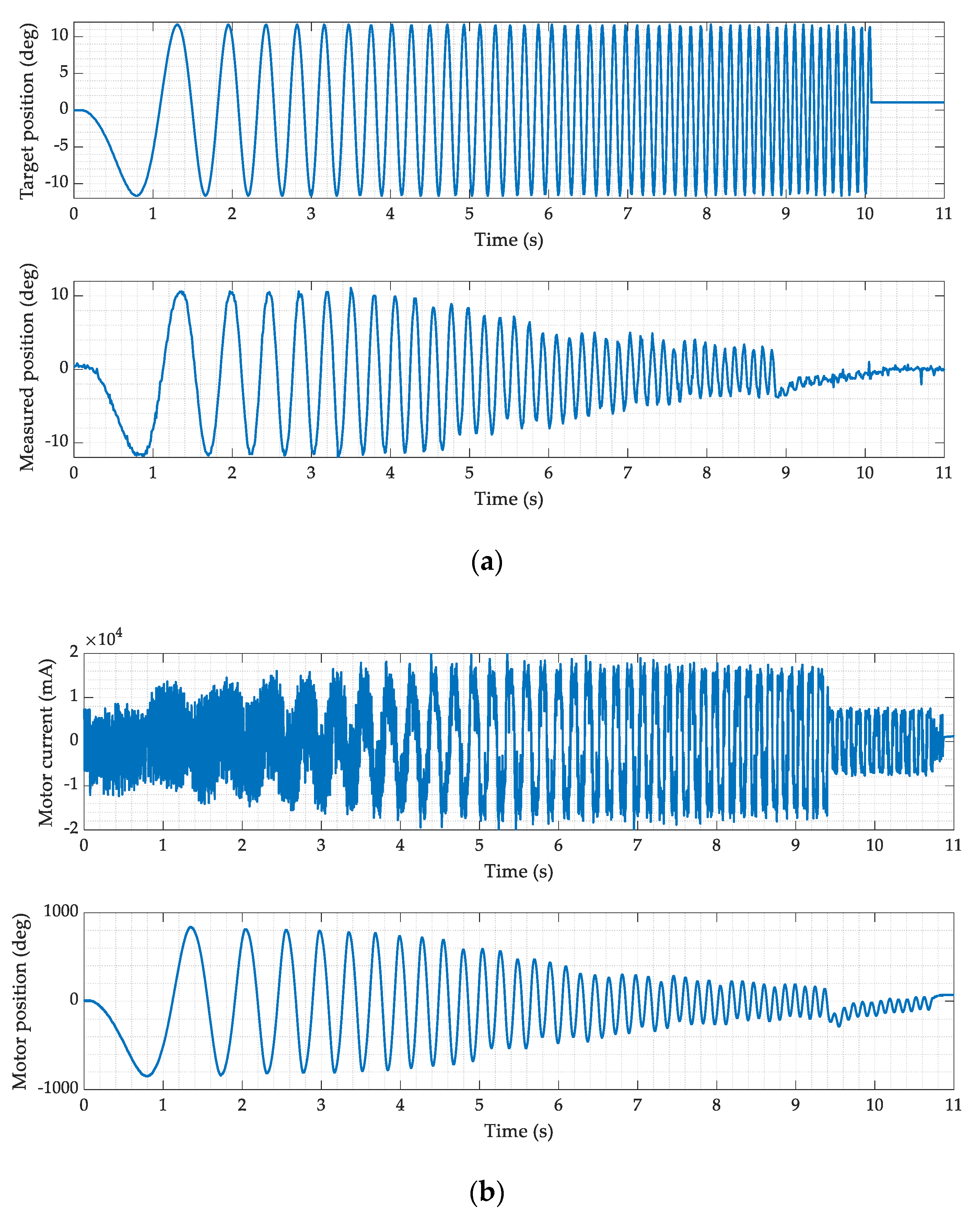
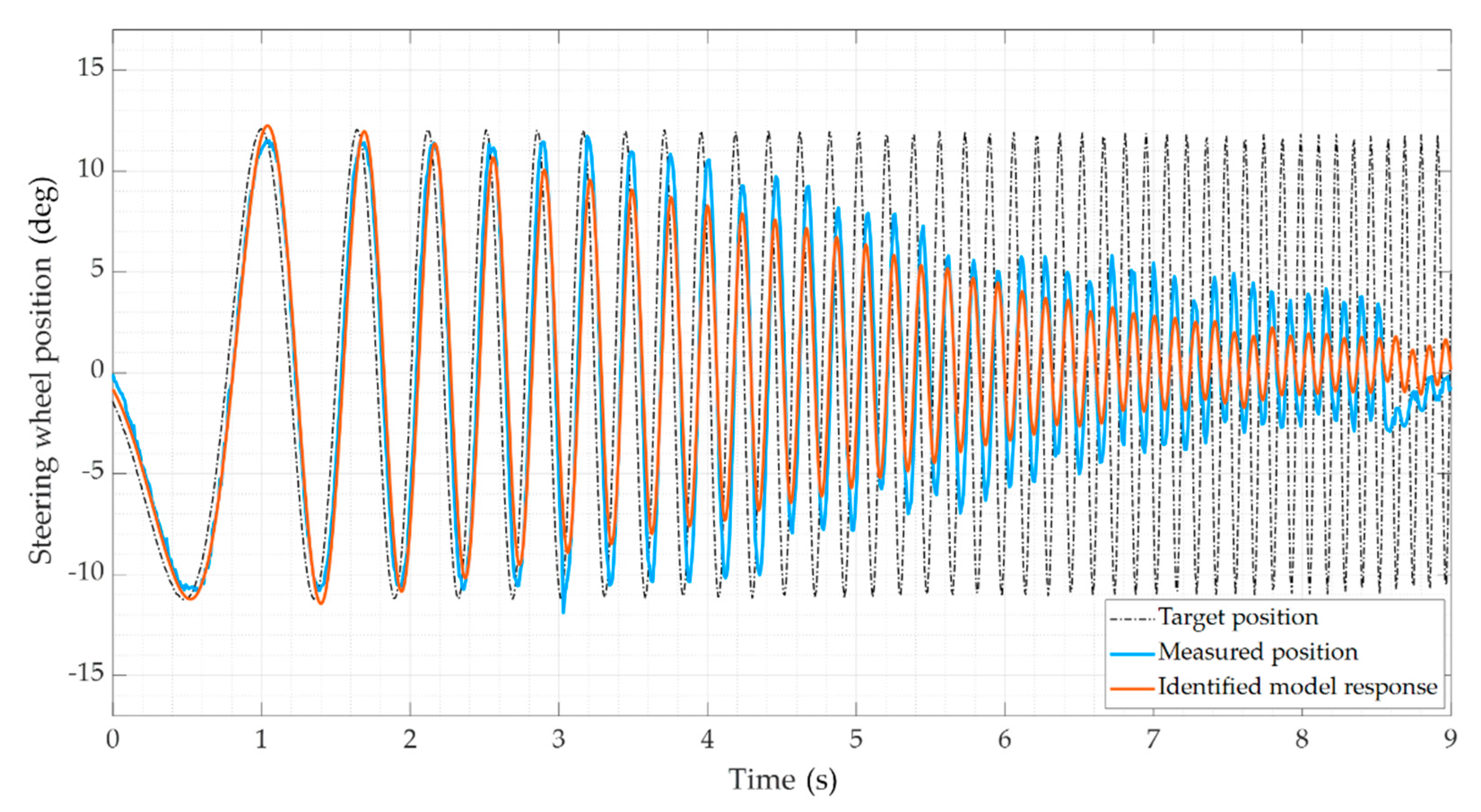
4.2. Sine-Sweep Test
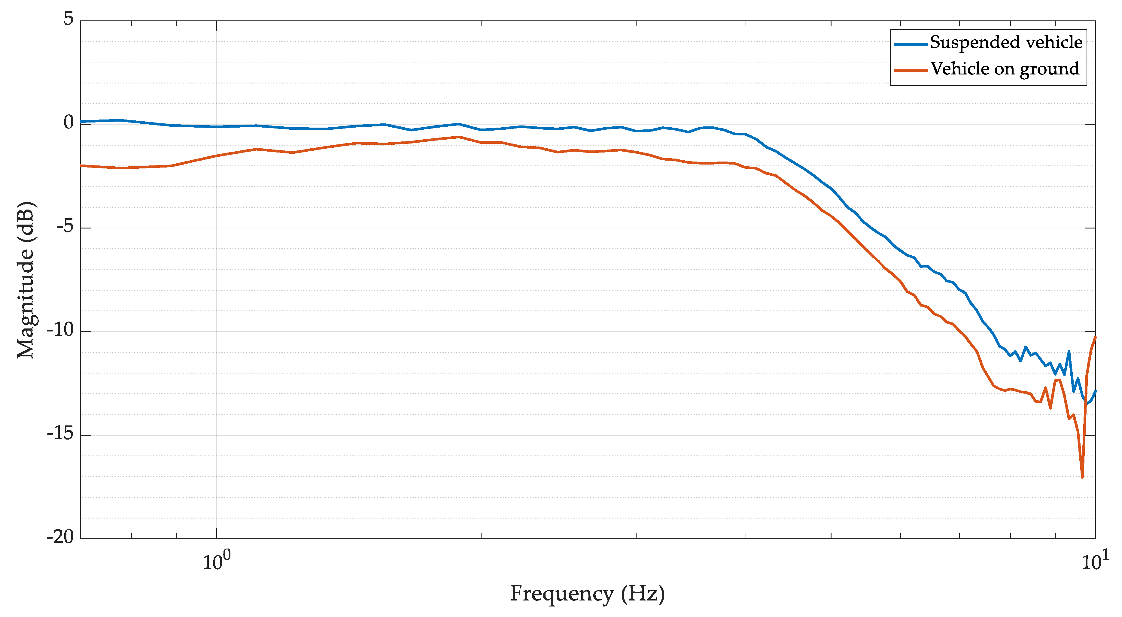
4.3. System Identification
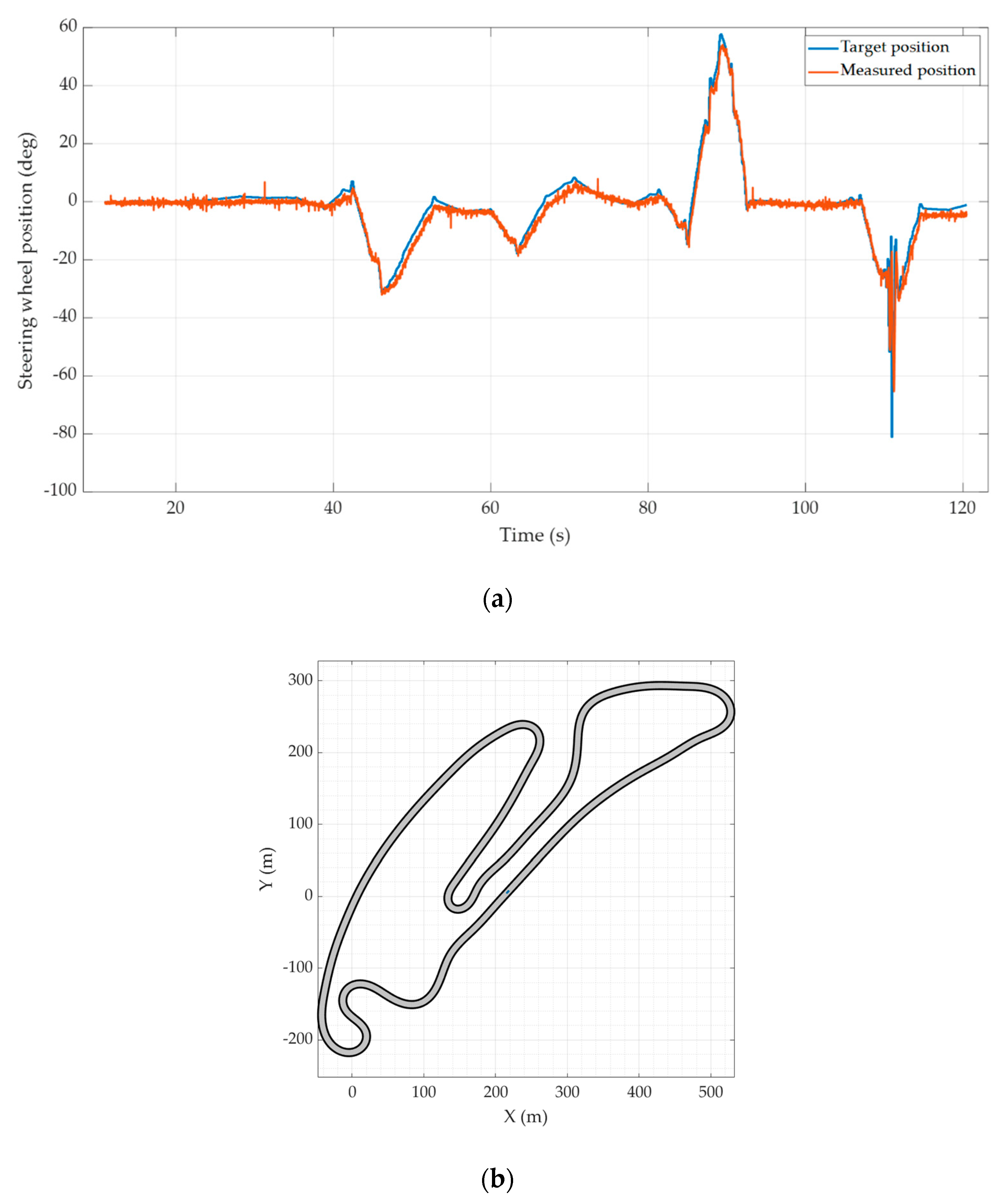
4.4. Autonomous Driving Test
5. Conclusions
Author Contributions
Funding
Institutional Review Board Statement
Informed Consent Statement
Data Availability Statement
Acknowledgments
Conflicts of Interest
References
- PwC. Available online: https://www.pwc.com/en/industries/automotive/Publications/eascy.html (accessed on 15 January 2021).
- Mc Kinsey Center for Future Mobility. Available online: https://www.mckinsey.com/features/mckinsey-center-for-future-mobility/overview/autonomous-driving (accessed on 15 January 2021).
- SAE J3016—Levels of Driving Automation. Available online: https://www.sae.org/news/2019/01/sae-updatesj3016automateddrivinggraphic#:~:text=The%20J3016%20standard%20defines%20six,graphic%20first%20deployed%20in%202016 (accessed on 15 January 2021).
- Mehrabi, N.; Azad, N.L.; McPhee, J. Optimal disturbance rejection control design for electric power steering systems. In Proceedings of the 2011 50th IEEE Conference on Decision and Control and European Control Conference, Orlando, FL, USA, 12–15 December 2011; pp. 6584–6589. [Google Scholar]
- Baharom, M.B.; Hussain, K.; Day, A.J. Design of full electric power steering with enhanced performance over that of hydraulic power-assisted steering. Proc. Inst. Mech. Eng. Part D J. Automob. Eng. 2013, 227, 390–399. [Google Scholar] [CrossRef]
- Würges, M. New electrical power steering systems. Encycl. Automot. Eng. 2014, 1–17. [Google Scholar] [CrossRef]
- Liao, Y.G.; Du, H.I. Modelling and analysis of electric power steering system and its effect on vehicle dynamic behaviour. Int. J. Veh. Auton. Syst. 2003, 1, 153–166. [Google Scholar] [CrossRef]
- Fankem, S.; Müller, S. A new model to compute the desired steering torque for steer-by-wire vehicles and driving simulators. Veh. Syst. Dyn. 2014, 52 (Suppl. 1), 251–271. [Google Scholar] [CrossRef]
- Chen, X.; Chen, X. Control-Oriented Model for Electric Power Steering System (No. 2006-01-0938); SAE Technical Paper; SAE International: Warrendale, PA, USA, 2006. [Google Scholar]
- Groll, M.V.; Mueller, S.; Meister, T.; Tracht, R. Disturbance compensation with a torque controllable steering system. Veh. Syst. Dyn. 2006, 44, 327–338. [Google Scholar] [CrossRef]
- Govender, V.; Khazardi, G.; Weiskircher, T.; Keppler, D.; Müller, S. A PID and state space approach for the position control of an electric power steering. In 16 Internationales Stuttgarter Symposium; Springer: Wiesbaden, Germany, 2016; pp. 755–769. [Google Scholar]
- Carriere, S.; Caux, S.; Fadel, M. Optimal lqi synthesis for speed control of synchronous actuator under load inertia variations. IFAC Proc. Vol. 2008, 41, 5831–5836. [Google Scholar] [CrossRef]
- Liao, Y.G.; Du, H.I. Cosimulation of multi-body-based vehicle dynamics and an electric power steering control system. Proc. Inst. Mech. Eng. Part K J. Multi-Body Dyn. 2001, 215, 141–151. [Google Scholar] [CrossRef]
- Falcone, P.; Borrelli, F.; Asgari, J.; Tseng, H.E.; Hrovat, D. Predictive active steering control for autonomous vehicle systems. IEEE Trans. Control. Syst. Technol. 2007, 15, 566–580. [Google Scholar] [CrossRef]
- Park, M.; Lee, S.; Han, W. Development of Steering Control System for Autonomous Vehicle Using Geometry-Based Path Tracking Algorithm. Etri J. 2015, 37, 617–625. [Google Scholar] [CrossRef]
- Govender, V.; Müller, S. Modelling and position control of an electric power steering system. IFAC PapersOnLine 2016, 49, 312–318. [Google Scholar] [CrossRef]
- Zakaria, M.I.; Husain, A.R.; Mohamed, Z.; Shah, M.B.N. Steering control of a steer-by-wire system vehicle with time delay and actuator saturation via anti-windup controller. Eng. Appl. Sci. Res. 2019, 46, 72–78. [Google Scholar]
- Khan, I.; Feraco, S.; Bonfitto, A.; Amati, N. A model predictive control strategy for lateral and longitudinal dynamics in autonomous driving. In Volume 4: 22nd International Conference on Advanced Vehicle Technologies (AVT), Proceedings of the ASME 2020 International Design Engineering Technical Conferences and Computers and Information in Engineering Conference, Virtual, Online, 17–19 August 2020; ASME: New York, NY, USA, 2020; p. V004T04A004. [Google Scholar]
- Nguyen, V.G.; Guo, X.; Zhang, C.; Tran, X.K. Parameter Estimation, Robust Controller Design and Performance Analysis for an Electric Power Steering System. Algorithms 2019, 12, 57. [Google Scholar] [CrossRef] [Green Version]
- Naranjo, J.E.; González, C.; García, R.; de Pedro, T. Electric power steering automation for autonomous driving. In Proceedings of the International Conference on Computer Aided Systems Theory, Las Palmas de Gran Canaria, Spain, 7–11 February 2005; Springer: Berlin/Heidelberg, Germany, 2005; pp. 519–524. [Google Scholar]
- Formula Student 2020 Rulebook. Available online: https://www.formulastudent.de/all/2020/rules/FSRules-2020-V1 (accessed on 7 December 2020).
- Kabzan, J.; de la Iglesia Valls, M.; Reijgwart, V.; Hendrikx, H.F.C.; Ehmke, C.; Prajapat, M.; Bühler, A.; Gosala, N.; Gupta, M.; Sivanesan, R.; et al. Amz driverless: The full autonomous racing system. J. Field Robot. 2020, 37, 1267–1294. [Google Scholar] [CrossRef]
- Feraco, S.; Luciani, S.; Bonfitto, A.; Amati, N.; Tonoli, A. A local trajectory planning and control method for autonomous vehicles based on the RRT algorithm. In Proceedings of the 2020 AEIT International Conference of Electrical and Electronic Technologies for Automotive (AEIT AUTOMOTIVE), Torino, Italy, 18–20 November 2020; pp. 1–6. [Google Scholar] [CrossRef]
- Maxon Group. Epos 4 Positioning Controller Application Notes; Edition 2019-11; Maxon Group: Sachseln, Switzerland, 2019. [Google Scholar]


| Parameter | Description | Value | Unit |
|---|---|---|---|
| Resistance | () | ||
| Inductance | () | ||
| Torque constant | () | ||
| Speed constant | () | ||
| Torque/speed gradient | () | ||
| No load current | () | ||
| No load speed | () |
| Parameter | Description | Value | Unit |
|---|---|---|---|
| Rotor inertia | () | ||
| Ball screw mass | () | ||
| Rack mass | () | ||
| Belt to ball screw ratio | 2 | (-) | |
| Ball screw lead | () | ||
| Pinion C-factor | () | ||
| Rack displacement to wheel toe angle ratio | () | ||
| Longitudinal distance tie rod-kingpin axis | 0.049 | (m) |
| Parameter | Description | Value | Unit |
|---|---|---|---|
| Current controller P gain | () | ||
| Current controller I gain | ) | ||
| Position controller P gain | () | ||
| Position controller I gain | () | ||
| Position controller D gain | () | ||
| Velocity feedforward | () | ||
| Acceleration feedforward | () |
| Parameter | Description | Value | Unit |
|---|---|---|---|
| Ball screw inertia | (kg) | ||
| Steering wheel inertia | (kg) | ||
| Wheel inertia | (kg) | ||
| Belt stiffness | () | ||
| Belt damping | () | ||
| Ball screw damping | () | ||
| Torsion bar stiffness | () | ||
| Torsion bar damping | () | ||
| Steering wheel damping | 1.59 | () |
Publisher’s Note: MDPI stays neutral with regard to jurisdictional claims in published maps and institutional affiliations. |
© 2021 by the authors. Licensee MDPI, Basel, Switzerland. This article is an open access article distributed under the terms and conditions of the Creative Commons Attribution (CC BY) license (https://creativecommons.org/licenses/by/4.0/).
Share and Cite
Manca, R.; Circosta, S.; Khan, I.; Feraco, S.; Luciani, S.; Amati, N.; Bonfitto, A.; Galluzzi, R. Performance Assessment of an Electric Power Steering System for Driverless Formula Student Vehicles. Actuators 2021, 10, 165. https://0-doi-org.brum.beds.ac.uk/10.3390/act10070165
Manca R, Circosta S, Khan I, Feraco S, Luciani S, Amati N, Bonfitto A, Galluzzi R. Performance Assessment of an Electric Power Steering System for Driverless Formula Student Vehicles. Actuators. 2021; 10(7):165. https://0-doi-org.brum.beds.ac.uk/10.3390/act10070165
Chicago/Turabian StyleManca, Raffaele, Salvatore Circosta, Irfan Khan, Stefano Feraco, Sara Luciani, Nicola Amati, Angelo Bonfitto, and Renato Galluzzi. 2021. "Performance Assessment of an Electric Power Steering System for Driverless Formula Student Vehicles" Actuators 10, no. 7: 165. https://0-doi-org.brum.beds.ac.uk/10.3390/act10070165