
On the Lightweight Truss Structure for the Trash Can-Handling Robot †

1
School of Mechanical Engineering, Tongji University, Shanghai 201804, China
2
School of Automotive Studies, Tongji University, Shanghai 201804, China
*
Author to whom correspondence should be addressed.
†
This paper is an extended version of the conference paper: Yan Li; Jiawei Chen; Xiang Xu; Zhongyan Lin and Xinbo Chen. Optimization of Garbage Dumping Mechanism of Intelligent Sanitation Vehicle Based on Particle Swarm Algorithm. In Proceedings of the Intelligent Manufacturing and Automation Technology (MEMAT 2021), Guilin, China, 23–25 April 2021.
Actuators 2021, 10(9), 214; https://0-doi-org.brum.beds.ac.uk/10.3390/act10090214
Submission received: 15 July 2021
/
Revised: 12 August 2021
/
Accepted: 30 August 2021
/
Published: 31 August 2021
(This article belongs to the Special Issue Actuators for Intelligent Electric Vehicles)
Abstract
:With the rapid development of cities, the automated and intelligent garbage transportation has become an important direction for technological innovation of sanitation vehicles. In this paper, a vehicle-mounted trash can-handling robot is proposed. In order to reduce the cost of the robot and increase the loading capacity of the intelligent sanitation vehicles, a lightweight design method is proposed for the truss structure of the robot. Firstly, the parameters of the robot that are related to the load are optimized by multi-objective parameter optimization based on particle swarm optimization. Then, the material distribution of the truss structure is optimized by topology optimization under multiple load cases. Finally, the thickness of the truss structure parts is optimized by discrete optimization under multiple load cases. The optimization results show that the mass of the truss structure is reduced by 8.72%, the inherent frequency is increased by 61.08%, and the maximum stress is reduced by 10.98%. The optimization results achieve the goal of performance optimization of the intelligent sanitation vehicle, and prove the feasibility of the proposed lightweight design method.
1. Introduction
With the rapid development of cities, the production of municipal solid waste is increasing year by year, which has a non-negligible impact on the residents’ living standard [1,2]. With the goal of efficient and environmental-friendly urban cleaning work, the automated and intelligent garbage transportation has become an important direction for technological innovation of sanitation vehicles. To this end, the authors’ team has developed a vehicle-mounted trash can-handling robot. This robot has realized fully automated operations including trash can identification, trash can-handling, garbage dumping, and trash can resetting. In this paper, the composition and basic functions of the robot will be briefly introduced. On the basis of force analysis, this paper will study the lightweight design of the robot’s truss structure, in order to further improve its working performance.
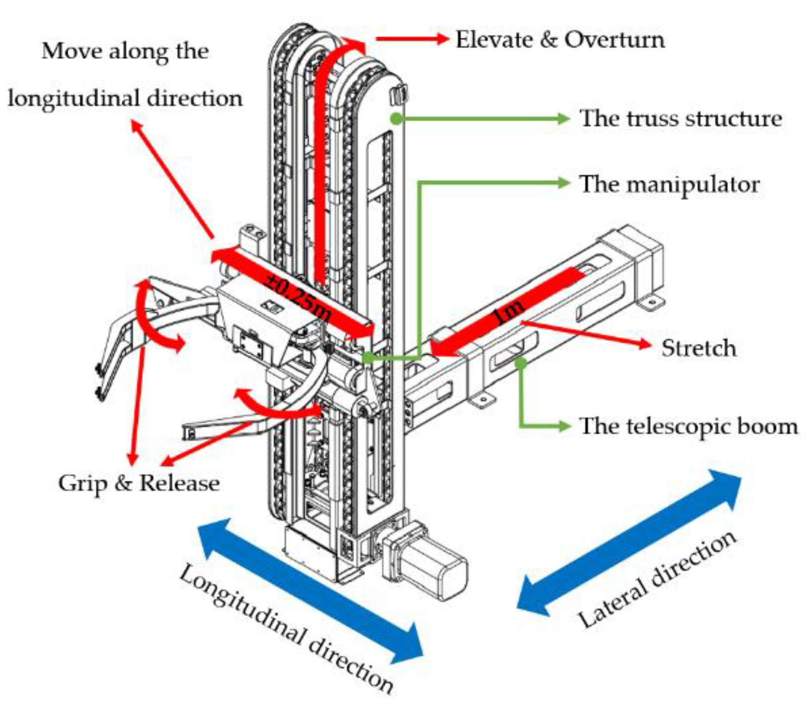
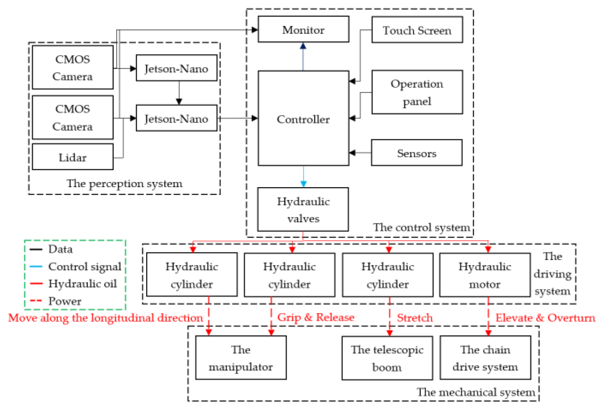
The developed trash can-handling robot is shown in Figure 1. The robot consists of a mechanical system, a driving system (hydraulic system), a control system and a perception system, as shown in Figure 2. Furthermore, the mechanical system is mainly composed of a manipulator, a telescopic boom and a truss structure. As the end-effector of the robot, the manipulator has a longitudinal adjustment range of ±0.25 m and a lateral telescopic distance of 1 m, which reduces the technical requirements for drivers. The driving system is mainly composed of hydraulic components such as hydraulic motor and hydraulic cylinder. The roller chain system is used to transmit the power of the hydraulic motor to drive the manipulator to move along the guide rail. The control system is mainly composed of sensors, controllers and a human–machine interaction module. The driver can set the robot in automatic or manual mode through the touch screen or the operation panel installed in the cab. Finally, the perception system is mainly composed of two cameras and a lidar. The lighting lamp is used to ensure good lighting conditions in the working environment.
The automatic workflow of the robot is as follows:
- 1
- After the driver parks the sanitation vehicle next to the trash can, the perception system sequentially detects the type of the trash can, the relative position of the trash can, pedestrians and obstacles. If the position of the trash can is beyond the working range of the robot, the driver will be prompted to make adjustments;
- 2
- The perception system converts the relative position information of the trash can into control data and then sends it to the control system;
- 3
- According to the preset control strategy, the control system controls the manipulator through the hydraulic components to complete the garbage loading operation.
As the robot is installed on the side of the vehicle, the heavy mechanical structure will cause the vehicle to roll, which has a detrimental impact on the vehicle’s handling performance and the robot’s control accuracy. Otherwise, the truss structure is the key load-bearing component of the robot. Due to the complex load of the robot, the truss structure is required to have high load-bearing capacity such as rigidity and strength. Therefore, the lightweight design of the truss structure is very important to ensure the performance of the robot.
However, currently all kinds of lifting equipment mainly use multi-link mechanism. The relevant research mainly focuses on the optimization of the position of the hinge points [3,4,5]. So, there is little research on the optimization of the lifting equipment similar to the robot in this paper. For the truss robot with similar structure, many scholars have carried out static characteristic analysis, dynamic characteristic analysis and comprehensive analysis on the truss structure. On this basis, the structural size of the truss structure is optimized [6,7,8,9]. However, in these studies, the loads and constraints of the truss structure are quite different from those of the robot in this paper. Therefore, the reference value of these studies is limited.
For lightweight design, the main methods are structure optimization, process lightweight and material lightweight [10,11,12]. The structure optimization can be further divided into size optimization, shape optimization and topology optimization. At present, size optimization and shape optimization have been widely used in engineering, such as lightweight design of loading platform of flat transport vehicle, lightweight design of soybean harvester’s frame, and comprehensive optimization design of column of double spindle horizontal machining center [13,14,15]. In addition, according to the type of design variables, size optimization can be divided into discrete size optimization and continuous size optimization [16]. In general, the results of continuous size optimization need to be rounded according to the available size parameters, so the results of discrete size optimization are more in line with the actual needs of engineering [17]. At the same time, there are more optimization variables for discrete optimization, such as cross section [18,19] and material [20,21,22]. In addition, the variables in the assignment problem and scheduling problem are also discrete, so discrete optimization is also applied to solve these problems. Furthermore, the discrete optimization that optimizes multiple optimization variables at the same time can obtain better optimization results [23]. However, due to the increase of the dimension of optimization variables, the solution of discrete size optimization is becoming more and more difficult. Some scholars reduce the computational cost by making discrete design variables continuous [24], while many other scholars propose their optimization methods based on different algorithms, which is a research hotspot in recent years. For example, Kaveh et al. [25] proposed an improved Shuffle Jaya algorithm for discrete size optimization of bone structure; Degertekin et al. [26] proposed an improved hybrid HS algorithm for large-scale truss structure’s size optimization.
Topology optimization is mainly used in the conceptual design stage. Common topological optimization methods include: homogenization method, variable density method, evolutionary structural optimization method, level set method, etc. [27]. At present, the research on topology optimization is divided into optimization strategy and engineering application. The purpose of the research on optimization strategy is to improve the accuracy of stress prediction [28,29]. The objects of engineering application include the optimization design of car body [30,31], the mechanism design of aero-engine [32,33], the optimization design of the compliant mechanism using composite materials [34,35], and the design of parts manufactured through additive manufacturing [36,37], etc. It can be seen that topology optimization has been applied in many disciplines.
Based on the research above, it can be found that most of the current researches are focused on the optimization methods in specific design stage. Without a systematic design route, the optimization methods can only meet specific engineering needs. At the same time, the trash can-handling robot proposed in this paper also has the demand of performance optimization. Therefore, based on the load analysis and optimization, the topology optimization in the conceptual design stage and the discrete size optimization in the engineering design stage, this paper proposes a lightweight design method for the truss structure in the robot. The main research route of this paper is as follows: in the second chapter, the kinematic and dynamic equations of the manipulator is established. The multi-objective optimization of the parameters related to the robot’s load is carried out through the particle swarm algorithm to reduce the load of the truss structure. In the third chapter, three typical load cases of the truss structure are set, and the topology optimization of the truss structure under multiple load cases is carried out. In the fourth chapter, the discrete size optimization of the truss structure parts’ thickness under multiple load cases is carried out through the sequential quadratic programming solver. The fifth chapter summarizes the lightweight design method used in this paper.
2. Multi-Objective Optimization of Parameters Related to Robot Load
Some parameters of the robot will affect the load of its truss structure. Therefore, it is necessary to optimize these parameters first. In this chapter, this paper establishes the kinematic and dynamic equations of the manipulator. Then, the load-related parameters are optimized through the particle swarm algorithm.
2.1. Establishment of Kinematic Equation
This paper takes the movement of the manipulator after grabbing the trash can as the analysis object, and makes the following settings:
- There is no relative displacement between the manipulator and the trash can;
- The garbage in the trash can does not move during the whole operation, and the position of the center of mass remains unchanged;
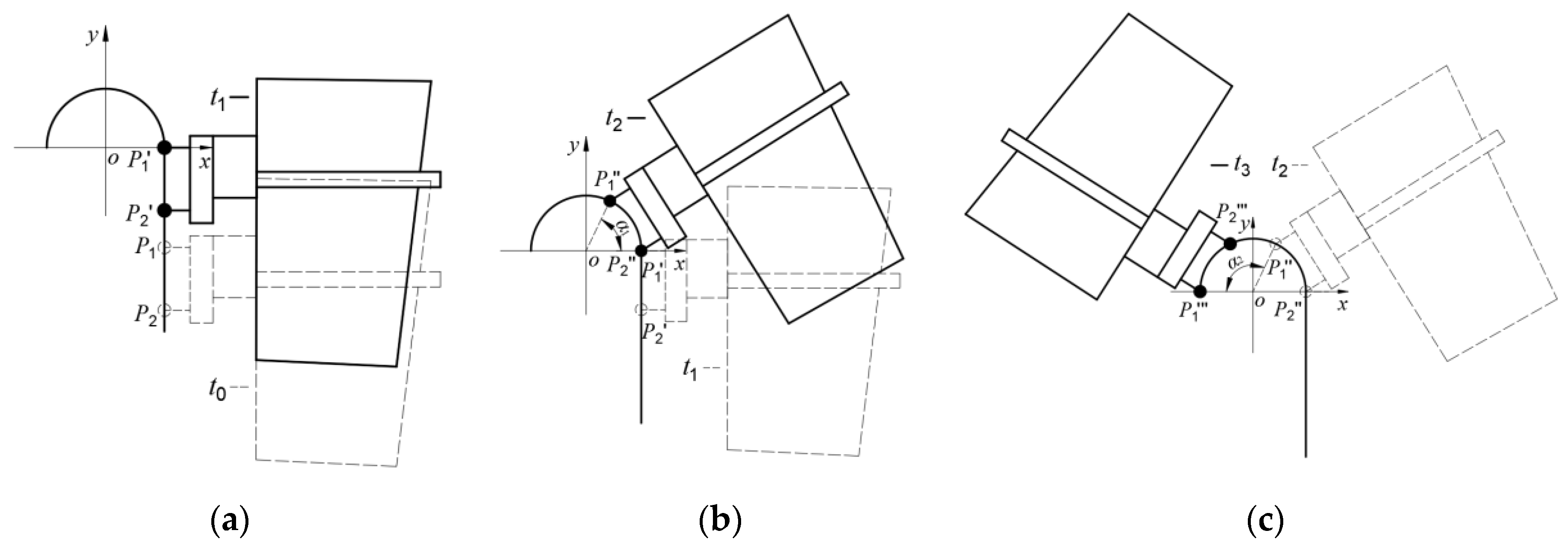
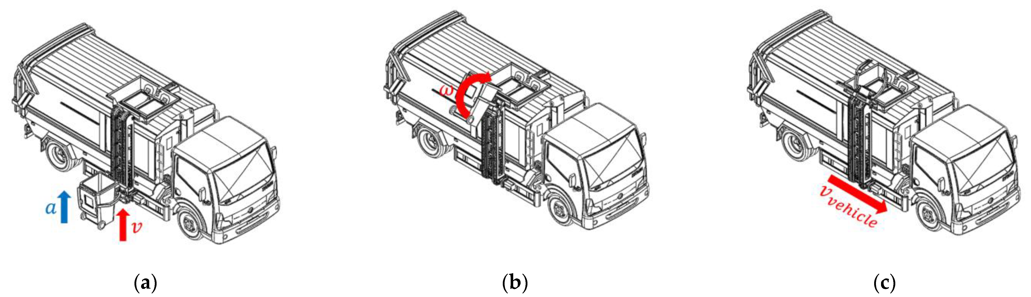
According to the time sequence, the movement of the manipulator can be divided into three stages, as shown in Figure 3. The lifting movement and the turning movement are respectively linear movement and circular movement, which will not be analyzed here. This paragraph will mainly analyze the transition movement.
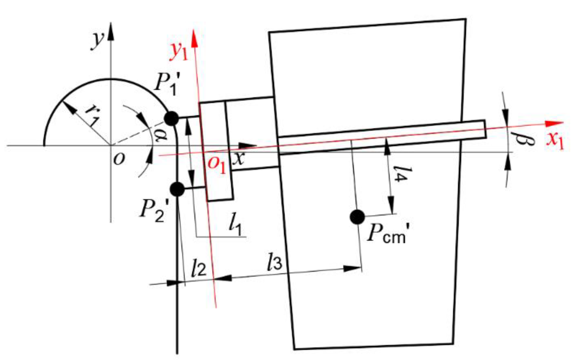
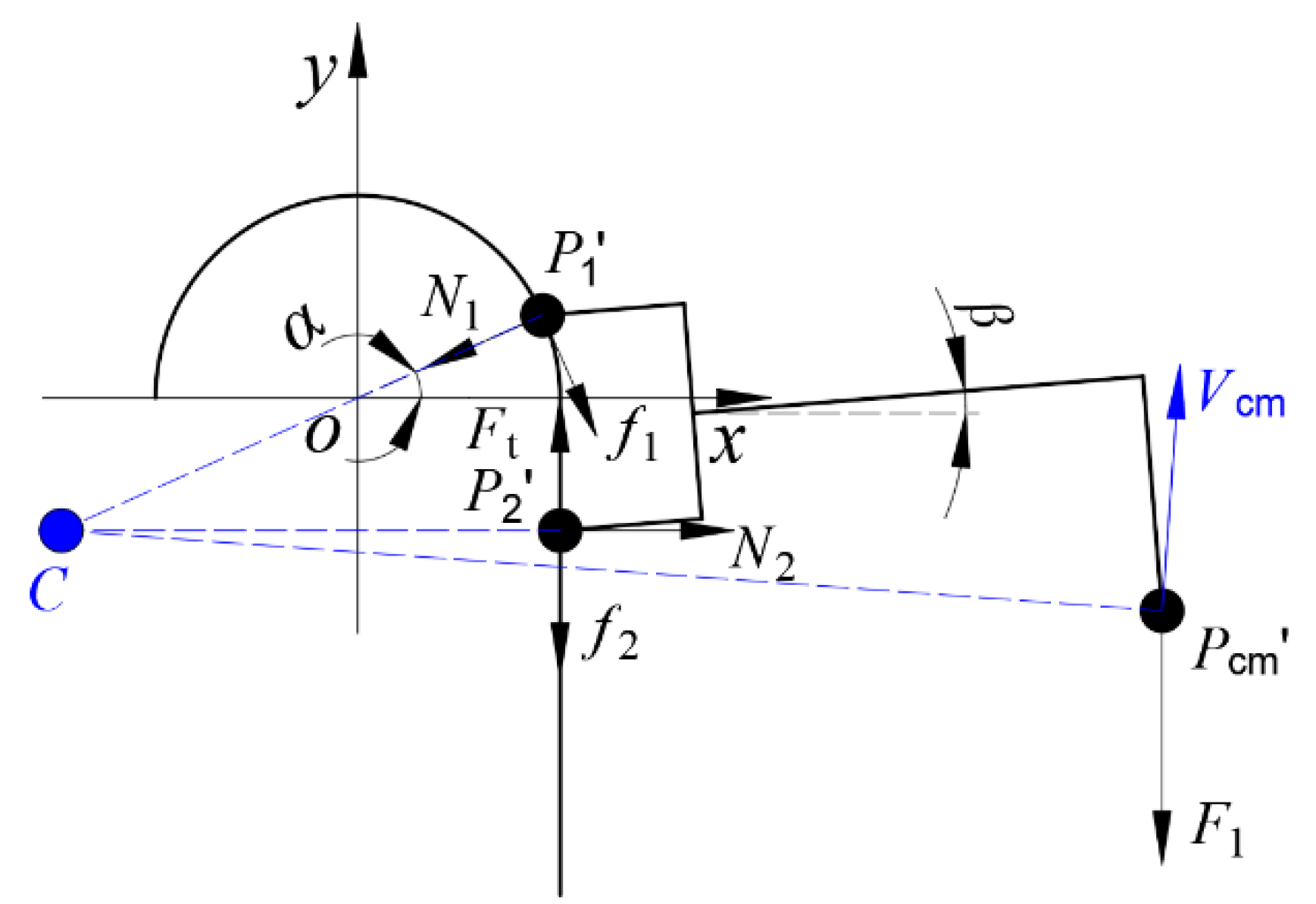
In the transition movement, the position of the manipulator is shown in Figure 4. In the figure, is the world coordinate system; is the tool coordinate system; is the center point of the upper groove wheels; is the center point of the lower groove wheels; is the equivalent center of mass of the manipulator and load; is the arc radius of the dumping track; is the center distance between the upper and lower groove wheels; is the distance between the point and the axis; is the distance between the point and the axis; is the distance between the point and the axis; is the rotation angle of the manipulator; is the pitch angle of the manipulator.
For the points and , the speed and acceleration can be expressed as follows:
In the equations, the superscript ‘c’ means that the quantity is in complex form; and are the coefficients indicating that the driving force acts on the axis of the upper or the lower groove wheels, and there are only two cases: or ; is the linear velocity of the chain system; and are unknown variables, and their value can be calculated through the following equations.
In the equations, the superscript ‘*’ means that the quantity is the conjugate complex number of itself.
Then the velocity and acceleration of the point can be obtained through the complex interpolation method [38], as shown in Equation (3).
2.2. Establishment of Dynamic Equation
Taking the scheme in which the driving force acts on the axis of the lower groove wheels as an example, the force analysis of the manipulator is shown in Figure 5. In the figure, is the instantaneous center of velocity of the manipulator; is the equivalent force of the gravity of the manipulator and load; is the driving force; and are the normal force; and are the friction force.
According to the theorem of kinetic energy and the balance relationship of forces, the dynamic equations of the manipulator in the lifting movement can be expressed as follows:
The dynamic equations of the manipulator in the transition movement can be expressed as follows:
In the equations, is the moving distance of the upper groove wheels in unit time; is the moving distance of the lower groove wheels in unit time; is the height change of the point in unit time; is the kinetic energy change of the manipulator and load in unit time.
The dynamic equations of the manipulator in the turning movement can be expressed as follows:
In the equations, is a fixed angle. It can be expressed as follows:
2.3. Mathematical Model of the Multi-Objective Optimization of the Load-Related Parameters
- 1
- Design variables: this paper takes the arc radius , the center distance and the time consumption of the dumping action as the design variables;
- 2
- Constraints: to ensure that the manipulator can dump garbage smoothly, the pitch angle of the manipulator must be greater than 135°;
- 3
- Optimization objective: the purpose of parameter optimization is to reduce the load on the truss structure. Therefore, the optimization objective is to minimize the maximum instantaneous power , the average power , the maximum change of the instantaneous driving force and the time consumption of the dumping action.
The mathematical model of the optimization of the load-related parameters can be expressed as follows:
2.4. Results of the Multi-Objective Optimization of the Load-Related Parameters
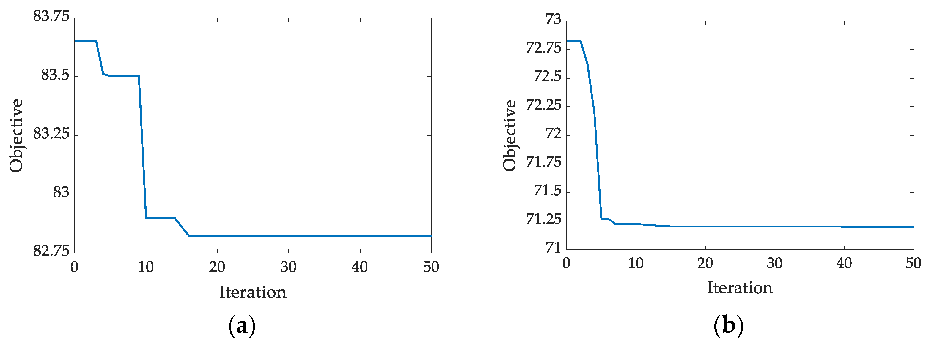
Particle swarm optimization (PSO) was proposed by Kennedy and Eberhart in 1995 [39]. In order to improve the optimization efficiency, this paper adopts particle swarm optimization algorithm with improved weight coefficient [40]. The process of the optimization iteration is shown in Figure 6.
The optimization results are shown in Table 1.
According to Table 1, both optimization scheme A and B have obvious optimization effect. The maximum instantaneous power of optimization scheme B is reduced by 1827.46 W, the average power is reduced by 701.61 W and the maximum change of the instantaneous driving force is reduced by 2093.6 N, which is more effective than that of the optimization scheme A. Therefore, optimization scheme B is the reasonable optimization scheme.
3. Topology Optimization of the Truss Structure under Multiple Load Cases
If the truss structure has a reasonable material distribution, the material can fully play its role, which is an important basis for the lightweight design [41]. In this chapter, this paper first analyzes and calculates the load on the truss structure, and then determines three typical load cases. Finally, the topology optimization of the truss structure under multiple load cases is carried out.
3.1. Analysis of the Load on the Truss Structure
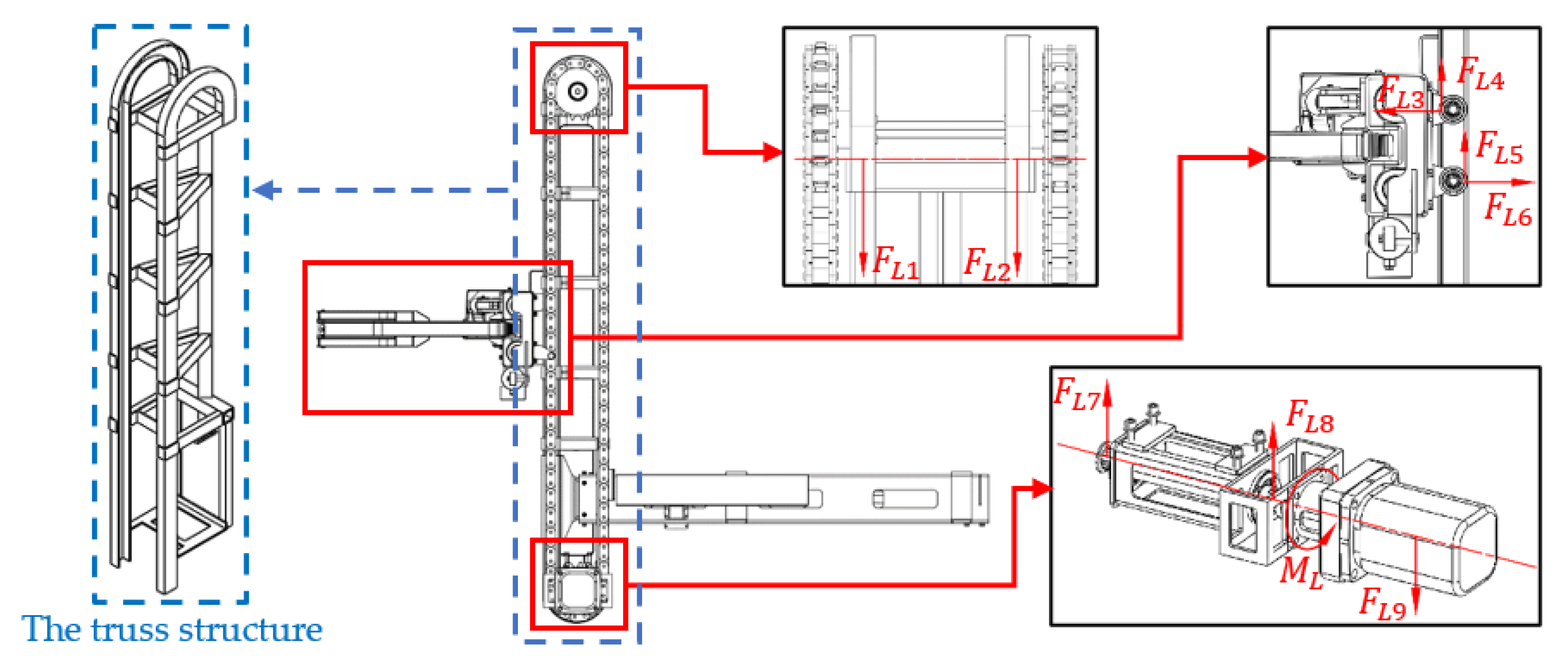
The load on the truss structure mainly comes from the manipulator and the roller chain system, as shown in Figure 7. The definition of each load is shown in Table 2.
According to the optimization results above, the detailed truss structure parameters are shown in Table 3. In the table, is the length of the vertical track, and is the coefficient of friction.
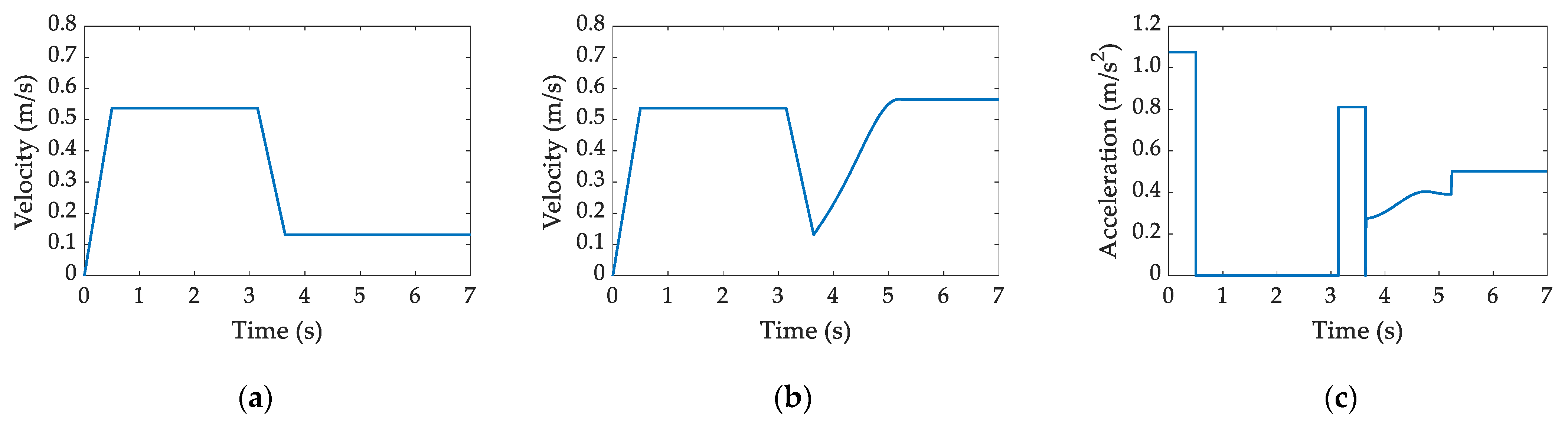
The control method of the robot is ‘Sliding Mode Variable Structure Control’ [42]. The preset linear velocity of the chain system is shown in Figure 8a. The corresponding speed and acceleration of the point are shown in Figure 8b,c.
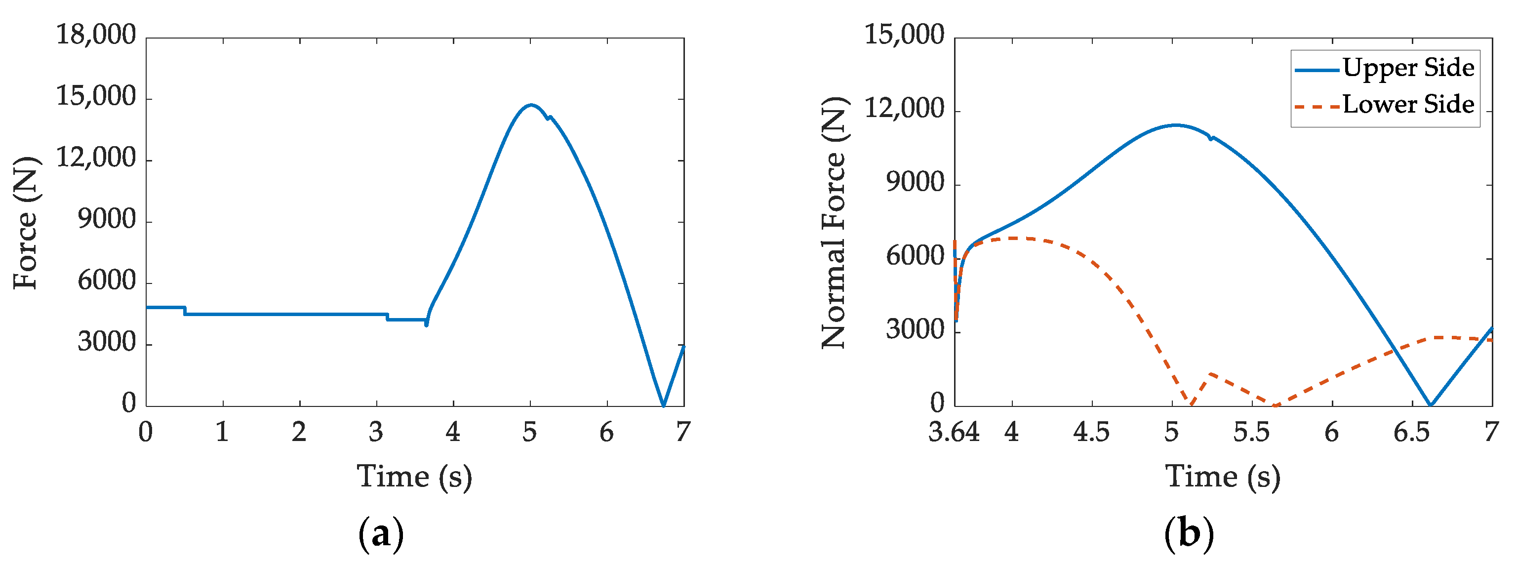
According to the dynamic equations, the driving force required for the motion of the manipulator and the normal force of the manipulator acting on the track are shown in Figure 9. It can be seen that when the manipulator enters the circular arc section of the track, the driving force and the normal force increase significantly. In the lifting motion, the driving force required by the manipulator is the largest when accelerating.
Then the calculation formula of the truss structure load defined in Table 2 can be expressed as follows:
In the formula, is the mass of the roller chain on one side; is the mass of a sprocket; is the mass of the hydraulic motor; is the equivalent moment of inertia of all rotating parts.
3.2. Topology Optimization under Multiple Load Cases
3.2.1. Determination of Load Cases
Based on the analysis and calculation results of the truss structure load, the states when the manipulator is in the acceleration lifting movement, the transition movement, and on standby are regarded as three typical load cases in this paper. The schematic diagrams of the typical load cases are shown in Figure 10.
The value of the truss structure load under three load cases are shown in Table 4.
3.2.2. Mathematical Model of Topology Optimization under Multiple Load Cases
In this paper, the optimization objective is to minimize the weighted strain energy of the truss structure under multiple load cases. The ratio of the optimized volume to the initial volume is the constraint. The mathematical model of the optimization can be expressed as follows:
In the formula, is the weighted strain energy; is the weight coefficient of the i-th load case, whose value is 1/3; is the strain energy of the i-th load case; is the optimized volume; is the initial volume; is the volume fraction; is the material density of the j-th unit.
3.2.3. Results of Topology Optimization under Multiple Load Cases
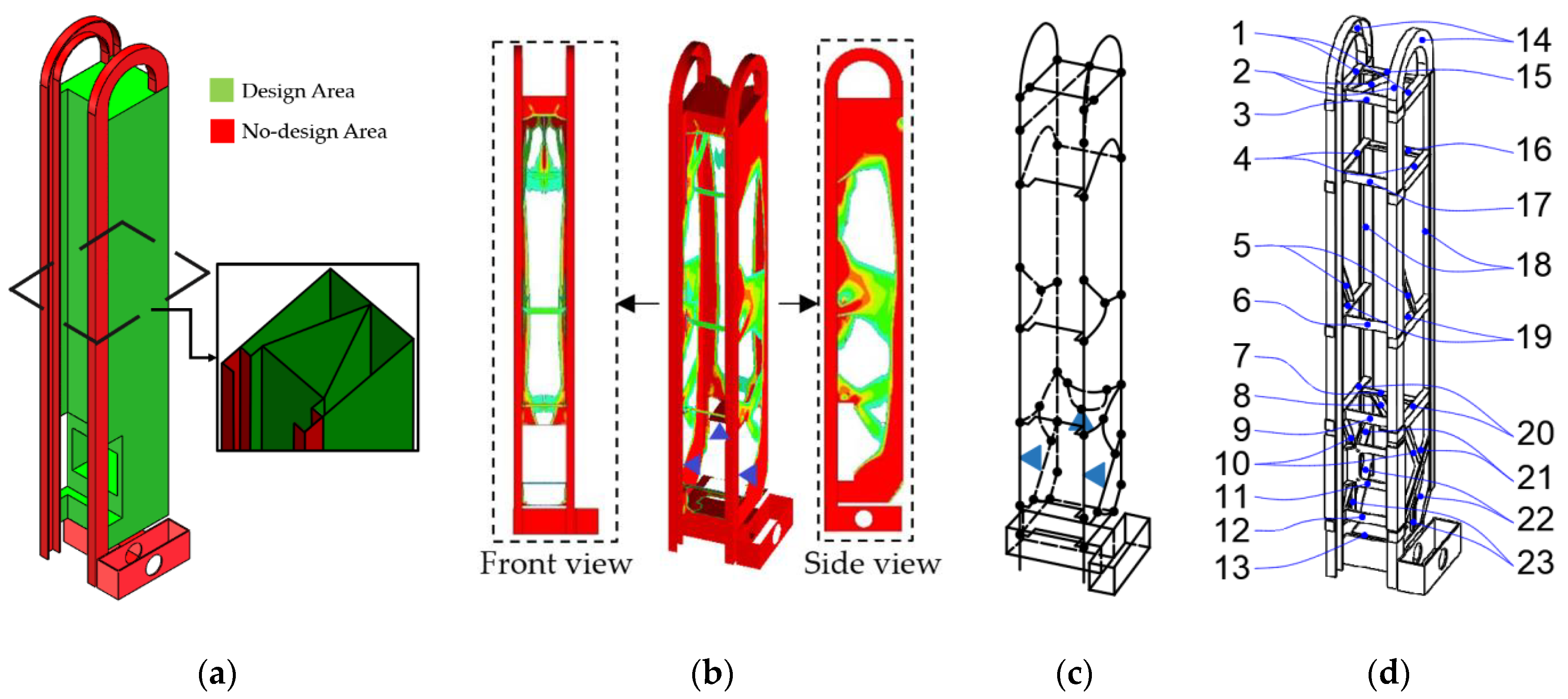
The truss structure is a kind of frame parts. The typical structure of this type of parts is cubic shape and triangular prism shape. According to the connection relationship between the truss structure and other parts, the truss structure can be designed as a combination of cubic shape and triangular prism shape. The optimization model is shown in Figure 11a.
Through the finite element optimization solver Optistruct, the material distribution of the truss structure is obtained, as shown in Figure 11b. After simplifying the material distribution, the corresponding force transmission route map is formed, as shown in Figure 11c. As the technological conditions and processing efficiency need to be considered in practical engineering, the truss structure is mainly welded by sheet metal parts and angle iron. The conceptual configuration model is shown in Figure 11d.
4. Discrete Optimization of the Truss Structure under Multiple Load Cases
Based on the conceptual configuration model, this chapter will optimize the section size of the parts. In this chapter, this paper firstly establishes the mathematical model of discrete optimization under multiple load cases. Then, the optimization is carried out based on different preference settings. Finally, this paper compares the optimization results.
4.1. Mathematical Model of Discrete Optimization under Multiple Load Cases
If the three parameters of the length, width and thickness of the part are all taken as optimization variables, the optimization will have a large feasible set. At the same time, the change of the length and width of different parts will cause the change of the connection form, which will increase the computational cost [43]. Therefore, this paper has determined the length and width of each part in the conceptual configuration model to improve the efficiency of optimization solution.
The optimization objective is to maximize the inherent frequency, and minimize the maximum stress and the mass of the truss structure under multiple load cases. The thickness of the parts is the optimization variable, and the yield strength of the material is the constraint. The mathematical model of discrete optimization can be expressed as follows:
In the formula, is the comprehensive optimization objective; is the thickness of the j-th part; is the maximum stress of the i-th load case; is the mass of the truss structure; and are the maximum and minimum mass of the truss structure under the constraint; is the inherent frequency of the truss structure; and are the maximum and minimum values in the optimization with the inherent frequency of the truss structure as the optimization objective; is the yield strength of the material; is the set of available material thickness; is the weight coefficient of the i-th load case, whose value is equal to ; and are the correction factors, whose value is 1/3 as well.
4.2. Results of Discrete Optimization under Multiple Load Cases
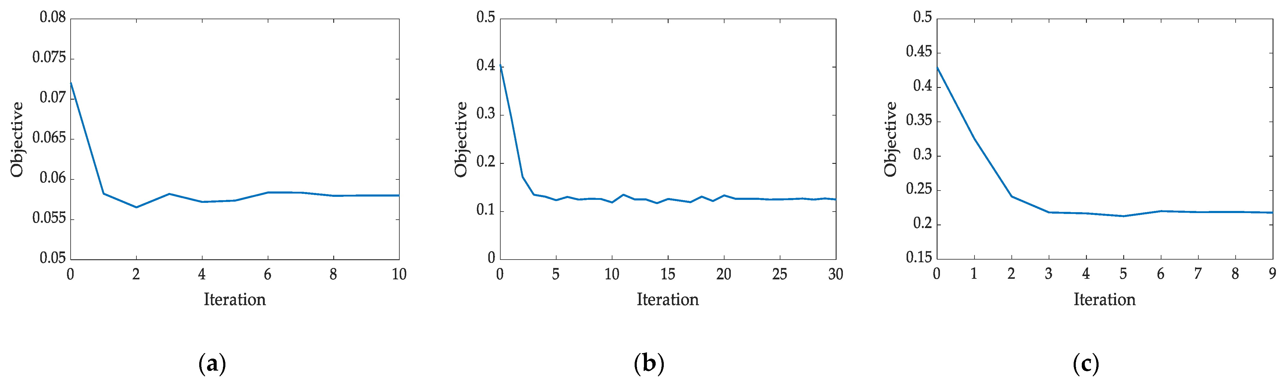
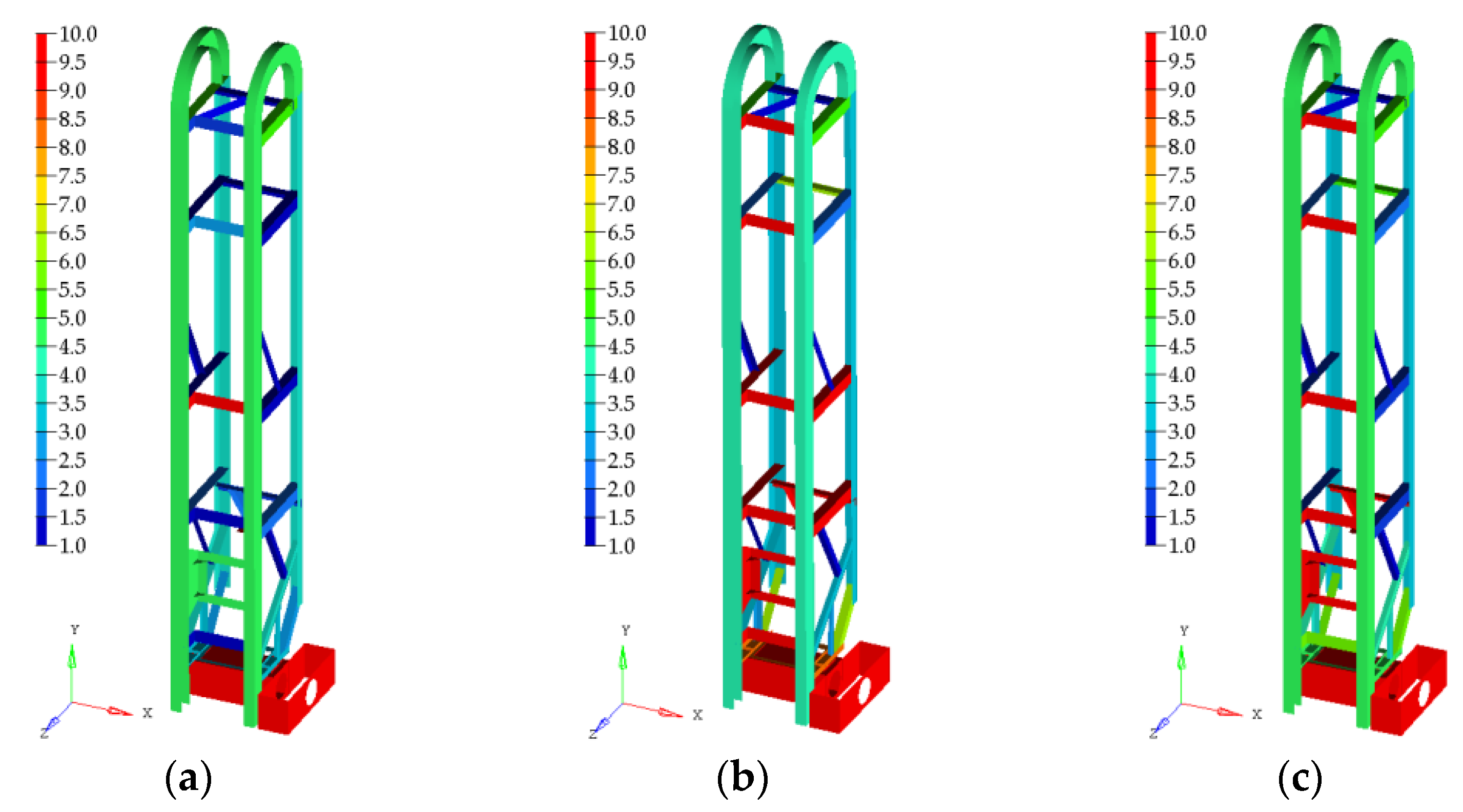
Due to the large difference in the density of different types of garbage [44], the typical loads of the robots that perform different tasks are different. In order to make the optimization more targeted, this paper sets preference mass (optimization scheme A), preference performance (optimization scheme B) and no preference (optimization scheme C) lightweight schemes respectively. Then the sequential quadratic programming (SQP) solver is applied to solve the mathematical model. The process of optimization iteration is shown in Figure 12, and the optimization results are shown in Figure 13.
The thickness of the truss structure parts is shown in Table 5.
It can be seen from Figure 13a and Table 6 that when the preference of the optimization scheme is set to mass, the mass of the truss structure is 58.37 kg, which is reduced by 18.99%. The inherent frequency, maximum stress and maximum deformation of the truss structure haven’t been optimized. The maximum stress is close to the material’s yield stress of 680 MPa. Therefore, this optimization scheme requires higher-strength materials. From Figure 13b and Table 6, it can be seen that when the preference of the optimization scheme is set to performance, the performance of the truss structure is significantly improved, while the mass is only reduced by 0.33 kg. The lightweight design effect is not significant. From Figure 13c and Table 6, it can be seen that when there is no preference for the optimization, the maximum stress is reduced by 70.97 MPa, the maximum deformation is increased by 0.2 mm, the inherent frequency is increased by 6.23 Hz, and the mass is reduced by 6.28 kg. The performance and mass of the truss structure have all been optimized. Therefore, optimization scheme C is the reasonable optimization scheme.
5. Lightweight Design Method of the Robot Truss Structure
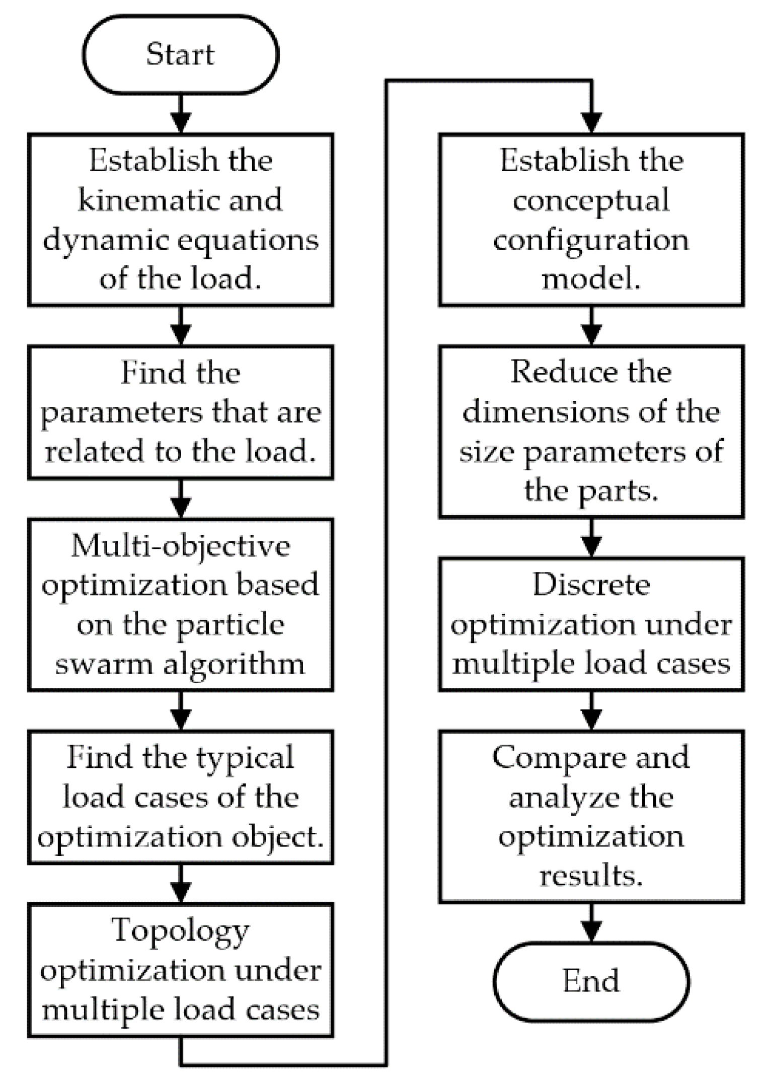
The lightweight design method used in this paper are summarized as follows:
- 1
- This paper first established the kinematic and dynamic equations of the manipulator (load). Then the variables that are related to the load were optimized through the particle swarm algorithm to reduce the load of the truss structure;
- 2
- This paper then determined the typical load cases of the truss structure. The topology optimization under multiple load cases was carried out to optimize the material distribution of the truss structure. The conceptual configuration model was established through model reconstruction method;
- 3
- Based on the conceptual configuration model, this paper finally reduced the dimensions of the optimization variables according to the technological conditions and processing efficiency. The sequential quadratic programming solver was applied to optimize the thickness of the truss structure parts under multiple load cases.
The flow chart of this method is shown in Figure 14.
6. Conclusions
Aiming at the performance optimization requirement of the trash can-handling robot, this paper optimizes its truss structure and proposes a systematic lightweight design method. The main research conclusions are as follows:
- 1
- In this paper, the kinematic and dynamic equations of the manipulator was established through the complex interpolation method and the theorem of kinetic energy. The particle swarm algorithm was used to optimize the load-related parameters. This provides a new method for the optimization of the equipment moving along the guide rail in the future. After the optimization, the maximum instantaneous power required by the robot for dumping garbage is reduced by 48.55%, the average power is reduced by 38.60%, and the maximum change of the instantaneous driving force is reduced by 85.70%;
- 2
- By analyzing the load of the truss structure during the operation, the states when the manipulator is in the acceleration lifting movement, the transition movement, and on standby are regarded as three typical load cases in this paper. Combined with practical engineering experience, due to the significant increase of the driving force, the transition movement needs special attention in the design and optimization of the equipment with similar structure;
- 3
- In this paper, three kinds of discrete optimization of the truss structure with different preference were carried out. According to the optimization results, the optimization scheme with no preference best meets the actual needs of the project. In this optimization scheme, the mass of the truss structure is reduced by 8.72%, the inherent frequency is increased by 61.08%, and the maximum stress is reduced by 10.98%;
- 4
- The lightweight design method proposed in this paper is a new optimization method as it includes load optimization. The results show that the method is effective for the optimization of the robot’s truss structure. This method can also be applied to the forward design or lightweight design of the actuators with similar structure, such as the column of vertical drilling machine. So, this method gives a reference value for actual projects.
Author Contributions
Conceptualization, J.C., Y.L., X.C. and X.X.; methodology, J.C. and X.X.; software, J.C. and X.X.; validation, J.C. and X.C.; investigation, J.C., Y.L., X.C. and X.X.; data curation, J.C. and Y.L.; writing—original draft preparation, J.C.; writing—review and editing, J.C., Y.L., X.C. and X.X.; visualization, J.C.; supervision, Y.L. and X.C.; project administration, X.C. All authors have read and agreed to the published version of the manuscript.
Funding
This research was funded by “Transverse Project of Tongji University- Research on the Key Technology of New Intelligent Self-loading and Unloading Compression Sanitation Vehicle and Its Engineering Project Two-Research on Intelligent Garbage Transfer Equipment” (grant number KH0170920191853) and “Project of Shanghai Science and Technology Commission” (grant number 20511104602).
Acknowledgments
The authors are thankful for the support of the IIV (Institute of Intelligent Vehicle).
Conflicts of Interest
The authors declare no conflict of interest.
References
- Chen, W.; Dong, Z. Analysis of Influencing Factors and Scale Prediction of Garbage Production in Shanghai - Research Based on Grey System Theory. Available online: https://oversea.cnki.net/KCMS/detail/detail.aspx?dbcode=CJFD&dbname=CJFDLAST2020&filename=ZSZY202005005&v=EBMK4Zr%25mmd2Fj8q0NJrqqoPvvXols3NuLzWluZqj8%25mmd2F%25mmd2FbI4rnr3%25mmd2FfcufjH4WFSksEXEB2 (accessed on 30 August 2021).
- Chu, X. Evaluation Research on the Implementation Effect of the Current Municipal Household Waste Classification Policy in Shanghai. Master’s Thesis, Harbin Engineering University, Harbin, China, June 2020. [Google Scholar]
- Wei, M. Performance Study and Improved Design of the Leakage-Free Lifting Mechanism for Garbage Truck. Master’s Thesis, Yangzhou University, Yangzhou, China, June 2020. [Google Scholar]
- Yin, C. Simulation Analysis and Key Components Lightweight of Food Garbage Truck Lifting Mechanism. Master’s Thesis, Yangzhou University, Yangzhou, China, June 2021. [Google Scholar]
- Yang, Q.; Xue, B. Kinematics and Dynamics Analysis of the Lifting Mechanism of the New-Type Sugarcane Harvester. Available online: https://oversea.cnki.net/KCMS/detail/detail.aspx?dbcode=CJFD&dbname=CJFDAUTO&filename=GXJX202105001&v=oOprQCOQxw%25mmd2F0om%25mmd2BakEi8%25mmd2B1vKqhiUVfZfmaW4Qlc6wJn4L8fA%25mmd2BhDhI16AKb7EK7qH (accessed on 30 August 2021).
- Wang, B. Coupling Characteristics Analysis and Structure Optimization of Truss Robot. Master’s Thesis, Hefei University of Technology, Hefei, China, April 2017. [Google Scholar]
- Wang, J.; Wang, X.; Fu, J.; Lu, G.; Jin, C.; Chen, Y. Static and dynamic characteristic analysis and structure optimization for crossbeam structure of heavy-duty truss robot. J. Zhejiang Univ. Eng. Sci. 2021, 55, 124–134. [Google Scholar]
- Li, Z.; Li, D.; Song, Y. Finite Element Analysis of Law of Thermo Mechanical Coupling Deformation and Dynamic Characteristics of Rail Beam of Truss Pipe Pulling Robot. Available online: https://oversea.cnki.net/KCMS/detail/detail.aspx?dbcode=CJFD&dbname=CJFDLAST2021&filename=JXQD202103029&v=Ldfdhg%25mmd2F21Z8X%25mmd2BOmhufPrWhMdseEIy8%25mmd2B40uPDb2asqtIjdi%25mmd2Fn57dALYr4myuf%25mmd2BD0m (accessed on 30 August 2021).
- Yuan, B. Analysis and Optimization of Truss Structure Based on Finite Element Method. Master’s Thesis, Yangzhou University, Yangzhou, China, December 2018. [Google Scholar]
- Shi, G.; Chen, Y.; Yang, Y.; Jiang, X.; Song, Z. BIW architecture multidisciplinary light weight optimization design. J. Mech. Eng. 2012, 48, 110–114. [Google Scholar] [CrossRef]
- Xu, X.; Chen, X.; Liu, Z.; Xu, Y.; Zhang, Y. Reliability-based design for lightweight vehicle structures with uncertain manufacturing accuracy. Appl. Math. Model. 2021, 95, 22–37. [Google Scholar] [CrossRef]
- Xu, X.; Chen, X.; Liu, Z.; Yang, J.; Xu, Y.; Zhang, Y.; Zhang, Y. Multi-Objective Reliability-Based Design Optimization for the Reducer Housing of Electric Vehicles. Available online: https://0-www-tandfonline-com.brum.beds.ac.uk/doi/abs/10.1080/0305215X.2021.1923704 (accessed on 30 August 2021).
- Wang, J.; Zhang, P.; Wang, C.; Han, S. Lightweight Optimization Design of the Flat Transport Vehicle’s Loading Platform Based on the high-Strength Steel. Available online: https://www.webofscience.com/wos/alldb/full-record/CSCD:6967249 (accessed on 30 August 2021).
- Li, Y.; Xu, Z.; Zhang, L.; Du, J.; Jiang, Y. Light Weight Design of Chassis Frame for a Soybean Harvester. Available online: https://www.webofscience.com/wos/alldb/full-record/CSCD:6600797 (accessed on 30 August 2021).
- Huang, W.; Huang, L.; Peng, T.; Liang, Q.; Luo, L. Comprehensive Optimal Design of the Column of Double Spindle Horizontal Machining Center. Available online: https://www.webofscience.com/wos/alldb/full-record/CSCD:6841618 (accessed on 30 August 2021).
- Gao, Y.; Ma, C.; Liu, Z.; Duan, Y.; Tian, L. Optimization of Multi-Material and Beam Cross-Sectional Shape and Dimension of Skeleton-Type Body. Available online: https://oversea.cnki.net/KCMS/detail/detail.aspx?dbcode=CAPJ&dbname=CAPJLAST&filename=JLGY20201216006&v=yiDx1rS1Ygw5mkOLat4bs%25mmd2BGYRDj9LAxCGX6WtMshjMK9bIGGSEc5LzRR634jCfOf (accessed on 17 December 2020).
- Cheng, M.; Prayogo, D.; Wu, Y.; Lukito, M. A hybrid harmony search algorithm for discrete sizing optimization of truss structure. Autom. Constr. 2016, 69, 21–33. [Google Scholar] [CrossRef]
- Yoshimura, M.; Nishiwaki, S.; Izui, K. A multiple cross-sectional shape optimization method for automotive body frames. J. Mech. Des. 2005, 127, 49–57. [Google Scholar] [CrossRef]
- Hou, W.; Wang, Z.; Zhang, W.; Zhang, H. Optimization design for auto-body beam section based on complex engineering constraints. J. Mech. Eng. 2014, 50, 127–133. [Google Scholar] [CrossRef]
- Cui, X.; Zhang, H.; Wang, S.; Zhang, L.; Ko, J. Design of lightweight multi-material automotive bodies using new material performance indices of thin-walled beams for the material selection with crashworthiness consideration. Mater. Des. 2011, 32, 815–821. [Google Scholar] [CrossRef]
- Cao, Y.; Wang, Z.; Zhou, C.; Wang, W. Optimization of circular-axis flexure hinge by considering material selection and geometrical configuration simultaneously. J. Mech. Eng. 2017, 53, 46–57. [Google Scholar] [CrossRef]
- Cui, A.; Zhang, H.; Yu, D.; Zhang, S.; Yang, Y. A study on material selection for multi-material autobody components based on PSI method. Automot. Eng. 2018, 40, 239–244+233. [Google Scholar]
- Zhao, Y.; Li, Y.; Chen, D.; Hou, W. Optimization Design Method of Multi-Material Car Body Structure Based on Modified Graphic Decomposition. Available online: https://www.webofscience.com/wos/alldb/full-record/CSCD:6721999 (accessed on 30 August 2021).
- Hou, Y.; Zhang, Y.; Liu, T. Optimization of standard cross-section type selection in steel frame structures based on gradient methods. Eng. Mech. 2013, 30, 454–462. [Google Scholar]
- Kaveh, A.; Hosseini, S.M.; Zaerreza, A. Improved shuffled Jaya algorithm for sizing optimization of skeletal structures with discrete variables. Structures 2021, 29, 107–128. [Google Scholar] [CrossRef]
- Degertekin, S.O.; Minooei, M.; Santoro, L.; Trentadue, B.; Lamberti, L. Large-scale truss-sizing optimization with enhanced hybrid HS algorithm. Appl. Sci. 2021, 11, 3270. [Google Scholar] [CrossRef]
- Xing, G.; Sun, Z.; Cui, X.; Wu, W.; Jia, P.; Jia, Z. Topological Optimization Design of Aero-Engine Support Structure under Multiple Loading Conditions. Available online: https://www.webofscience.com/wos/alldb/full-record/CSCD:6884473 (accessed on 30 August 2021).
- Ding, M.; Geng, D.; Zhou, M.; Lai, X. Topology optimization strategy of structural strength based on variable density method. J. Shanghai Jiaotong Univ. 2021, 55, 764–773. [Google Scholar]
- Picelli, R.; Townsend, S.; Brampton, C.; Norato, J.; Kim, H. Stress-based shape and topology optimization with the level set method. Comput. Meth. Appl. Mech. Eng. 2018, 329, 1–23. [Google Scholar] [CrossRef]
- Wu, Y.; Liu, X.; Wang, F. Topology optimization design of the bracket of a special vehicle based on FEA method. In Proceedings of the 2010 Second International Conference on Computational Intelligence and Natural Computing (CINC 2010), Wuhan, China, 13–14 September 2010; pp. 352–355. [Google Scholar]
- Chen, X.; Zhao, K.; Shen, C.; Zheng, K.; Lü, W. Topological Analysis and a Parametric Optimization Method for Aluminum Alloy Frame Body of Electric Vehicle. Available online: https://www.webofscience.com/wos/alldb/full-record/CSCD:6824257 (accessed on 30 August 2021).
- Kober, M.; Kühhorn, A.; Rademann, J.; Mück, B. Nonlinear topology optimization of centrifugally loaded aero-engine part with newly developed optimality-criteria based algorithm. Aerosp. Sci. Technol. 2014, 39, 705–711. [Google Scholar] [CrossRef]
- Yang, J.G.; Zhang, W.H.; Zhu, J. Optimal design of aero-engine stator structure with combined shape and topology optimization method. Mater. Sci. Forum. 2012, 1441, 623–626. [Google Scholar] [CrossRef]
- Tong, X.; Ge, W.; Gao, X.; Li, Y. Optimization of combining fiber orientation and topology for constant-stiffness composite laminated plates. J. Optim. Theory Appl. 2019, 181, 653–670. [Google Scholar] [CrossRef]
- Zhan, J.; Qin, Y.; Liu, M. Topological Design of Orthotropic Material Compliant Mechanisms Considering Variable Fiber Angle. Available online: https://oversea.cnki.net/KCMS/detail/detail.aspx?dbcode=CAPJ&dbname=CAPJLAST&filename=JXKX2021061000H&v=71l%25mmd2FrpOgPQe%25mmd2FKnRykBkh6qlngqWHUPsifvaU%25mmd2F6hoRHnoSON5jHQ3OqbSY%25mmd2Bd8QFdF (accessed on 30 August 2021).
- Chen, F.; Zhang, W.; Ye, D. Typical additive manufacturing joint design in civil aircrafts. Available online: https://oversea.cnki.net/KCMS/detail/detail.aspx?dbcode=CJFD&dbname=CJFDLAST2021&filename=YYLX202103028&v=rZj4GQjzvwxqTa%25mmd2BL4M4l9ZW0Xl%25mmd2Fi3K6bYFFr5QEPPM4D3aWKWJn6DLYj3Wi5ZAwc (accessed on 30 August 2021).
- Yan, M.; Tian, X.; Peng, G.; Li, D.; Yao, R.; Zhang, W.; Bai, R.; Meng, W. Performance Study of Lightweight Composites Equipment Section Support Fabricated by Selective Laser Sintering. Available online: http://www.cjmenet.com.cn/CN/Y2019/V55/I13/144 (accessed on 30 August 2021).
- Zhang, X. The Complex Interpolation Approach to Analysis of the Planar Motion of Rigid Bodies. Available online: https://oversea.cnki.net/KCMS/detail/detail.aspx?dbcode=CJFD&dbname=CJFDLAST2019&filename=DXWL201901002&v=oJ4RN9i2Lsp399gicG4Y20zdGmxcL4SLG%25mmd2B5zFM81vwlOaVKM%25mmd2FTal3kN3CZh6Rl9L (accessed on 30 August 2021).
- Kennedy, J.; Eberhart, R. Particle swarm optimization. In Proceedings of the ICNN’95—International Conference on Neural Networks, Perth, WA, Australia, 27 November–1 December 1995; pp. 1942–1948. [Google Scholar]
- Shi, Y.; Eberhart, R.C. Fuzzy adaptive particle swarm optimization. In Proceedings of the 2001 Congress on Evolutionary Computation, Seoul, Korea, 27–30 May 2001; pp. 101–106. [Google Scholar]
- Wang, D.; Shen, H.; Sun, Y.; Dong, H.; Ma, Y. A novel approach for conceptual structural design of complex machine elements. J. Mech. Eng. 2016, 52, 152–163. [Google Scholar] [CrossRef]
- Zhang, J.; Wang, J.; Lü, X. Control and Simulation of Robotic Arm System of Intelligent Sanitation Vehicle. Available online: https://oversea.cnki.net/KCMS/detail/detail.aspx?dbcode=CPFD&dbname=CPFDLAST2021&filename=ZGZN202011001048&v=Q7FS4XFR%25mmd2BG4Tb7oQsGIvtVN8qh5towQwpfrJytHAoT4%25mmd2BgRst1wWVbxKOAKiDukwEHtdAwf%25mmd2FRmMU%3d (accessed on 30 August 2021).
- Zhang, Z.; Li, H. The method of truss structure layout discrete variable optimization based on ant colony optimization. Chin. J. Comput. Mech. 2013, 30, 336–342. [Google Scholar]
- Liu, D.; Wang, Y.; Tong, Y.; Tong, Y.; Luo, Y.; Chen, W.; Tan, Z. Properties and disposal countermeasures of sorting waste. Environ. Sanitation Eng. 2013, 21, 27–30. [Google Scholar]
Figure 1.
The trash can-handling robot.

Figure 2.
The composition of the trash can-handling robot.

Figure 3.
Three stages of the manipulator’s movement: (a) lifting movement; (b) transition movement; (c) turning movement.
Figure 3.
Three stages of the manipulator’s movement: (a) lifting movement; (b) transition movement; (c) turning movement.

Figure 4.
Schematic diagram of the manipulator’s position.

Figure 5.
Force analysis diagram of the manipulator.

Figure 6.
The process of PSO optimization iteration: (a) optimization scheme A; (b) optimization scheme B.
Figure 6.
The process of PSO optimization iteration: (a) optimization scheme A; (b) optimization scheme B.

Figure 7.
The load on the truss structure.

Figure 8.
(a) Preset linear velocity of the chain system; (b) velocity of the point ; (c) acceleration of the point .
Figure 8.
(a) Preset linear velocity of the chain system; (b) velocity of the point ; (c) acceleration of the point .

Figure 9.
(a) Driving force required for the motion of the manipulator; (b) normal force of the manipulator acting on the track.
Figure 9.
(a) Driving force required for the motion of the manipulator; (b) normal force of the manipulator acting on the track.

Figure 10.
Three typical load cases: (a) load case A; (b) load case B; (c) load case C.

Figure 11.
Technical route of the topology optimization: (a) optimization model; (b) material distribution; (c) force transmission route map; (d) conceptual configuration model.
Figure 11.
Technical route of the topology optimization: (a) optimization model; (b) material distribution; (c) force transmission route map; (d) conceptual configuration model.

Figure 12.
The process of optimization iteration: (a) optimization scheme A; (b) optimization scheme B; (c) optimization scheme C.
Figure 12.
The process of optimization iteration: (a) optimization scheme A; (b) optimization scheme B; (c) optimization scheme C.

Figure 13.
Optimization results: (a) optimization scheme A; (b) optimization scheme B; (c) optimization scheme C.
Figure 13.
Optimization results: (a) optimization scheme A; (b) optimization scheme B; (c) optimization scheme C.

Figure 14.
Flow chart of the method.


Table 1.
Results of the multi-objective optimization of the load-related parameters.
| Parameter | Initial Design Scheme 1 | Optimization Scheme A 2 | Optimization Scheme B 3 |
|---|---|---|---|
| (mm) | 120 | 130 | 148 |
| (mm) | 150 | 157 | 210 |
| (s) | 2 | 3.45 | 3.36 |
| (W) | 3764.17 | 2028.33 | 1936.71 |
| (W) | 1817.43 | 1028.25 | 1115.82 |
| (N) | 2442.92 | 722.22 | 349.32 |
1 The initial design scheme is the design scheme of the prototype. 2 The driving force in optimization scheme A acts on the axis of the upper groove wheels. 3 The driving force in optimization scheme B acts on the axis of the lower groove wheels.
Table 2.
The definition of the load.
| Load | Definition |
|---|---|
| , | The force of the driven sprocket assembly acting on the truss structure. |
| , | The force of the groove wheels acting on the track. |
| , | The friction force of the groove wheels acting on the track. |
| , | The force of the drive sprocket assembly acting on the truss structure. |
| The gravity of the hydraulic motor. | |
| The torque of the hydraulic motor acting on the truss structure. |
Table 3.
Parameters of the truss structure.
| (kg) | |||||||
|---|---|---|---|---|---|---|---|
| 148 | 210 | 68.5 | 383.65 | 308.84 | 1720 | 320.35 | 0.1 |
Table 4.
The value of the truss structure load.
| Load Case | ||||||||||
|---|---|---|---|---|---|---|---|---|---|---|
| Load case A | 5160.07 | 5160.07 | 3379.75 | 337.97 | 337.97 | 3379.75 | 2335.97 | 2335.97 | 342.02 | 716.12 |
| Load case B | 15,041.05 | 15,041.05 | 5721.5 | 572.15 | 57.08 | 570.75 | 7276.46 | 7276.46 | 342.02 | 2178.05 |
| Load case C | 3620.2 | 3620.2 | 2169.76 | 0 | 0 | 280.14 | 2149.46 | 2149.46 | 342.02 | 660.46 |
Table 5.
The thickness of the truss structure parts.
| Part Number | Initial Design Scheme 1 (mm) | Optimization Scheme A (mm) | Optimization Scheme B (mm) | Optimization Scheme C (mm) |
|---|---|---|---|---|
| 1 | 5.0 | 5.0 | 5.0 | 5.0 |
| 2 | 5.0 | 1.0 | 1.0 | 1.0 |
| 3 | 4.0 | 1.5 | 10.0 | 10.0 |
| 4 | 5.0 | 1.0 | 2.0 | 2.0 |
| 5 | 3.0 | 1.0 | 1.0 | 1.0 |
| 6 | 4.0 | 10.0 | 10.0 | 10.0 |
| 7 | 5.0 | 1.5 | 10.0 | 9.0 |
| 8 | 3.0 | 2.0 | 10.0 | 10.0 |
| 9 | 4.0 | 1.0 | 10.0 | 10.0 |
| 10 | 3.0 | 1.0 | 1.0 | 1.0 |
| 11 | 4.0 | 4.5 | 9.5 | 10.0 |
| 12 | 4.0 | 1.0 | 10.0 | 5.5 |
| 13 | 5.0 | 3.0 | 8.0 | 4.5 |
| 14 | 5.0 | 4.5 | 4.5 | 4.5 |
| 15 | 5.0 | 1.0 | 1.0 | 1.0 |
| 16 | 5.0 | 1.0 | 6.0 | 5.0 |
| 17 | 4.0 | 2.5 | 10.0 | 10.0 |
| 18 | 5.0 | 3.5 | 3.0 | 3.0 |
| 19 | 5.0 | 1.0 | 9.5 | 1.5 |
| 20 | 5.0 | 2.0 | 9.5 | 1.5 |
| 21 | 5.0 | 3.5 | 3.0 | 4.0 |
| 22 | 5.0 | 2.5 | 6.0 | 5.5 |
| 23 | 3.0 | 3.0 | 2.5 | 3.5 |
1 The initial design scheme is established according to the prototype. For example, if the thickness of the guide rail in the prototype is 5 mm, the thickness of the guide rail in the initial design scheme is also 5 mm.
Table 6.
Performance comparison of optimization schemes.
| Performance | Initial Design Scheme | Optimization Scheme A | Optimization Scheme B | Optimization Scheme C |
|---|---|---|---|---|
| (kg) | 72.05 | 58.37 | 71.72 | 65.77 |
| (Hz) | 10.20 | 10.38 | 16.92 | 16.43 |
| (mm) | 1.10 | 1.75 | 0.93 | 1.08 |
| (mm) | 2.19 | 3.41 | 1.98 | 2.39 |
| (mm) | 0.77 | 1.51 | 0.64 | 0.77 |
| (MPa) | 218.16 | 273.30 | 216.47 | 222.75 |
| (MPa) | 646.09 | 666.74 | 573.67 | 575.12 |
| (MPa) | 202.37 | 322.62 | 128.29 | 226.16 |
Publisher’s Note: MDPI stays neutral with regard to jurisdictional claims in published maps and institutional affiliations. |
© 2021 by the authors. Licensee MDPI, Basel, Switzerland. This article is an open access article distributed under the terms and conditions of the Creative Commons Attribution (CC BY) license (https://creativecommons.org/licenses/by/4.0/).
Share and Cite
MDPI and ACS Style
Chen, J.; Li, Y.; Xu, X.; Chen, X. On the Lightweight Truss Structure for the Trash Can-Handling Robot. Actuators 2021, 10, 214. https://0-doi-org.brum.beds.ac.uk/10.3390/act10090214
AMA Style
Chen J, Li Y, Xu X, Chen X. On the Lightweight Truss Structure for the Trash Can-Handling Robot. Actuators. 2021; 10(9):214. https://0-doi-org.brum.beds.ac.uk/10.3390/act10090214
Chicago/Turabian StyleChen, Jiawei, Yan Li, Xiang Xu, and Xinbo Chen. 2021. "On the Lightweight Truss Structure for the Trash Can-Handling Robot" Actuators 10, no. 9: 214. https://0-doi-org.brum.beds.ac.uk/10.3390/act10090214
Note that from the first issue of 2016, this journal uses article numbers instead of page numbers. See further details here.