
In-Wheel Two-Speed AMT with Selectable One-Way Clutch for Electric Vehicles

1
State Key Laboratory of Automotive Simulation and Control, Jilin University, Changchun 130012, China
2
Qingdao Automotive Research Institute, Jilin University, Qingdao 266108, China
3
Clean Energy Automotive Engineering Center, Tongji University, Shanghai 201804, China
*
Author to whom correspondence should be addressed.
Actuators 2021, 10(9), 220; https://0-doi-org.brum.beds.ac.uk/10.3390/act10090220
Submission received: 28 July 2021
/
Revised: 15 August 2021
/
Accepted: 31 August 2021
/
Published: 2 September 2021
(This article belongs to the Special Issue Actuators for Intelligent Electric Vehicles)
Abstract
:To improve the efficiency of the electric vehicle (EV) drive systems and EV performance, the use of multi-speed transmissions and distributed drives has been studied extensively. In addition, to develop efficient and compact drive systems, new clutch solutions are needed. In this paper, we propose an in-wheel two-speed automatic mechanical transmission (IW-AMT) with a selectable one-way clutch (SOWC). The IW-AMT consists of a high-speed motor and a mechanical shift actuator, and it can realize shifting without power interruption, thus effectively reducing the unsprung mass and the technical specifications of the motor. We established a virtual prototype model of the IW-AMT to show the shifting process and evaluate the quality of shifting. The simulation results of the upshifting process indicated that the vehicle torque and velocity changed smoothly, and the maximum jerk is less than 10 m/s. Furthermore, to improve the jerk induced by the downshifting process, we analyzed the momentary state of the SOWC struts that are dropped and attempted to improve the jerk from two aspects: improving the wet multi-plate clutch (WMPC) combination curve and improving the SOWC structure. The results indicated that the downshift-induced jerk can be reduced to 13 m/s.
1. Introduction
Electric vehicles (EVs), as a promising way to reduce the greenhouse effect and alleviate the problem of climate change, have been extensively studied [1]. As a key component of EVs, the drive system has a direct impact on the energy efficiency of EVs. Therefore, it is extremely important to improve the efficiency of the drive system while satisfying vehicle performance standards [2].
Studies have demonstrated that integrating a multi-speed gearbox into the drive system can effectively help to utilize the high-efficiency range, improve motor efficiency, and reduce energy consumption [3,4]. Continuously variable transmission (CVT), and dual-clutch transmission (DCT) have multiple gears, but they have complex structures and high manufacturing costs [5,6]. By contrast, automatic mechanical transmission (AMT) has a simple structure, low manufacturing cost, and high transmission efficiency [7,8]. Owing to the working characteristics of the motor, EVs do not need many gears. Therefore, a two-speed AMT can serve as an economical and effective solution to improve the efficiency of the EV drive system. In [9], a novel two-speed planetary AMT (PAMT) was proposed, which used a synchronizer and a brake band to achieve two-gear switching. In [10], a two-speed uninterrupted mechanical transmission (UMT) composed of a planetary gear set, brake belt, and centrifugal clutch that realized seamless switching between two gears was proposed. In [11], a fork-less two-speed AMT (I-AMT) with a dry clutch was proposed, without torque interruption during gear shifting.
In addition, to shorten the distance of the transmission chain, reduce the energy loss of the transmission joint, and further improve the efficiency of the drive system, various scholars and manufacturers have conducted extensive research on distributed in-wheel drive systems [12,13]. Protean proposed the concept of integrating the motor and brake and connecting the motor directly to drive the wheels [14]. Schaeffler developed the E-Wheel Drive system by further integrating the drive motor, electrical equipment, and braking and cooling systems [15]. However, the use of in-wheel motors significantly increases the unsprung mass of a vehicle, which degrades vehicle handling and ride quality. Moreover, an in-wheel motor is less efficient when the vehicle is operated under diverse conditions. By installing a miniaturized high-speed motor in the wheel to match a two-speed transmission drive scheme, the work efficiency of the motor can increase, and EV performance can be improved. In [16], a wheel-mounted two-speed configuration composed of two independent high-speed motors and two planetary gear sets was introduced. It was possible to smoothly switch between the two gears. NSK Ltd. optimized the above structure and successfully manufactured a test vehicle [17]. However, the problem of additional unsprung mass due to the dual-motor design was not effectively solved. In [18], a new configuration composed of one motor and an electromechanical shift actuator to achieve two gears in the wheel was proposed. This configuration effectively reduced the unsprung mass and improved system reliability.
Furthermore, to develop an efficient and compact drive system, a new clutch solution is needed [19]. With the advancement of mechatronics technology, a variety of new actuators are being used in drive systems to improve transmission efficiency [20]. General Motors has replaced the original one-way clutch (OWC) and low/reverse friction clutch with a selectable one-way clutch (SOWC) in its GF9 gearbox product series to avoid the use of friction clutches, reduce weight and cost, and improve transmission efficiency [21]. The SOWC has higher efficiency and torque density compared to the OWC, and it requires less packaging space [22]. Moreover, Ford and Honda have used the SOWC in their AT applications owing to its compact dimensions and high-efficiency [23,24]. In addition, Means Industry has introduced a new type of static SOWC for use in hybrid power systems to improve transmission efficiency [25]. It allows for the controllable locking of two independent components and performs motor actions to achieve precise synchronization.
In this paper, we describe an in-wheel two-speed AMT (IW-AMT) that uses the SOWC. Moreover, the proposed IW-AMT unit also consists of two planetary gear sets and a wet multi-plate clutch (WMPC) unit. The IW-AMT uses a single motor that cooperates with a mechanical shift actuator to realize the change of the two gears without power interruption, which effectively reduces the unsprung mass and motor technical specifications, in addition to improving vehicle performance. To demonstrate the proposed IW-AMT with the SOWC shifting process and evaluate the quality of shifting, we perform a simulation by using a virtual prototype simulation model of IW-AMT and improve the WMPC combination curve and the SOWC structure based on the simulation results to achieve superior shift quality.
In Section 2, we describe the structure and characteristics of IW-AMT with the SOWC. In Section 3, the ideal shifting process of IW-AMT is analyzed, which includes the upshift/downshift process. In Section 4, a virtual prototype simulation model of IW-AMT with the SOWC is established to demonstrate the changes in key parameters during gear shifting. In Section 5, the simulation results are discussed. Finally, our conclusions and future work are provided in Section 6.
2. Structure and Characteristics
2.1. Planetary Gear Set
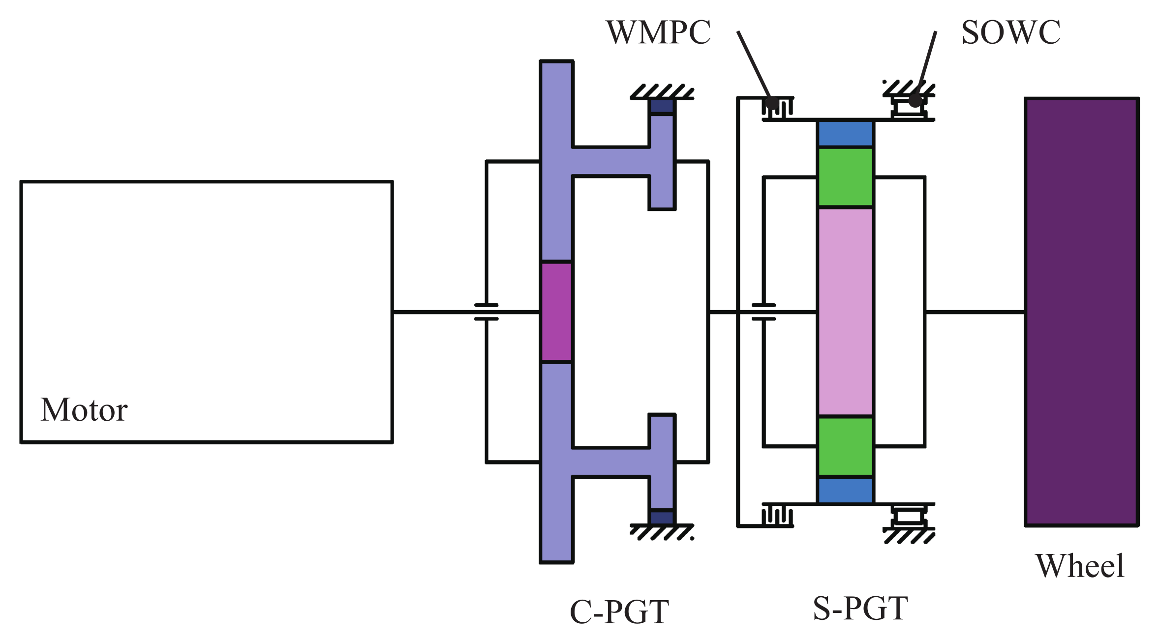
To minimize the unsprung mass and improve the reliability of the drive system, we adopt a miniaturized high-speed drive motor. In addition, given the limited design space in the wheel and the high likelihood of interference between the transmission system and the steering and braking systems, the gear transmission unit must have strict design requirements. Considering the above problems, we use two-stage planetary gear trains as the transmission unit. A block diagram of IW-AMT and the planetary gear train are shown in Figure 1 and Figure 2, respectively.
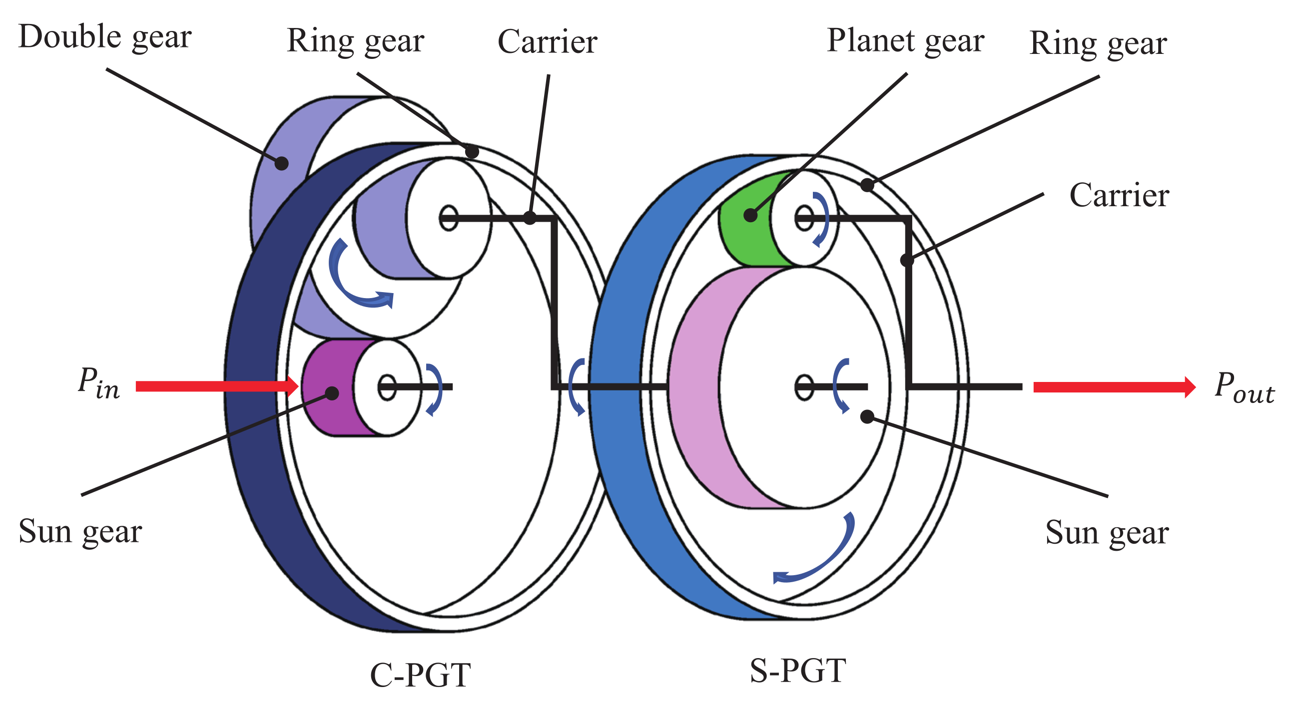
As shown in Figure 2, we use a compound planetary gear train (C-PGT) composed of a sun gear, three double planetary gears mounted on the carrier, and ring gear to realize the first deceleration stage [18]. The sun gear meshes with the larger planet gears, and the ring gear meshes with the smaller planet gears. The driving motor power is input through the sun gear and output by the carrier of C-PGT. The C-PGT realizes a large fixed transmission ratio with less mass and packaging space.
where is the pitch linear velocity of the large planet gear and the sun gear, and and are the radius and rotational speed of the sun gear, respectively.
Because the ring gear is fixed on the house rigidly, the contact point between the ring gear and the small planet gear has zero velocity, and the output velocity of the carrier can be expressed as follows:
where and denote the radii of the large and small planets, respectively, and is the rotational speed of the carrier.
The transmission ratio of C-PGT can be given as follows:
The other planetary gear set is a simple planetary gear train (S-PGT) composed of a sun gear, three planet gears, a carrier, and a ring gear. The power of the first stage is input to the sun gear and outputs to the wheel through the carrier. The S-PGT can achieve two gear ratio changes based on the action of the shift actuator. When the ring gear is fixed, the S-PGT further decelerates the drive motor. At this time, the reduction ratio can be calculated as follows:
where and denote the rotational speeds of the sun gear and carrier, respectively, and and denote the radii of the ring gear and sun gear.
When the sun gear and ring gear are combined, the S-PGT rotates at the same speed, and at this time,
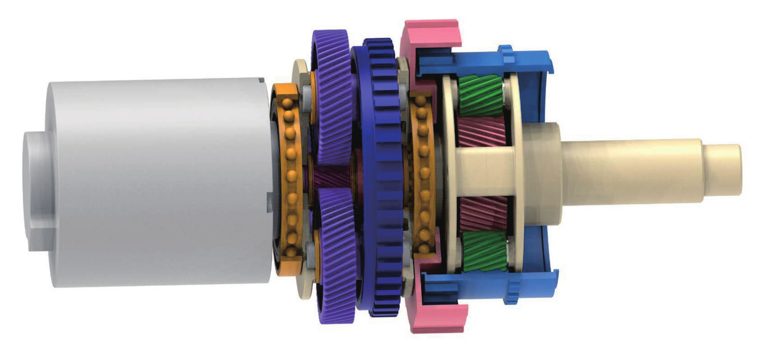
The structure of the planetary gear train is shown in Figure 3.
2.2. Selectable One-Way Clutch
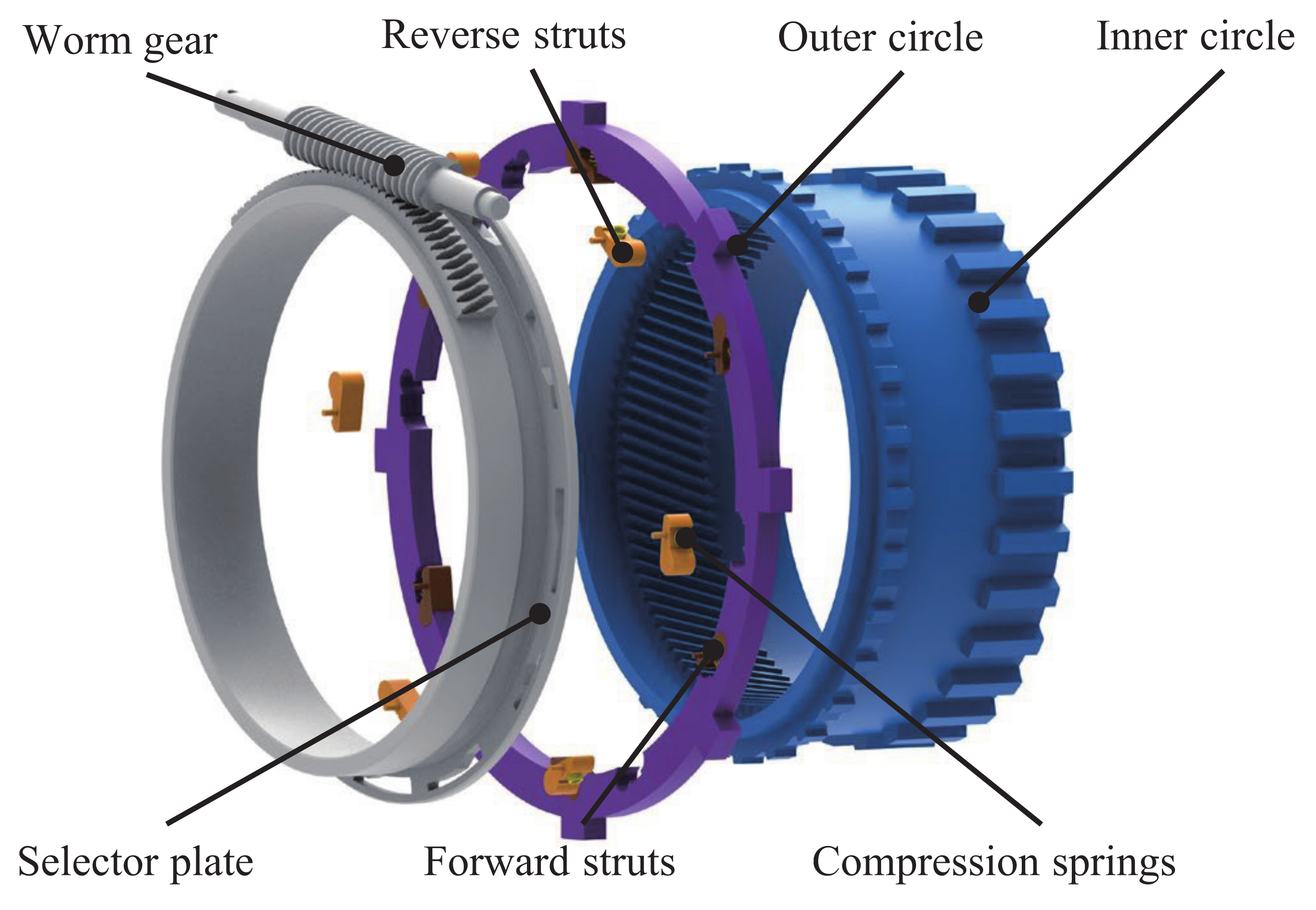
The SOWC was developed from OWC, and its basic operation is similar to that of OWC. By adding an independent control selection mechanism based on OWC, the selective output of power is realized. The SOWC can transmit power in two directions between the driving and the driven part, in addition to allowing for overrun in two directions. Moreover, it can effectively improve the transmission efficiency and reduce the unsprung mass, and it requires less packaging space. In the IW-AMT, the SOWC is used to reliably transmit power in both the first and reverse gears, and it is overrun in the second and neutral gears. The structure of SOWC is shown in Figure 4.
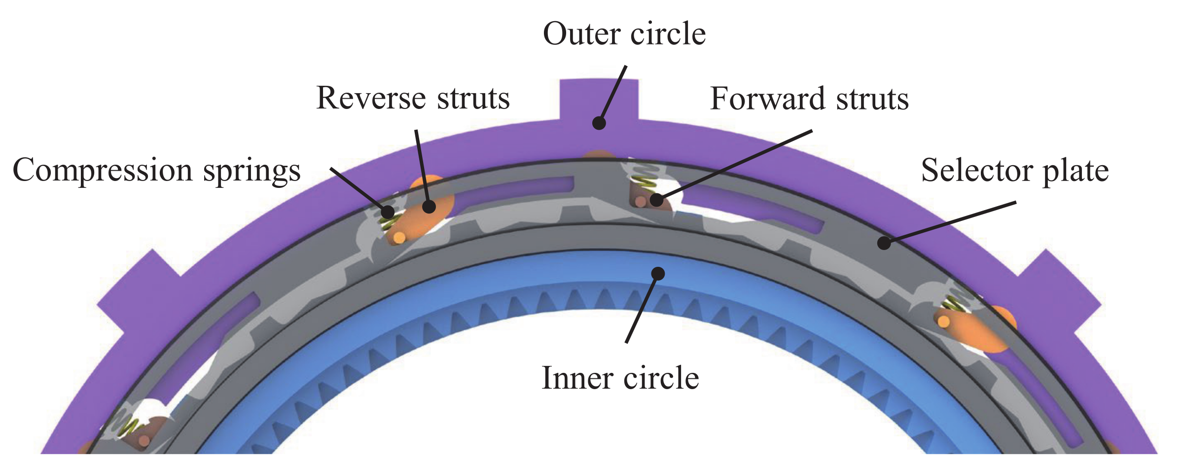
As shown in Figure 4, the SOWC is composed of an inner circle, an outer circle, reverse struts, compression springs, a selector plate, forward struts, and a worm gear [18]. The outer circle is fixed on the knuckle, struts are installed in the groove of the outer circle, and control pins on the struts are installed in the evenly arranged chute on the selector plate. The selector plate is fixedly connected to the worm gear mechanism, compression springs are installed between the struts and the outer circle, and the inner circle is fixedly connected with the ring gear of the S-PGT. As the worm gear mechanism rotates by the executive motor, the selector plate is driven to rotate, and the struts are up or down. The ring gear of the S-PGT is selectively locked in two directions or in a state of overrun. To show the working status of IW-AMT with SOWC in different gears clearly, we have developed the shift table, as shown in Table 1.
As shown in Figure 5, when the EV is engaged in the first gear, the selector plate rotates to drop the forward and reverse struts sequentially. The SOWC locks the ring gear of the S-PGT in the forward and reverse rotation directions and maintains the drive motor power output in the first gear ratio. When the drive motor is driving, the forward struts transmit the positive torque. When the motor instantly switches the braking state, the reverse struts transmit the reverse torque completely. There is no switching time between forward and reverse struts when the drive motor is cyclically switched between the driving and braking states. In the reverse gear, the state of the struts is the same as that of the first gear. The rotation direction and transmitted torque direction of each component are opposite.
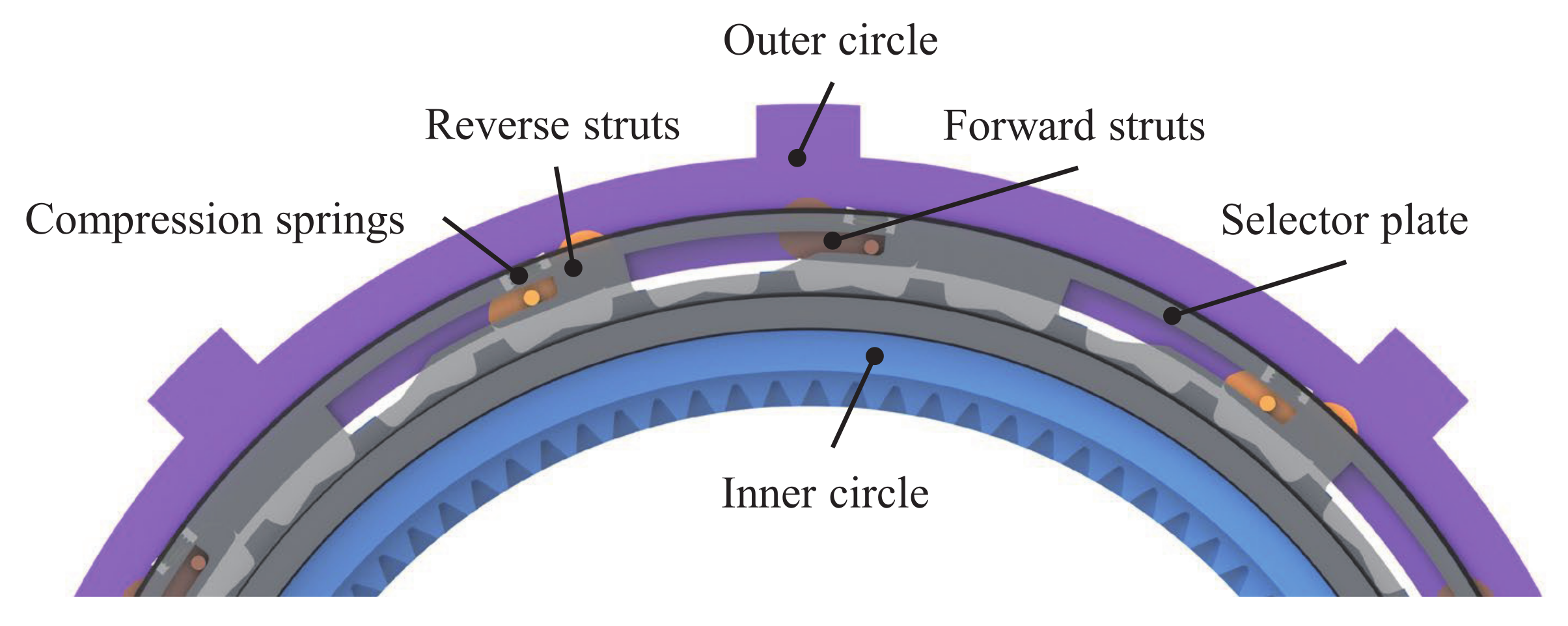
When the vehicle is in the second or the neutral gear, the SOWC is overrunning. By reasonably designing the selector plate chute, the forward and the reverse struts can be maintained in a raised state. At this time, the ring gear of the S-PGT is in a free rotation state. The corresponding schematic diagram is shown in Figure 6.
During upshifting, the selector plate rotates to sequentially raise the reverse and forward struts, so that the SOWC is overrunning. Conversely, during downshifting, the selector plate rotates to sequentially drop the forward and reverse struts, so that the SOWC locks the ring gear of the S-PGT in both directions. The schematic diagram of the intermediate state is shown in Figure 7.
2.3. Overall Structure and Characteristics
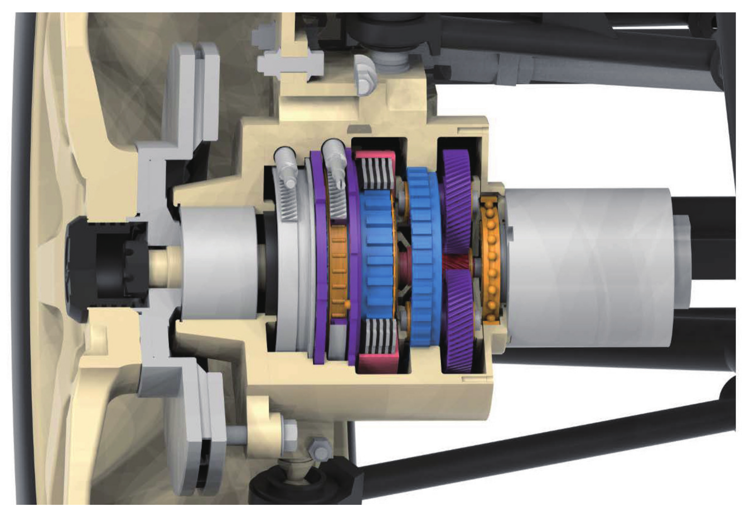
Through coordinated control of the drive motor and the shift actuators, the IW-AMT can achieve a variety of power output states. The structure of the IW-AMT is depicted in Figure 8, and the main technical parameters of the IW-AMT and NSK Ltd. wheel hub motor are summarized in Table 2. NSK Ltd. (Tokyo, Japan) adopts a dual-motor design, also with a two-stage planetary gear train. In contrast, the IW-AMT has a lower unsprung mass and higher power density.
3. Gear Shifting Process
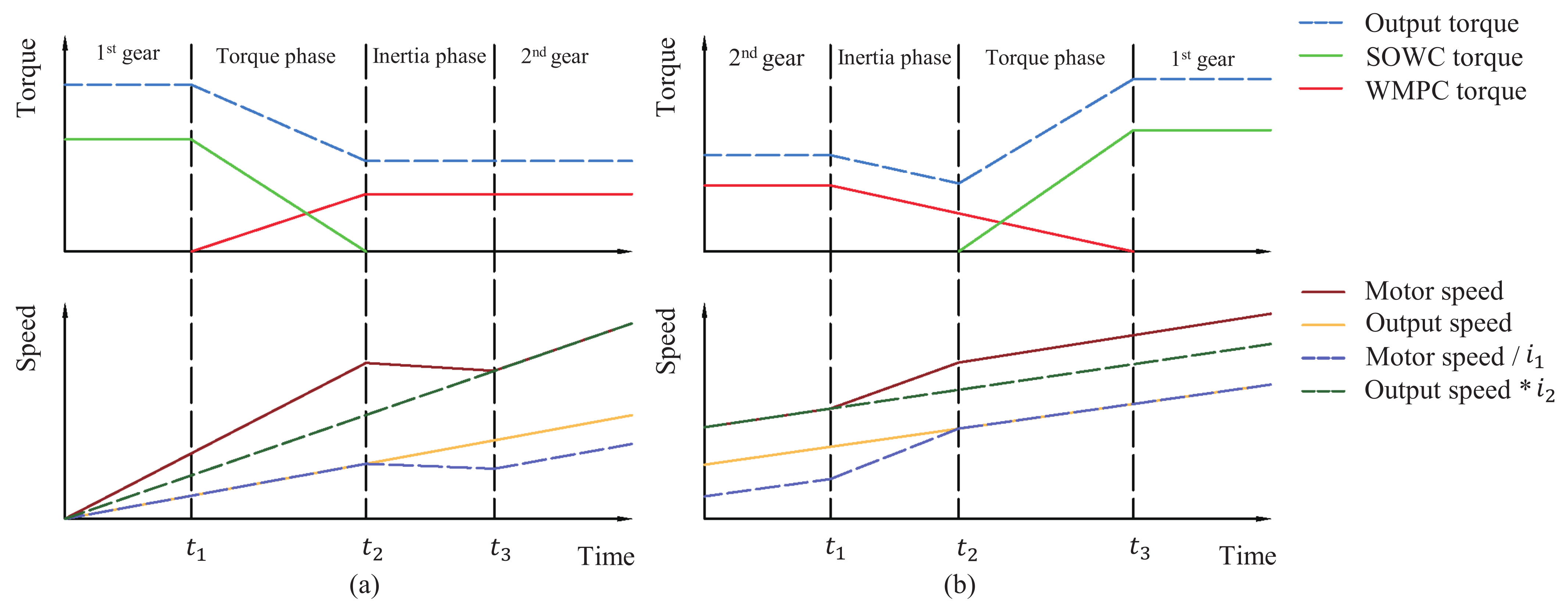
The IW-AMT entire gear shifting process includes the torque and the inertia phases [18]. The torque phase represents the phase of torque exchange during gear shifting. In the torque phase, the motor speed does not change suddenly, and the torque transmitted by each component is mutually exchanged. The torque phase ends when the torque synchronization is completed. The inertia phase represents the synchronization phase of the drive and driven components during the shifting process. In the inertia phase, there is no mutual exchange of torque, and the speed difference between the driving and the driven part of the clutch is gradually synchronized. The inertia phase ends when there is no speed difference in the clutch. The ideal shifting process of IW-AMT is shown in Figure 9.
During upshifting, the WMPC starts to combine, marking the start of the torque phase. With the gradual combination of the WMPC, the torque transmitted increases gradually, and the torque that the SOWC transmits decreases gradually. When the torque transmitted by the SOWC decreases to zero, the torque phase ends, and the inertia phase starts. At this time, the selector plate rotates, and the forward and reverse struts of the SOWC are raised sequentially. When the inertia phase starts, there is a speed difference between the driving part and the driven part of the WMPC. As the sliding grinding process continues, when the speed difference between the driving and the driven parts gradually decreases to zero, the inertia phase ends, and the EV starts to drive stably in the second gear.
During downshifting, the IW-AMT first enters the inertia phase, WMPC starts to separate gradually and enters a slipping state, and its transmission torque gradually decreases. As the speed difference between the driving and the driven parts of the WMPC gradually increases, the ring gear of the S-PGT decelerates gradually by the resistance torque. The inertia phase ends when the rotational speed of the ring gear is zero. At this time, the selector plate rotates and the SOWC forward and reverse struts are dropped sequentially, and the drive system enters the torque phase. As the WMPC continues to separate, its transmission torque further decreases, and the SOWC transmission torque gradually increases. The torque phase ends when the WMPC transmission torque decreases to zero, and the EV starts to drive stably in the first gear.
4. Simulation Model and Results
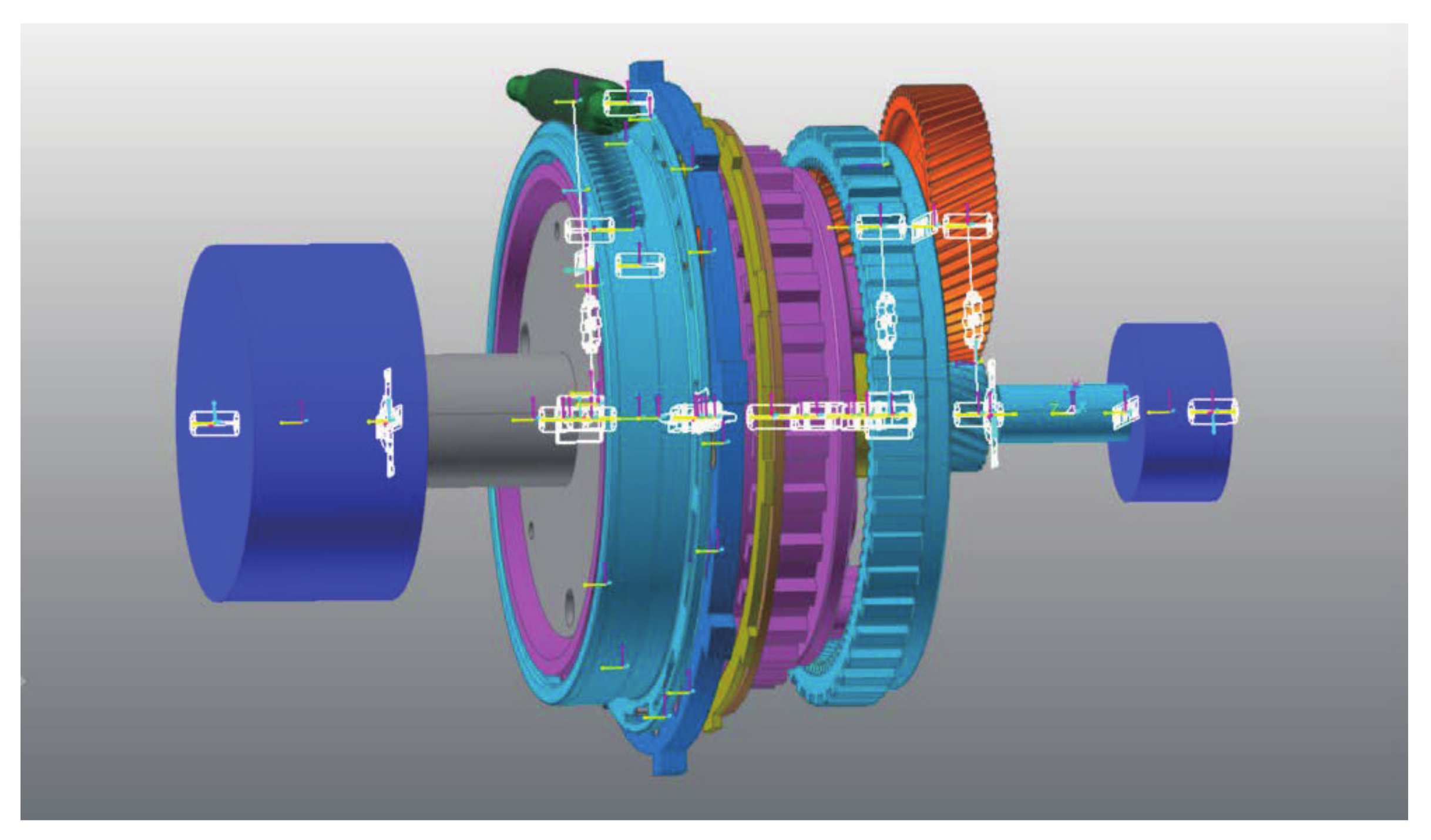
To clearly depict the changes in the torque and speed of each component of the IW-AMT system with the SOWC during the gear shifting process and evaluate the quality of shifting, we established a virtual prototype simulation model of the IW-AMT. The simulation model was composed of the motor and vehicle equivalent model, two-stage planetary gear train model, and SOWC model, including outer circle, inner circle, worm gear, selector plate, struts, and compression springs. The virtual prototype simulation model is shown in Figure 10, and the main parameters are summarized in Table 3.
In the virtual prototype simulation model, we modeled the motor as a rigid body whose rotational inertia is . At the output end of the simulation model, we constructed a cylindrical rigid body to simulate the equivalent inertia of the vehicle. The vehicle resistance torque includes the rolling resistance torque , air resistance torque , acceleration resistance torque , and ramp resistance torque . The vehicle resistance torque was applied to the output terminal to simulate changes in the resistance torque during driving.
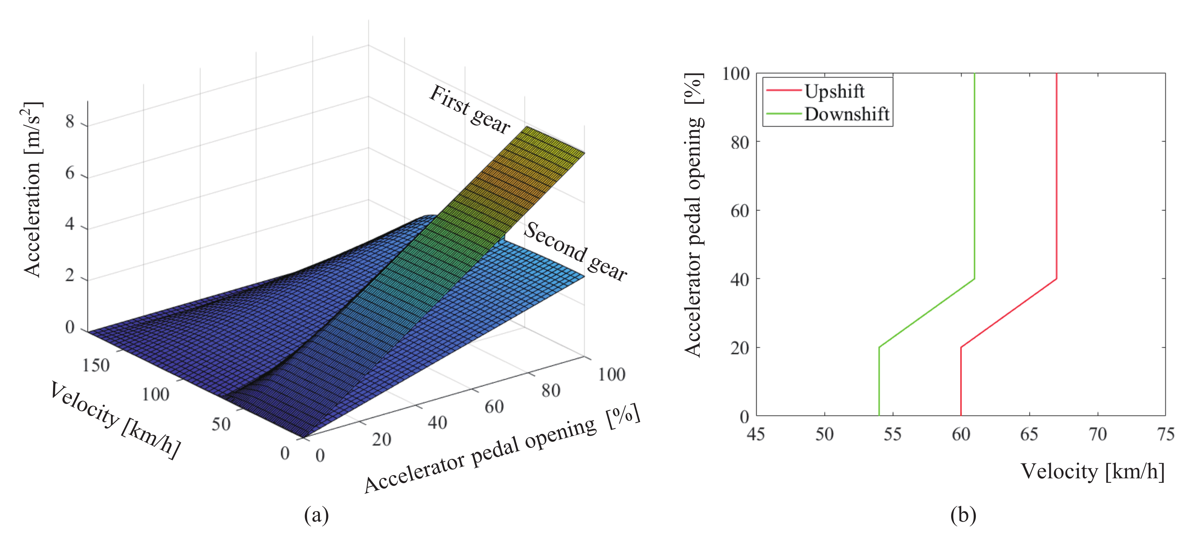
To improve vehicle dynamics and make full use of motor power. We designed a dynamic dual-parameter shifting schedule, as shown in Figure 11, taking the intersection of the vehicle acceleration curves at different accelerator pedal openings in two adjacent gears as the shifting point. To avoid frequent shifts near the shift speed, we delayed the downshift curve by 6 km/h.
The jerk of the vehicle j is an important indicator for evaluating ride comfort, and the recommended value of Germany is 10 m/s [27]. In IW-AMT, the SOWC is used to transmit torque in the first and reverse gears, which does not have the gradual engaging process that a friction clutch does.Therefore, we select the jerk as a criterion to evaluate the quality of shifting. During the shifting process, the jerk j can be expressed as:
where a and v denote the longitudinal acceleration and velocity of the vehicle.
Because we focus on the parameter changes of IW-AMT during the shifting process, the period time of the shifting process is intercepted and displayed in the simulation results.
4.1. Upshifting Process
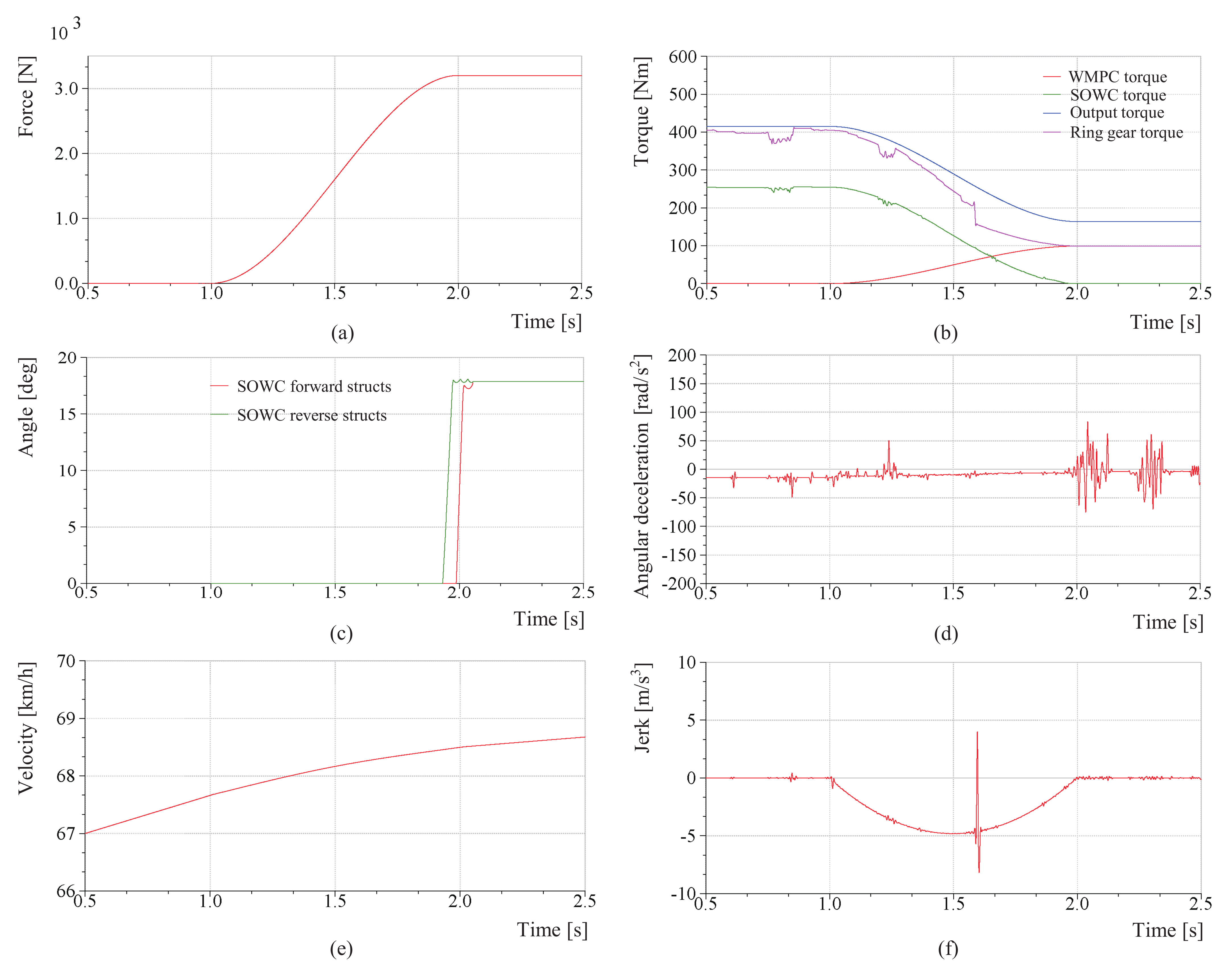
In the initial stage of the upshifting process, the SOWC forward and reverse struts are dropped to lock the ring gear of the S-PGT. With the gradual combination of the WMPC, the upshifting process starts. The simulation results are as follows:
As shown in Figure 12, when the upshifting process starts at 1 s, as the WMPC compression force gradually increases, its transmission torque increases gradually, and the transmission torque of the SOWC forward struts decreases gradually. At approximately 2 s, the SOWC transmission torque decreases to zero, forward and reverse struts are controlled to rise sequentially. The struts can be raised smoothly when the transmission torque of the ring gear is not decreased to zero, the switching time of the struts is about 0.04 s, and the forward strut’s lag behind the reverse struts is about 0.05 s. Throughout the upshifting process, the torque and the vehicle velocity change smoothly, without torque interruption, and the maximum jerk is less than 10 m/s.
4.2. Downshifting Process
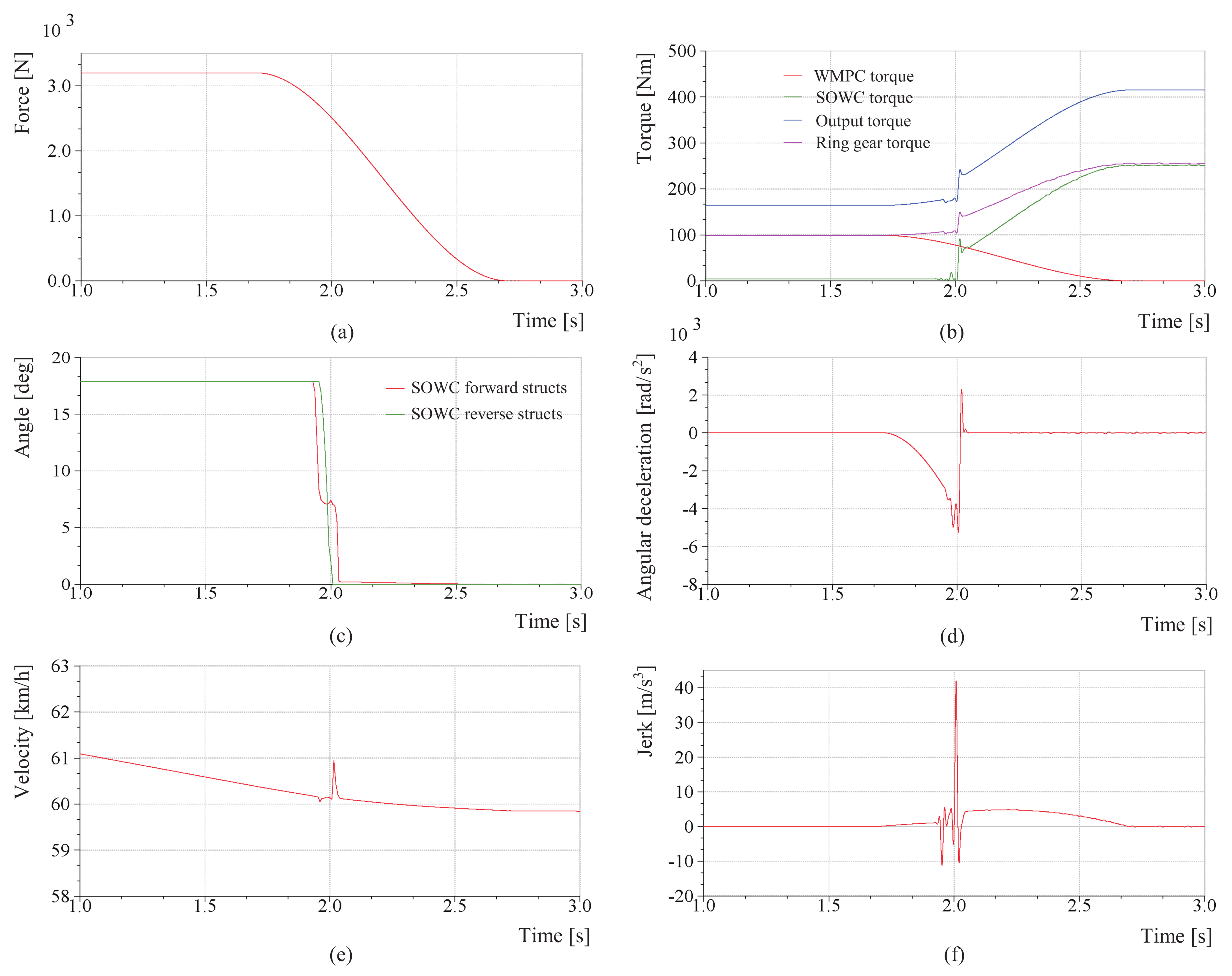
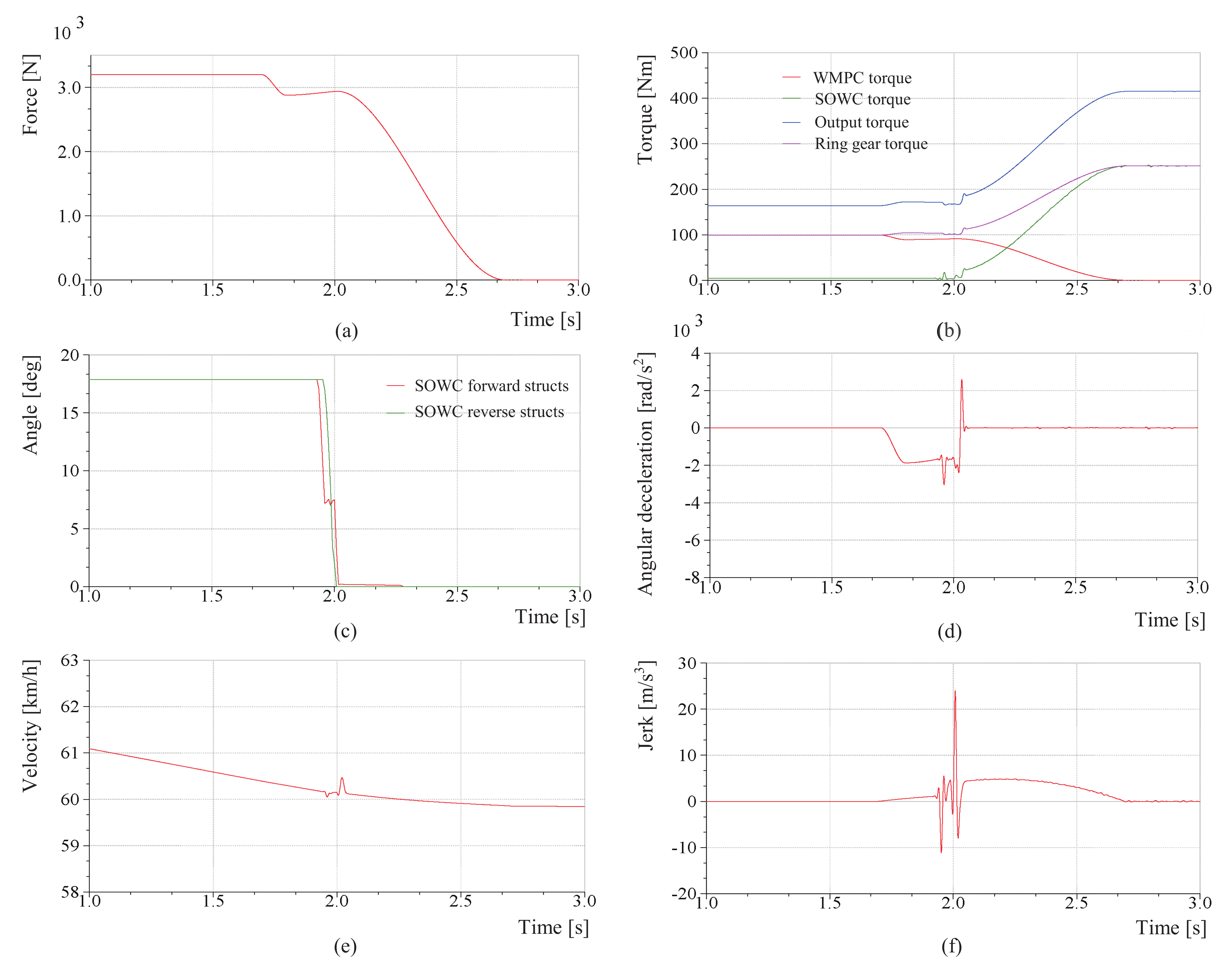
The downshifting process is basically the opposite of the upshifting process. In the initial stage of the downshifting process, the SOWC is overrunning, its forward and reverse struts are raised, and the WMPC is in a stable combined state. With the gradual separation of the WMPC, the downshifting process commences. To simulate the power downshift of the vehicle, we increase the ramp resistance torque to simulate the vehicle climbing condition for fulfilling the power downshift condition. The simulation results are as follows:
As shown in Figure 13, the downshifting process starts at approximately 1.7 s, and as the WMPC compression force decreases, the transmission torque gradually decreases. This causes the S-PGT ring gear to gradually reduce its rotational speed under the action of the resistance torque, and there is a tendency for reverse rotation. When the rotational speed of the ring gear decreases to zero, the SOWC forward and reverse struts are dropped sequentially. When the forward struts come into contact with the ring gear, the rotation angle curve fluctuates; at this time, the forward struts have locked the ring gear and then the reverse struts dropped smoothly. The reverse struts dropped behind the forward struts at about 0.05 s but dropped completely about 0.05 s earlier than the forward struts. At approximately 2.7 s, the WMPC is completely separated, all of the torque is transmitted by the SOWC. The torque fluctuation during the entire downshifting process is greater than that during the upshifting process. The maximum jerk is approximately 41 m/s, and part of the reason may be that the ring gear has a higher deceleration when the struts dropped.
4.3. Improvement of Jerk
To reduce the peak jerk of the vehicle during downshifting and improve ride comfort, we analyze the momentary state of the SOWC forward struts that are dropped during downshifting.
As can be seen from the previous simulation results, when the SOWC forward struts are dropped for approximately 2 s during the downshifting process, the vehicle torque fluctuates considerably. One of the reasons for this fluctuation is that the ring gear of the S-PGT decelerates to a greater extent when the WMPC gradually separates. When the SOWC forward struts are dropped, it resists deceleration and produces a jerk. Therefore, we start by reducing the deceleration of the ring gear to reduce the jerk when the struts are dropped. The IW-AMT shift process indicates that if the WMPC continues to transmit torque during the sliding process, the deceleration of the ring gear under the action of the resistance torque can be decreased, and in this manner, the jerk induced when the forward struts are dropped can be reduced. The improved WMPC compression force curve and downshift simulation results are as follows:
As shown in Figure 14, after the improvement of the WMPC combined curve, the jerk caused by the falling of the SOWC forward struts decreased. The torque and velocity of the vehicle during the downshifting process were relatively stable, and the peak jerk was significantly reduced. The maximum jerk was approximately 23 m/s. Furthermore, we started with the SOWC structure and attempted to improve it to reduce the jerk.
Many studies have indicated that reducing the freeway angle of the SOWC is beneficial for reducing the jerk when the struts are dropped [28], but owing to the size limitation of the SOWC structure, the potential for improvement of the freeway angle is small. The SOWC freeway angle designed in this paper was 2°.
where is the freeway angle, a the number of struts grouping, n the number of struts, and z the number of teeth in the inner circle.
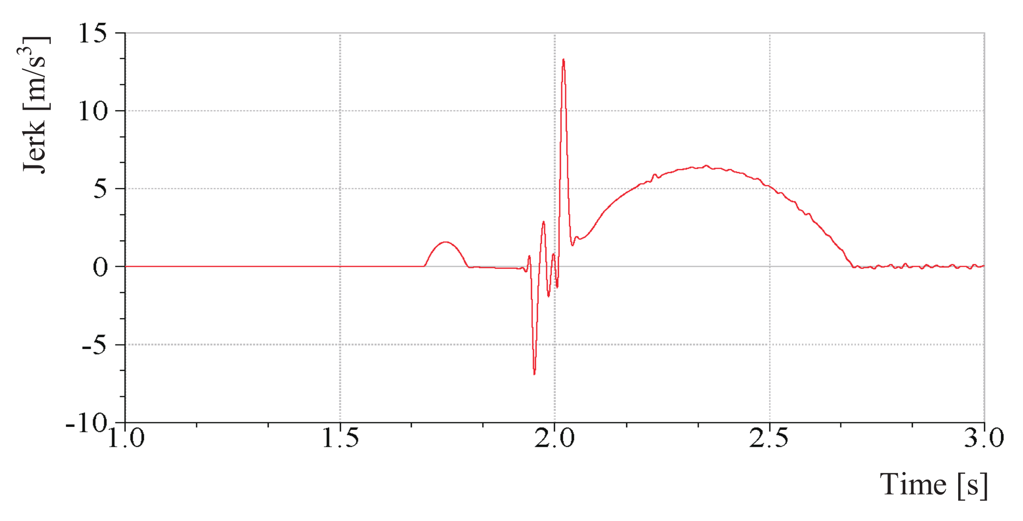
Furthermore, we refer to the principle of engine corner cushion cushioning and try to arrange a cushion with a certain stiffness and damping on the outer circle of the SOWC to alleviate the instantaneous impact when the SOWC forward struts are dropped. The stiffness coefficient of the cushion is 693.595 N/mm, and the damping coefficient is 0.466 N/(mm/s). The simulation results are shown in Figure 15, where the maximum jerk is approximately 13 m/s. The simulation results show that the placement of cushions has a significant effect on reducing impact.
5. Discussion
The simulation results of the upshifting process indicated that the vehicle speed and torque changed smoothly, and the jerk was less than 10 m/s. The was ascribed to the fact that the SOWC struts do not drop instantly during the upshifting process, and the magnitude of jerk is strongly related to the WMPC combination curve. The simulation results of the downshifting process indicated that when the WMPC separation curve was opposite to the combined curve, the impact of the jerk was approximately 41 m/s, and the shift impact was obvious. This is because the SOWC forward struts must drop during the downshifting process to instantly lock the ring gear of the S-PGT. Then, we start from the instantaneous state of the SOWC. After we improved the WMPC separation curve, the vehicle torque, and speed changed more smoothly, and the jerk was approximately 23 m/s, which represented a certain decrease but was nevertheless higher than the 10 m/s recommended value of Germany. Furthermore, we improved the SOWC structure by imitating the principle of engine corner pads and evenly arranged cushion rubber pads on the SOWC outer circle. Thereafter, the simulation results indicated that the jerk due to downshifting was approximately 13 m/s, since the SOWC does not follow a continuous process of combination and separation as in the case of the WMPC.
6. Conclusions
In this paper, we proposed an in-wheel two-speed AMT to improve the efficiency of the drive system and vehicle performance. In addition, to develop an efficient and compact drive system, we described the use of a SOWC as a new clutch solution for the IW-AMT. The mass of the proposed IW-AMT is only 15.72 kg, and its power and torque densities can be up to 2.23 kW/kg and 39.44 Nm/kg, and it effectively reduces the unsprung mass of the distributed in-wheel drive.
In future works, we will use relevant optimization theories to track and optimize the combination and separation curves of the WMPC to achieve the best shift effect with the SOWC.
Author Contributions
Conceptualization, D.M. and B.G.; methodology, Y.W.; software, D.M.; validation, D.M., F.W. and B.G.; writing—original draft preparation, D.M.; writing—review and editing, D.M. and B.G.; visualization, D.M.; supervision, B.G. All authors have read and agreed to the published version of the manuscript.
Funding
This research was funded by the National Nature Science Foundation of China No. 61803173, in part by Jilin Provincial Science, Technology Department No. 20200301011RQ, and in part by the Jilin Provincial Science Foundation of China under Grant 20200201062JC.
Acknowledgments
We acknowledge the members of Qingdao Legee Transmission System Technology Co., Ltd. for their support.
Conflicts of Interest
The authors declare no conflict of interest.
References
- Ding, N.; Prasad, K.; Lie, T.T. The electric vehicle: A review. Int. J. Electr. Hybrid Veh. 2017, 9, 49–66. [Google Scholar] [CrossRef]
- Grunditz, E.A.; Thiringer, T.; Saadat, N. Acceleration, drive cycle efficiency, and cost tradeoffs for scaled electric vehicle drive system. IEEE Trans. Ind. Appl. 2020, 56, 3020–3033. [Google Scholar] [CrossRef]
- Mo, W.; Walker, P.D.; Fang, Y.; Wu, J.; Ruan, J.; Zhang, N. A novel shift control concept for multi-speed electric vehicles. Mech. Syst. Signal Process. 2018, 112, 171–193. [Google Scholar] [CrossRef]
- Ahssan, M.R.; Ektesabi, M.M.; Gorji, S.A. Electric vehicle with multi-speed transmission: A review on performances and complexities. SAE Int. J. Altern. Powertrains 2018, 7, 169–182. [Google Scholar] [CrossRef]
- Rimpas, D.; Chalkiadakis, P. Electric vehicle transmission types and setups: A general review. Int. J. Electr. Hybrid Veh. 2021, 13, 38–56. [Google Scholar] [CrossRef]
- Montazeri-Gh, M.; Pourbafarani, Z. Simultaneous design of the gear ratio and gearshift strategy for a parallel hybrid electric vehicle equipped with AMT. Int. J. Veh. Des. 2012, 58, 291–306. [Google Scholar]
- Gao, B.; Liang, Q.; Xiang, Y.; Guo, L.; Chen, H. Gear ratio optimization and shift control of 2-speed I-AMT in electric vehicle. Mech. Syst. Signal Process. 2015, 50, 615–631. [Google Scholar] [CrossRef]
- Cui, J.; Tan, G.; Tian, Z.; Agyeman, P. Parameter Optimization of Two-Speed AMT Electric Vehicle Transmission System. SAE Tech. Pap. 2020. [Google Scholar] [CrossRef]
- Tian, Y.; Ruan, J.; Zhang, N.; Wu, J.; Walker, P. Modelling and control of a novel two-speed transmission for electric vehicles. Mech. Mach. Theory 2018, 127, 13–32. [Google Scholar] [CrossRef]
- Fang, S.; Song, J.; Song, H.; Tai, Y.; Li, F.; Nguyen, T.S. Design and control of a novel two-speed uninterrupted mechanical transmission for electric vehicles. Mech. Syst. Signal Process. 2016, 75, 473–493. [Google Scholar] [CrossRef]
- Yue, H.; Zhu, C.; Gao, B. Fork-less two-speed I-AMT with overrunning clutch for light electric vehicle. Mech. Mach. Theory 2018, 130, 157–169. [Google Scholar] [CrossRef]
- Feng, S.; Magee, C.L. Technological development of key domains in electric vehicles: Improvement rates, technology trajectories and key assignees. Appl. Energy 2020, 260, 114264. [Google Scholar] [CrossRef]
- Kim, D.; Shin, K.; Kim, Y.; Cheon, J. Integrated design of in-wheel motor system on rear wheels for small electric vehicle. World Electr. Veh. J. 2010, 4, 597–602. [Google Scholar] [CrossRef] [Green Version]
- Jian, L. Research status and development prospect of electric vehicles based on hub motor. In Proceedings of the 2018 China International Conference on Electricity Distribution (CICED), Tianjin, China, 17–19 September 2018; pp. 126–129. [Google Scholar]
- de Carvalho Pinheiro, H.; Galanzino, E.; Messana, A.; Sisca, L.; Ferraris, A.; Airale, A.G.; Carello, M. All-Wheel Drive Electric Vehicle Modeling and Performance Optimization. SAE Tech. Pap. 2020. [Google Scholar] [CrossRef]
- Gunji, D.; Matsuda, Y.; Kimura, G. Wheel Hub Motor. U.S. Patent 8,758,178, 24 June 2014. [Google Scholar]
- Wang, W.; Chen, X.; Wang, J. Motor/generator applications in electrified vehicle chassis—A survey. IEEE Trans. Transp. Electrif. 2019, 5, 584–601. [Google Scholar] [CrossRef]
- Meng, D.; Tian, M.; Miao, L.; Wang, Y.; Hu, J.; Gao, B. Design and modeling of an in-wheel two-speed AMT for electric vehicles. Mech. Mach. Theory 2021, 163, 104383. [Google Scholar] [CrossRef]
- Kim, J.; Choi, S.B. Design and modeling of a clutch actuator system with self-energizing mechanism. IEEE/ASME Trans. Mechatron. 2010, 16, 953–966. [Google Scholar] [CrossRef]
- Kim, D.H.; Kim, J.W.; Choi, S.B. Design and modeling of energy efficient dual clutch transmission with ball-ramp self-energizing mechanism. IEEE Trans. Veh. Technol. 2019, 69, 2525–2536. [Google Scholar] [CrossRef]
- Lee, C.J.; Samie, F.; Kao, C.K. Control of selectable one-way clutch in GM six-speed automatic transmissions. Dyn. Syst. Control Conf. 2009, 48937, 605–609. [Google Scholar]
- Bird, N.J.; Bindra, R.; Klaser, J. Development and challenges of electrically selectable one-way clutches. SAE Int. J. Engines 2017, 10, 1338–1350. [Google Scholar] [CrossRef]
- Xu, X.; Dong, P.; Liu, Y.; Zhang, H. Progress in automotive transmission technology. Automot. Innov. 2018, 1, 187–210. [Google Scholar] [CrossRef] [Green Version]
- Fan, Y. Study on the Transmission Characteristics of the Multi-gear Multi-degree-of-freedom Hybrid Planetary Gear Automatic Transmission Based on the Line Method. IOP Conf. Ser. Earth Environ. Sci. 2020, 512, 012168. [Google Scholar] [CrossRef]
- Beiser, C. Compact and Efficient Electric Propulsion Systems Enabled by Integrated Electric Controllable Clutches. In CTI Symposium 2018; Springer: Berlin/Heidelberg, Germany, 2020; pp. 20–42. [Google Scholar]
- Yamamoto, S.; Morita, R.; Oike, M. Transmission-equipped wheel hub motor for passenger cars. ATZ Worldw. 2018, 120, 28–33. [Google Scholar] [CrossRef]
- Yu, H.L.; Xi, J.Q.; Zhang, F.Q.; Hu, Y.H. Research on gear shifting process without disengaging clutch for a parallel hybrid electric vehicle equipped with AMT. Math. Probl. Eng. 2014, 2014, 985652. [Google Scholar] [CrossRef]
- Samie, F.; Lee, C.J.; Pawley, B. Selectable one-way clutch in GM’s RWD 6-speed automatic transmissions. SAE Int. J. Engines 2009, 2, 307–313. [Google Scholar] [CrossRef]
Figure 1.
Block diagram of IW-AMT.

Figure 2.
Block diagram of the planetary gear train.

Figure 3.
Structure of the planetary gear train.

Figure 4.
Structure of SOWC.

Figure 5.
Schematic diagram of the first and reverse gears.

Figure 6.
Schematic diagram of the second and neutral gears.

Figure 7.
Schematic diagram of the intermediate state.

Figure 8.
Structure of IW-AMT.

Figure 9.
Ideal shifting process of IW-AMT: (a) Upshifting process. (b) Downshifting process.

Figure 10.
Virtual prototype simulation model of IW-AMT.

Figure 11.
Dynamic dual-parameter shifting schedule: (a) Vehicle acceleration curves in different gears. (b) Upshift and downshift curves.
Figure 11.
Dynamic dual-parameter shifting schedule: (a) Vehicle acceleration curves in different gears. (b) Upshift and downshift curves.

Figure 12.
Simulation results of the upshifting process: (a) Changes of WMPC pressing force. (b) Changes in torque transmitted by each component. (c) Changes of struts rotation angle. (d) Changes of ring gear angular deceleration. (e) Changes in vehicle speed. (f) Changes in jerk.
Figure 12.
Simulation results of the upshifting process: (a) Changes of WMPC pressing force. (b) Changes in torque transmitted by each component. (c) Changes of struts rotation angle. (d) Changes of ring gear angular deceleration. (e) Changes in vehicle speed. (f) Changes in jerk.

Figure 13.
Simulation results of the downshifting process: (a) Changes of WMPC pressing force. (b) Changes in torque transmitted by each component. (c) Changes of struts rotation angle. (d) Changes of ring gear angular deceleration. (e) Changes in vehicle speed. (f) Changes in jerk.
Figure 13.
Simulation results of the downshifting process: (a) Changes of WMPC pressing force. (b) Changes in torque transmitted by each component. (c) Changes of struts rotation angle. (d) Changes of ring gear angular deceleration. (e) Changes in vehicle speed. (f) Changes in jerk.

Figure 14.
Simulation results of the downshifting process after the improvement of the WMPC combined curve: (a) Changes of WMPC pressing force. (b) Changes in torque transmitted by each component. (c) Changes of struts rotation angle. (d) Changes of ring gear angular deceleration. (e) Changes in vehicle speed. (f) Changes in jerk.

Figure 15.
Jerk change during the downshifting process after the improvement of the SOWC structure.


Table 1.
Shift table of IW-AMT.
| Gear State | Motor Rotation Direction | SOWC Forward Struts State | SOWC Reverse Struts State | WMPC State |
|---|---|---|---|---|
| Neutral | - | Up | Up | Disengaged |
| First gear | Forward | Down | Down | Disengaged |
| Second gear | Forward | Up | Up | Engaged |
| Reverse | Reverse | Down | Down | Disengaged |
Table 2.
Comparison of the main technical parameters.
| Parameter | IW-AMT | NSK Ltd. Wheel Hub Motor [26] | Unit |
|---|---|---|---|
| Maximum output power | 35 | 25 | kW |
| Maximum output torque | 620 | 850 | Nm |
| Overall mass | 15.72 | 32 | kg |
| Power density | 2.23 | 0.78 | kW/kg |
| Torque density | 39.44 | 26.56 | Nm/kg |
Table 3.
Main parameters of the simulation model.
| Parameter | Value | Unit |
|---|---|---|
| Vehicle mass | 1036 | kg |
| Tire radius | 0.2979 | m |
| Vehicle frontal area | 1.4 | m |
| Air resistance coefficient | 0.45 | - |
| Rolling resistance coefficient | 0.011 | - |
| Rotation mass correction coefficient | 1.04 | - |
| Max motor torque | 21 | Nm |
| Max motor speed | 20,000 | rpm |
| Motor rotational inertia | 2.74 | kgcm |
| First gear ratio | 29.51 | - |
| Second gear ratio | 11.88 | - |
| Equivalent vehicle rotational inertia | 107.74 | kgm |
| Worm gear ratio | 35 | - |
| Worm gear drive speed | 334 | rpm |
| SOWC strut mass | 31.4 | g |
| Compression spring stiffness coefficient | 2.81 | N/mm |
Publisher’s Note: MDPI stays neutral with regard to jurisdictional claims in published maps and institutional affiliations. |
© 2021 by the authors. Licensee MDPI, Basel, Switzerland. This article is an open access article distributed under the terms and conditions of the Creative Commons Attribution (CC BY) license (https://creativecommons.org/licenses/by/4.0/).
Share and Cite
MDPI and ACS Style
Meng, D.; Wang, F.; Wang, Y.; Gao, B. In-Wheel Two-Speed AMT with Selectable One-Way Clutch for Electric Vehicles. Actuators 2021, 10, 220. https://0-doi-org.brum.beds.ac.uk/10.3390/act10090220
AMA Style
Meng D, Wang F, Wang Y, Gao B. In-Wheel Two-Speed AMT with Selectable One-Way Clutch for Electric Vehicles. Actuators. 2021; 10(9):220. https://0-doi-org.brum.beds.ac.uk/10.3390/act10090220
Chicago/Turabian StyleMeng, Dele, Fei Wang, Yuhai Wang, and Bingzhao Gao. 2021. "In-Wheel Two-Speed AMT with Selectable One-Way Clutch for Electric Vehicles" Actuators 10, no. 9: 220. https://0-doi-org.brum.beds.ac.uk/10.3390/act10090220
Note that from the first issue of 2016, this journal uses article numbers instead of page numbers. See further details here.