
Enhanced Oil Recovery Using CO2 in Alaska


Department of Petroleum Engineering, University of Alaska Fairbanks, 1764 Tanana Loop, Fairbanks, AK 99775, USA
*
Author to whom correspondence should be addressed.
Geosciences 2021, 11(2), 98; https://0-doi-org.brum.beds.ac.uk/10.3390/geosciences11020098
Submission received: 8 January 2021
/
Revised: 6 February 2021
/
Accepted: 8 February 2021
/
Published: 19 February 2021
(This article belongs to the Special Issue Mechanical Integrity of CO2 Storage Sites)
Abstract
:Alaska holds more than 68 billion barrels of proved oil reserves and more than 36.7 trillion cubic feet of proved natural gas reserves with some special conditions such as proximity to permafrost, making Alaskan petroleum reserves unique. The low temperature in shallow reservoirs prohibited hydrocarbons’ ideal maturation, thereby generating several heavy and viscous oil accumulations in this state. This also limits the enhanced oil recovery (EOR) options, leaving the thermal methods off the table to avoid permafrost thawing, which can cause wellbore collapse. Several solutions have been attempted for improving oil production from heavy and viscous oil in Alaska; however, they have not yielded the desired recovery, and ultimate recovery factors are still less than the global average. One solution identified as a better alternative is using CO2 as an injecting fluid, alternated by water or mixed with other injectants. This paper provides a comprehensive overview of all studies on using CO2 for enhanced oil recovery purposes in Alaska and highlights common and unique challenges this approach may face. The suitability of CO2-EOR methods in the Alaskan oil pools is examined, and a ranking of the oil pools with publicly available data is provided.
1. Introduction
Alaska has a 68 billion barrel reserve of original oil-in-place, with about 13.7 billion barrels recoverable by primary and secondary recovery methods and 36.7 trillion cubic feet of proved natural gas reserves [1,2]. Scientific assessments estimate an additional 24 billion barrels of oil and 103 trillion cubic feet of technically recoverable gas [3]. In the North Slope and Cook Inlet of Alaska, about 12.54 billion barrels of oil have been produced cumulatively until 2019 [4]. North Slope oil is occasionally characterized as a highly viscous oil with an unfavorable mobility ratio, which presents the challenge of low recovery from conventional waterflooding projects. Prudhoe Bay contains an additional 2.5 billion barrels of tertiary recoverable oil, plus a further 426 million in viscous oil reserves from satellite developments such as Orion, Polaris, and Midnight Sun [4]. Viscous oil recovery has been shown to be between 10% and 20% of OOIP as opposed to 35% to 40% in light oil reservoirs [2,5].
Although horizontal drilling has unlocked production from viscous oil reservoirs, waterflood recoveries are low, which necessitates advanced technology such as thermal, chemical or miscible gas EOR processes. However, these processes have their shortcomings [6]. Thermal methods are not feasible in Alaskan wells due to thick permafrost, high well costs, and large well spacing [7,8]. Chemical EOR techniques involve adding polymer molecules to water to increase water viscosity and reduce water mobility. Polymer flooding has historically been the go-to choice for unfavorable mobility reduction in enhanced oil-recovery techniques due to its simplicity and low operational cost [9,10]. The efficiency of polymer injectivity depends on polymer degradation and retention, impacting its transportation in porous media [11,12,13]. Hydroxyl ethyl cellulose (HEC) and sodium carboxyl-methyl cellulose are some natural polymers used in the flooding processes. Polyacrylamide (PAM), Hydrolyzed Polyacrylamide (HPAM), xanthan, and biological polysaccharides are the common types of synthetic polymers used in flooding procedures. HPAM has been used in the first-ever polymer flooding pilot program in Alaskan wells and has been shown to significantly delay breakthrough time and increase sweep efficiency [12].
Nanoparticle migration has presented permeability reduction by pore-throat plugging, slight sedimentation of nanoparticles, and accumulation of various sizes of nanoparticles in the pore throat. Polymer-nanoparticles-assisted models have been developed to control nanoparticle migration mobility in reservoirs, allowing permeability in water-swept zones to be improved dramatically [14].
Foam flooding has also been considered as one of the chemical methods to improve oil recovery [15,16]. Foam flooding improves volumetric sweep efficiency for the fluid in the solvent phase by reducing injected gas mobility, which is considered a technique for mobility control. [11]. A field trial in the Prudhoe Bay of Alaska in 1991, where foam was injected, yielded a significant reduction in GOR, translating into an increase in oil production for several weeks. It is worth mentioning that at the time, oil production was constrained by the amount of gas reinjection capability; therefore, oil production was prorated based on the well’s GOR. [17].
Other chemical EOR techniques involving using nonionic surfactants such as Zizyphus Spina Christi, anionic surfactant, and SDBS have been experimentally shown to change calcite, dolomite and quartz anhydrite wettability from oil wet to neutral-wet or slightly water-wet [18,19,20]. In a study on calcite, dolomite and quartz core plugs, oil recovery factors of 66%, 41%, and 93% were observed respectively, which is indicative of surfactant success in enhanced oil recovery techniques [18]. A synergic combination of surfactants and polymer flooding has been studied as a potential for EOR in Alaska with encouraging results [21].
Cyclic CO2 injection, also known as the huff-n-puff method, has been employed in shale formations due to hydraulic and natural fractures. This unique characteristic provides a large contact area for the injected gas to penetrate and diffuse in the rock matrix. The relatively short payback period of cyclic processes, and the use of a single well injector are some of the advantages of cyclic CO2 injection compared to other techniques [22,23]. It is important to understand the phenomena and parameters governing injectivity in a CO2 flooding program. How to vary these parameters for optimum injectivity and modify them in case of an injectivity loss, would determine oil recovery or CO2 storage capacity [24]. Fluid/rock interactions, transport mechanism, and geomechanical effects can potentially impact CO2 injectivity within any flooding or geological sequestration program. Understanding the impact of temperature, pressure, and carbon dioxide soaking time on carbon dioxide adsorption gives an idea of a target formation’s storage capacity [25]. Laboratory experiments of cyclic CO2 injection have shown shale oil recoveries of between 33% and 85% depending on the shale core type [22]. Huff-n-puff techniques have been primarily performed in shale formations in Alaska, although oil shale deposits in Alaska has been sparse, mainly in the Kandik province of central Alaska. [26].
For miscible gas EOR, miscibility is usually achieved by mixing lean gas with expensive NGL [2]. In the case of injecting NGL’s in the reservoir, large volumes required for enhanced recovery can be both impractical and uneconomic. However, miscible gas injection has been successfully applied as a field experiment in Alaska’s North Slope [6], albeit with logistical, technical, and economic limitations.
Furthermore, MMP between the viscous oils and conventional miscible injectants is too high for many viscous oils in the Alaskan North Slope [4]. Significant effort has been directed at CO2-EOR in Alaska, where CO2 has been used as a stimulant in a single well gas flooding process [27] or as a conventional viscosity reducing injectant in its pure or enriched form [1]. In the gas flooding process, injected CO2 displaced produced liquid previously occupying pore spaces. Some degree of mass or component transfer (dissolution of gas in residual oil or evaporation of light-oil component into injected gas phase) between oil and injected gas occurs [28]. The solubility of CO2 in hydrocarbons cause the reservoir liquids to swell, subsequently decreasing oil viscosity and improving mobility [29]. CO2 achieves miscibility at a pressure between 1040 psi to 4351 psi, reducing the interfacial tension between oil and water [30]. CO2-EOR and sequestration studies have been shown to decrease emissions into the atmosphere and have been an attractive option for oil and gas operators in Alaska [31]. Some reasons cited for successful CO2 flooding and sequestration project are increased oil revenue from CO2-EOR, the presence of an existing caprock with reliable integrity, data availability, and existing infrastructure [28].
Enhanced Oil Recovery (EOR) techniques, both actively employed in fields or purely experimental, have been studied in Alaska [27,30,31,32]. However, even with perfect design, several operational constraints limit options in this region. Handling sand production in arctic conditions [32], proximity to permafrost and the technical challenges permafrost poses on applying EOR techniques [33,34], high asphaltene content and low in-situ permeability [35], and finally, low net-to-gross sand ratio were some of the challenges that operators had to overcome in designing EOR programs. This paper reviews the current state of CO2-EOR projects in Alaska presents the ranking of CO2 field storage capacity and the potential of enhanced production from Alaskan oil fields.
2. Geology of Alaska
Alaska has been described as a jigsaw puzzle placed together over epochs of time as tectonic plates collide with each other [4]. Alaska is located between the arctic margins and the Cordilleran Orogenic Belt of western North America. The landmass was formed due to deformations involving oceanic plates, strike-slip faults, and subduction zones [36]. Metamorphic rocks, deformed under significant heat and pressure, create much of Alaska’s bedrock. Faults spatially separate these older metamorphic rocks, many of which are recently active and responsible for earthquakes and volcanoes can be classified into three groups: Metamorphosed continental margin rocks, metamorphosed marine, and marginal sedimentary rocks, and finally, the variably metamorphosed arc-related volcanic, oceanic, sedimentary and plutonic rocks of south-central and south-east Alaska [4].
Prominent tectonic features such as Subduction zones form along most of the Earth’s convergent plate boundaries and are responsible for large scale cycling of crust and fluid into the mantle. Evidence for petroleum generation is widespread in subduction-related basins, i.e., oil and gas seeps, hydrocarbon shows in petroleum exploration wells. Figure 1 shows the tectonically active regions that present evidence of forming favorable structural traps, folding, and faults beneficial for hydrocarbon accumulation. It is imperative to note that while the intensity of present-day tectonic events is abundant in the south of Alaska, most of the hydrocarbon accumulations are in the North Slope.
A synoptic view of Alaska and Western Canada’s neotectonics provides evidence of the relative motion between North America, Pacific, and Bering plates, which may be the source for many modern deformations, including basins and rifts, observed in Alaska [38]. Alaska has been prolific with significant mineral and hydrocarbon resources primarily due to its dynamic tectonism. The North American plate houses the Cook Inlet Basin, the Nenana Basin, and the North Slope Basin, which is classified as a major play for hydrocarbons in North America [39].
2.1. North Slope Sedimentary Basin
The North Slope sedimentary basin at the north of Alaska consists of two highly deformed Mississippian to earliest Cretaceous continental platform sequences and an overlying Quaternary successor basin sequence [40]. The rock sequence contains the Endicott, Lisburne, Shublik, and Sadlerochit groups [40]. A structural axis known as the east-plunging Barrow arch separates the foreland basin from the passive margin, where most oil and gas accumulations occur [41]. The North Slope aerially ranges from the northern slopes of the Brooks Mountain Range to the Arctic foothills [42]. The Brooks Range consists of rugged, linear mountain ranges at heights of 9900 ft eastward but decreases gradually towards the west [40]. The arctic foothills cover the marshy Arctic coastal plain and move progressively towards the arctic ocean [40]. The Shublik, Kingkak Shale, Pebble Shale Unit, and Torok formations have been shown through preliminary evaluation as the source rock of North Slope and are underlain by the west-trending Colville Basin [36,41].
2.2. Nenana Basin
The basin is located in the interio Alaska, and is filled with Cenozoic strata, including marine fluvial and lacustrine deposits of the Eocene to Miocene Usibelli Group, extending to depths of 25,000 ft to 30,000 ft. Coal intersperses the Usibelli Group, which is mined at the nearby town in Healy [43]. The Nenana Basin primarily contains the Pliocene Nenana Formation and the Miocene Usibelli Group. The Pliocene Nenana group comprises sandstone and claystone with interspersed shale, while the Miocene Usibelli Group comprises sandstone and conglomerate deposited in an alluvial system [43,44].
Gravity modeling [44] of the Nenana Basin area suggests that the most promising petroleum exploration area is a prominent 25 mGal isostatic gravity low north of Nenana. This location corresponds to the deepest part of the sedimentary basin. Low gas saturated sandstone reservoirs have been recently explored within the Minto-Nenana Basin. The Nenana Basin is estimated to hold between 150 billion to 180 billion cubic feet of natural gas [45].
2.3. Cook Inlet Basin
The Cook Inlet Basin, located at the south of Alaska, is famous for being the host of Alaska’s first commercial oil discovery in 1957, the Swanson River Field. The basin is characterized by tidal, alluvial, and glacial-fed deposition along the pacific plate between Kenai and Chugach mountains [46,47]. The Cook Inlet is composed mainly of Cenozoic and Tertiary formations, including the Sterling, Beluga, and Tyonek formations housing gas accumulations, and Tyonek, Hemlock, and West Foreland formations housing oil [46]. The Cook Inlet Basin folds into an anticline running from the northeast, dipping at an angle towards the southwest, mainly due to proximity to the plate boundaries [48]. Over a 200 million year period, subduction and associated arc magmatism have been responsible for deformations in this basin [49]. The Cook Inlet Basin consists of more than 18 km of Jurassic to Cenozoic deposits [50]. Nonmarine deposits dominate the Cenozoic Fill and are separated from the underlying Mesozoic units by a regional unconformity. These deposits are related to a spreading center’s subduction during the latest Cretaceous-Paleocene time [50,51]. Production from the Cook Inlet Basin peaked at 230,000 barrels per day (bpd) in 1970, fell to 8900 bpd in the 2010 fiscal year, but rebounded to 15,000 bpd in 2016 after tax policy reforms [52]. Table 1 presents a brief overview of the lithology, reservoir and fluid properties of the major oil fields in some sedimentary oil pools of Alaska.
3. Oil and Gas Production in Alaska and Its Future
The US Congress granted statehood to Alaska 2 years after oil was discovered at the Swanson River of the Cook Inlet Basin in 1957. However, the Prudhoe Bay oil field in the North Slope Basin found in 1967 established Alaska as a world-class oil and gas province. The North Slope alone is estimated to hold 22 billion barrels of oil, with 9.6 billion recoverable, and 124 trillion cubic feet (Tcf) of natural gas [7]. Using advanced drilling technologies and EOR techniques such as miscible gas injection, 13 million barrels of oil have been produced from Prudhoe Bay as of 2020, with potential for further production [52]. Figure 2 presents a snapshot of the production history of some oil pools in Alaska, including the Samson River, Hemlock oil which is still in production [55].
The National Petroleum Reserve of Alaska (NPR-A) holds an estimated 17.6 billion barrels of oil, and the assessment of the Arctic National Wildlife Refuge (ANWR) exhibited an estimate of 7.8 billion barrels of recoverable oil [71,72]. The Alaska Ocean Continental Shelf (OCS) is estimated to hold 19.09 billion barrels of oil and 96.76 Tcf of gas at a 95% probability [71].
After 40 years of production, operators in Alaska are pursuing novel ways to develop the remaining reserves, including heavy and viscous resources, remote oil fields, and gas hydrate resources. Oil production has dropped by approximately 75% since hitting a peak of about 2 million barrels per day in 1988. New field discoveries in the Cretaceous Nanushuk and Torok formations offer the potential for increased future production; however, the development of these resources is subject to final investment decisions of at least $11 billion [52]. An attractive option to increase oil recovery in the interim is to exploit the residual, viscous, and heavy oils in Alaska. Improving drilling technology and enhanced oil recovery techniques (EOR) are readily available options to achieve this goal.
3.1. EOR in Alaska
Previous waterflooding attempts in Prudhoe Bay yielded 10–20% of oil production after natural depletion and water flooding mechanisms [4]. During the diagenesis of oil, residual oil is trapped by capillary forces and is surrounded by water or gas occupying the larger pores [72]. In Prudhoe Bay and several projects in the USA and Canada, associated gases produced alongside oil are re-injected into the reservoir to recover part of the oil left behind [6]. Injection of the associated gases with reservoir oil reduces interfacial tension and facilitates the flow of trapped oil.
Table 2 presents an overview of EOR techniques studied and employed in Alaska. Cited articles attempted to address some specific reservoir challenges such as technical restrictions permafrost poses on thermal methods and the structural stability of production facilities, high asphaltene content, as well as sand production handling and control in remote arctic environments.
3.2. Polymer Flooding in Alaska
The use of polymer is investigated through an experimental polymer flooding pilot for EOR on heavy oils in ANS [12]. The technique combined polymer flooding, low salinity water flooding, horizontal wells, and occasional injection conformance control treatments as an integrated process. The pilot project acquired scientific knowledge and field performance data to optimize polymer flood design in the Shrader Bluff heavy oil reservoirs. Partially hydrolyzed polyacrylamide (HPAM) polymer was selected, and the initial target viscosity was set at 45 cP [13,73]. The injection pressure was controlled below or slightly higher than fracture pressure to prevent fracture extension, which caused early breakthrough (BT). Step rate and pressure falloff tests indicate that injectivity in the short-term is mostly controlled by fluid mobility deep in the reservoir and not in the vicinity of the wellbore. After nine months of observation from the start of polymer injection, no polymer was observed in the production stream as opposed to a 3-month breakthrough time with waterflood. This result is indicative of polymer significantly delaying breakthrough and increasing sweep efficiency [13,73].
3.3. Solvent-Based EOR in Alaska
Vapor Extraction Process (VAPEX) is considered for the West Sak and Ungu sands of Alaska North Slope. Numerical and experimental studies involving a novel, CT scanner-compatible experimental apparatus for probing vapor enhanced gravity drainage processes suggest a potential of 15–20% additional recovery over the life of the reservoir [74]. This heuristic study showed that although the saturation patterns observed throughout the entire process were uncorrelated, the vapor chamber showed gas segregation toward the top of the pack according to gravity A constant injection rate and a constant bottom hole pressure at the multi-lateral producer well, from an experimental standpoint, yields the longest BT time of the different tested injectants. The numerical modeling shows that 20% of asphaltene is produced, GOR increases after gas BT, and water production is negligible. The VAPEX project will require large volumes of injection solvent from horizontal injectors, affecting the project’s economic feasibility. The idea of nano-particle application as a solvent for EOR has been in its feature-reaction catalysis, reducing in-situ oil viscosity and generating emulsion without surfactant [75]. The nano-emulsion flooding can be a useful enhancement for an oil recovery method for a heavy oil reservoir, which is technically sensitive to the thermal recovery method [76].
3.4. Low Salinity Waterflood in Alaska
Coreflooding experiments to evaluate the potential of low salinity brine injection on EOR for ANS observed a consistent trend of reduction in residual oil saturation of up to 20%, and the Amott-Harvey Wettability Index slightly increased with a decrease in injected brine at reservoir temperature [34]. The salinity of the waterflood varied between 22 k total dissolved solids (TDS) and 55 k TDS. An advantage of Low Salinity Waterflooding (LoSal) is the ease with which it can be conducted in harsh operating environments as compared to other chemical EOR processes. LoSal projects do not require importing large volumes of chemicals and don’t require difficult surface handling and mixing facilities [35]. Controlling factors in the recovery of a LoSal waterflooding are rock lithology, oil chemistry, and brine salinity. These factors affect the reservoir wetting state and consequently, control the displacement of oil from reservoir rock [77]. LoSal waterflooding has shown significant improvement in the recovery factor by reducing the residual oil saturation (Sor) [35,80].
In a single-well chemical tracer test performed in the Ivishak Sandstone, Kuparuk, and Kekiktuk sandstones housing the Endicott oil, waterflood residual saturations were substantially reduced, and LoSal EOR improved OOIP from 6 to 12%. The Ivishak sand vertical test well, L-01 was completed in July 2001 with 4 perforation zones covering an interval of 108 ft. The Kuparuk sand vertical test well, L-122, was completed in 2003 and had a 20 ft thick perforation interval. Finally, the Kekiktuk sand deviated test well, 3-39A, perforated zones 60 ft thick, and produces through 4-1/2 inch production tubing [35].
Similarities between LoSal and alkaline flooding mechanisms such as the generation of surfactants, wettability changes, and reduction in Interfacial Tension (IFT) were also observed [35].
3.5. Viscosity Reducing Water-Alternating-Gas (WAG) EOR Studies in Alaska
In a study on the under-saturated Kuparuk Reservoir, Viscosity-Reducing Water Alternating Gas (VR-WAG) reduced oil viscosity by 45% and improved oil recovery by about 6% OOIP [6]. In that study, heavy components of the produced gas are stripped out and mixed with produced lean gas to manufacture a viscosity-reducing injectant (VRI). The viscosity reducing injectant is injected alternatively with water to control the mobility of the VRI, as well as reducing the viscosity of residual oil [43,44,45]. Compositional simulation, verified by actual field performance results, showed a viscosity reduction of 90% after injecting the VRI into saturated reservoirs in Alaska. This translated into an improved oil recovery of between 15% and 20% [6]. Nine-spot and modified five-spot patterns with 80 acre well spacing were used in the field experiment performed in December 1982 in the Prudhoe Bay field on Alaska’s North Slope. The project consisted of WAG program injecting a slug of more than 10% total pore volume miscible gas (TPV). The injection rate proceeded at 1% TPV per year, followed by water injection, displaces tertiary oil to the producing wells. An incremental-to-waterflood recovery of 5.5% OOIP or 24 million barrels of oil was estimated [78].
3.6. Alkali-Surfactant-Polymer in Alaska
Alkali-surfactant-polymer (ASP) involves injecting alkali into sandstone formations to generate in situ surfactants to reduce interfacial tension and injecting polymer to improve mobility ratio [87,88]. The concentration of alkali, surfactant, and polymer employed depends on the reservoir rock and fluid properties. In an ASP reservoir simulation study on the Western North Slope (WNS) reservoir, oil recovery increased from 3% to 45% after secondary waterflood activities at a bottom hole pressure of 500 psi for 60 years [21]. A conventional 5.
Spot injection pattern was used to evaluate the efficiency of flooding, which showed that ASP flooding in a reservoir with homogeneous permeability, porosity, and low viscosity of the region of 2 cP, oil recovery increased by 6.12% to 51.12% of OOIP. These results were similar to polymer injection (~52.15%) and surfactant injection (~52.123%) [21].
3.7. Microbial EOR Experimental Studies in Alaska
Microbial enhanced oil recovery has not been applied to the ANS but has been experimentally studied to analyze its potential in this region [83]. Microbes are present in many well environments and multiply in the presence of specific nutrients. Proliferation results in the formation of various bioproducts (surfactants, carbon dioxide, acids, polymer, alcohols) that facilitate oil recovery by reducing interfacial tension [84,85]. Carbon dioxide forces the oil out of the formation by dissolving in the oil and reducing the viscosity of the oil [85]. Biopolymers affect the mobility ratio between the displacing water and displaced oil. The experiment showed a 10% to 14% increase in oil recovery from traditional waterflooding to a combined microbial water flooding [83].
4. CO2 Enhanced Oil Recovery and Sequestration in Alaska
After primary and secondary recovery, the CO2-EOR process recovers oil by contacting and mobilizing residual oil through improving the volumetric sweep and displacement efficiencies. CO2 injected into reservoir formations may become miscible or remain immiscible with oil, depending on reservoir pressure, temperature, and oil properties. First contact miscibility, vaporizing gas drive (known as the high-pressure gas drive in some circles), and the condensing gas drive (sometimes called enriched gas drive) are the mechanisms for miscible CO2-EOR processes. The pressure at which miscibility occurs is known as the minimum miscibility pressure (MMP).
For first-contact miscible processes, CO2 mixes with reservoir oil in all proportions and remains in one phase. CO2 is not miscible on the first contact under certain reservoir conditions but develops miscibility at multiple contacts, resulting in improved oil recovery [84]. The vaporizing gas-drive achieves miscibility through in-situ vaporization of the lighter or intermediate components from the reservoir oil [89]. The condensing gas-drive process achieves miscibility by in-situ transfer of CO2 into the reservoir oil, especially viscous oils [90]. There is a mass or component transfer between CO2 and oil, which allows the two phases to become completely miscible. A transition zone develops without an interface, with oil in the front and CO2 in the back [85].
In cases where reservoir composition does not favor CO2 miscibility, or if the reservoir pressure is below the MMP, the oil will not form a single phase with injected CO2. In such cases, improved sweep efficiency and additional recovery are facilitated when CO2 dissolves in the oil, causing oil swelling and viscosity reduction [86]. The miscible CO2-EOR process is a preferred option because it typically achieves higher recoveries than the immiscible process [91]. Amongst all other EOR methods, CO2-EOR may be preferred due to the potential for additional hydrocarbon recovery and the ability to sequester CO2 from an environmental perspective.
A perusal of EOR studies performed across Alaska suggests viscosity-reducing miscible gas injection ranks among the most effective methods of recovering residual oil [2,6]. Viscosity-Reducing Water Alternating Gas (VRWAG) has been shown to reduce oil viscosity by 90% and increase oil recovery by 15% to 20% in the Sadlerochit and Sag River sandstones [6]. In viscous oils of the order of 20 cP, such as light North Slope oils, achieving miscibility is possible by condensing and vaporizing mechanisms. Miscibility is not practical in higher viscosity oils due to high minimum miscibility pressure. Preliminary results from the compositional simulation of Immiscible Water Alternating Gas in the Kuparuk River Unit showed a 1%–3% increase in the original oil-in-place [92]. Higher production rates, improved gas handling, and better reservoir management was also observed [92]. CO2 flooding becomes an attractive undertaking in Alaska because of its benefits over traditional VRI miscible gas injection processes. The introduction of the 45Q tax credit by the US government, enacted in February 2018, provides an incentive to industrial manufacturers that capture carbon from their operations. They can earn $50 per metric ton (t) of CO2 stored permanently or $35 if the CO2 is put to use for EOR [93]. The 45Q also represents an attractive proposition for CO2-EOR in Alaska.
4.1. CO2 Immiscible Water-Alternating-Gas Injection in Alaska
Immiscible Water-Alternating-Gas injection (IWAG) increased the efficiency of the waterflooding in the presence of trapped gas [80]. Trapped gas reduced water mobility and forced water to displace oil from smaller pores, thereby lowering residual oil saturation. Compositional simulation studies performed by [92] showed a 1–3% increase in original oil-in-place. Their work highlighted the benefits of tapered WAG schemes keeping the produced gas-oil-ratio (GOR) manageable, with some additional benefits including higher production rates, reduced water handling costs, and better reservoir management in the Kuparuk River Unit of Alaska. Performance of the IAWG process was presented in terms of IWAG patterns. The pattern consists of an IWAG injector and allocated neighboring producers. Results indicate that IWAG is as effective in displacing oil for injected volumes up to 0.4 HCPV as waterflood processes.
4.2. CO2 Flooding for Methane Gas Hydrates
In 2012 ConocoPhillips, the US Department of Energy, Japan Oil, US Geological Survey, and Metals National Corporation performed a field experiment for CO2 flooding in the Ignik Sikumi Gas Hydrate resource within the Prudhoe Bay Unit on Alaska’s North Slope [94]. The field experiment’s objective was to assess the potential of CO2 exchange for CH4 in naturally occurring gas hydrate reservoirs. The field experiment was performed as a "huff and puff" operation with a single injection and operation cycle from a single vertical well. It was quickly established that due to the presence of free water in the reservoir, pure CO2 injection was not a feasible option citing the rapid reduction in the formation permeability due to the formation of secondary CO2 hydrates [94]. In that study, a 77.5% N2 and 22.5% CO2 mixture offered the best potential for gas injection. Observation of recovered gas showed preferential retention of CO2 and simultaneous production of CH4. CO2 was successfully sequestered, although the precise mechanism for the exchange remains unclear. A great deal of uncertainty in the extent and the efficiency of the exchange reaction was introduced because of a complex subsurface environment. Gas hydrate destabilization is self-limiting. A cessation of active energy input, such as depressurization, results in the rapid restabilization of hydrate within the wellbore. This effect confirms the idea that gas hydrate production is not prone to an uncontrollable "chain reaction," hence the poor potential for uncontrolled destabilization by CO2 flooding [94,95,96]. Understanding the unique challenges gas hydrate poses to maintaining the reaction instead of controlling it should be introduced into designing new field CO2 flooding programs to inhibit and mitigate wellbore freeze-up during shut-ins.4.3 Enriched CO2 flooding in Alaska.
Poor sweep efficiency has been a significant problem of CO2-EOR recovery processes, including enriched CO2 flooding programs. Injection strategies, including WAG, has been proven to mitigate this problem [9]. Enriching involves mixing pure CO2 with natural gas liquids, such as in the heavy oil viscosity-reducing CO2 flood in West-Central Saskatchewan oil reservoir. These reservoirs were thin and marginal, hence economically unsuitable for thermal methods. An 81 mole % to 19 mole % CO2 and pentane mixture is substantially more effective in heavy oil viscosity reduction and swelling. Experimental results showed that live-oil viscosity was reduced by 96.5% at 580 psi and 69.8 °F. The enriched mixture recovered 34.2 % of OOIP during WAG cycles than 22.5% OOIP using pure CO2 [97].
Laboratory experiments and reservoir simulation to investigate the effects of the phase behavior of oil-CO2 systems on the recovery of Alaska North Slope oils suggest that enriching CO2 with natural gas liquids in an 85% to 15% ratio had a significant effect on reducing oil viscosity. Pure CO2 injection reduced oil viscosity from 122 cp to 17 cp, but flooding with enriched CO2 reduced oil viscosity from 122 cp to 6 cp. The simulation showed that pure CO2 WAG processes improved viscous oil recovery from the target zone of the order of 44%, while enriched CO2 WAG improved recovery of up to 50% [2].
4.3. CO2 Screening for Alaskan Pools
The North Slope of Alaska has produced 18 billion barrels of oil since commercial production commenced, representing 82.5% of the estimated technically recoverable oil from current development fields [7,52]. Technically recoverable natural gas in the North Slope is estimated at 35 trillion cubic feet, with no available gas pipeline for exportation, making miscible gas injection and enriched CO2 injection a viable option for EOR to produce residual oil. The Cook Inlet region is a partially explored petroleum basin with more than 1.3 billion barrels of oil and 7.8 trillion cubic feet of gas [98]. By the early 2000s, production hovered around 30,000 bpd. It was then believed that more than 90 percent of the region’s recoverable oil reserves had already been produced [99]. Knowledge of this makes us believe employing CO2-EOR techniques is all but economical in the Cook Inlet Basin.
In the absence of simulation and experimental data, economic evaluation, and CO2 availability, a rapid screening method was developed by [28] to examine the efficacy of CO2-EOR options available in the oil pools of Alaska. This method was based on oil gravity, reservoir temperature and pressure, minimum miscibility pressure (MMP), residual oil saturation, and analytical methods. These factors were considered to estimate oil recovery at breakthrough (BT), as seen in Table 3. The screening method yields a reasonable evaluation basis as CO2 flooding, based on this screening criteria, was successful in over 51.8% of oil reservoirs studied in Alberta, Canada [28].
At depths of 2000 ft – 3500 ft, temperatures of 87.9 F, and a pressure of 1070 psi, CO2 will reach a supercritical state and consequently aid in miscibility [90,102]. Depending on the geothermal conditions and hydrodynamic regimes, however, conditions for supercritical CO2 may change. The upper-temperature limit of 250 °F and lows of 195 °F have also been observed as favorable for miscibility to proceed. [103,106]. For CO2 flooding to be feasible, reservoir pressure must be greater than the CO2 critical pressure [101,102]. On the other hand, reservoir pressure of at least 200 psi above the minimum miscibility pressure (MMP) at the start of the CO2 flooding is recommended for miscibility to be achieved [28]. MMP depends on oil composition, gravity, and reservoir temperature. In the absence of specific information such as composition, MMP is estimated from Table 4 [103]. Another parameter employed in the screening criteria for CO2 flooding is when the ratio of current reservoir pressure to minimum miscibility pressure (P/MMP) is greater than 0.95 [28]. Finally, oil viscosity is not a direct and necessary screening parameter since it is dependent on oil gravity and reservoir temperature. Light oils of API gravity greater than 48 °API are not conducive for developing multi-contact miscibility. The fraction of residual oil before CO2 flooding should be greater than 0.25 to be considered economically feasible [28,101,102,104,105]. Reservoir permeability is not a critical screening criterion since oil reservoirs with an appreciable oil production should have adequate CO2 injectivity. Results from this screening method provide the backdrop of selecting potential Alaskan oil pools for CO2-EOR projects.
A ranking of Alaskan oil pools with the potential for CO2 sequestration, controlled mainly by field size and fracture gradient, suggests Prudhoe Bay, Kuparuk River, and West Sak as having the largest CO2 storage capacity [27]. Assuming 100% oil recovery and applying a 20% safety factor on pressures applied during CO2 storage to avoid over-pressurization, fracturing, and gas leakages in target formations, volumetric calculations estimate the fields mentioned earlier have a static storage capacity of 3 billion metric tons of CO2. Other assumptions for the volumetric estimation of storage capacity include re-pressurizing the fields to pre-fracturing pressure and applying a 50% storage capacity reduction to account for reservoir heterogeneity [27]. The result is presented in Table 5, indicating Prudhoe Bay having the largest CO2 storage capacity in Alaska, while Badami oil pool having the lowest CO2 sequestration capacity in Alaska.
The ranking mentioned above gathered Alaskan pool data from open sources to identify reservoirs with the best potential of CO2 flooding. The selection of screening parameters applied to oil pools in Alaska was based on the summary of screening criteria provided in Table 6 and the reservoir properties of selected oil pools in the public domain [55] presents an overview of the screening criteria of reservoirs with the potential for CO2-EOR based on six reservoir parameters [28].
The measured depth of selected Alaskan oil pools was pulled from reservoir well logs, showing minimum depths of 500 ft and maximum depths of 15717 ft. Geothermal conditions, permafrost regions, and hydrodynamic regimes mask the influence of depth on the potential for CO2 flooding. As a result, the depth was not critical to screening for CO2 suitability in Alaska. Temperature ranging between 195 °F and 250 °F is ideal for CO2 flooding, although CO2 miscibility in oil has been observed at temperatures as low as 87.9 °F [103,106]. The current pressure of pools selected in Alaska must be at least 200 psi greater than MMP and greater than the critical pressure of CO2, and the ratio of current reservoir pressure to MMP (P/MMP) should be greater than 0.95. Reservoir permeability is not a vital screening criterion because oil reservoirs selected for screening are either currently active or have previously produced oil, indicating adequate CO2 injectivity. Since extremely light oils such as condensates are not conducive to multi-contact miscibility [28,103], oil gravity greater than 27 °API, but less than 48 °API, is used as a screening parameter. It is worth noting that depth and oil viscosity are not explicitly considered in reservoir screening for CO2-EOR; hence they are non-critical parameters.
The residual oil saturation for each selected oil pool should be greater than 25% prior to CO2 flooding for economic feasibility. However, adequate information for the fraction of remaining reservoir oil studied was not available to the authors for screening purposes. The application of these criteria allows for rapid screening and evaluation of Alaskan oil pools, with the potential for CO2-EOR based on publicly available data. Access to more data would increase the scope of the screening of Alaskan oil pools. Based on previous screening approaches (Table 3) with the addition of P/MMP as a parameter, a new screening of Alaskan oil pools is conducted herein, and the results are presented in Table 7. Table 7 gives an overview of the potential for CO2 flooding based on screening criteria obtained from findings in literature. It must be stressed, however that every reservoir has its distinct characteristics and must be studied independently and extensively to make accurate decisions about CO2 flooding. For instance, this screening criteria suggests that heavy oils in the Kuparuk River, West Sak 1-J project makes it unsuitable for CO2-EOR, although experimental studies suggest that oil viscosity can be reduced from 122 to 17cp during pure CO2 flooding, while enriched CO2 flooding reduced oil viscosity from 122 cp to 6 cp. Simulation studies in this reservoir showed that pure CO2 WAG processes have the potential of improving viscous oil recovery of the order of 44%, while enriched CO2 WAG can improve recovery of up to 50% [2]. Another set-back of our screening criteria was the unavailability of residual oil saturation data (Sor). Sor information of the various pools in Alaska was not readily available in the public domain, hence was not included in the screening. Data on the Sor provides a parameter a to assess the economic feasibility of CO2 flooding in Alaska.
5. Challenges of CO2 EOR in Alaska
There are approximately 5 trillion standard cubic feet of CO2 in the Prudhoe Bay reservoir, which will become available on the North Slope once separated from produced oil at surface facilities [2]. Effluent gases from 107 gravel-pad living quarters and other support facilities, 28 production and gas processing facilities, seawater treatment plants, and power plants are some of the primary sources of CO2. It becomes crucial to optimally utilize this vast CO2 resource to improve oil recovery, sequester the CO2 underground permanently, and to reduce the oil industry’s carbon footprint in Alaska [107].
CO2 injection and sequestration into an oil reservoir have several benefits, as discussed above. However, successful implementation of EOR plans faces several challenges due to the unique circumstances in the arctic region. For example, CO2 injection in the West Sak Formation with a reservoir temperature of 75 °F due to permafrost and pressure of 1600 psi proceeds at partially supercritical conditions, presenting a series of challenges that need to be addressed [31]. Precipitation of a solid phase occurs when CO2 mixes with asphaltic oil in low-temperature reservoirs, leading to relative permeability reduction of the liquid phase and a decrease in the injectivity of the well [108,109]. Asphaltene deposition during CO2 flooding causes formation damage and wellbore plugging and requires expensive treatment and cleanup procedures [110,111].
Another challenge of CO2-EOR is the poor mobility control of CO2 due to its very low viscosity (0.0147 cP at 68 °F). In case the gas tends to finger and breakthrough to the producer well earlier than intended, large areas of the reservoir will remain unswept, which is deemed as economic loss. There are several solutions to defer the breakthrough time, which include adding chemicals such as surfactants [112,113,114,115] or polymer [9,10,12,116,117] to CO2, or alternating other chemicals such as water [118,119,120,121,122] or foam [117,123] with CO2 flooding. Moreover, miscible injectants can also solve the problem of early breakthrough for CO2 flooding and have been successfully applied in laboratory analysis in Alaska [2], [124,125].
CO2-EOR introduces significant carbon-dioxide content into the reservoir, which in the presence of water, forms a corrosive compound that poses a substantial risk to the downhole and surface facilities. As an example, CO2 was identified as the primary corrosion damage mechanism in downhole tubular and topside flowlines of the Salderochit Formation in Alaska’s Prudhoe Bay [126]. Corrosion is exacerbated in the presence of relatively high temperature (200 °F–220 °F) and high CO2 content (12%) in the reservoir gas. Analysis of flowlines, oil transmission pipelines, facility oil piping, process piping, wells, and above-ground storage tanks indicate that internal corrosion was the primary cause of spills in Alaska’s North Slope [127]. Corrosion is the most frequent cause of oil spills greater than 10,000 gallons, with external corrosion the dominant cause of flowline spills. The Prudhoe Bay oil spill in 2006 was a five-day leak where 6400 barrels were spilled over 1.9 acres, and was caused by corroding pipelines [128]. To control the issues of corrosion, substantial investments in corrosion-resistant alloys is required for downhole assemblies and surface facilities at the onset of reservoir production [8,129,130]. Alternatively, corrosion inhibitors are designed to protect the facilities against corrosive substances. Improved corrosion inhibitor performance is aimed through the field-wide installation of continuous corrosion inhibitor injection systems at the wellhead of every production well [131,132,133].
Laboratory analysis, compositional simulation, and economic analysis of CO2-EOR indicate that this method of improving recovery from an oil reservoir is an attractive and efficient prospect compared to other options for developing viscous oil reservoirs in Alaska [8]. Nonetheless, such projects are set back by large early investments in surface facilities, pipeline, pad, and well assemblies for additional recovery of 7% to 10% OOIP over time, indicating less value than waterflood with sand control [8]. The cost of re-pressurizing recycled gas is also a significant bottleneck to CO2 flooding in Alaska, as high volumes of CO2 are required per incremental barrel of oil produced [134].
CO2 flooding operations in Alaska’s viscous oil could be a significant customer for a CO2 supply to benefit from the EOR and CO2 sequestration. However, CO2 availability and supply must be of sufficient quantities for the duration of the project. At full development, CO2 recycled within the viscous oil developments would require a new, dedicated, corrosion-resistant facility with sufficient capacity to process and re-inject the CO2 [8,131].
The availability of CO2 sources, high well costs, large well spacing, and thick permafrost pose challenges to CO2 flooding for sequestration purposes in Alaska [6,27]. Existing facilities make pipelines the preferred choice for CO2 transportation in Alaska. There are challenges for transporting CO2 from the point of capture to a geologically suitable location for sequestration or EOR. These challenges are related to pipeline integrity, flow assurance, capital and operational costs, and health, safety and environmental factors. CO2 is transported in the supercritical phase, which affects the repressurization distance, the fluid dynamic, and the thermodynamic behavior [135]. Therefore, there will be additional costs involving investment in the number of pumping or compressor stations needed. Numerical and analytical simulation studies suggest that the challenges of CO2 injection rates, the accessibility of the suitable formations through properly spaced and completed wells, the cost of CO2 flooding, and constraints like permeability are essential parameters to consider in improving the efficiency of CO2 flooding and CO2 sequestration [27].
6. Conclusions
A detailed literature review of the geology and tectonic features of the leading oil and gas basins in Alaska is discussed, which revealed an appreciable number of oil fields such as those located in the Prudhoe Bay Unit had undergone secondary production. As a result, residual oil is trapped by capillary pressure in the pore spaces. Some of the sedimentary oil basins discussed house viscous and heavy oil with a low recovery rate. Several factors affect the recovery of these hard-to-reach hydrocarbon resources. Enhanced oil recovery processes studied experimentally and conducted in Alaskan fields suggest an occasional advantage of miscible gas injection over other EOR techniques in recovering residual oil.
The literature review concluded that miscible oil recovery is achieved by injecting a viscosity reducing agent such as methane or CO2 at pressures higher than the minimum miscibility pressure (MMP). The water-injected-alternately-to-gas-injection (WAG) technique is employed in the field to increase the reservoir pressure to MMP. CO2 injection is preferred over other gas injectants for miscible gas EOR because of its lower MMP and broader ranging applicability in greater depth ranges of oil reservoirs. Another benefit of CO2-EOR is the potential for carbon sequestration in mature oil reservoirs, which presents a viable approach for contributing to the fight against global warming by reducing the amount of greenhouse gases released into the atmosphere.
The feasibility of CO2-EOR depends on the current oil prices, the availability of cheap sources of CO2, and existing pipeline systems. Every reservoir required individual examination of EOR options to pick the most efficient and economical alternative. Key parameters are introduced, and unique challenges of the operations in the arctic region are discussed. Based on these parameters, several screening schemes developed to evaluate the suitability of CO2-EOR for any reservoir were presented. In this paper, a currently published screening scheme is applied to Alaskan oil pools to identify the best potential prospects for CO2 flooding. The assessment is developed based on previous screening techniques from literature and data availability for Alaskan reservoirs from the public domain.
Author Contributions
B.D. and V.A. developed the CO2 flooding screening criteria for Alaska’s oil pools and drafted the manuscript. M.A. and B.S. reviewed the work and made important suggestions and recommendations for paper revision. All authors have read and agreed to the published version of the manuscript.
Funding
This material is based upon work supported by the Department of Energy under DE-FE0031838, a subaward through the University of North Dakota’s Energy and Environmental Research Center.
Data Availability Statement
We thank Alaska Oil and Gas Conservation Commission (AOGCC) for the provision of information to the public which enabled performing this analysis.
Conflicts of Interest
The authors declare no conflict of interest.
Abbreviations and Symbols
The following abbreviations and symbols are used in this manuscript:
| EOR | Enhanced oil recovery |
| ANWR | Arctic National Wildlife Refuge |
| NPR-A | National Petroleum Reserve of Alaska |
| OCS | Alaska Ocean Continental Shelf |
| MD (ft) | Measured depth |
| ∅ | Porosity |
| k (md) | Permeability |
| STB | Stock tank barrel |
| MMP | Minimum miscibility pressure |
| OOIP | Original oil in place |
| WAG | Water alternating gas |
| IWAG | Immiscible Water alternating gas |
| VRWAG | Viscosity reducing WAG |
| T | Temperature |
| P | Current reservoir pressure |
| μ | Oil viscosity |
| HCPV | Hydrocarbon pore volume |
| GOR | Gas oil ratio |
| HPAM | Hydrolyzed Polyacrylamide |
| PAM | Polyacrylamide |
| SOR | Residual Oil Saturation |
| TPV | Total Pore Volume |
References
- Bakshi, A.K.; Ogbe, D.O.; Kamath, V.A.; Hatzignatiou, D.G. Feasibility Study of CO2 Stimulation in the West Sak Field, Alaska. SPE West. Reg. Meet. 1992, 151–159. [Google Scholar] [CrossRef]
- Ning, S.; Jhaveri, B.; Jia, N.; Chambers, B.; Gao, J. Viscosity reduction EOR with CO2 & enriched CO2 to improve recovery of Alaska North Slope viscous oils. Soc. Pet. Eng. West. N. Am. Reg. Meet. 2011, 2011, 115–127. [Google Scholar]
- Attanasi, B.E.D.; Freeman, P.A. Economics of Undiscovered Oil and Gas. in the North. Slope of Alaska: Economic Update and Synthesis; US Geological Survey: Reston, VA, USA, 2009; p. 65.
- Alaska Department of Natural Resources Alaska’s Geological Data. 2018. Available online: https://dggs.alaska.gov/popular-geology/alaska.html (accessed on 8 January 2021).
- Ali, A.; Mehta, V.; Ogbe, D.O.; Kamath, V.A.; Patil, S.L. Fluid Characterization for Compositional Simulation with Application to Endicott Field, Alaska. SPE West. Reg. Meet. 1994, 13. [Google Scholar] [CrossRef]
- McGuire, P.L.; Redman, R.S.; Jhaveri, B.S.; Yancey, K.E.; Ning, S.X. Viscosity reduction WAG: An effective EOR process for north slope viscous oils. SPE West. Reg. Meet. Proc. 2005, 475–484. [Google Scholar] [CrossRef]
- Thomas, C.P.; North, W.B.; Doughty, T.C.; Hite, D.M. Alaska North Slope Oil and Gas A Promising Future or an Area in Decline? Technical Report; Dep. Energy Natl. Energy Technol. Lab: Pittsburgh, PA, USA, 2009; Available online: https://www.researchgate.net/publication/315682980_Alaska_North_Slope_Oil_and_Gas_A_Promising_Future_or_an_Area_in_Decline (accessed on 19 February 2021).
- Paskvan, F.; Turak, J.; Jerauld, G.; Gould, T.; Skinner, R.; Garg, A. Alaskan viscous oil: EOR opportunity, or waterflood sand control first? Soc. Pet. Eng. SPE West. Reg. Meet. 2016, 23–26. [Google Scholar] [CrossRef]
- Li, W.; Schechter, D.S. Using Polymer Alternating Gas to Maximize CO2 Flooding Performance. SPE Energy Resour. Conf. 2014, 1–9. [Google Scholar] [CrossRef]
- Song, Y.; Lv, P.; Liu, Y.; Jiang, L.; Zhao, Y.; Shen, Z.; Chen, J. A Study on Combination of Polymer and CO2 Flooding Using Magnetic Resonance Imaging. Energy Procedia 2014, 61, 1589–1592. [Google Scholar] [CrossRef] [Green Version]
- Davarpanah, A. A feasible visual investigation for associative foam >⧹ polymer injectivity performances in the oil recovery enhancement. Eur. Polym. J. 2018, 105, 405–411. [Google Scholar] [CrossRef]
- Ning, S.; Barnes, J.; Edwards, R.; Dunford, K.; Eastham, K.; Dandekar, A.; Zhang, Y.; Cercone, D.; Ciferno, J. First Ever Polymer Flood Field Pilot to Enhance the Recovery of Heavy Oils on Alaska’s North Slope Polymer Injection Performance. SPE/AAPG/SEG Unconv. Resour. Technol. Conf. 2019, 18. [Google Scholar] [CrossRef]
- Wang, D.; Li, C.; Seright, R.S. Laboratory Evaluation of Polymer Retention in a Heavy Oil Sand for a Polymer Flooding Application on Alaska’s North Slope. SPE J. 2020, 1842–1856. [Google Scholar] [CrossRef]
- Davarpanah, A. Parametric study of polymer-nanoparticles-assisted injectivity performance for axisymmetric two-phase flow in EOR processes. Nanomaterials 2020, 10, 1818. [Google Scholar] [CrossRef] [PubMed]
- Luo, J.S.; Chen, X.; Espinoza, D.N.; Nguyen, Q.P. X-Ray Micro-Focus Monitoring of Water Alternating Gas Injection in Heterogeneous Formations. SPE Improv. Oil Recover. Conf. 2018, 17. [Google Scholar] [CrossRef]
- Holm, L.W. Foam Injection Test in the Siggins Field, Illinois. J. Pet. Technol. 1970, 22, 1499–1506. [Google Scholar] [CrossRef]
- Krause, R.E.; Lane, R.H.; Kuehne, D.L.; Bain, G.F. Foam Treatment of Producing Wells To Increase Oil Production at Prudhoe Bay. SPE/DOE Enhanc. Oil Recovery Symp. 1992, 359–381. [Google Scholar] [CrossRef]
- Esfandyari, H.; Shadizadeh, S.R.; Esmaeilzadeh, F.; Davarpanah, A. Implications of anionic and natural surfactants to measure wettability alteration in EOR processes. Fuel 2020, 278, 118392. [Google Scholar] [CrossRef]
- Druetta, P.; Picchioni, F. Surfactant flooding: The influence of the physical properties on the recovery efficiency. Petroleum 2020, 6, 149–162. [Google Scholar] [CrossRef]
- Larson, R.G. Analysis of the Physical Mechanisms in Surfactant Flooding. Soc. Pet. Eng. J. 1978, 18, 42–58. [Google Scholar] [CrossRef]
- Ghorpade, T.S.; Patil, S.L.; Dandekar, A.Y.; Khataniar, S. Application of Alkali-Surfactant-Polymer ASP Flooding for Improving Viscous Oil Recovery From Alaskan North Slope Reservoir. SPE West. Reg. Meet. 2016, 12. [Google Scholar] [CrossRef]
- Gamadi, T.D.; Sheng, J.J.; Soliman, M.Y.; Menouar, H.; Watson, M.C.; Emadibaladehi, H. An Experimental Study of Cyclic CO2 Injection to Improve Shale Oil Recovery. In Proceedings of the SPE Improved Oil Recovery Symposium, New Orleans, LA, USA, 30 September–2 October 2014. [Google Scholar] [CrossRef]
- Hu, X.; Xie, J.; Cai, W.; Wang, R.; Davarpanah, A. Thermodynamic effects of cycling carbon dioxide injectivity in shale reservoirs. J. Pet. Sci. Eng. 2020, 195, 107717. [Google Scholar] [CrossRef]
- Lombard, J.M.; Azaroual, M.; Pironon, J.; Broseta, D.; Egermann, P.; Munier, G.; Mouronval, G. CO2 injectivity in geological storages: An overview of program and results of the GeoCarbone-Injectivity project. Oil Gas. Sci. Technol. 2010, 65, 533–539. [Google Scholar] [CrossRef] [Green Version]
- Davarpanah, A.; Mirshekari, B. Experimental study of CO2 solubility on the oil recovery enhancement of heavy oil reservoirs. J. Therm. Anal. Calorim. 2020, 139, 1161–1169. [Google Scholar] [CrossRef]
- Gryc, G. Geology of Possible Petroleum Provinces in Alaska; US Government Printing Office: Washington, DC, USA, 1959.
- Umekwe, P.; Mongrain, J.; Ahmadi, M.; Hanks, C. Assessment of Alaska’s North Slope Oil Field Capacity to Sequester CO2. Nat. Resour. Res. 2013, 22, 45–58. [Google Scholar] [CrossRef]
- Shaw, J.; Bachu, S. Screening, Evaluation, and Ranking of Oil Reservoirs Suitable for CO2-Flood EOR and Carbon Dioxide Sequestration. J. Can. Pet. Technol. 2002, 41, 11. [Google Scholar] [CrossRef]
- Stalkup, F.I. Carbon Dioxide Miscible Flooding: Past, Present, And Outlook for the Future. J. Pet. Technol. 1978, 30, 1102–1112. [Google Scholar] [CrossRef]
- Stalkup, F.I. Status of Miscible Displacement. JPT J. Pet. Technol. 1983, 35, 815–826. [Google Scholar] [CrossRef]
- Nourpour Aghbash, V.; Ahmadi, M. Evaluation of CO2-EOR and Sequestration in Alaska West Sak Reservoir Using Four-Phase Simulation Model. SPE West. Reg. Meet. 2012, 808–823. [Google Scholar] [CrossRef]
- Mathur, B.; Dandekar, A.Y.; Khataniar, S.; Patil, S.L. Life After CHOPS: Alaskan Heavy Oil Perspective. SPE West. Reg. Meet. 2017, 14. [Google Scholar] [CrossRef]
- Kanevskiy, M.Z.; Stephani, E.; Shur, Y.L.; Jorgenson, M.T.; Ping, C.-L.; Fortier, D.; Dillon, M. Permafrost of Northern Alaska. In Proceedings of the Twenty-first International Offshore and Polar Engineering Conference, Maui, HI, USA, 19–24 June 2011; pp. 1179–1186. [Google Scholar]
- Patil, S.B.; Dandekar, A.Y.; Patil, S.; Khataniar, S. Low Salinity Brine Injection for EOR on Alaska North Slope (ANS). Int. Pet. Technol. Conf. 2008, 9. [Google Scholar] [CrossRef]
- McGuire, P.L.; Chatham, J.R.; Paskvan, F.K.; Sommer, D.M.; Carini, F.H. Low Salinity Oil Recovery: An Exciting New EOR Opportunity for Alaska’s North Slope. SPE West. Reg. Meet. 2005, 15. [Google Scholar] [CrossRef]
- Moore, T.E.; Box, S.E. Age, distribution and style of deformation in Alaska north of 60°N: Implications for assembly of Alaska. Tectonophysics 2016, 691, 133–170. [Google Scholar] [CrossRef] [Green Version]
- USGS. USGS Real-Time Seismic Avtivity Database. 2021. Available online: https://earthquake.usgs.gov/earthquakes/map/?extent=65.97892,-150.9549&extent=66.68017,-147.99957&range=search&showUSFaults=true&baseLayer=terrain&timeZone=utc&search=%7B%22name%22:%22SearchResults%22,%22params%22:%7B%22starttime%22:%222020-12-0400:00:0 (accessed on 1 February 2021).
- Finzel, E.S.; Flesch, L.M.; Ridgway, K.D. Kinematics of a diffuse North America–Pacific–Bering plate boundary in Alaska and western Canada. Geology 2011, 39, 835–838. [Google Scholar] [CrossRef]
- Van Kooten, G.; Richer, M.; Zippi, P. Alaska’s Interior Rift Basins: A new Frontier of Discovery. USGS Open File Report. 2016. Available online: https://pubs.usgs.gov/of/2000/ofr-00-0365/report.htm#ABS (accessed on 8 January 2021).
- Moore, T.E.; Wallace, W.K.; Bird, K.J.; Karl, S.M.; Mull, C.G.; Dillon, J.T. Geology of northern Alaska. Geol. Alaska 2015, 49–140. [Google Scholar] [CrossRef]
- Bird, K.J. The Framework Geology of the North Slope of Alaska as Related to Oil-Source Rock Correlations. In Alaska North Slope Oil-Rock Correlation Study; AAPG/Datapages: Tulsa, OK, USA, 1985; Volume 20, pp. 3–29. [Google Scholar] [CrossRef]
- McNeal, J.; Huhndorf, S.; Craig, J.; Atashbari, V. Characterizing Alaska overburden. SPE West. Reg. Meet. Proc. 2017, 2017, 206–216. [Google Scholar] [CrossRef]
- Kooten, G.; Richter, M.; Zippi, P. Alaska’s Interior Rift Basins: New Frontier for Discovery. Oil Gas. J. 2012, 110, 48–57. [Google Scholar]
- Frost, G.M.; Barnes, D.F.; Stanley, R.G. Geologic and Isostatic Map of the Nenana Basin Area, Central Alaska; US Geological Survey: Reston, VA, USA, 2002. [CrossRef]
- Mery, J. Doyon to Drill New Exploration Well in Nenana Basin. Business Clients Shareholders. 2017. Available online: https://www.doyon.com/doyon-to-drill-new-exploration-well-in-nenana-basin/ (accessed on 8 January 2021).
- Swenson, R.F. Introduction to tertiary tectonics and sedimentation in the Cook Inlet Basin. In Guide to the Geology of the Kenai Peninsula, Alaska; Alaska Geological Society: Anchorage, AK, USA, 1997. [Google Scholar]
- Haeussler, P.J.; Saltus, R.W. Location and extent of Tertiary structures in Cook Inlet Basin, Alaska, and mantle dynamics that focus deformation and subsidence. US Geol. Surv. Prof. Pap. 2011, 26. [Google Scholar]
- Bruhn, R.L.; Haeussler, P.J. Deformation driven by subduction and microplate collision: Geodynamics of Cook Inlet basin, Alaska. Geol. Soc. Am. Bull. 2006, 118, 289–303. [Google Scholar] [CrossRef]
- Fisher, D.; Byrne, T. Structural evolution of underthrusted sediments, Kodiak Islands, Alaska. Tectonics 1987, 6, 775–793. [Google Scholar] [CrossRef]
- LePain, D.; Wartes, M.; Mccarthy, P.; Stanley, R.; Silliphant, L.; Peterson, S.; Shellenbaum, D.; Helmold, K.; Decker, P.; Mongrain, J.; et al. Facies associations, sand body geometry, and depositional systems in Late Oligocene-Pliocene Strata, southern Kenai Peninsula, Cook Inlet, Alaska: Report on progress during the 2006-07 field season. DGGS Prelim. Interpret. Rep. 2009-8A 2009, 1–97. [Google Scholar]
- Finzel, E.S.; Enkelmann, E. Miocene-Recent sediment flux in the south-central Alaskan fore-arc basin governed by flat-slab subduction. Geochem. Geophys. Geosystems 2017, 18, 1739–1760. [Google Scholar] [CrossRef]
- Alaska Department of Revenue. Alaska’s Oil/Gas Production Data. 2018. Available online: http://tax.alaska.gov/programs/documentviewer/viewer.aspx?1573r (accessed on 31 December 2020).
- Bredar, W. Testimony before the AOGCC in Support of the Application of BP to Define the Badami Oil Pool and Establish Well Spacing for Development; Alaska Oil and Gas Conservation Commission: Fairbanks, AK, USA, 1997; p. 9.
- Hudson, T.L.; Nelson, P.H.; Bird, K.J.; Huckabay, A. Exploration History (1964–2000) of the Colville High, North Slope, Alaska. Alaska Div. Geol. Geophys. Surv. 2006, 136, 1–32. [Google Scholar]
- AOGCC Alaska Oil and Gas. Conservation Commission: 2005 to Present Pool Statistics. 2020. Available online: http://aogweb.state.ak.us/PoolStatistics/Home/Current (accessed on 8 January 2021).
- Berman, P. Oral and Written Testimony Presented at the Public Hearing on Field Rules for the Endicott Field; Rules for the Endicott Field, Alaska Oil and Gas Conservation Commission: Fairbanks, AK, USA, 1984.
- Adamson, G.R.; Hellman, H.L.; Metzger, R.R. Design and Implementation of the First Arctic Offshore Waterflood, Endicott Field, Alaska. SPE J. 1991, 103–178. [Google Scholar] [CrossRef]
- Stewart, R.L.; Logan, R.B. Optimization of Wellbore Placement Using 2 MHz Resistivity Technology in the Cook Inlet, Alaska. SPE West. Reg. Meet. 1993. [Google Scholar]
- McKay, T. A Method for Designing A Complex Directional Drilling Program Applied in Cook Inlet, Alaska. In Proceedings of the SPE 56th Annual Fall Technical Conference and Exhibition, San Antonio, TX, USA, 5–7 October 1981; SPE Paper 10056. SPE: San Antonio, TX, USA, 1981. [Google Scholar]
- Eggert, J. Sandstone Petrology, Diagenesis and Reservoir Quality, Lower Cretaceous Kuparuk River Formation, Kuparuk River Field. AAPG Bulletin 1985, 69, 664. [Google Scholar]
- Paris, C.E.; Masterson, D.W. Depositional Setting and Reservoir Geology of Kuparuk River Oil Field, North Slope, Alaska. AAPG Bulletin 1985, 69, 674. [Google Scholar]
- AAPG. McArthur River Geology. 1970. Available online: http://archives.datapages.com/data/meta/alaska/data/004/004001/pdfs/33_firstpage.pdf%0A (accessed on 8 January 2021).
- Alaska Oil and Gas Conservation Commission. Kuparuk River Field, Kuparuk River Unit, Milne Point Unit, Kuparuk River Oil Pool; Conservation Order No. 432B. 2002. Available online: http://aogweb.state.ak.us/PoolStatistics/Pool/Overview?poolNo=490100 (accessed on 19 February 2021).
- Reservoir Properties Supplied by Operator for Alaska Oil and Gas; Alaska Oil and Gas Conservation Commission: Fairbanks, AK, USA, 2003.
- Well and Production Information Database; Alaska Oil and Gas Conservation Commission: Fairbanks, AK, USA, 2010. Available online: https://www.commerce.alaska.gov/web/aogcc/Data.aspx (accessed on 19 February 2021).
- Offshore-Technology.com. Oooguruk Geology and Production History. Available online: http://www.offshore-technology.com/projects/premier_ooguruk/ (accessed on 8 January 2021).
- Jones, H.P.; Speers, R. Permo-Triassic Reservoirs of the Prudhoe Bay Field, North Slope, Alaska. Am. Assoc. Pet. Geol. Mem. 1976, 24, 23–50. [Google Scholar]
- Parrish, J.T.; Whalen, M.T.; Hulm, E.J. Shublik formation lithofacies, environments, and sequence stratigraphy, arctic alaska. In U.S.A. Petroleum Plays and Systems in the National Petroleum Reserve–Alaska; NPRA Core Workshop, SEPM Society for Sedimentary Geology: Tulsa, OK, USA, 2001; pp. 89–110. [Google Scholar] [CrossRef] [Green Version]
- Society, A.G. Oil and Gas. Fields in the Cook Inlet Basin Alaska; AAPG: Tulsa, OK, USA, 1970; Available online: http://archives.datapages.com/data/meta/alaska/data/004/004001/pdfs/75_firstpage.pdf%0A (accessed on 8 January 2021).
- Hunter, J.; Waugaman, D.; Schmitt, M.; Frankforter, K.S. The Geology and Development of McArthur River Oil Field, Trading Bay Unit, Cook Inlet, Alaska. In Proceedings of the AAPG Pacific Section Meeting, Anchorage, AK, USA, 8–11 May 2011; Available online: http://www.searchanddiscovery.com/abstracts/pdf/2011/pacific/abstracts/ndx_hunter.pdf (accessed on 8 January 2021).
- Management Bureau of Ocean Energy. Assessment of Undiscovered Technically Recoverable Oil and Gas Resources of the Nation’s Outer Continental Shelf. 2016. Available online: https://www.boem.gov/2016a-National-Assessment-Fact-Sheet/ (accessed on 8 January 2021).
- Bondor, P.L. Applications of carbon dioxide in enhanced oil recovery. Energy Convers. Manag. 1992, 33, 579–586. [Google Scholar] [CrossRef]
- Chang, H.; Zhang, Y.; Dandekar, A.; Ning, S.; Barnes, J.; Edwards, R.; Schulpen, W.; Cercone, D.P.; Ciferno, J. Experimental Investigation on Separation Behavior of Heavy-Oil Emulsion for Polymer Flooding on Alaska North Slope. SPE Prod. Oper. 2020, 35, 579–591. [Google Scholar] [CrossRef]
- Ogbe, P.E.; David, O.; Zhu, T. Solvent-Based Enhanced Oil Recovery Processes to Develop West. Sak Alaska North. Slope Heavy Oil Resources; University of Alaska: Fairbanks, AK, USA, 2004. [Google Scholar]
- Dawson, A.G.; Jackson, D.D.; Buskirk, D.L. Impact of Solvent Injection Strategy and Reservoir Description on Hydrocarbon Miscible EOR for the Prudhoe Bay Unit, Alaska. SPE Annu. Tech. Conf. Exhib. 1989, 305–313. [Google Scholar] [CrossRef]
- Qiu, F.; Mamora, D. Experimental Study of Solvent-Based Emulsion Injection to Enhance Heavy Oil Recovery in Alaska North Slope Area. In Proceedings of theCanadian Unconventional Resources and International Petroleum Conference, Calgary, AB, Canada, 19–21 October 2010. [Google Scholar] [CrossRef]
- Seccombe, J.; Lager, A.; Jerauld, G.; Jhaveri, B.; Buikema, T.; Bassler, S.; Denis, J.; Webb, K.; Cockin, A.; Fueg, E. Demonstration of Low-Salinity EOR at Interwell Scale, Endicott Field, Alaska. SPE Improv. Oil Recover. Symp. 2010, 12. [Google Scholar] [CrossRef]
- Rupp, K.A.; Nelson, W.C.; Christian, L.D.; Zimmerman, K.A.; Metz, B.E.; Styler, J.W. Design and Implementation of a Miscible Water-Alternating-Gas Flood at Prudhoe Bay. SPE Annu. Tech. Conf. Exhib. 1984, 16. [Google Scholar] [CrossRef]
- Redman, R.S. Horizontal Miscible Water Alternating Gas Development of the Alpine Field, Alaska. SPE West. Reg. AAPG Pac. Sect. Jt. Meet. 2002, 20. [Google Scholar] [CrossRef]
- Dong, M.; Foraie, J.; Huang, S.; Chatzis, I. Analysis of Immiscible Water-Alternating-Gas (WAG) Injection Using Micromodel Tests. J. Can. Pet. Technol. 2005, 44. [Google Scholar] [CrossRef]
- Verma, M.K. Fundamentals of Carbon Dioxide-Enhanced Oil Recovery (CO2-EOR)—A Supporting Document of the Assessment Methodology for Hydrocarbon Recovery Using CO2-EOR Associated with Carbon Sequestration. USGS: 2015; p. 19. Available online: https://pubs.usgs.gov/of/2015/1071/pdf/ofr2015-1071.pdf (accessed on 8 January 2021).
- Merchant, D. Enhanced Oil Recovery—The History of CO2 Conventional Wag Injection Techniques Developed from Lab in the 1950’s to 2017. Carbon Manag. Technol. Conf. 2017, 23. [Google Scholar] [CrossRef]
- Bryant, R.S.; Burchfield, T.E.; Dennis, D.M.; Hitzman, D.O. Microbial-enhanced waterflooding. Mink unit project. SPE Reserv. Eng. Society Pet. Eng. 1990, 5, 9–13. [Google Scholar] [CrossRef]
- Al-Wahaibi, Y. First-Contact-Miscible and Multicontact-Miscible Gas Injection within a Channeling Heterogeneity System. Energy Fuels ENERG FUEL 2010, 24. [Google Scholar] [CrossRef]
- Jarrell, P.M.; Fox, C.E.; Stein, M.; Webb, S. Practical aspects of CO2 flooding. SPE Monogr. Ser. 2002, 22, 220. [Google Scholar]
- Taber, J.J.; Martin, F.D.; Seright, R.S. EOR Screening Criteria Revisited- Part 1: Introduction, to Screening Criteria and Enhanced Recovery Field Projects. Soc. Pet. Eng. Annu. Tech. Conf. Exhib. 1997, 12, 189–198. [Google Scholar] [CrossRef] [Green Version]
- Sun, C.; Guo, H.; Li, Y.; Jiang, G.; Ma, R. Alkali Effect on Alkali-Surfactant-Polymer (ASP) Flooding Enhanced Oil Recovery Performance: Two Large-Scale Field Tests’ Evidence. J. Chem. 2020, 2020, 2829565. [Google Scholar] [CrossRef]
- Liu, S.; Zhang, D.; Yan, W.; Puerto, M.; Hirasaki, G.J.; Miller, C.A. Favorable Attributes of Alkaline-Surfactant-Polymer Flooding. SPE J. 2008, 13, 5–16. [Google Scholar] [CrossRef]
- Ghotekar, A.; Dandekar, A.Y.; Patil, S. Chemical and Microbial Characterization of North Slope Viscous Oils for MEOR Application. 2007. Available online: http://library1.nida.ac.th/termpaper6/sd/2554/19755.pdf (accessed on 8 January 2021).
- Chisholm, J.L.; Kashikar, S.V.; Knapp, R.M.; Mclnerney, M.J.; Menzies, D.E.; Silfanus, N.J. Microbial Enhanced Oil Recovery: Interfacial Tension and Gas-Induced Relative Permeability Effects. SPE Annu. Tech. Conf. Exhib. 1990, 8. [Google Scholar] [CrossRef]
- Hashemi Fath, A.; Pouranfard, A.-R. Evaluation of miscible and immiscible CO2 injection in one of the Iranian oil fields. Egypt. J. Pet. 2014, 23, 255–270. [Google Scholar] [CrossRef] [Green Version]
- Ma, T.D.; Youngren, G.K. Performance of Immiscible Water-Alternating-Gas (IWAG) Injection at Kuparuk River Unit, North Slope, Alaska. SPE Annu. Tech. Conf. Exhib. 1994, 9. [Google Scholar] [CrossRef]
- Projects, C.C. Revenue, and C. Section. Internal Revenue Code Tax Fact. Sheet • 2012–13: $658.5; US Department of Energy: Washington, DC, USA, 2018; pp. 2018–2019.
- Boswell, R.; Schoderbek, D.; Collett, T.S.; Ohtsuki, S.; White, M.; Anderson, B.J. The Iġnik Sikumi field experiment, Alaska North Slope: Design, operations, and implications for CO2-CH4 exchange in gas hydrate reservoirs. Energy Fuels 2017, 31, 140–153. [Google Scholar] [CrossRef]
- Jadhawar, P.; Yang, J.; Chapoy, A.; Tohidi, B. Subsurface Carbon Dioxide Sequestration and Storage in Methane Hydrate Reservoirs Combined with Clean Methane Energy Recovery. Energy Fuels 2020, 35, 1567–1579. [Google Scholar] [CrossRef]
- Akheramka, A.O. Molecular Dynamics Simulations to Study the Effect of Fracturing on the Efficiency of CH₄-CO₂ Replacement in Hydrates. Master’s Thesis, University of Alaska Fairbanks, Fairbanks, AK, USA, 2018. Available online: https://scholarworks.alaska.edu/handle/11122/8642 (accessed on 2 January 2021).
- Luo, P.; Zhang, Y.; Wang, X.; Huang, S. Propane-Enriched CO2 Immiscible Flooding For Improved Heavy Oil Recovery. Energy Fuels 2012, 26, 2124–2135. [Google Scholar] [CrossRef]
- Stanley, R.G.; Charpentier, R.R.; Cook, T.A.; Houseknecht, D.W.; Klett, T.R.; Lewis, K.A.; Lillis, P.G.; Nelson, P.H.; Phillips, J.D.; Pollastro, R.M.; et al. Assessment of undiscovered oil and gas resources of the Cook Inlet region, South-Central Alaska, 2011. US Geological Survey Fact. Sheet 2011, 3068. Available online: http://pubs.usgs.gov/fs/2011/3068/fs2011-3068.pdf (accessed on 8 January 2021).
- AOGA Fact Sheet: Cook Inlet Oil & Gas Production. 2015. Available online: https://www.aoga.org/sites/default/files/news/cook_inlet_fact_sheet_final.pdf (accessed on 8 January 2021).
- Office of Technology Assessment. Enhanced Oil Recovery Potential in the United States; U.S. Government Printing Office: Washington, DC, USA, 1978; p. 235.
- Geffen, T.M. Improved Oil Recovery Could Ease Energy Shortage. Word Oil 1977, 177, 84–88. [Google Scholar]
- Brashear, J.P.; Kuuskraa, V.A. The potential and economics of enhanced oil recovery. J. Pet. Technol. 1978, 30, 1231–1239. [Google Scholar] [CrossRef]
- National Petroleum Council. An Analysis of the Potential for Enhanced Oil Recovery from Known Fields in the United States; U.S. Department of Energy: Washington, DC, USA, 1976.
- McRee, B.C. CO2: How it Works, Where it Works. Pet. Eng. 1977, 52–63. [Google Scholar]
- Iyoho, A. Selecting Enhanced Recovery Processes. World Oil 1978, 187, 61–64. [Google Scholar]
- Carcoana, A. Enhanced Oil Recovery in Romania. In Proceedings of the Third Joint SPE/DOE Symposium on Enhanced Oil Recovery, Tulsa, OK, USA, 4–7 April 1982; pp. 367–379. [Google Scholar]
- US DOI BLM. Final Integrated Activity Plan/Environmental Impact Statement; Northwest National Petroleum Reserve: Anchorage, AK, USA, 2003.
- Shelton, J.L.; Yarborough, L. Multiple Phase Behavior in Porous Media During CO2 or Rich-Gas Flooding. J. Pet. Technol. 1977, 29, 1171–1178. [Google Scholar] [CrossRef]
- Srivastava, R.K.; Huang, S.S.; Dong, M. Asphaltene deposition during CO2 flooding. SPE Prod. Facil. 1999, 14, 235–245. [Google Scholar] [CrossRef]
- Kamath, V.A.; Yang, J.; Sharma, G. Effect of Asphaltene Deposition on Dynamic Displacements of Oil by Water. In Proceedings of the SPE 1993 Western Regional Meeting, Anchorage, AK, USA, 26–28 May 1993; pp. 26–28. [Google Scholar]
- Novosad, Z.; Costain, T.G. Experimental and Modeling Studies of Asphaltene Equilibria for a Reservoir Under CO2 Injection. In Proceedings of the SPE Annual Technical Conference and Exhibition, New Orleans, LA, USA, 23–26 September 1990. [Google Scholar]
- Gland, N.; Chevallier, E.; Cuenca, A.; Batot, G. New Developement of Cationic Surfactant Formulations for Foam Assisted CO2-EOR in Carbonates Formations. In Proceedings of the Abu Dhabi International Petroleum Exhibition & Conference, Abu Dhabi, United Arab Emirates, 12–15 November 2018. [Google Scholar] [CrossRef]
- Yin, G.; Grigg, R.B.; Svec, Y. Oil Recovery and Surfactant Adsorption during CO2-Foam. In Proceedings of the Flooding Offshore Technology Conference, Houston, TX, USA, 4–7 May 2009. [Google Scholar] [CrossRef]
- Ramadhan, G.; Hirasaki, G.; Nguyen, Q.P. Foaming Behavior of CO2-Soluble, Viscoelastic Surfactant in Homogenous Porous Media. In Proceedings of the SPE Improved Oil Recovery Conference, Tulsa, OK, USA, 14–18 April 2018. [Google Scholar] [CrossRef]
- Zeng, Z.; Grigg, R.B.; Bai, B. Experimental Development of Adsorption and Desorption Kinetics of a CO2-Foaming Surfactant Onto Berea Sandstone. In Proceedings of the SPE Annual Technical Conference and Exhibition, San Antonio, TX, USA, 24–27 September 2006. [Google Scholar] [CrossRef]
- Pande, P.K.; Heller, J.P. Economic Model of Mobility Control Methods for CO2 Flooding. In Proceedings of the SPE California Regional Meeting, Long Beach, CA, USA, 11–13 April 1984. [Google Scholar] [CrossRef]
- Xu, X.; Saeedi, A.; Rezaee, R.; Liu, K. Investigation on a Novel Polymer with Surface Activity for Polymer Enhanced CO2 Foam Flooding. In Proceedings of the SPE International Symposium on Oilfield Chemistry, The Woodlands, TX, USA, 13–15 April 2015. [Google Scholar] [CrossRef]
- Huang, E.T.S.; Holm, L.W. Effect of WAG Injection and Rock Wettability on Oil Recovery During CO2 Flooding. SPE Reserv. Eng. 1988, 3, 119–129. [Google Scholar] [CrossRef]
- Zhou, D.; Yan, M.; Calvin, W.M. Optimization of a Mature CO2 Flood—From Continuous Injection to WAG. In Proceedings of the SPE Improved Oil Recovery Symposium, Tulsa, Ok, USA, 14–18 April 2012. [Google Scholar] [CrossRef]
- Chen, Y.; Jiang, X.; Wang, Y.; Zhuang, D. Spatial characteristics of heavy metal pollution and the potential ecological risk of a typical mining area: A case study in China. Process. Saf. Environ. Prot. 2018, 113, 204–219. [Google Scholar] [CrossRef]
- Jiang, H.; Nuryaningsih, L.; Adidharma, H. The Influence of O2 Contamination on MMP and Core Flood Performance in Miscible and Immiscible CO2 WAG. In Proceedings of the SPE Improved Oil Recovery Symposium, Tulsa, OK, USA, 14–18 April 2012. [Google Scholar] [CrossRef]
- Burbank, D.E. Early CO2 Flood Experience at the South Wasson Clearfork Unit. In Proceedings of the SPE/DOE Enhanced Oil Recovery Symposium, Tulsa, OK, USA, 22–24 April 1992. [Google Scholar] [CrossRef]
- Emadi, A.; Sohrabi, M.; Jamiolahmady, M.; Ireland, S. Visualization of Oil Recovery by CO2-Foam Injection; Effect of Oil Viscosity and Gas Type. In Proceedings of the SPE Improved Oil Recovery Symposium, Tulsa, OK, USA, 14–18 April 2012. [Google Scholar] [CrossRef]
- Khataniar, S.; Kamath, V.A.; Patil, S.L.; Chandra, S.; Inaganti, M.S. CO2 and Miscible Gas Injection for Enhanced Recovery of Schrader Bluff Heavy Oil. In Proceedings of the International Thermal Operations/Heavy Oil Symposium, Bakersfield, CA, USA, 17–19 March 1999; Volume 54085.
- Ning, S.X.; Jhaveri, B.S.; Fueg, E.M.; Stechauner, G.; Jemison, J.L.; Hoang, T.A. Optimizing the Utilization of Miscible Injectant at the Greater Prudhoe Bay Fields. In Proceedings of the SPE Western Regional Meeting, Anchorage, AK, USA, 23–26 May 2016. [Google Scholar] [CrossRef]
- McGuire, P.L.; Stalkup, F. Performance Analysis and Optimization of the Prudhoe Bay Miscible Gas Project. SPE Reserv. Eng. 1995, 10, 88–93. [Google Scholar] [CrossRef]
- Robertson, T.; DeCola, E.; Pearson, L.; Miller, T.; Higman, B.; Campbell, L.K. Alaska North Slope Spill Analysis, Recommendations on Mitigation Measures; NUKA Research and Planning Group: Seldovia, AK, USA, 2010. [Google Scholar]
- BBC News. Alaska hit by ‘Massive’ oil Spill. BBC News. 2006. Available online: http://news.bbc.co.uk/2/hi/americas/4795866.stm (accessed on 2 February 2021).
- Wu, J.B.C.; Yao, M.X. Wear and Corrosion Resistant Alloys for Oil Drilling and Refineries. In Proceedings of the CORROSION 2005, Houston, TX, USA, 3–7 April 2005. [Google Scholar]
- Popoola, L.T.; Grema, A.S.; Latinwo, G.K.; Gutti, B.; Balogun, A.S. Corrosion problems during oil and gas production and its mitigation. Int. J. Ind. Chem. 2013, 4, 35. [Google Scholar] [CrossRef] [Green Version]
- Hsi, D.C.; Woollam, R.C. Field Evaluation of Downhole Corrosion Mitigation Methods at Prudhoe Bay Field, Alaska. Proc. SPE Int. Symp. Oilf. Chem. 2001, 305–310. [Google Scholar] [CrossRef]
- Kang, C.; Oliveria Magalhaes, A.A.; de Mello Silva, J. Study of the Inhibitor Selection at Low Water Cut in Closed to Deep Offshore Wellhead Flow Lines. In Proceedings of the CORROSION 2012, Salt Lake City, UT, USA, 11–15 March 2012. [Google Scholar]
- Gregg, M.; Ramachandran, S. Review of Corrosion Inhibitor Developments and Testing for Offshore Oil and Gas Production Systems; In Proceedings of the CORROSION 2004, New Orleans, LA, USA, 28 March–1 April 2004.
- Speight, J.G.B.T. Heavy Oil Recovery and Upgrading; Gulf Professional Publishing: Houston, TX, USA, 2019; ISBN 978-0-12-813025-4. [Google Scholar]
- Onyebuchi, V.E.; Kolios, A.; Hanak, D.P.; Biliyok, C.; Manovic, V. A systematic review of key challenges of CO2 transport via pipelines. Renew. Sustain. Energy Rev. 2018, 81, 2563–2583. [Google Scholar] [CrossRef] [Green Version]
Figure 1.
Overall geological setting in Alaska showing active and potentially active fault lines with real-time earthquake activity in a 30-day interval, data from [37]. North Slope is located at the Northern part of Alaska, Cook Inlet at the southern part, and Nenana Basin at the middle, as a part of interior Alaska.

Figure 2.
Production history of single pools in the major oil production fields in Alaska. Data was collected from publicly available sources [55].
Figure 2.
Production history of single pools in the major oil production fields in Alaska. Data was collected from publicly available sources [55].


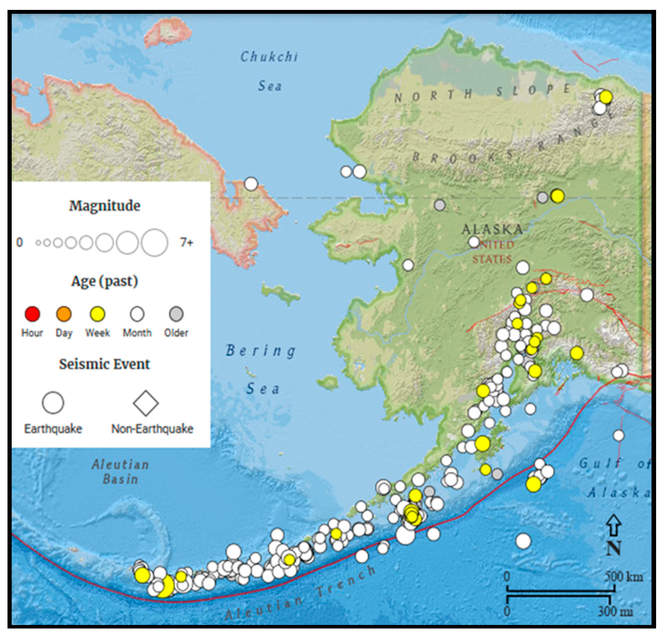
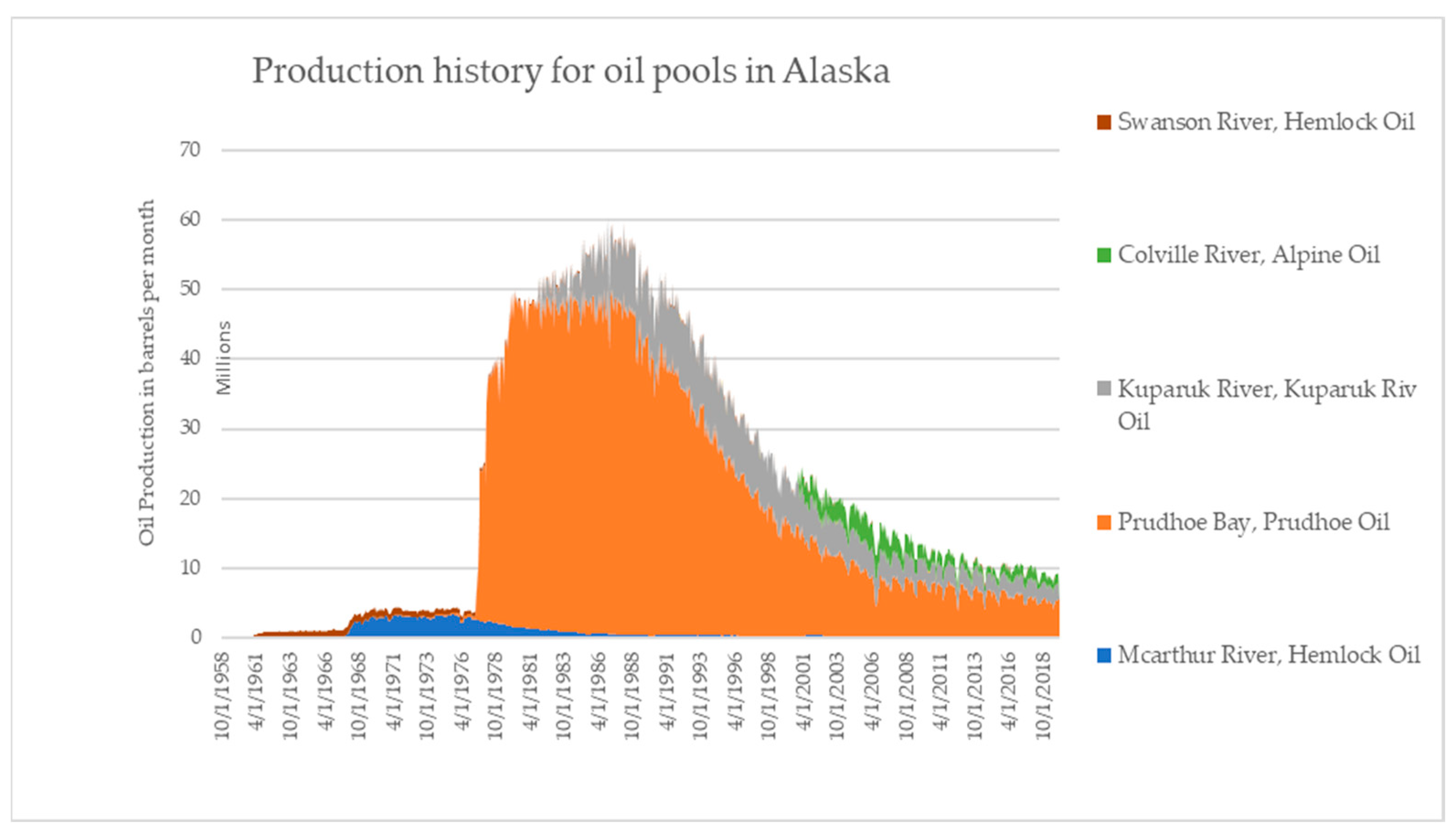
Table 1.
Lithology, Rock and Fluid Properties of Alaskan Oil Pools.
| Reservoir Formation Properties | Oil Properties | |||||||
|---|---|---|---|---|---|---|---|---|
| Oil Pool/Field | H (ft.) | Formation Lithology | ∅ | k (mD) | Swi | μo cp | °API | |
| Badami Pool | 10,500 | This pool consists mainly of separate turbitide sandstone reservoirs from the Tertiary-aged Canning Formation. The sandstone reservoir was deposited within mud-dominated submarine fan systems [53]. | 18.0% | 1–400 | 1.5%–9.6% | 30.5 | ||
| Colville River | Alpine | 7000 | The reservoir is found in the Jurassic-aged Kingak formation within the Colville Delta area [54]. It consists of shallow marine, very fine to medium-grained, quartz-rich sandstone deposits. The reservoir is underlain by silty shale assigned to the Jurassic Miluveach formation [55]. | 15%–23% | 1–160 | 12%–30% | 0.54 | 40 |
| Fiord | 6850 | 11.5%–24% | 5–1000 | 20%–60% | 0.97 | 29 | ||
| Nanuq | 6150 | 17.0% | 2.5 | 32% | 0.5 | 40 | ||
| Qannik | 4000 | 21.0% | 13 | 35% | 2 | 29 | ||
| Endicott | Eider | 9700 | The upper confinement is by the Kayak Shale-Itkilariak formation and in the lower portion by a cretaceous unconformity [56]. Lithostratographic zones 1 comprises shale, coal, and siltstone. Zone 2- medium-grained sandstone. Zone 3- fine-to medium-grained sandstone in stacked point-bar channels [57]. | 21.0% | 134 | 35.0% | 1.56 | 25 |
| Endicott Oil | 10,000 | 21.0% | 1500 | 9.0% | 1.09 | 23.5 | ||
| Ivishak Oil | 10,000 | 21.6% | 600 | 34.0% | 1.56 | 22 | ||
| Granite Pt. | Hemlock | 10,500 | The productive sandstone and conglomerate layers within the pool are found in the lower Tyonek. These layers were deposited in braided streams during the Oligocene to Miocene [58,59]. | 6.6% | 0.5 | 55.0% | 0.53 | 41 |
| Middle Kenai Oil Pool | 8780 | 14.0% | 10 | 39.9% | 0.31 | 41 | ||
| Hansen | 6800 | 12.0% | 17 | 47.0% | 3.5 | 24 | ||
| Kuparuk River | Kuparuk Riv Oil | 6200 | The Kuparuk River Field is the second largest in Alaska, after Prudhoe Bay, located on the Arctic Slope approximately 30 miles west of Prudhoe Bay. The oil field is a sequence of clastic sediments deposited on a shallow marine shelf during the Early Cretaceous time. The Formation is divided into the Lower Member (units A and B) and the Upper Member (units C and D). Units A and C are the leading oil-bearing intervals [60,61]. | 20.5% | 150 | 35.0% | 2.2 | 23 |
| Meltwater Oil | 5400 | 20.0% | 10 | 40.0% | 0.75 | 36 | ||
| Tabasco Oil | 6107 | 22.0% | 5500 | 21.0% | 251 | 16.5 | ||
| Tarn Oil | 6747 | 20.0% | 10 | 40.0% | 0.55 | 37 | ||
| Torok Oil | 5000 | 21.5% | 46.75 | 57.5% | 2.5 | 26.5 | ||
| West Sak Oil | 10,290 | 30.0% | 1007.5 | 30.0% | 42 | 19 | ||
| McArthur River | Hemlock Oil | 10,227 | This field is located offshore Cook Inlet, approximately 64 air miles southwest of Anchorage and 24 air miles northwest of Kenai. The Formation is mainly made of conglomerate sandstone. Three oil-producing formations are located in the Tertiary and one in the Mesozoic. [55,62]. | 10.5% | 53 | 35.0% | 1.19 | 33.1 |
| Midkenai G Oil | 10,227 | 18.1% | 65 | 35.0% | 1.09 | 34 | ||
| Undefined Oil | 10,227 | 4.9% | 6.3 | 34.0% | 1.13 | 33 | ||
| W Foreland Oil | 9650 | 15.7% | 102 | 35.0% | 1.497 | 30.3 | ||
| Milne Point | Kuparuk River Oil | 7000 | The reservoir is divided into four informal units (A, B, C, and D in ascending order). Unit A is composed mainly of fine-grained sandstone, Unit B- interlaminated siltstone, and sandstone. Unit C- medium-grained sandstone, with the overlying Unit D consisting of shale [63,64]. | 21.0% | 40 | 25.0% | 3.2 | 23 |
| Sag River Oil | 8750 | 17.0% | 2 | 40.0% | 0.3 | 38 | ||
| Schrader Blff Oil | 4000 | 29.0% | 1500 | 35.0% | 80 | 14 | ||
| Ugnu Undefined Oil | 3500 | 33.0% | 2500 | 20.0% | 1753 | 13.1 | ||
| Oooguruk | Nuiqsut | 6350 | The Oooguruk field consists of Neocomian, transgressive sediments deposited within a marine shelf and shoreface environment, overlaying the Lower Cretaceous Unconformity. It mainly comprises bioturbated sandstones, siltstones, and mudstones [65,66]. | (2–20)% | 3.1 | 30.0% | 4.5 | 19 |
| Kuparuk | 6050 | (13–32)% | 50 | 30.0% | 2 | 23 | ||
| Torok | 500 | 19.0% | 4 | 52.0% | 3 | 24 | ||
| Prudhoe Bay | North Star Oil | 11,100 | The Prudhoe Bay field encompasses the Sag River, Shublik, and Ivishak formations. Sag River consists of a lower sandstone member and an upper shale member; the Shublik Formation consists of organic-and phosphate-rich sandstone, muddy sandstone, mudstone, silty limestone, and limestone. The principal oil-bearing formation is the Permo-Triassic Ivishak Formation [67]. It consists of sand and conglomerate and lies within the Sadlerochit group. The formation base is made up of clay-stone and shale, which grade upward into interbedded fine-grained sandstone. Overgrowths of silica cement represent the most crucial diagenetic factor limiting porosity across the field [68]. | 15.0% | 366 | 54.0% | 0.14 | |
| Kuparuk | 9000 | 20.1% | 220 | 29.0% | 0.012 | |||
| Aurora Oil | 6700 | 18.0% | 44 | 45.0% | 0.72 | 29.1 | ||
| Borealis Oil | 6600 | 18.0% | 22 | 44.0% | 2.97 | 24.1 | ||
| Lisburne Oil | 8900 | 10.0% | 1 | 30.0% | 0.9 | 27 | ||
| Midnight Sun Oil | 8050 | 21.0% | 540 | 18.0% | 1.68 | 27 | ||
| Prudhoe Bay Oil | 9245 | 20.0% | 265 | 40.0% | 0.425 | 32.5 | ||
| Niakuk Oil | 9200 | 20.0% | 500 | 28.0% | 0.94 | 25 | ||
| Polaris Oil | 5000 | 26.4% | 78 | 54.0% | 8 | 18.2 | ||
| Prudhoe Oil | 8800 | 22.0% | 265 | 30.0% | 0.81 | 28 | ||
| Pt Mcintyre Oil | 8800 | 22.0% | 200 | 15.0% | 0.9 | 27 | ||
| Put River Oil | 8100 | 19.0% | 173 | 46.0% | 1.84 | 26.9 | ||
| Raven Oil | 9850 | 20.0% | 265 | 30.0% | 0.4 | 32 | ||
| Schrader Bluf Oil | 4400 | 27.6% | 220 | 46.5% | 11.2 | 18.7 | ||
| W Beach Oil | 8800 | 11.0% | 37 | 58.0% | 1.08 | 25.7 | ||
| Trading Bay | G-Ne_Hemlk-Ne Oil | 9500 | The Trading Bay reservoir is loaded Offshore Cook Inlet in a slightly asymmetrical anticline. The lithology primarily consists of sand conglomerate. The main phase of structural development occurred in the Middle to Late Miocene as theCook Inlet Basin underwent a period of increased transpression [69,70]. | 14.0% | 6.4 | 37.0% | 0.87 | 36 |
| Hemlock Oil | 4400 | 15.0% | 169 | 43.0% | 0.91 | 34.5 | ||
| Mid Kenai B Oil | 4400 | 24.0% | 85 | 36.0% | 8.1 | 22.7 | ||
| Mid Kenai C Oil | 4400 | 20.0% | 69 | 34.0% | 4.1 | 25.7 | ||
| Mid Kenai D Oil | 4400 | 16.0% | 41 | 35.0% | 1.23 | 31.5 | ||
| Mid Kenai E Oil | 4400 | 17.0% | 60 | 38.0% | 0.753 | 29.3 | ||
| Undefined Oil | 4400 | 21.0% | 85 | 40.0% | 8.1 | 23 | ||
Table 2.
An Overview of EOR Techniques Studied and Employed in Alaska.
| EOR Technique | Status | Reference |
|---|---|---|
| Polymer flooding | Field experiment | [12] |
| [13,73] | ||
| Solvent Based EOR | Field experiment | [74,75] |
| [76] | ||
| Low Salinity waterflood | Laboratory studies | [35] |
| [34] | ||
| [77] | ||
| Miscible flooding and viscosity reducing WAG process | Field experiment | [6,75,78,79] |
| Immiscible Water-Alternating-Gas injection | Simulation studies | [80] |
| Alkali-Surfactant-Polymer (ASP) flooding | Simulation Studies | [21,81] |
| CO2 stimulation (Huff and Puff) | Simulation studies | [1] |
| Microbial Enhanced Oil Recovery | Laboratory studies | [82,83,84] |
| CO2 flooding in methane gas hydrates | Field experiment | [85,86] |
Table 3.
Screening criteria for application of CO2-miscible flooding, adapted from [28]. Varying depths, as mentioned for OTA (1978) [100] and Taber et al. (1997a) [90], correspond to API gravity.
| Reservoir Parameter | Reported by | ||||||||
|---|---|---|---|---|---|---|---|---|---|
| Reservoir Parameter | Geffen (1973) [101] | Lewin et al. (1976) [102] | NPC (1976) [103] | McRee (1977) [104] | Iyoho (1978) [105] | OTA (1978) [100] | Carcoana (1982) [106] | Taber & Martin (1982) s | Taber et al. (1997a) [90] |
| Depth (ft.) | >3000 | >2300 | > 2000 | >2500 | i) >7200 ii) >5500 iii) >2500 | <9800 | >2000 | i) >4000 ii) >3300 iii) >2800 iv) >2500 | |
| Temperature (oF) | NC* | <250 | <195 | NC* | |||||
| Original Pressure (psia) | >1100 | >1500 | >1200 | ||||||
| Permeability (mD) | NC * | >5 | >10 | >1 | NC * | ||||
| Oil Gravity (oAPI) | >30 | >30 | >27 | >35 | 30–45 | i) <27 ii) 27–30 iii) >30 | >40 | >26 | i) 22–27.9 ii) 28–31.9 iii) 32–39.9 iv) >40 |
| Viscosity (cP) | <3 | <12 | <10 | <5 | <10 | <12 | <2 | <15 | <10 |
| SOR | >0.25 | >0.25 | >0.25 | >0.25 | >0.30 | >0.30 | >0.2 | ||
* NC represents non-critical reservoir parameter in the screening.
Table 4.
Estimates of CO2-crude Oil Minimum Miscibility Pressure (MMP) Adapted from [103].
Table 4.
Estimates of CO2-crude Oil Minimum Miscibility Pressure (MMP) Adapted from [103].
| Oil Gravity (o API) | MMP (psi) | Temperature (oF) | Minimum Reservoir Pressure Requirement (psi) |
|---|---|---|---|
| <27 | 4000 | 120 | 0 |
| 27–30 | 3000 | 120–150 | 200 |
| >30 | 1200 | 150–200 | 350 |
| 200–250 | 500 |
Table 5.
CO2 sequestration Ranking for Alaskan Oil Pools When Pressurized to Original Reservoir Pressures, adapted from [27,55].
| Rank | Field | Reservoir Temperature oF | Reservoir Pressure, Psi | Potential Mass of CO2 Storage (Mt) |
|---|---|---|---|---|
| 1 | Prudhoe Bay | 200 | 4335 | 3.99 × 10⁹ |
| 2 | Kuparuk | 160 | 3135 | 2.09 × 10⁹ |
| 3 | Lisburne | 183 | 4490 | 4.60 × 10⁸ |
| 4 | Endicott-Keiktuk | 218 | 4870 | 3.56 × 10⁸ |
| 5 | West Sak | 75 | 1600 | 3.04 × 10⁸ |
| 6 | Schrader Bluff | 80 | 1800 | 2.05 × 10⁸ |
| 7 | Orion | 87 | 1950 | 1.06 × 10⁸ |
| 8 | Point McIntyre | 180 | 4377 | 1.46 × 10⁸ |
| 9 | Milne Point | 170 | 3700 | 1.23 × 10⁸ |
| 10 | Colville River | 160 | 3215 | 1.07 × 10⁸ |
| 11 | Polaris | 100 | 2250 | 6.83 × 10⁷ |
| 12 | Niakuk | 187 | 4446 | 6.47 × 10⁷ |
| 13 | NorthStar | 254 | 5305 | 4.96 × 10⁷ |
| 14 | Meltwater | 140 | 2370 | 4.67 × 10⁷ |
| 15 | Borealis | 158 | 3439 | 4.05 × 10⁷ |
| 16 | Aurora | 150 | 3433 | 3.94 × 10⁷ |
| 17 | Midnight Sun | 160 | 4045 | 3.28 × 10⁷ |
| 18 | Tarn | 142 | 2365 | 3.20 × 10⁷ |
| 19 | Endicott-Eider | 206 | 4635 | 1.08 × 10⁷ |
| 20 | West Beach | 175 | 4257 | 6.76 × 10⁶ |
| 21 | Badami | 180 | 6300 | 4.86 × 10⁵ |
Table 6.
Summary of CO2-flooding Screening Criteria Used in This Study Based on Six Reservoir Parameters from [10].
Table 6.
Summary of CO2-flooding Screening Criteria Used in This Study Based on Six Reservoir Parameters from [10].
| Reservoir Parameter | Shaw & Bachu, 2002 [28] |
|---|---|
| Depth (ft.) | Not critical. Geothermal conditions and hydrodynamic regimes may mask the influence of depth |
| Temperature (oF) | 195–250 |
| Current Pressure (psia) | 200 psi > MMP, greater than Pc of CO2, and (P/MMP) > 0.95 |
| Permeability (mD) | not critical |
| Oil Gravity (oAPI) | >27 but <48 |
| Viscosity (cP) | not critical |
| SOR | >0.25 |
Table 7.
CO2 flooding Screening for Alaskan Oil Pools, Data Gathered from Alaska Oil and Gas Conservation Commission (AOGCC) [55].
Table 7.
CO2 flooding Screening for Alaskan Oil Pools, Data Gathered from Alaska Oil and Gas Conservation Commission (AOGCC) [55].
| Oil Pool | MD (ft.) | T (°F) | P (psi) | k (mD) | API (°API) | μ (cP) | MMP | P/MMP | Suitability for CO2 Flooding |
|---|---|---|---|---|---|---|---|---|---|
| Badami Pool | 10,500 | 180 | 6300 | 1–400 | 30.5 | 3000 | 2.10 | possible | |
| Beaver Creek, Beaver Creek Oil | 15,717 | 0.5–75 | 34.5 | 1200 | 0.00 | not recommended | |||
| Alpine Colville River | 7000 | 160 | 3537 | 1–1000 | 40 | 0.54 | 1200 | 2.95 | possible |
| Fiord Colville River | 6850 | 165 | 3150 | 5–1000 | 29 | 0.97 | 3000 | 1.05 | possible |
| Nanuq Colville River | 6150 | 135 | 2600 | 2.5 | 40 | 0.5 | 1200 | 2.17 | possible |
| Qannik Colville River | 4000 | 89 | 1850 | 13 | 29 | 2 | 3000 | 0.62 | not recommended |
| Eider Endicott | 9700 | 206 | 1380 | 134 | 25 | 1.56 | 4000 | 0.35 | not recommended |
| Endicott Oil | 10,000 | 218 | 4397 | 1500 | 23.5 | 1.09 | 4000 | 1.10 | not recommended |
| Endicott Ivishak Oil Pool | 10,000 | 212 | 3699 | 600 | 22 | 1.56 | 4000 | 0.92 | not recommended |
| Hemlock Undef. Grante Pt. | 10,500 | 185 | 5500 | 0.5 | 41 | 0.53 | 1200 | 4.58 | possible |
| Middle Kenai Oil Pool | 8780 | 174 | 2620 | 10 | 41 | 0.31 | 1200 | 2.18 | possible |
| Hansen | 6800 | 135 | 2582 | 17 | 24 | 3.5 | 4000 | 0.65 | not recommended |
| Kuparuk River, Kuparuk River Oil | 6200 | 160 | 3106 | 150 | 23 | 2.2 | 4000 | 0.78 | not recommended |
| Kuparuk River, Meltwater Oil | 5400 | 140 | 2300 | 10 | 36 | 0.75 | 1200 | 1.92 | possible |
| Kuparuk River, Tabasco Oil | 6107 | 71 | 1250 | 5500 | 16.5 | 251 | 4000 | 0.31 | not recommended |
| Kuparuk River, Tarn Oil | 6747 | 142 | 2430 | 10 | 37 | 0.55 | 1200 | 2.03 | possible |
| Kuparuk River, Torok Oil | 5000 | 140 | 1995 | 46.75 | 26.5 | 2.5 | 4000 | 0.50 | not recommended |
| Kuparuk River, West Sak Oil | 10,290 | 75 | 1600 | 1007.5 | 19 | 42 | 4000 | 0.40 | not recommended |
| McArthur River, Hemlock Oil | 10,227 | 180 | 3600 | 53 | 33.1 | 1.19 | 1200 | 3.00 | possible |
| McArthur River, Midkenai G Oil | 10,227 | 174 | 2525 | 65 | 34 | 1.09 | 1200 | 2.10 | possible |
| McArthur River, Undefined Oil | 10,227 | 195 | 7000 | 6.3 | 33 | 1.13 | 1200 | 5.83 | possible |
| McArthur River, W Foreland Oil | 9650 | 183 | 4000 | 102 | 30.3 | 1.497 | 3000 | 1.33 | possible |
| Middle Ground Shoal, Mgs Oil | 8000 | 155 | 2900 | 10 | 36.6 | 0.71 | 1200 | 2.42 | possible |
| Milne Point, Kuparuk River Oil | 7000 | 175 | 3268 | 40 | 23 | 3.2 | 4000 | 0.82 | not recommended |
| Milne Point, Sag River Oil | 8750 | 226 | 2439 | 2 | 38 | 0.3 | 1200 | 2.03 | possible |
| Milne Point, Schrader Bluff Oil | 4000 | 80 | 1539 | 1500 | 14 | 80 | 4000 | 0.38 | not recommended |
| Milne Point, Ugnu Undefine Oil | 3500 | 70 | 1540 | 2500 | 13.1 | 1753 | 4000 | 0.39 | not recommended |
| Orion | 4515 | 94 | 1800 | 333.77 | 17 | 4000 | 0.75 | not recommended | |
| Oooguruk Nuiqsut | 6350 | 160 | 2995 | 3.1 | 19 | 4.5 | 4000 | 0.63 | not recommended |
| Oooguruk Kuparuk | 6050 | 160 | 2500 | 50 | 23 | 2 | 4000 | 0.56 | not recommended |
| Oooguruk Torok | 500 | 135 | 2250 | 4 | 24 | 3 | 4000 | 0.56 | not recommended |
| North Star, North Star Oil | 11,100 | 254 | 5305 | 366 | 0.14 | 4000 | 1.33 | not recommended | |
| Northstar, Kuparuk | 9000 | 197 | 2865 | 220 | 0.012 | 4000 | 0.72 | not recommended | |
| Prudhoe Bay, Aurora Oil | 6700 | 150 | 3016 | 44 | 29.1 | 0.72 | 3000 | 1.01 | possible |
| Prudhoe Bay, Borealis Oil | 6600 | 158 | 3075 | 22 | 24.1 | 2.97 | 4000 | 0.77 | not recommended |
| Prudhoe Bay, Lisburne Oil | 8900 | 183 | 2990 | 1 | 27 | 0.9 | 3000 | 1.00 | not recommended |
| Prudhoe Bay, Midnight Sun Oil | 8050 | 160 | 3439 | 540 | 27 | 1.68 | 3000 | 1.15 | not recommended |
| Prudhoe Bay, N Prudhoe Bay Oil | 9245 | 206 | 3610 | 265 | 32.5 | 0.425 | 1200 | 3.01 | possible |
| Prudhoe Bay, Niakuk Oil | 9200 | 187 | 4094 | 500 | 25 | 0.94 | 4000 | 1.02 | not recommended |
| Prudhoe Bay, Polaris Oil | 5000 | 98 | 1925 | 78 | 18.2 | 8 | 4000 | 0.48 | not recommended |
| Prudhoe Bay, Prudhoe Oil | 8800 | 200 | 3360 | 265 | 28 | 0.81 | 3000 | 1.12 | possible |
| Prudhoe Bay, Pt McIntyre Oil | 8800 | 180 | 3867 | 200 | 27 | 0.9 | 3000 | 1.29 | not recommended |
| Prudhoe Bay, Put River Oil | 8100 | 182 | 4297 | 173 | 26.9 | 1.84 | 4000 | 1.07 | not recommended |
| Prudhoe Bay, Raven Oil | 9850 | 207 | 4210 | 265 | 32 | 0.4 | 1200 | 3.51 | possible |
| Prudhoe Bay, Schrader Bluff Oil | 4400 | 87 | 1763 | 220 | 18.7 | 11.2 | 4000 | 0.44 | not recommended |
| Prudhoe Bay, W Beach Oil | 8800 | 175 | 3609 | 37 | 25.7 | 1.08 | 4000 | 0.90 | not recommended |
| Pt Thomson, Thomson Oil | 12,500 | 195 | 23 | 4000 | 0.00 | not recommended | |||
| Trading Bay, G-Ne/Hemlk-Ne Oil | 9500 | 165 | 2100 | 6.4 | 36 | 0.87 | 1200 | 1.75 | possible |
| Trading Bay, Hemlock Oil | 4400 | 177 | 1849 | 169 | 34.5 | 0.91 | 1200 | 1.54 | possible |
| Trading Bay, Mid Kenai B Oil | 4400 | 104 | 985 | 85 | 22.7 | 8.1 | 4000 | 0.25 | not recommended |
| Trading Bay, Mid Kenai C Oil | 4400 | 111 | 1900 | 69 | 25.7 | 4.1 | 4000 | 0.48 | not recommended |
| Trading Bay, Mid Kenai D Oil | 4400 | 135 | 1900 | 41 | 31.5 | 1.23 | 1200 | 1.58 | possible |
| Trading Bay, Mid Kenai E Oil | 4400 | 143 | 1644 | 60 | 29.3 | 0.753 | 3000 | 0.55 | not recommended |
| Trading Bay, Undefined Oil | 4400 | 90 | 1310 | 85 | 23 | 8.1 | 4000 | 0.33 | not recommended |
Publisher’s Note: MDPI stays neutral with regard to jurisdictional claims in published maps and institutional affiliations. |
© 2021 by the authors. Licensee MDPI, Basel, Switzerland. This article is an open access article distributed under the terms and conditions of the Creative Commons Attribution (CC BY) license (http://creativecommons.org/licenses/by/4.0/).
Share and Cite
MDPI and ACS Style
Dogah, B.; Atashbari, V.; Ahmadi, M.; Sheets, B. Enhanced Oil Recovery Using CO2 in Alaska. Geosciences 2021, 11, 98. https://0-doi-org.brum.beds.ac.uk/10.3390/geosciences11020098
AMA Style
Dogah B, Atashbari V, Ahmadi M, Sheets B. Enhanced Oil Recovery Using CO2 in Alaska. Geosciences. 2021; 11(2):98. https://0-doi-org.brum.beds.ac.uk/10.3390/geosciences11020098
Chicago/Turabian StyleDogah, Banabas, Vahid Atashbari, Mohabbat Ahmadi, and Brent Sheets. 2021. "Enhanced Oil Recovery Using CO2 in Alaska" Geosciences 11, no. 2: 98. https://0-doi-org.brum.beds.ac.uk/10.3390/geosciences11020098
Note that from the first issue of 2016, this journal uses article numbers instead of page numbers. See further details here.