
Effect of Geometric Parameters and Construction Sequence on Ground Settlement of Offset Arrangement Twin Tunnels


Department of Civil and Urban Engineering, Tandon School of Engineering, New York University, Brooklyn, NY 11201, USA
*
Author to whom correspondence should be addressed.
Geosciences 2022, 12(1), 41; https://0-doi-org.brum.beds.ac.uk/10.3390/geosciences12010041
Submission received: 2 December 2021
/
Revised: 7 January 2022
/
Accepted: 10 January 2022
/
Published: 14 January 2022
(This article belongs to the Collection New Advances in Geotechnical Engineering)
Abstract
:A parametric study that examines the ground surface settlement due to the excavation of shallow offset arrangement twin tunnels is presented. Offset arrangement tunnels are those that run parallel to each other, but at different elevations. The study focuses on the influence of both the construction sequence and various geometric parameters on the induced soil settlement. A series of three-dimensional finite element analyses was carried out to investigate the settlement behavior and interactions between offset arrangement twin tunnels excavated in clay using a simplified mechanized excavation method. Analyses were carried out for three cover-to-diameter (C/D) ratios, three possible construction sequences, five angular relative positions, and five angular spacings. In addition, settlement data were also investigated by varying horizontal and vertical spacings while keeping the angular spacing constant. The total settlement of the excavated twin tunnels and the settlement induced solely by the new second tunnel are both presented, and special attention was paid to identifying the dominant geometric parameters. The observed data trends from this study are generally consistent with the limited data available in the literature. This study confirmed a few perceived behaviors. First, angular relative position better describes the settlement behavior in comparison to angular spacing. Second, the effect of the vertical distance is noticeably more significant than that of the horizontal distance between the two tunnels. Third, excavation of the lower tunnel at first induces higher total ground settlement than when the upper tunnel is excavated first or when both tunnels are excavated concurrently. Fourth, settlement due to the construction of the newer tunnel decreases with the increase in the cover depth. In addition, two design charts have been proposed to calculate the settlement induced from a new second tunnel excavation and the eccentricity of the maximum total settlement relative to the center of the new tunnel.
1. Introduction
The demand for reliable and environmentally sustainable infrastructure in major urban centers increasingly requires the construction of twin tunnels, where two or more new tunnels are often constructed near to each other. The same demands often result in building new tunnels near or parallel to existing tunnels. Shallow twin tunnel construction, particularly in soft ground, has the potential to cause deleterious ground settlements that may damage existing buildings and sub-surface infrastructure located within the influence zone. Choi and Lee [1] investigated the influence of the size of an existing tunnel and the distance between tunnel centers, among other factors, on the structural behavior of the existing and new tunnels by quantifying the displacement and crack propagation during the excavation of a new tunnel constructed near an existing tunnel. As expected, they found that the displacements decreased and stabilized as the distance between the tunnel centers increased, depending on the size of the existing tunnel.
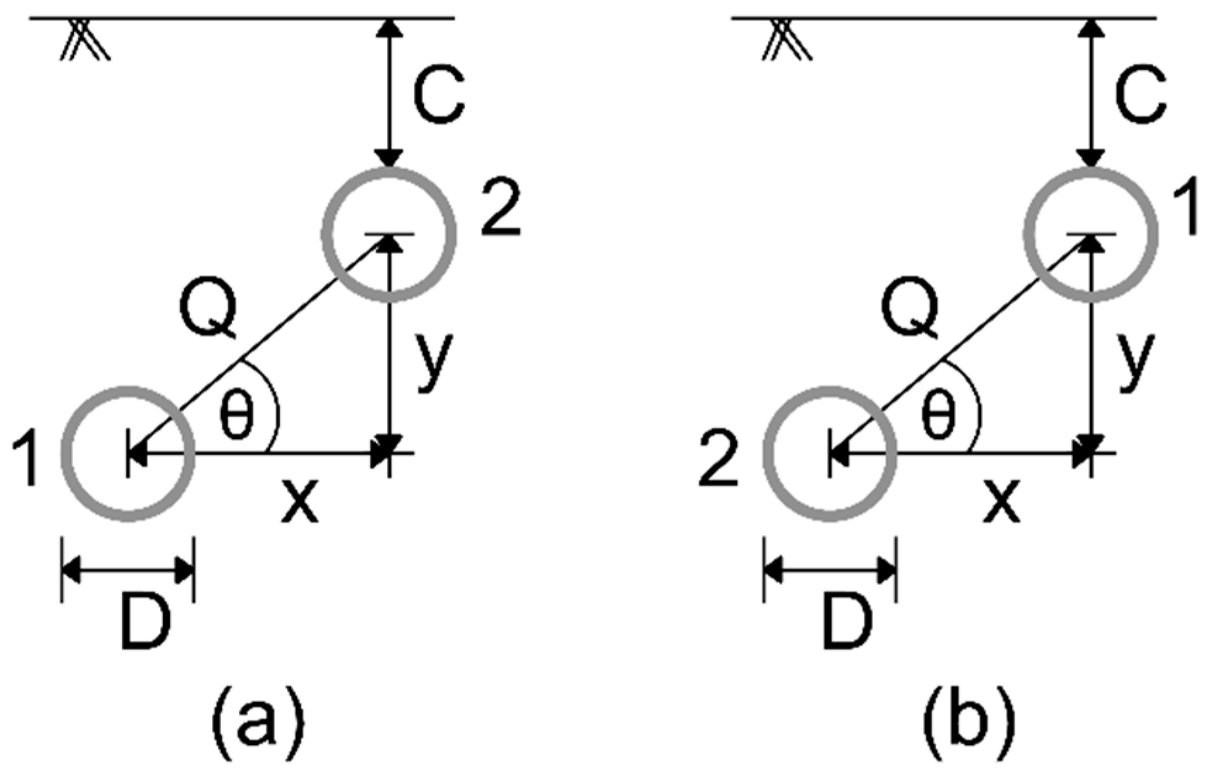
Twin tunnels are constructed in many configurations that differ in terms of geometric position. Offset arrangement twin tunnels run parallel to each other, but at differing elevations while maintaining their horizontal distance as shown in Figure 1. Due to their offset positioning in both horizontal and vertical directions, offset arrangement twin tunnels offer flexibility compared to other twin tunnel geometries in dense developed areas where there is other sub-surface infrastructure that must be bypassed. For any twin tunnel excavation, the main challenges include evaluation and control of ground settlements, stability of the excavation front, as well as deformations, loads, and stresses in the lining. Ground movement is a complex three-dimensional problem that is not only influenced by the tunnel geometry and soil conditions, but also by construction details. For offset arrangement twin tunnels, the excavations are undertaken at different elevations; thus, the interactions can have unanticipated influences on surface and subsurface settlements in addition to the stress distributions and deformations of the tunnel lining. Interaction between two tunnels and induced ground settlements for offset arrangement excavation are not well understood, considering that not many investigations have been done, be it field observations, laboratory experiments, or numerical analyses.
Addenbrooke [2] reported that offset arrangement tunnels demonstrate characteristics of both side-by-side and piggyback tunnels. However, it is important to distinguish offset arrangement twin tunnels from both side-by-side (horizontally aligned) and piggyback (vertically aligned) twin tunnels as closely aligned side-by-side and piggyback tunnels often benefit from the reinforcing effect of the first tunnel [3]. Fang et al. [4] found that newly constructed offset arrangement tunnels in a greenfield site demonstrated twice as much settlement than a set of newly constructed piggyback tunnels. Similarly, Standing et al. [5] reported larger volume loss for the new offset arrangement upper tunnel together with a bigger trough width and maximum settlement offset towards the first tunnel excavated at St. James Park, London. Conversely, Nyren [6] reported no offset in the position of the maximum settlement above the second tunnel driven, at the same location.
Available studies summarized by Islam and Iskander [3] shed some light on the effect of angular spacing (i.e., the diagonal distance between two tunnels) and the construction sequence on induced ground settlements. However, the findings remain discrete and unclear due to (i) lack of data for many geometric and field conditions and (ii) the compared data are gathered from studies employing different field conditions, tunnelling processes, geometric dimensions, and study methodologies, making it difficult to properly compare the results and infer the governing phenomena. For example, the effect of cover depth on the induced settlement and its behavior is not clear, and it is also not clear whether variation in horizontal distance impacts ground settlement generation more or the variation in the vertical distance. Similarly, available studies do not provide conclusive information related to concurrent excavation of offset arrangement tunnels and how it differs from staggered excavation. Chehade and Shahrour [7] presented numerical results for two offset geometries varying the distance in the horizontal direction while keeping the distance in the vertical direction and cover depth constant. In their study, they observed that the construction of the lower tunnel at first leads to higher soil settlement than that induced when the upper tunnel is first excavated. However, concurrent excavation of both tunnels was not studied. Thus, there is a compelling need to investigate the three-dimensional (3D) effects of the construction sequence to understand the interactive behavior between offset arrangement tunnels during construction.
Interactions between closely spaced tunnels were studied in the past using a variety of approaches including physical model tests, field observations, empirical/analytical methods, and finite element modelling. Among these, finite element modelling is more convenient for conducting parametric studies. In this work, a series of systematic 3D coupled finite element analyses (FEA) were carried out to investigate the interactions between twin tunnels, which are not aligned in any direction and constructed in clay using a tunnel boring machine (TBM). The scope of this study involves looking at the effects of various geometric parameters as well as the effect of three possible construction sequences on observed ground settlements. The numerical TBM model employed is capable of taking into consideration a large number of processes that take place during tunnel excavation. Attention was paid to the identification of various factors which can affect induced settlements and how these factors play a role in defining the magnitude and position of the maximum settlement. The influence of the tunnel distance in both horizontal and vertical direction, as well as angular distance, cover depth, and excavation sequence, were also explored. The objective of this work is to aid in optimization of both the relative position of twin tunnels and the construction sequence to yield comparatively low settlement while excavating offset arrangement twin tunnels.
2. Three Dimensional Numerical Simulation
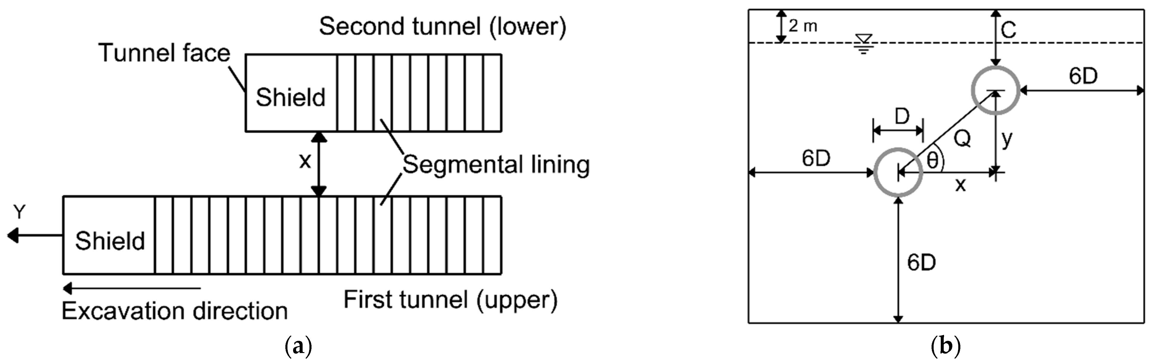
Three-dimensional numerical investigations were conducted using the finite element program MIDAS GTS NX 2019 (v2.1) [8]. A tunnel excavation model is developed using the software, suitable for evaluation of the effects of excavation sequences and geometric parameters on the ground settlements induced by the excavation. The software allows step-by-step analysis of excavation, application of loading, and other factors that affect the process of tunneling. The program supports various soil characteristics, loading and boundary conditions, and analytical methodologies to simulate real tunnelling operations. The plan view of the offset arrangement twin tunnels excavation and typical cross section of the 3D model of twin tunnels excavation employed is illustrated in Figure 2. Twenty-seven numerical models encompassing nine geometries and three construction sequences were carried out as shown in Table 1.
2.1. Constitutive Model Parameters
Geotechnical parameters of the clay used in this numerical parametric study were assumed as representative of the properties of the silty clay layer, which was encountered during excavation of the north route transit tunnel of Shanghai Railway transportation line 11 and reported by Zhang and Huang [9]. The behavior of clay used in this study is described using a constitutive model similar to that used by Addenbrooke and Potts [10], Galli et al. [11] and Ieronymaki et al. [12], among others, where the Mohr–Coulomb model is employed to simulate clay behavior. The Mohr–Coulomb failure criterion is not fully able to reproduce certain aspects of clay behavior particularly during unloading, including tunnel excavation. Nevertheless, it was chosen in this study due to its simplicity and the parametric nature of the work where various configurations of twin tunnel geometric parameters as well as tunnel excavation depth were compared to each other.
To accommodate the increase in the strength of the clay with depth the soil was represented using a combination of cohesion and an angle of internal friction. An angle of friction of 15° was selected, which effectively corresponds to a c/σ(Z) ratio of 0.27, where c is cohesion, and σ(Z) is the effective vertical overburden stress, both at the location of interest. c/σ(Z) has been found to be useful for describing the increase in strength with depth in thick clay deposits [13,14]. A value of 0.27 is consistent with a normally consolidated clay having a plasticity index (PI) of approximately 40, or a lightly over-consolidated low plasticity clay having a PI of 20. Within the Mohr–Coulomb model, the soil stiffness is considered constant in the elastic zone until the stress state reaches the plastic zone of failure. To accommodate the increase in stiffness with depth Young’s modulus of the soil was increased with depth following Janbu [15] relation presented in Equation (1).
where Es denotes Young’s modulus of the soil, and σ is the mean stress due to the soil self-weight, which is determined using Equation (2).
where Z denotes depth, γ is soil unit weight, Pref is a reference pressure (100 kPa), E0 designates the Young’s modulus when σ = Pref, and Z0 is the thickness of the surface soil layer, which is assumed to have a constant stiffness. K0 is the coefficient of lateral earth pressure at rest, which is calculated from Jaky’s [16] equation as (1 − sin ϕ).
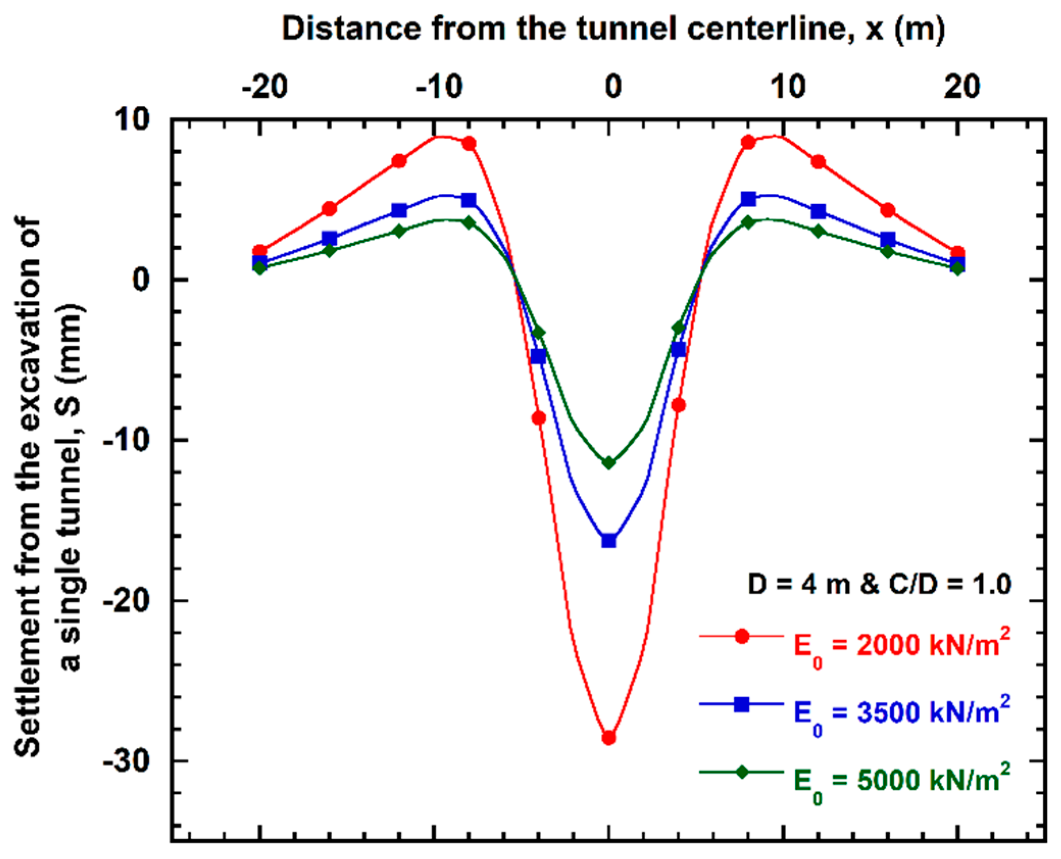
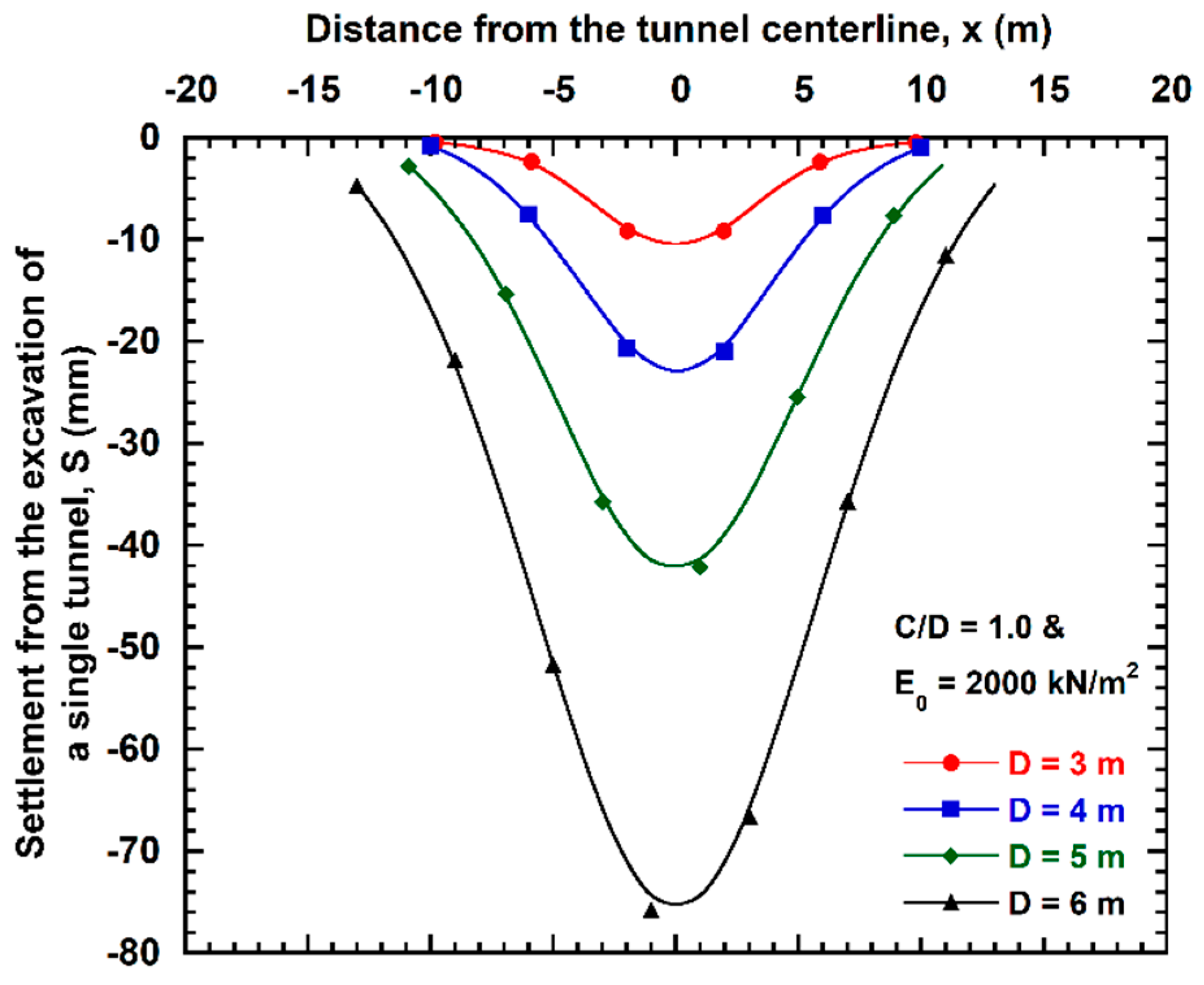
The magnitude of settlement induced from a tunnel excavation in an FEA study largely depends on the modulus of elasticity assumed for the top layer of the soil. Settlement analysis for a single tunnel has been performed for three different moduli of elasticity, and the observed settlements are plotted in Figure 3. It shows that an increase in modulus of elasticity for the top soil layer can noticeably decrease induced settlement. A modulus of elasticity of E0 = 2000 kN/m2 was selected to amplify the observed settlement in the context of a parametric study. The modulus of elasticity was increased with depth at a rate of 1500 kN/m3 per meter. The initial stresses also include a hydrostatic pore water pressure profile from a water table located 2 m below the ground surface, as shown in Figure 2. Soil layers in all analyses are modeled in terms of undrained conditions.
The behavior of the segmental tunnel lining has been assumed to be isotropic elastic and is modelled as a drained material. The thickness of the lining modelled in this study is equal to 0.25 m. The properties of both the soil and the lining used in this study are summarized in Table 2.
2.2. Finite Element Mesh and Initial Ground Conditions
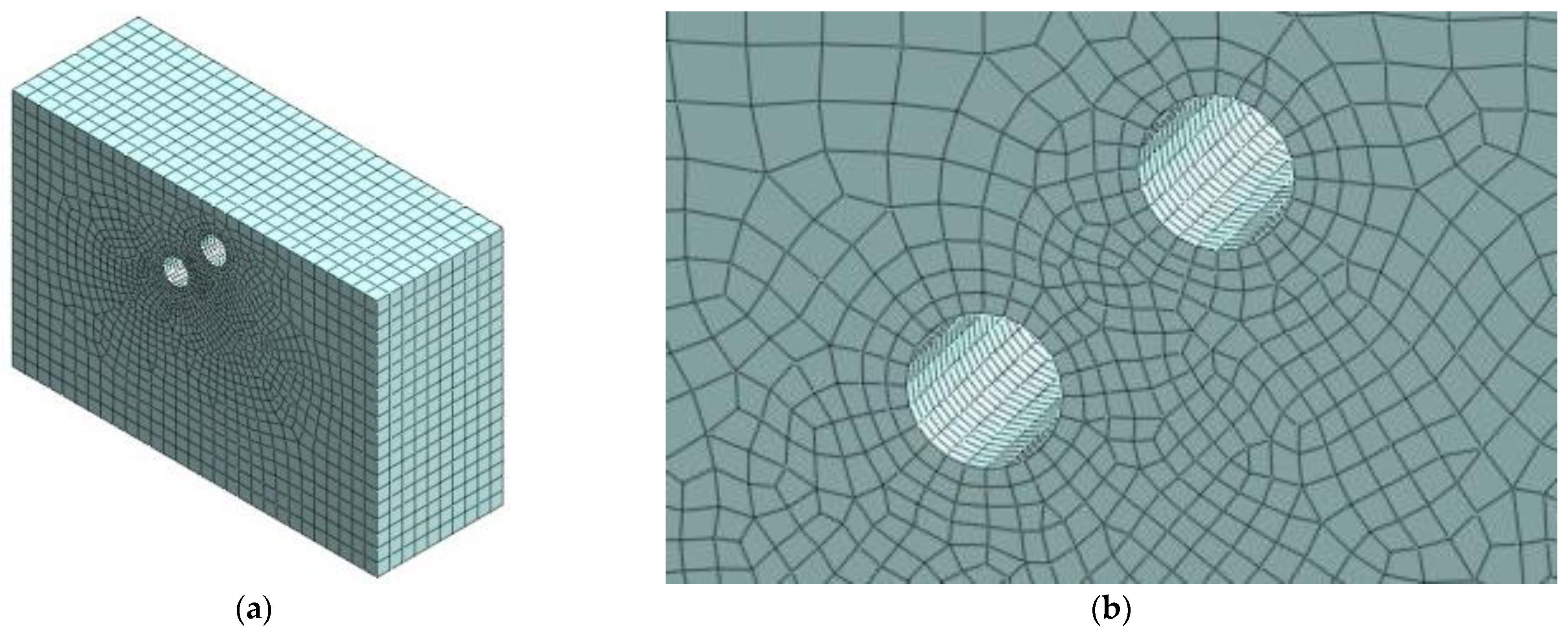
A 3D isometric view of the finite element mesh of the twin offset arrangement tunnels (ID# 1) is presented in Figure 4. In order to minimize boundary effects, the length of the mesh in the lateral (x) direction extends 6.0D from the springlines of both tunnels. The depth of the mesh also extends 6.0D below the lowest tunnel invert to the model boundary, which exceeds five times the excavation depth, as suggested by Li et al. [17]. The distance between the two tunnels in both x and y directions as well as the distance of the upper tunnel crown to the surface are variable due to the parametric nature of the work.
The soil was modeled using a hybrid mesher to increase accuracy while the tunnel lining was modeled using a six-node elastic plate element. While meshing, the tunnel excavation was meshed first followed by meshing of the remaining soil mass. Mesh sizes used in this study are 0.5 m and 2.0 m, respectively, for the excavated tunnels and the soil mass. “Match adjacent faces” command was employed, which effectively reduces the mesh size near the tunnel, to increase the numerical accuracy near the tunnel face.
The tunnel linings were constrained to move with the surrounding soils, and the effect of the installation procedure was ignored. As for the boundary conditions, the displacements were set to zero in the three directions at the bottom of the mesh with no horizontal or vertical movements permitted. Movements in two horizontal directions were restrained, and only vertical movement was allowed on the four side boundaries.
2.3. Tunnel Geometry and Excavation Mechanism
The TBM shield used in the FEA models of this study has been modelled using a simplified geometry and is cylindrical in shape instead of an actual cone-shaped shield. Most of the main operational elements of a mechanized excavation have been simulated in this model, including the face pressure applied on the shield excavation face and the jack thrust. Face pressure has been estimated depending on the horizontal stress induced in the ground in front of the tunnel face following the methodology presented by Anagnostou and Kovari [18], where face pressure has been modelled by applying a pressure distribution to the excavation face. The distribution of the jack thrust has been assumed to be uniform around the perimeter of the tunnel lining segment. The jacking forces adopted in this study are based on the theoretical method proposed by Rijke [19]. The shield external pressure and segment external pressure were applied around the shield excavation face.
Grouting pressure behind the shield tail was also simulated. Grouting pressure has been estimated based on the ground overburden pressure at the crown of excavated tunnels [20]. The grout was simulated using a uniform pressure distribution, which was applied in between the cylindrical surface of the excavated ground and the external surface of the tunnel lining segment. The grout was assumed to harden beyond the length of one lining segment ring (0.25D or 1.0 m in this study) and was simulated by means of an isotropic elastic material having an elastic modulus, Egrout of 1e4 kN/m2 and, Poisson’s ratio, νgrout = 0.22 [20].
To simplify the model and to minimize the computational time the weight of the components of a mechanized tunnelling process were not considered, including the weight of the shield machine and the weight of the back-up train behind the shield machine. This was justified by the parametric nature of the comparison. The effect of this assumption is believed to be minor in the context of a comparative parametric study. The pressure parameters used in this study for analysis ID #3 are summarized in Table 3. The analysis and the parametric study are sensitive to the pressure parameters employed, and thus the simulations are representative of the indicated parameters and are useful for comparison of geometric properties. If tunnels are installed with TBMs employing different operating parameters, the magnitude of geometric inferences outlined herein may not necessarily hold. In particular, variation in pressure parameters during twin tunneling will impact the magnitude of settlement obtained relative to the parametric simulations presented herein.
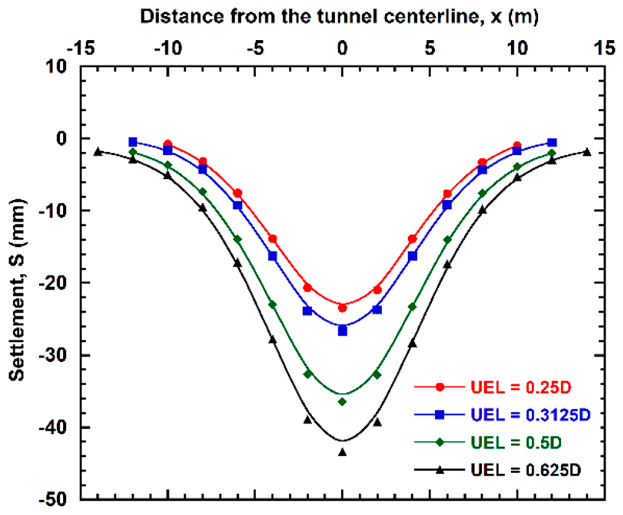
The tunnel construction process is modelled using a step-by-step approach. Each excavation step corresponds to an advancement of the tunnel face of 1.0 m (equivalent to 0.25D), which is followed by installation of a lining ring. The influence of the tunnel length advancement without any support (i.e., lining segment), in other words, unsupported excavation length (UEL), has been evaluated for a single tunnel, and it is evident from Figure 5 that UEL has significant impact on induced ground settlement. The higher the UEL, the higher the induced settlement is. Thus, to minimize the impact resulting from longer UELs, a low UEL of 0.25D has been used throughout this study.
The diameter of the excavated tunnel also has a significant impact on the induced settlement. Settlements induced by a single tunnel for four different diameters are plotted in Figure 6, and it is observed that the larger the tunnel diameter, the larger the settlement. Larger tunnels require much larger models with resulted in longer computational time when doing stage analysis. Therefore, a circular tunnel having a relatively small diameter of 4.0 m has been modelled in this study to reduce computation time and to allow relatively more stages and low UEL in the excavation, which resulted in increased accuracy of a finite element (FE) model.
Three excavation sequences were modelled as follows: (i) excavation of the first tunnel (left and lower) and then excavation of the second tunnel (right and upper), (ii) excavation of the first tunnel (right and upper) and then excavation of the second tunnel (left and lower), and (iii) concurrent excavation of both lower left tunnel and upper right tunnel. For cases (i) and (ii), successive excavation of the new second tunnel followed that of the first tunnel after it reached its full assigned length in the model, which was taken as 20 m (5 times the tunnel diameter) in all models. Thus, excavation of the first tunnel proceeded in 20 stages followed by 20 stages for the second tunnel. Ground conditions at the end of each stage were employed as initial conditions for the next stage.
The numerical simulation of each model has been repeated for three different sequences of excavation and settlement results have been extracted as follows:
- (a)
- Case (i) and (ii): Settlement magnitude has been extracted at the completion of the first tunnel excavation and at the end of the second tunnel excavation. The difference of these two settlement magnitudes is the settlement induced by the new second tunnel excavation.
- (b)
- Case (iii): Settlement magnitude has been extracted at the completion of concurrent twin tunnel excavation. This settlement magnitude can be compared against combined settlement obtained at the end of twin tunnels excavation for cases (i) and (ii).
2.4. Model Validation
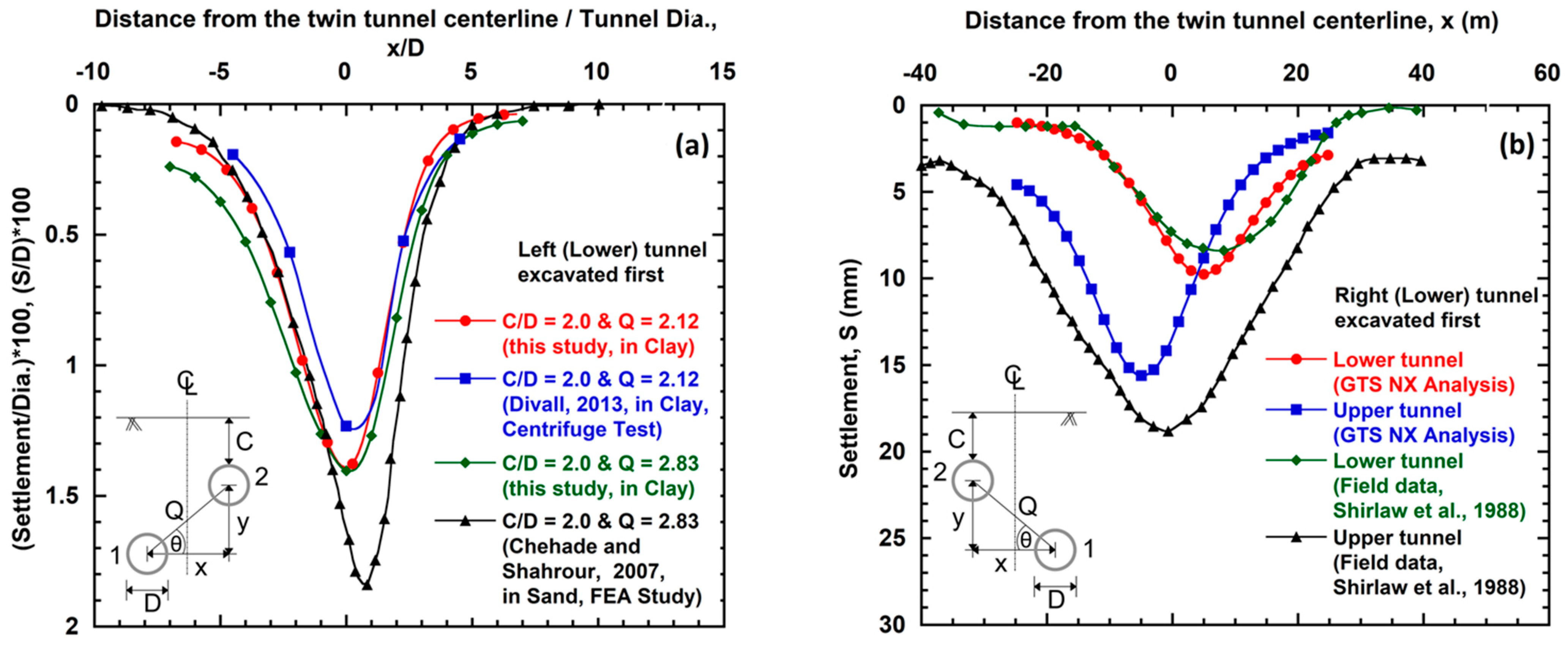
The settlement data obtained from this study are validated against data available in the literature and the data in Figure 7 show good agreement. While comparing the data from various studies, the similarities of geometric parameters, i.e., cover depth and angular spacing between two offset arrangement tunnels, were taken in account to conduct a valid comparison. FEM analysis results are compared in Figure 7a to previously reported centrifuge experiments [21] in clay and FE analysis [7] in sand. FEA analysis results are also compared in Figure 7b with a reported field observation [22] in stiff boulder clay on the Singapore Mass Rapid Transit. It can be seen from Figure 7a that offset arrangement twin tunnels of cover-to-diameter (C/D) ratio of 2.0 (for the upper tunnel) and angular spacing (Q) of 2.12 employed in this work yields similar settlements to those reported by Divall [21]. However, settlement for offset arrangement twin tunnels of C/D ratio of 2.0 (for the upper tunnel) and angular spacing of 2.83 in this study varies from the settlement observed by Chehade and Shahrour [7] in sand, whereas this study is performed in clay soil. In addition, it can be seen from Figure 7b that offset arrangement twin tunnels of C//D ratio of 2.0 and angular spacing (Q) of 2.04 show similar results for field observations compared with numerical analysis. These results suggest that the developed model can be used with confidence.
3. Interpretation of Results and Discussions
Ground displacements perpendicular to the tunnels’ axes at the end of the simulated excavation stages were extracted from the FEA model at the section coinciding with the tunnel face (y = 0 m). The influence of the model boundary conditions on the tunnel behavior at this section is believed to be negligible based on prior studies presented by Do et al. [23].
The behavior of twin tunnels during the excavation process of a new tunnel in the presence of an existing tunnel, and when both tunnels are excavated concurrently, is explored through a series of excavation stages. First, settlement induced after excavation of the first tunnel is presented. Next, settlement induced after the excavation of the second tunnel is also presented. Third, the combined settlement of both tunnels is presented for the case of staggered excavations. Finally, the combined settlement when both tunnels are excavated concurrently is also presented. The effect of various geometric parameters and excavation sequences on the computed settlement are investigated.
The magnitude of calculated settlement in this study is generally high and, in many cases, resulted in volume loss over 1%. Tunnels excavated with EPB or slurry shield machines where all tunnel operations parameters are simulated does not typically exceed 1% of volume loss. This difference could be attributed to the soft nature of the soil, which is also evident from the studies performed by Addenbrooke and Potts [10] and Chapman et al. [24] in undrained clays. Their work showed a larger volume loss ratio caused by the excavation of the second tunnel. Other reasons include simplification of the shield excavation and assumption of a low stiffness for the top soil layer in this study.
3.1. Effect of Angular Relative Position
Hefny et al. [25] describes the geometry of offset arrangement tunnels using the angular relative position angle, θ, of a new tunnel relative to an existing tunnel. The angle θ is measured between the center-to-center connecting line of two tunnels and the horizontal line drawn from the center of the lower tunnel (Figure 1). An angle of 90° represents a new tunnel directly above the crown or below the invert of an existing tunnel (vertically aligned tunnels or piggyback tunnels), while an angle of 0° represents a new tunnel located beside and at the same depth as the existing tunnel (horizontally aligned tunnels or side-by-side twin tunnels).
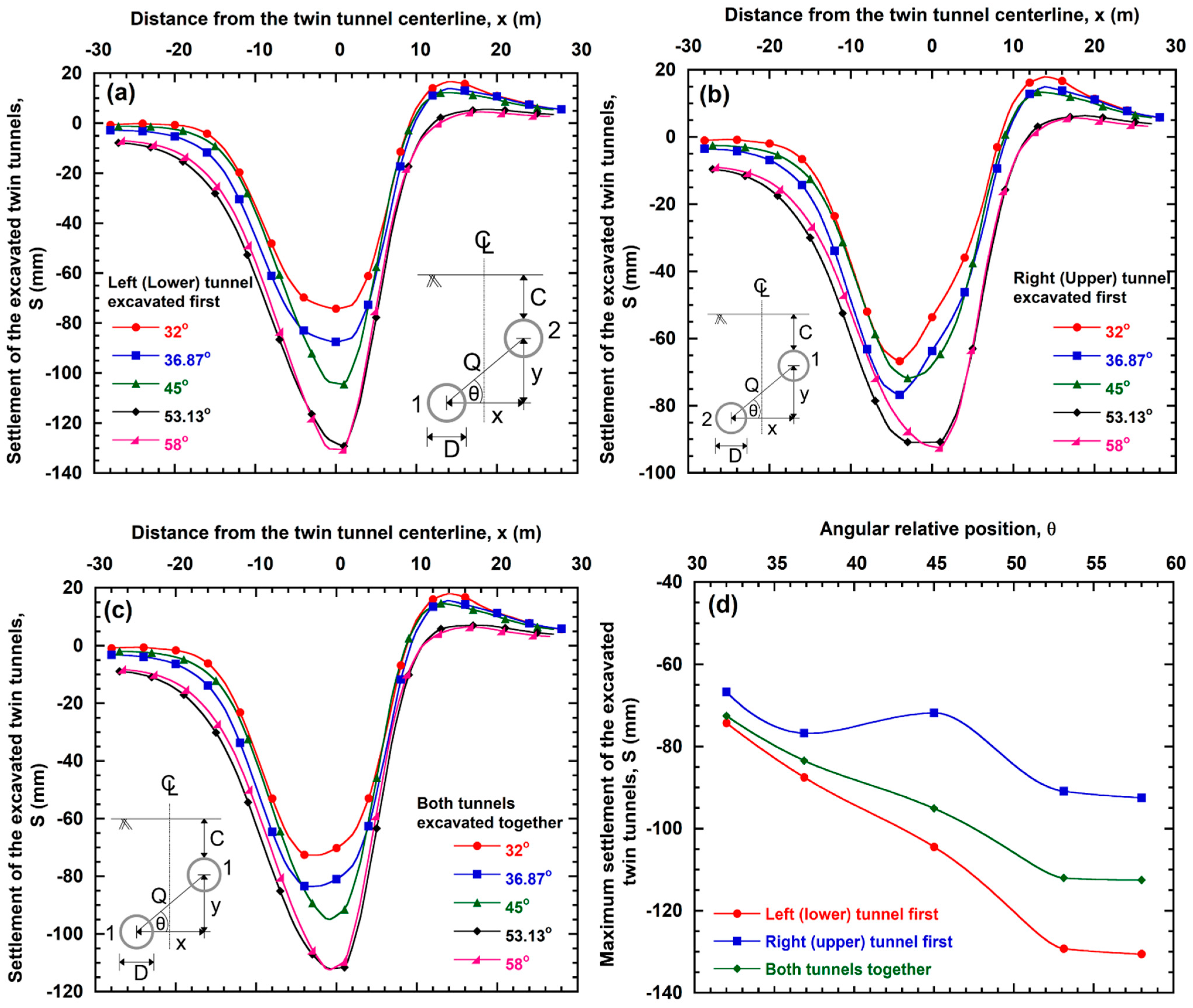
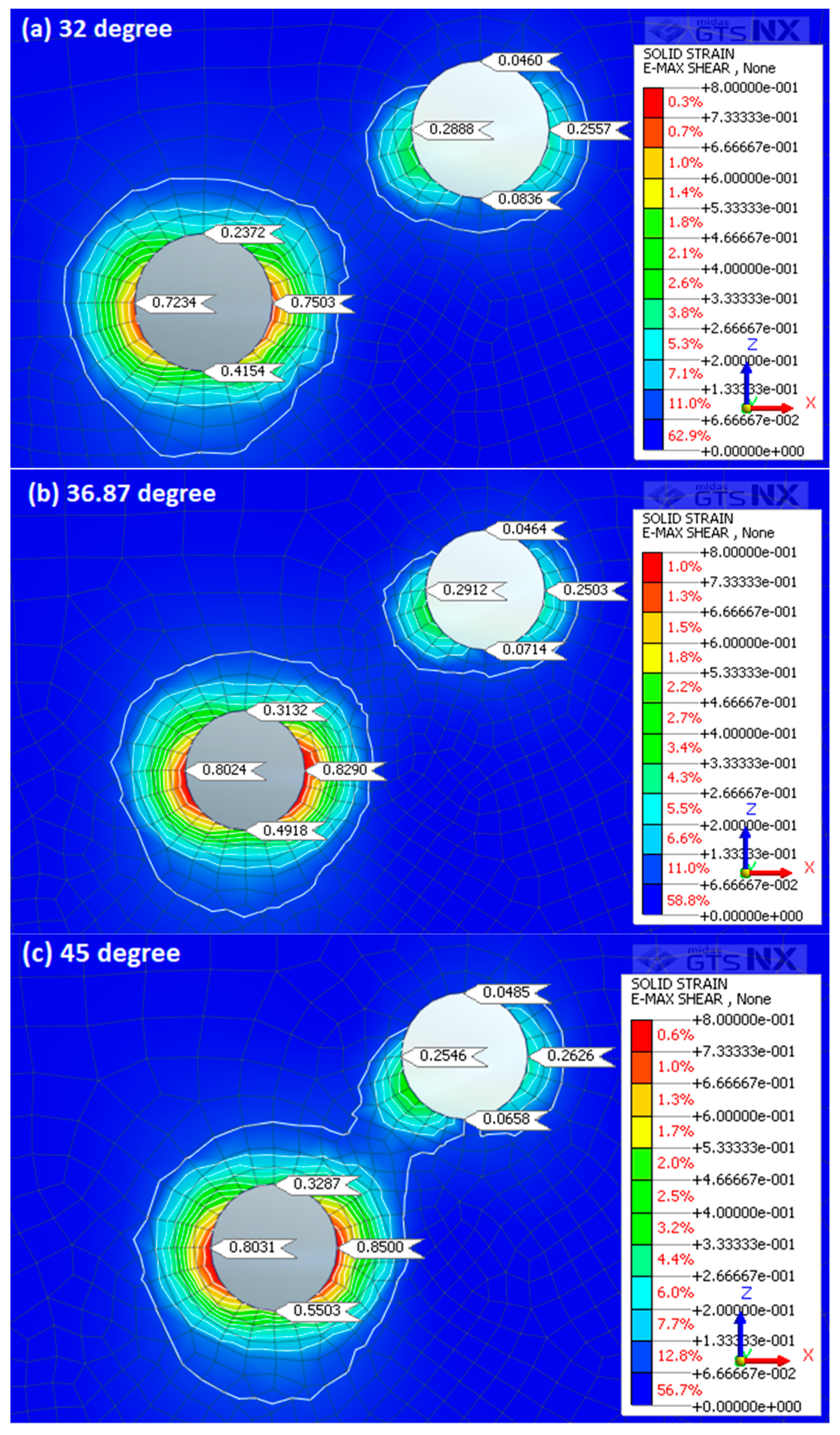
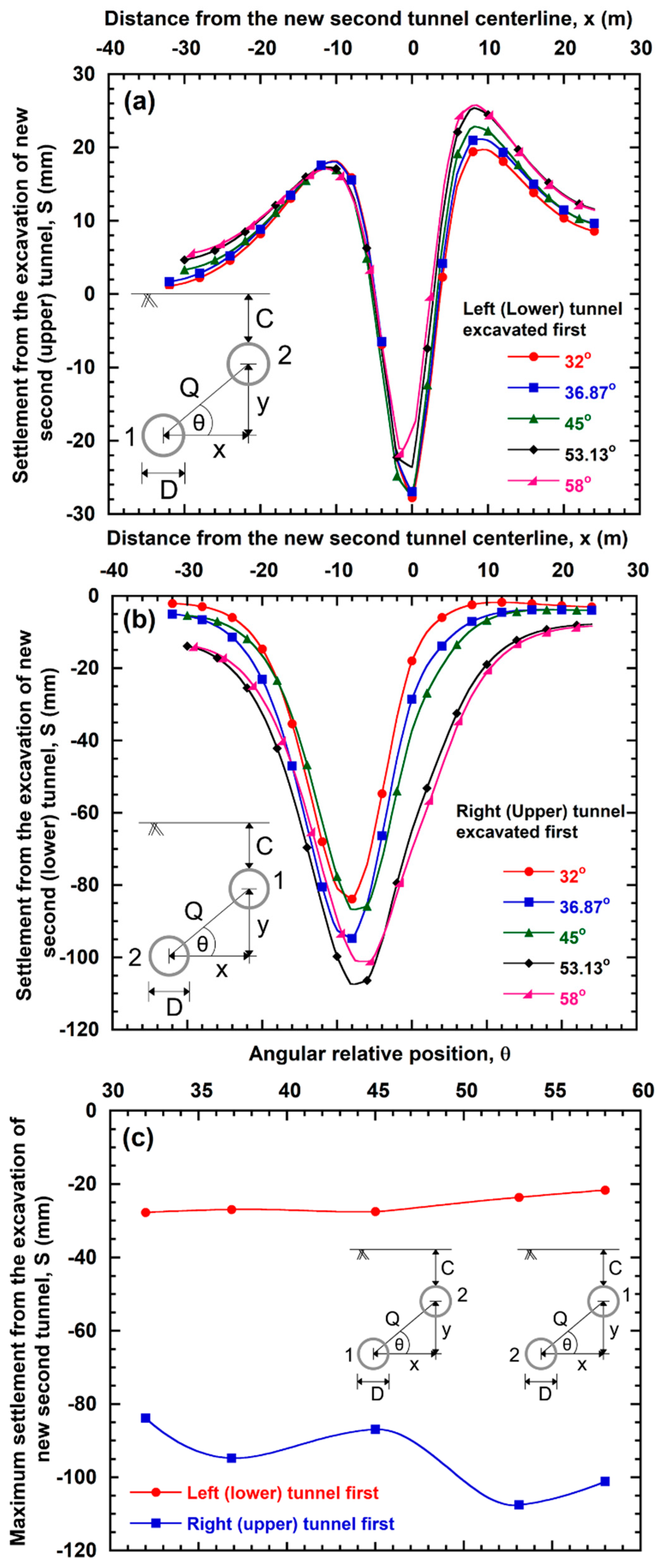
Settlement of the excavated twin tunnels for all three excavation sequences are plotted in Figure 8. Five different angular relative positions at a fixed cover-to-diameter ratio (C/D = 1.0) were considered in this study to investigate the effect of angular relative position. It is observed that, as the angle between the tunnels increase with respect to the horizontal axis, the surface soil settlement of the excavated twin tunnels increases for all construction sequences. This can be explained by the shear strain data presented in Figure 9, where increasing strain in the crown, invert, and springlines of the lower tunnel are observed with the increase in the magnitude of angular relative position. The reason for this is that the higher the magnitude of angular relative position, the more the new second upper tunnel falls within the influence zone of the lower tunnel. Lower tunnel excavation is the major contributor of the total settlement induced during excavation of offset arrangement twin tunnels. The relationship between the maximum observed soil settlement and the angular relative position is summarized in Figure 8d. The data suggest that a significant increase in settlement can be anticipated till θ reaches a certain magnitude (53.13° in this study), and then the increase slows down. However, since the increase in settlement is common to all three construction sequences, geometric position is believed to play a larger role.
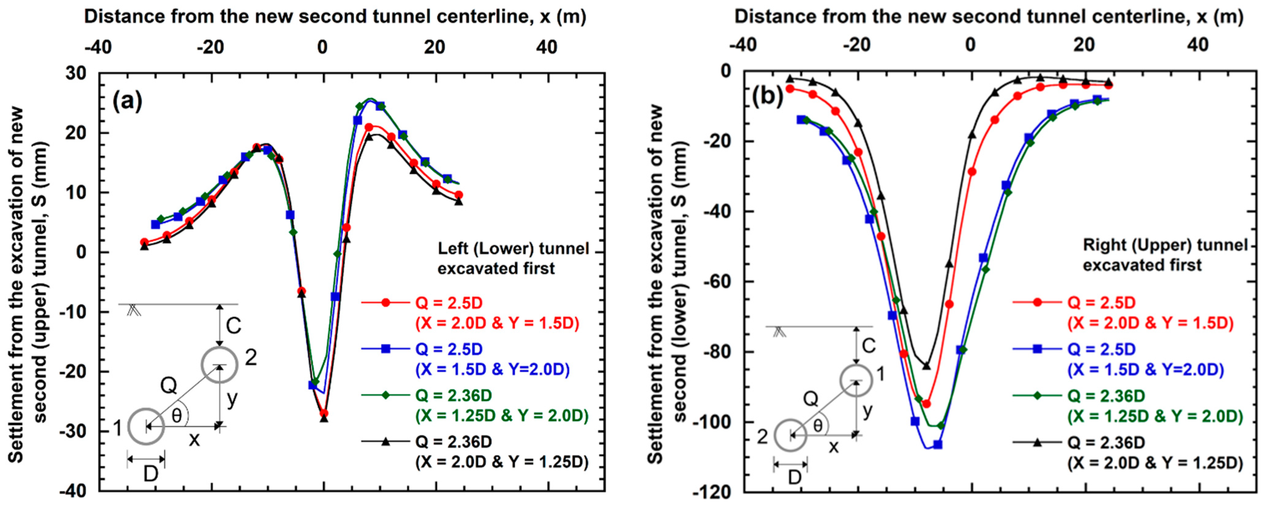
Settlement from the excavation of a new second tunnel is plotted in Figure 10a,b for both sequences when the lower tunnel is excavated first and when the upper tunnel is excavated first. Thus, Figure 10a,b represent settlement induced solely from the excavation of new upper tunnel and from the excavation of new lower tunnel, respectively. The observed trend of maximum settlement from the excavation of a new second tunnel is summarized in Figure 10c. It is noticed that as the angle between the tunnels increase with respect to the horizontal axis, the surface soil settlement induced by the new second tunnel excavation decreases when the lower tunnel is excavated first. The reason for this is that the higher the magnitude of the angular relative position, the more the new tunnel falls within the influence zone of the existing tunnel, which provide reinforcement support to the excavated new tunnel within its influence zone thus the new tunnel induces low settlement. This observation agrees well with the findings from Divall [21] and Channabasavaraj and Visvanath [26]. However, a distinct trend was not observed when the upper tunnel is excavated first, because the magnitude of observed upheaval when the upper tunnel is excavated first in undisturbed ground impacts the settlement induced by the lower second tunnel during its excavation. The high upheaval observed from the excavation of the shallower upper tunnel likely resulted from the low stiffness at top soil layers, as evident from Figure 3. Significant heave is not typically observed in in situ or in centrifuge tests. However, in numerical models, heave results from the use of a uniform modulus over the entire strain range. The inability of the employed constitutive model to account for higher stiffness at small strains and its rapid decay with increasing strains, as well as the dependence of the modulus on the past stress history, contributed to the observed heave. In this case, when the tunnel is excavated numerically, all soil elements below the invert arch follow an unloading stress path that is characterized by the same stiffness occurring in loading, making the computed heave proportional to the depth of the mesh bottom, and likely higher than what is observed physically.
3.2. Effect of Angular Spacing
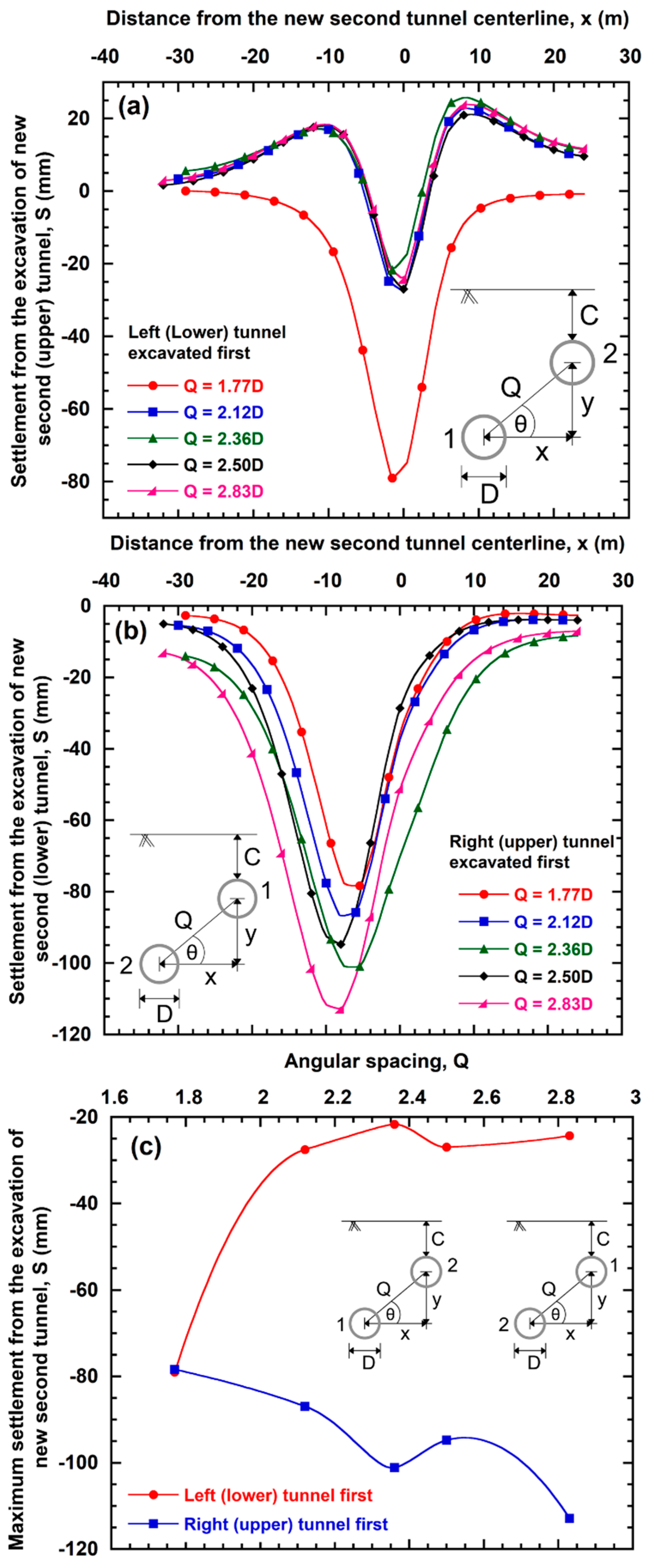
Tunnel offset is often described in terms of angular spacing, Q (Figure 1), although it is a less sensitive measure than the angular relative position, since distance does not always correlate with influence zone. Settlement from the excavation of a new second tunnel is plotted in Figure 11a,b for two excavation sequences, representing when the lower tunnel is excavated first and vice versa. Offset arrangement twin tunnels of five different angular spacings at a fixed cover-to-diameter ratio (C/D = 1.0) were modelled in this study to investigate the effect of angular spacings. Figure 11a,b represent settlement induced solely from the excavation of new upper tunnel and from the excavation of new lower tunnel, respectively. Generally, the larger the angular spacing, the larger the settlement induced from the excavation of the new lower tunnel when the upper tunnel is excavated first. The finding is consistent with the observation from numerical studies performed by Chehade and Shahrour [7] and experiments conducted by Divall [21]. The trough width becomes wider and deeper as the angular distance increases. The observed trend is summarized in Figure 11c, where the trend suggests opposite behavior depending on which the tunnel is excavated first. The smaller the angular spacing, the larger the settlement induced from the excavation of a new upper tunnel when the lower tunnel is excavated first. However, there appears to be a threshold represented by approximately Q > 2 where the settlement induced from the excavation of the new second upper tunnel is markedly less influenced by prior excavation as seen in Figure 11a.
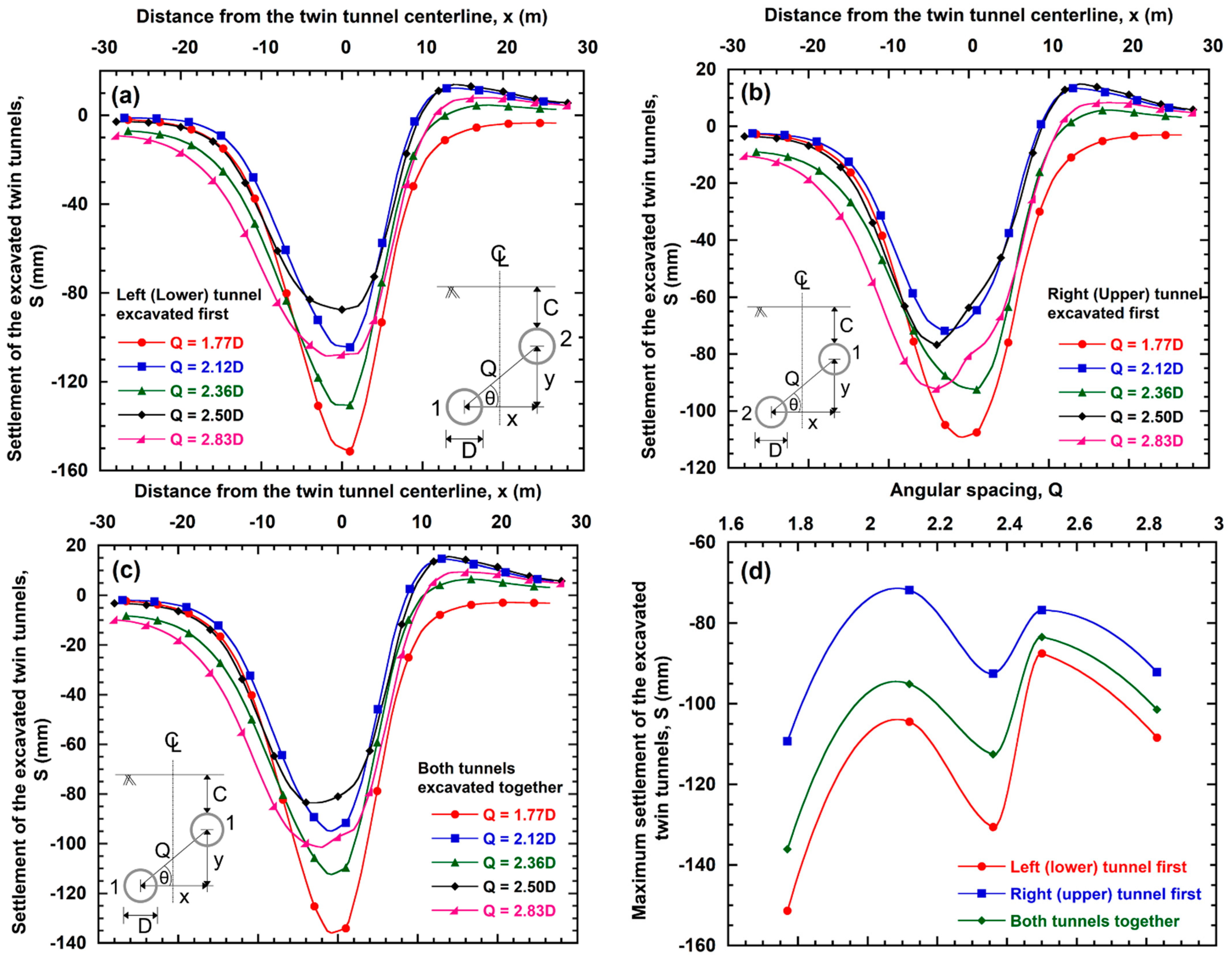
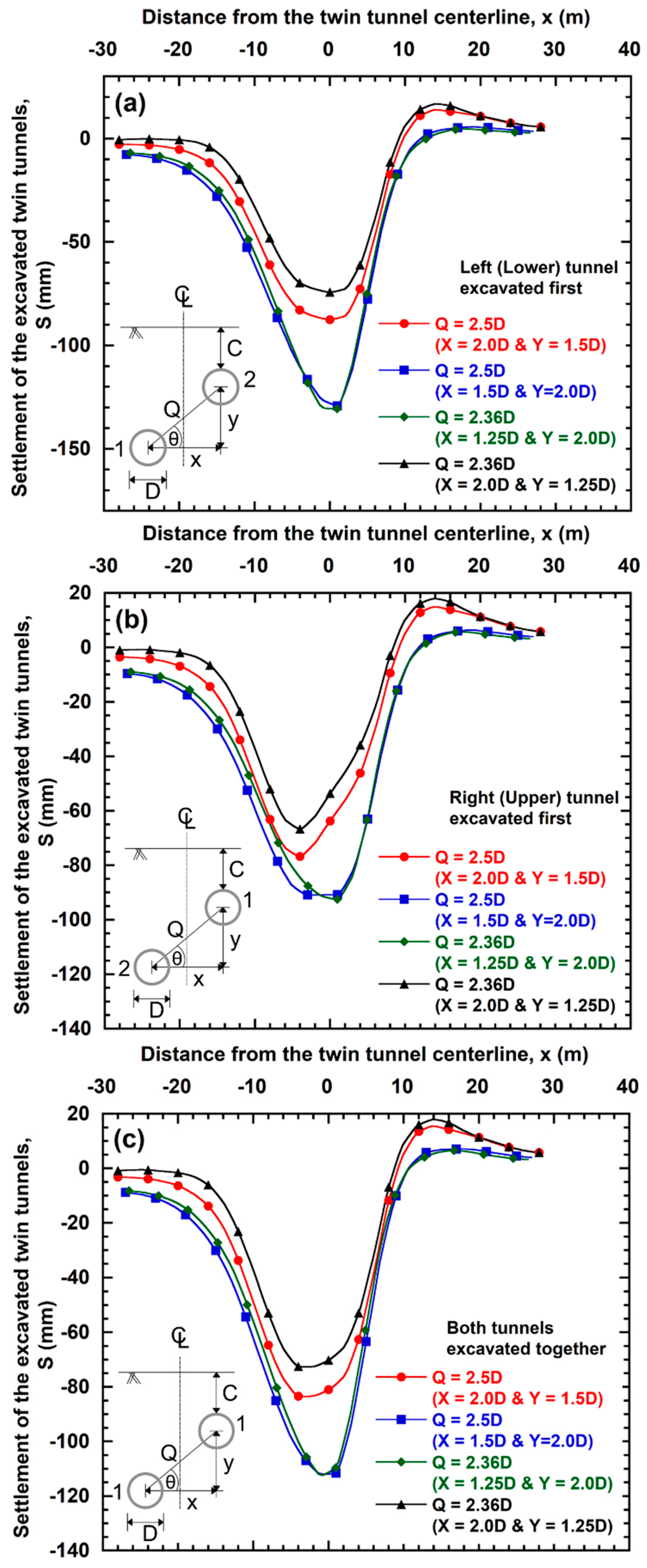
The combined settlement of the excavated twin tunnels for all three excavation sequences are plotted in Figure 12 for the five different angular spacings considered in this study. Generally, as the angular spacing between the tunnels decreases, the surface soil settlement of the excavated twin tunnels increases. However, it is not feasible to draw definitive conclusions, because twin tunnels having a specific angular distance can have different dimensions in the horizontal and vertical direction, which can exhibit different settlement behavior, as detailed below.
3.3. Effect of Horizontal and Vertical Distance When Angular Spacing Is Fixed
Angular spacing is a direct result of the horizontal and vertical distance between two tunnels. For two offset arrangement twin tunnels, the horizontal distance (X) and the vertical distance (Y) can be different while having the same angular spacing. To understand (i) the effect of the horizontal and vertical distances between two tunnels and (ii) whether the horizontal or vertical distance has significantly more impact on the tunnelling induced settlement at a fixed angular spacing and at a fixed C/D ratio, several analyses were performed, and the results are presented in Figure 13 and Figure 14. The effect of the horizontal and vertical distance on surface settlement above the new second tunnel in the presence of an existing tunnel at a fixed angular spacing is presented in Figure 13. It is evident that variation in X and Y has a significant effect on induced settlement, even though angular spacing remains the same. It can be seen from Figure 13b that a decrease in X and an increase in Y significantly increase the induced ground settlement of the new second tunnel when the upper tunnel is excavated first. The reason is that, with an increase in vertical distance, the possibility of the existing upper tunnel providing stiffness in the soil within the influence zone of the lower tunnel diminishes. On the contrary and as shown in Figure 13a, decrease in X and increase in Y decrease the induced ground settlement of the new second tunnel when the lower tunnel is excavated first. The effect of the horizontal and vertical distance on the total surface settlement caused by two offset arrangement twin tunnels at a fixed angular spacing is presented in Figure 14. Variation in the vertical distance Y while keeping the horizontal distance constant has significant effects on maximum surface settlement induced and on trough width, whereas variation of the horizontal distance X while keeping the vertical distance Y constant does not result in significant effects on the observed maximum surface settlement and demonstrates little to negligible effects on the trough width. Therefore, it can be concluded, with caution, that vertical distance Y has a more significant impact on the total induced settlement during the excavation of offset arrangement twin tunnels in comparison to the horizontal distance X. This is likely because vertical distance controls whether or not the upper tunnel will be within the influence zone of the lower first tunnel.
3.4. Effect of Cover-to-Diameter Ratio
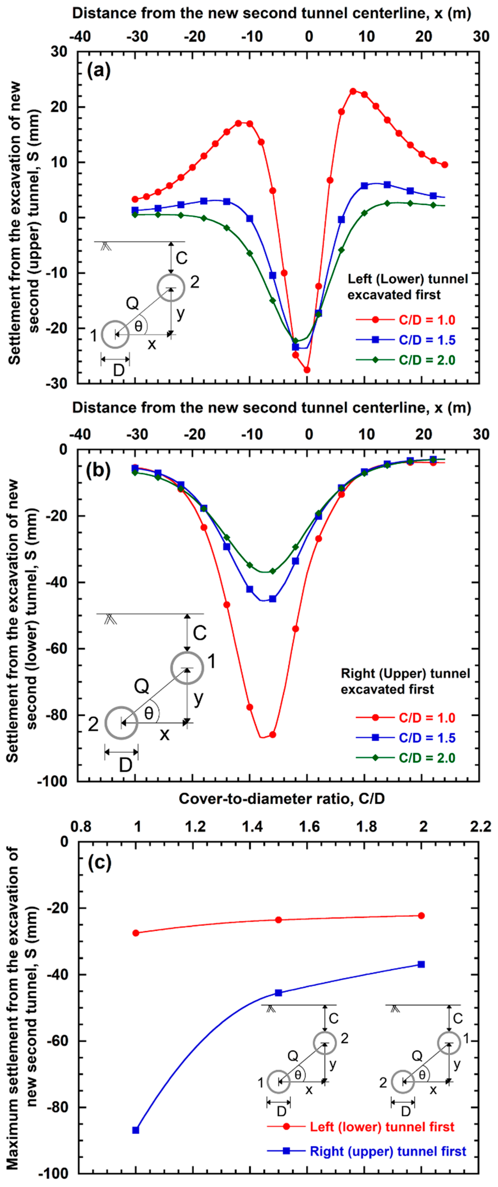
For single tunnels, Mair and Taylor [27], Marshall et al. [28], Ahmed and Iskander [29,30], and Ads et al. [31], among others, demonstrated that tunnelling induced settlement is larger when tunnelling occurred at a shallower depth (i.e., reducing C/D). Similarly, the magnitude of surface settlements for offset arrangement twin tunnels can be influenced not only by the spacing between the two tunnels but also by the cover depth of the tunnels. Settlements induced from the excavation of a new second tunnel in the presence of an existing tunnel for three cover-to-diameter (C/D) ratios are shown in Figure 15. All other geometric parameters (i.e., angular relative position, angular spacing, horizontal, and vertical distance) were kept constant to better understand the behavior solely attributed to the variation in C/D ratio. It is evident that, as the cover depths of the existing and new tunnels increase, settlement due to the new tunnel construction decreases irrespective of whether the new tunnel was excavated underneath or above the existing tunnel. This is because, with the larger C/D ratio, the increase in mobilized shear stiffness of the soil dominates the increase in stress relief caused by the tunnel excavation [32]. The data also suggest that the larger the cover depth, the wider the settlement trough and the more the position of maximum settlement shifted towards the existing tunnel.
The decrease in magnitude of settlement for the new second tunnel at increasing cover depths is much higher when the upper tunnel is excavated first than when the lower tunnel is excavated first. The reason for this is that the observed settlements from the construction of the lower tunnel are significantly higher than the settlement induced from the construction of the upper tunnel, regardless of the excavation sequence (Figure 16). When a new tunnel is excavated above an existing tunnel, the new tunnel heaves upward. This phenomenon is more evident when an upper tunnel is excavated at shallow cover depths, where the shallower the upper tunnel, the more the observed heave.
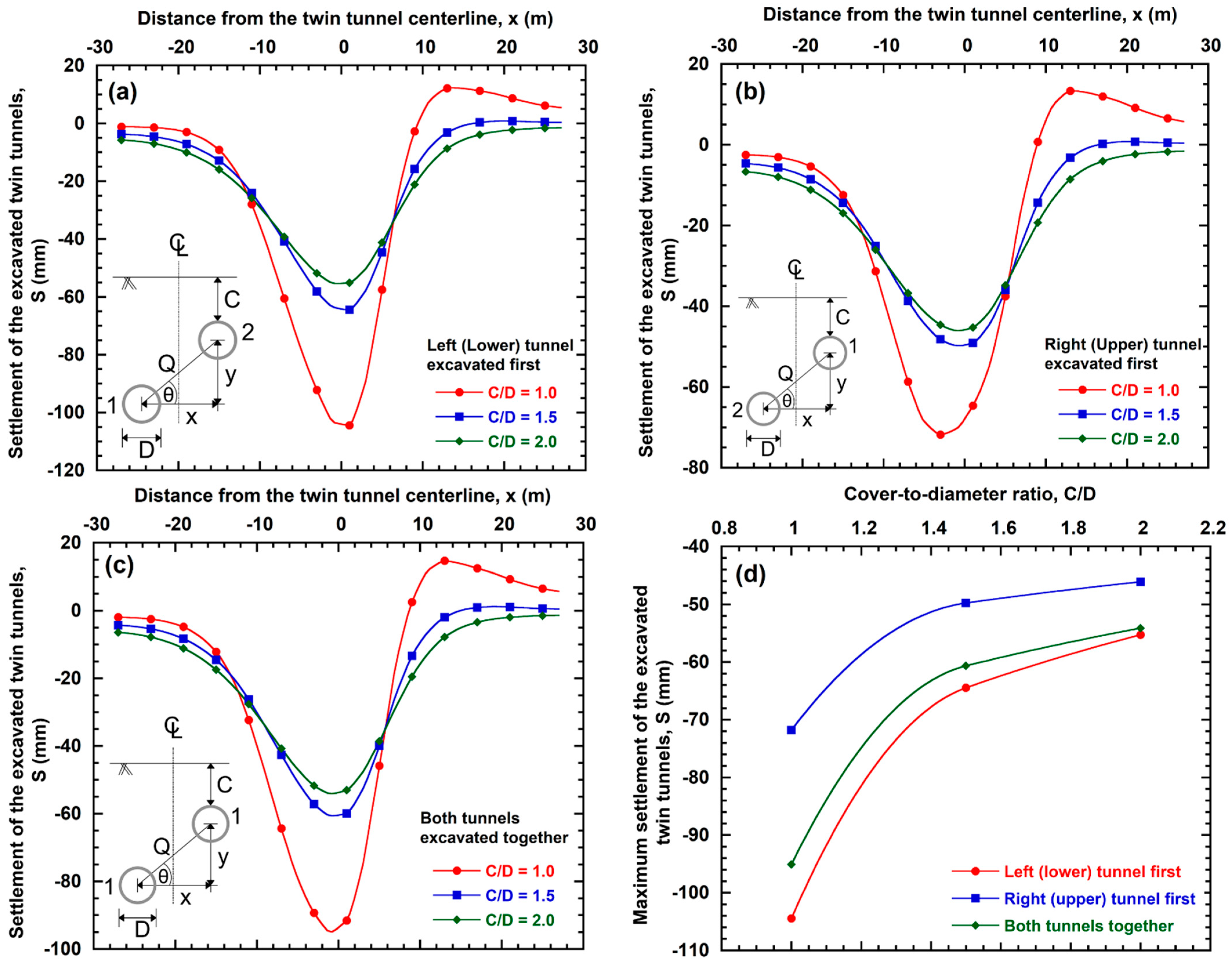
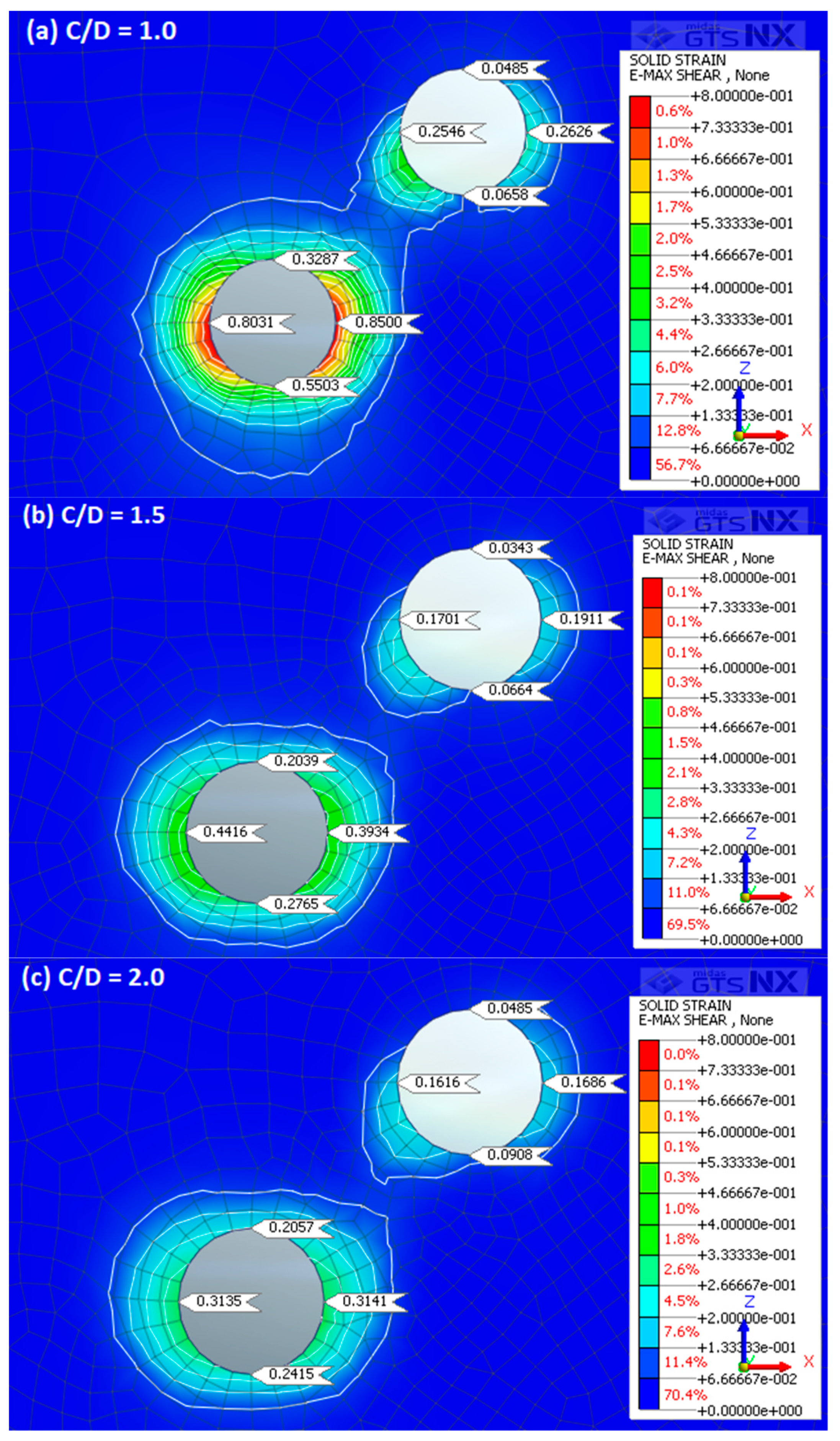
Total settlement induced from the excavation of twin tunnels for three C/D ratios and for three excavation sequences are shown in Figure 17a–c. The relationship between the maximum observed soil settlement and C/D ratios is summarized in Figure 17d. It is evident for all three construction sequences that the deeper the tunnels, the smaller the settlement. This settlement behavior is also evident from Figure 18 where shear strain data is shown for three C/D ratios and a trend of decreasing shear strain with the increase in C/D ratio can be seen. This is because, as the larger cover depths of the tunnels increase, the mobilized shear stiffness of the soil increases. Furthermore, the larger the cover depth, the wider the settlement trough and the more the position of maximum settlement is shifted towards the existing tunnel. However, the position of maximum settlement stays at or around the twin tunnel centerline when both tunnels are constructed concurrently. The data in Figure 17d also suggest that the magnitude of increase in settlement increases with the decrease in C/D ratios, regardless of the construction sequence.
3.5. Effect of Construction Sequence
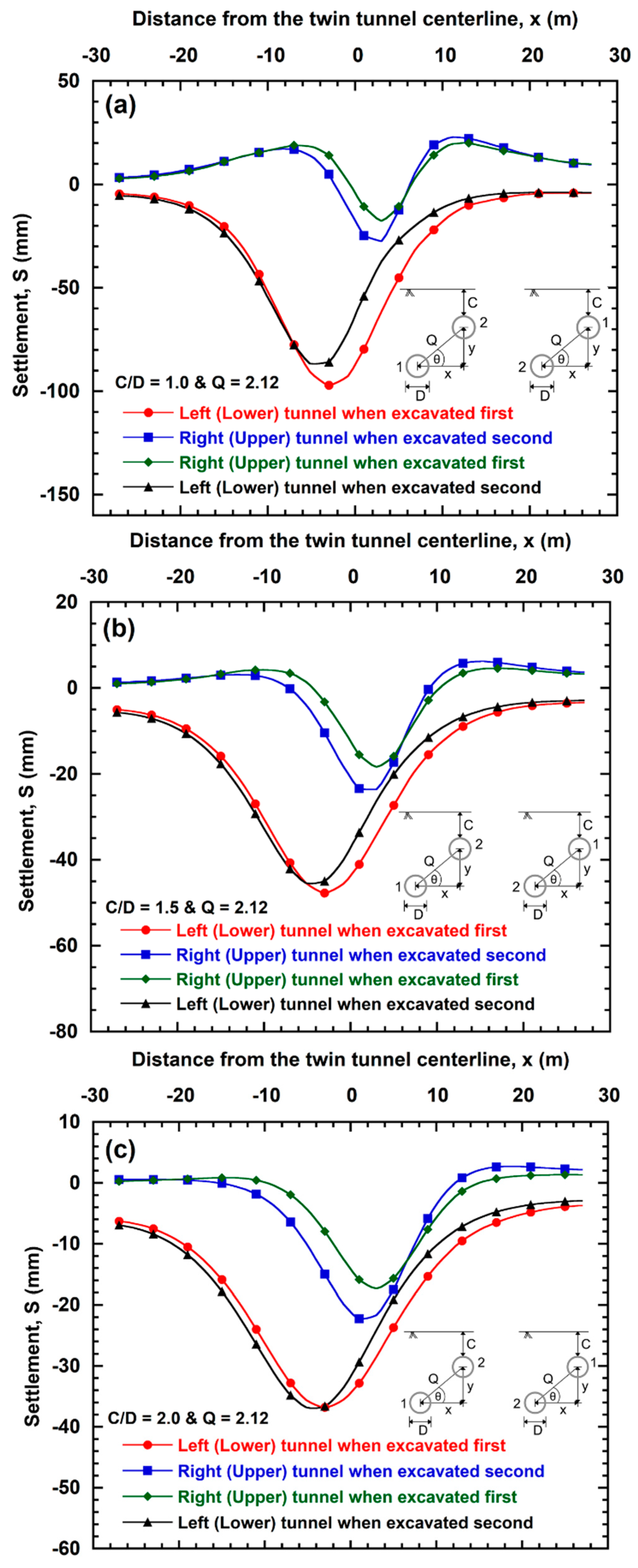
The influence of the construction sequence on the interaction of offset arrangement twin tunnels is complex. Individual settlement induced from both the lower and upper tunnel excavations when the lower tunnel is excavated first and vice versa are presented in Figure 16. The settlement trough was wider and deeper over the lower tunnel in both excavation sequences. Large settlement was observed during construction of the lower tunnels for any of the three cover-to-diameter (C/D) ratios, while relative upheaval was occasionally observed when the upper tunnels were excavated. The magnitude of the upheaval is slightly larger when the upper tunnel is excavated in a greenfield site than when it is excavated in a brownfield site, presumably because brownfield sites provide reinforcement support with the presence of an existing tunnel. It can also be seen from Figure 16 that excavation of the lower tunnel induces much larger settlement relative to the settlement induced by the upper tunnel, be it excavated first or excavated second. Therefore, it may be concluded that the primary dominant contributor to total settlement observed during the excavation of offset arrangement twin tunnels is always the lower tunnel. Yamaguchi et al. [33] also observed large subsidence during construction of the lower tunnels and relatively small subsidence during the upper tunnel excavation.
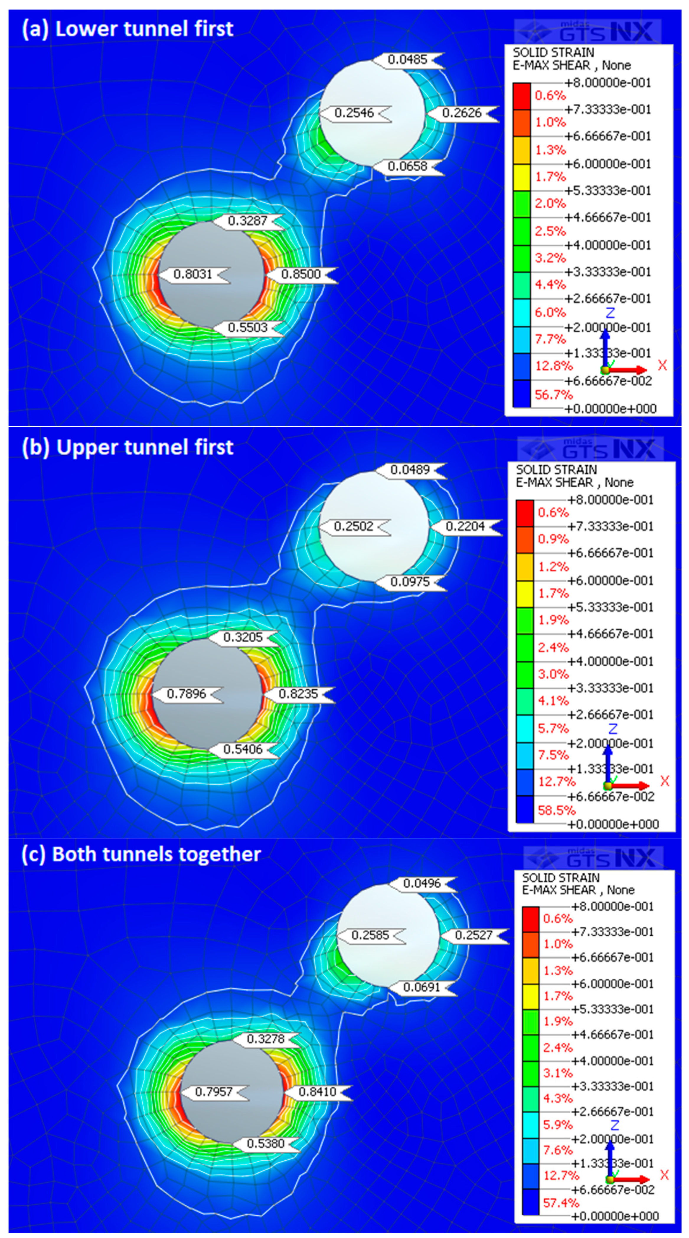
The combined settlement induced from the excavation of twin tunnels for three distinct cover-to-diameter (C/D) ratios are shown in Figure 19. Settlement data for all three possible construction sequences are presented. It can be observed that excavation of the left lower tunnel at first induces higher total ground settlement than when the right upper tunnel is excavated first, as well as when both lower and upper tunnel excavated concurrently. This settlement behavior can be explained from Figure 20 where shear strain data are shown for three excavation sequences. The induced shear strain is highest when the lower tunnel is excavated first and lowest when the upper tunnel is excavated first. When the lower tunnel is excavated first, the new upper tunnel would be constructed within the zone of movement of the lower tunnel and within soil which had been previously strained unless the new second upper tunnel is located at a considerable distance away from the lower tunnel. On the contrary, when the upper tunnel is excavated first, the zone of movement for the second lower tunnel is within both the previously strained soil disturbed by the upper tunnel excavation and the surrounding undisturbed soil. Chehade and Shahrour [7] observed similar settlement behavior that the construction of the lower tunnel at first leads to higher soil settlement than that induced when the upper tunnel is first constructed. It can also be seen from Figure 19 that the position of maximum settlement shifts towards the upper tunnel when the magnitude of the total settlement increases.
When the upper tunnel is constructed first, it provides stiffness within the soil and functions similarly to a shield above the new tunnel which results in a lower magnitude of settlement during the excavation of the lower tunnel. Furthermore, the disturbance resulting from the excavation of the first tunnel on the later tunnel occurs only in the overlapping influence zone, and the area outside this overlapping area is not affected by the disturbance. The induced disturbance when the upper tunnel is excavated first cannot impact the lower second tunnel much, as the lower tunnel is generally not within the overlapping influence zone. The opposite behavior is true when the lower tunnel is excavated first. It can thus be concluded that the effect of this previously strained soil within the influence zone on the profile above the second upper tunnel is more apparent when excavating the lower tunnel first.
4. Design Charts for Settlement Calculation Due to Excavation of a New Second Tunnel
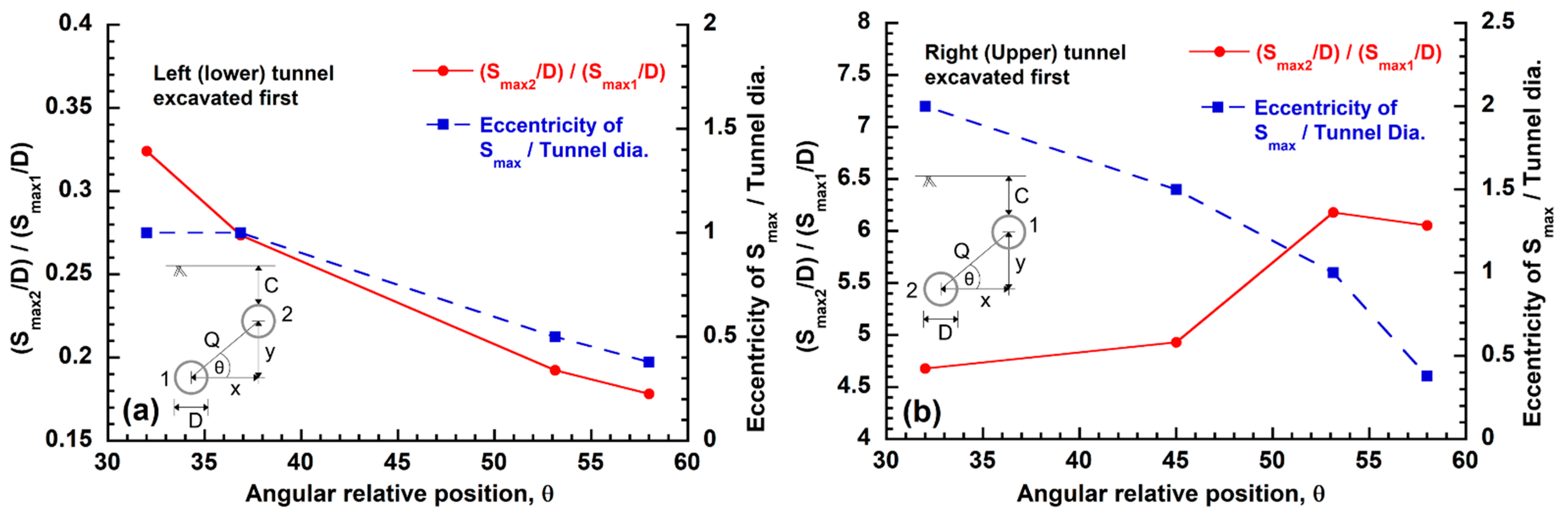
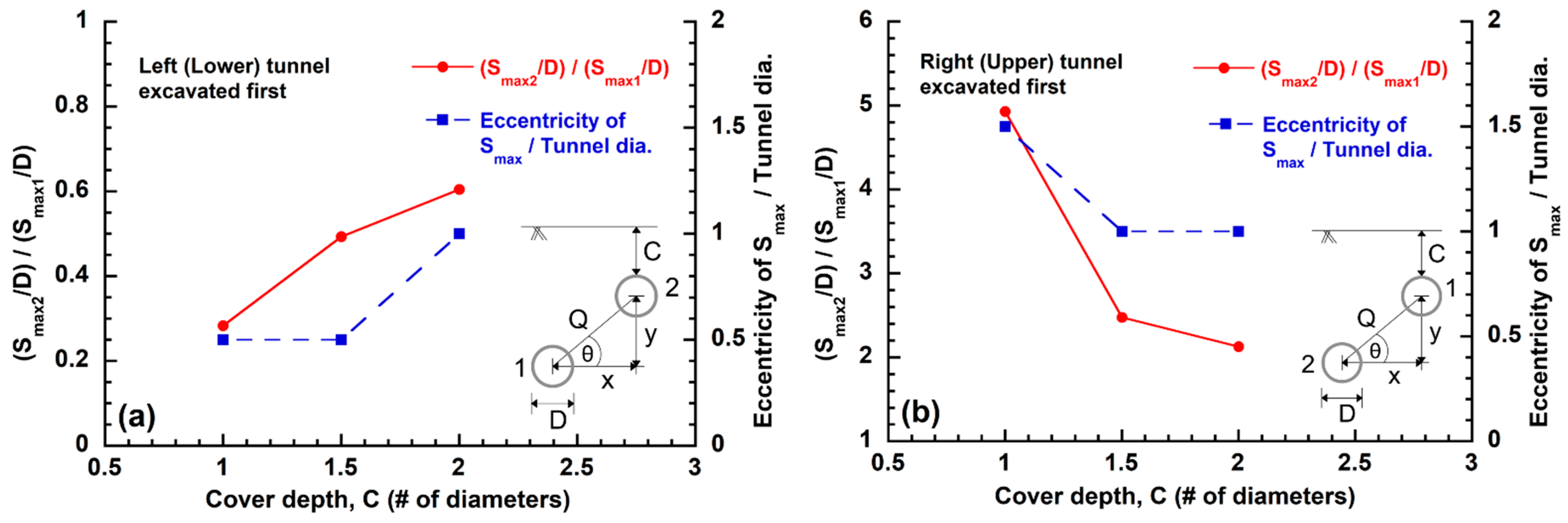
Two design charts have been prepared and presented in Figure 21 and Figure 22 to summarize the numerical observations. Both charts provide (a) the ratio of the second tunnel induced maximum settlement to the maximum settlement for a greenfield tunnel, and (b) the eccentricity of the maximum total settlement relative to the center of the new tunnel. One chart provides these data as a function of angular relative position, θ (Figure 21), while the second chart summarizes the information based on C/D ratio (Figure 22). The design charts suggest that the settlement resulting from the second tunnel can either increase or decrease depending on construction sequence and geometric parameters. The settlement resulting from the new second tunnel decreases with the increase in the magnitude of the angular relative position as shown in Figure 21 when the left lower tunnel is excavated first and vice versa, whereas the settlement resulting from the new second tunnel increases with the increase in the cover-to-diameter ratio as shown in Figure 22 when the left lower tunnel is excavated first and vice versa.
The design chart in Figure 22 also indicates that the eccentricity (distance between the new second tunnel centerline and the position of the maximum total settlement) can either increase or decrease with the increment in cover-to-diameter ratio depending on the construction sequence. However, the eccentricity always decreases with the increase in magnitude of angular relative position, as shown in Figure 21, regardless of the construction sequence.
Once the ratio of maximum settlement of the excavated second tunnel to the greenfield tunnel has been obtained from these design charts, the second tunnel settlement can be easily calculated using the greenfield tunnel settlement obtained using empirical formulas. The settlement induced from the second tunnel excavation can then be summed with the first tunnel settlement to predict the total settlement induced by the twin tunnel excavation. The design charts also help calculate the eccentricity, which is required to determine the position of the peak settlement trough relative to the position of both tunnels.
To verify the usefulness of the design charts, two additional FE analysis have been performed for C/D ratio 1.75, which is not part of the original parameter space used to develop the charts. One analysis is for the case when the lower tunnel is excavated first, and another analysis is for the case when the upper tunnel is excavated first. It can be observed from the design chart that for C/D ratio 1.75, the ratio of the maximum settlement of the excavated second tunnel to the greenfield tunnel are 0.55 and 2.29, respectively, when the lower tunnel is excavated first and when the upper tunnel is excavated first [Figure 22]. The ratios obtained using settlement data from FE analysis are 0.56 and 2.24, which are approximately equal to the values obtained from the design charts.
5. Limitations
This paper presents settlement data obtained from a set of numerical analysis performed for twin offset arrangement tunnels excavated in close proximity using MIDAS GTS NX, a commercial FEA package. The use of a simplified TBM excavation and reinforcing method, assuming low modulus of elasticity for the top layer of soil, and modelling of the upper tunnel at relatively shallow depth in clay introduce several limitations, as follows:
- The use of a simple Mohr–Coulomb constitutive model in the analysis is one of the main limitations, as previously discussed in Section 2.1 and Section 3.1. Use of the soft soil model in MIDAS GTS NX can better represent clay behavior, particularly during unloading as is the case in tunnel excavation. Nevertheless, the approach was selected for its simplicity and the parametric nature of the work where various configurations are compared to each other.
- The finite element model of tunnelling by removing gravitational forces corresponding to an initial stress-state tend to predict incorrect shape of ground settlement profiles at the extremities, where deformations due to small strains prevail. The use of a simplified constitutive hypotheses also impacts the shape and magnitude of ground settlement. Studies performed by Cheng et al. [34] and Zhang et al. [35], among others, demonstrated the effectiveness of displacement-controlled method that is capable to limit the movement of the lower portion of the tunnel, for a better prediction of the magnitude and shape of subsidence. Deformation controlled analyses require that the employed displacements be calibrated, but this was not possible in our case due to the lack of data from physical observations. In addition, a displacement-controlled model where displacements can be applied to nodes around the tunnel rather than by applying forces is time consuming for a parametric study and was thus not utilized here. In any case, the results presented focused on parametric comparison of peak settlements and are therefore less affected by the modeling of small strain moduli.
- The results presented herein are relevant to uniform clay profiles with tunnels having C/D < 2.5. For example, it can be seen from this study that the excavation of the lower tunnel at first leads to higher settlement. However, this behavior can be reversed when a tunnel is excavated at much deeper soil (i.e., if the C/D ratio is much higher) and when the top layer of the soil is stiffer. Use of a high modulus of elasticity for the top layer in the FEA model or modeling of deeper excavations will result in fewer settlements for the lower tunnel and reduced upheaval for the upper tunnel.
- The tunnels employed in this parametric study have similar diameters. However, twin tunnels can be of different diameters or shapes especially when an existing tunnel has been constructed decades ago. Variation in tunnel diameter can have little to significant impact on the induced ground settlements, as shown in Figure 6, for a single tunnel excavation. Thus, the results are likely to hold for cases where similar diameters are used for twin tunneling, but less so when tunnels having different diameters are employed.
- The proposed design charts are based on a limited number of analyses performed using FEA models and are only applicable for clay soils similar to the clay profile described in this study. The design charts can be improved with the performance of additional FE analysis at various C/D ratios, angular relative position scenarios, and for various clay profiles. FE analyses were compared to data available in peer reviewed literature; however, the paucity of available data makes this validation limited to a handful of FE analysis and experimental work.
6. Conclusions
This study explores the effect of excavation sequence and geometric parameters such as angular relative position, angular spacing, horizontal spacing, vertical spacing, and cover-to-diameter ratio on ground deformation induced in clay during the excavation of twin offset arrangement tunnels. The key results obtained and behaviors observed are as follows:
- The settlement trough was wider and deeper over the lower tunnel, whether excavated first or excavated second. When the upper tunnels were excavated, relative upheaval was generally observed. The magnitude of the upheaval is slightly larger when the upper tunnel is excavated in a greenfield site compared to when it is excavated in a brownfield site, presumably because brownfield sites provide reinforcement support due to the presence of an existing tunnel. It is also observed that the dominant contributor to the total settlement induced by the excavation of offset arrangement twin tunnels is always the lower tunnel.
- The position of the maximum total settlement is eccentrically displaced towards the new second tunnel, because a region of large strain concentration is believed to occur between the twin tunnels due to the excavation of the new second tunnel. The eccentricity decreases with increased cover depth as well as with the increase in distance (angular spacing) between the tunnels, although it is less definitive for the later.
- As the cover depths of the existing and new tunnels increase, settlement due to the excavation of the new tunnel decreases. Total settlement induced by the excavation of offset arrangement twin tunnels also decreases with the increase in cover-to-diameter (C/D) ratios. Furthermore, the larger the cover depth, the wider the settlement trough is and the more the position of maximum settlement is shifted towards the existing tunnel. However, the position of maximum settlement stays at or around the twin tunnel centerline when both tunnels are constructed concurrently.
- As the angle between the tunnels increases with respect to the horizontal axis, the surface soil settlement induced by the new second tunnel excavation decreases when the lower tunnel is excavated first. However, a distinct trend could not be identified when the upper tunnel is excavated first, because the magnitude of upheaval when the upper tunnel is excavated affects the settlement induced by the lower second tunnel.
- The settlement induced by the excavation of the new lower tunnel is generally larger with the increase in angular spacing when the upper tunnel is excavated first. On the contrary, it is generally observed, for all construction sequences, that as the angular spacing between the tunnels decrease, the total surface soil settlement of the excavated twin tunnels increases. However, a specific magnitude of angular distance can be represented by different dimensions in the horizontal and vertical directions, which can result in different settlement behavior. It can be concluded with caution that the vertical distance (Y) between two offset arrangement tunnels has a significant impact on the total surface settlement induced from the excavation of offset arrangement twin tunnels, whereas the horizontal distance (X) has little to negligible effects.
- The settlement profile is directly influenced by the construction sequence and the position of maximum settlement shifts towards the new upper tunnel when the magnitude of the total settlement increases. For example, the excavation of the lower tunnel at first induces higher total ground settlement than when the upper tunnel is excavated first as well as when both the lower and upper tunnels are excavated concurrently.
- The trough width of the settlement induced by the new second tunnel excavation and the total settlement induced from the twin tunnels excavation increase with the increase in angular relative position until it reaches a certain magnitude, then the trough width is generally stable and approximately constant. This behavior is not definitive for the changing angular spacing; however, it is a less sensitive parameter than the angular relative position since distance does not always correlate with influence zone.
Design charts are provided to aid with preliminary estimation of anticipated ground settlement due to the construction of twin tunnels. These charts can be used with caution in uniform clay profiles in undrained conditions where the cover-to-diameter ratio of upper tunnel is less than 2.5.
7. Author Biographies
Magued Iskandar is professor of geotechnical engineering and Chair of the Civil and Urban Engineering department at New York University Tandon School of Engineering. He has 30+ years of civil engineering experience including teaching, research, and consulting. Dr. Iskander holds a B.Sc. degree in Civil Engineering from Alexandria University and a Ph.D. degree in Civil (Geotechnical) Engineering from the University of Texas at Austin. He is a Fellow of the American Society of Civil Engineers (ASCE), an honor reserved for fewer than 5% of the society’s members. He is also a recipient of the prestigious National Science Foundation (NSF) Career Award. Dr. Iskander is a licensed Professional Engineers in New York, New Jersey, and Wisconsin. Professor Iskander authored 5 books, edited 11 books, and published over 200 papers including 90+ refereed journal articles dealing with tunneling, measurements, condition assessment, instrumentation, physical modeling, foundations, pedagogy, and urban geotechnology.
Md Shariful Islam is a PhD Candidate at the Department of Civil and Urban Engineering, New York University Tandon School of Engineering. He is a licensed Professional Engineer in the State of Michigan and New York. He is currently working as an Engineer-In-Charge with New York City Department of Transportation. Previously, he held various technical roles with New York City Transit Authority. He holds a B.Sc. Degree in Civil Engineering from Bangladesh University of Engineering and Technology, and a M.S. Degree in Civil Engineering from the City College of New York. He is a member of American Society of Civil Engineers and Municipal Engineers of New York. His professional experiences include analysis, design and construction support services for new tunnels and bridge construction projects as well as rehabilitation and reconstruction of the same. His research interests are focused on numerical modelling, soil-structure interaction and tunnelling induced ground settlements.
Author Contributions
M.S.I.: Investigation, Methodology, Formal analysis, Literature Review, Visualization, and Writing—Original Draft; M.I.: Conceptualization, Supervision, Validation, Writing—Review and Editing, Project administration, and Provision of Resources. All authors have read and agreed to the published version of the manuscript.
Funding
This research received no external funding.
Institutional Review Board Statement
Not applicable.
Informed Consent Statement
Not applicable.
Data Availability Statement
Data are available from the authors, upon reasonable request.
Acknowledgments
The authors would like to thank MIDAS Information Technology, USA for providing them with the necessary software for this research and technical support over the course of the study.
Conflicts of Interest
The authors declare no conflict of interest and certify that they have no affiliations with or involvement in any organization or entity with any financial interest (such as honoraria; educational grants; participation in speakers’ bureaus; membership, employment, consultancies, stock ownership, or other equity interest; and expert testimony or patent-licensing arrangements), or non-financial interest (such as personal or professional relationships, affiliations, knowledge or beliefs) in the subject matter or materials discussed in this manuscript.
References
- Choi, J.-I.; Lee, S.-W. Influence of existing tunnel on mechanical behavior of new tunnel. KSCE J. Civ. Eng. 2010, 14, 773–783. [Google Scholar] [CrossRef]
- Addenbrooke, T.I. Numerical Analysis of Tunnelling in Stiff Clay. Ph.D. Thesis, Imperial College, London, UK, 1996. [Google Scholar]
- Islam, S.; Iskander, M. Twin tunnelling induced ground settlements: A review. Tunn. Undergr. Space Technol. 2021, 110, 103614. [Google Scholar] [CrossRef]
- Fang, Q.; Tai, Q.; Zhang, D.; Wong, L.N.Y. Ground surface settlements due to construction of closely-spaced twin tunnels with different geometric arrangements. Tunn. Undergr. Space Technol. 2016, 51, 144–151. [Google Scholar] [CrossRef]
- Standing, J.R.; Nyren, R.J.; Longworth, T.I.; Burland, J.B. The measurement of ground movements due to tunnelling at two control sites along the Jubilee Line Extension. In Proceedings of the International Symposium on Geotechnical Aspects of Underground Construction in Soft Ground, London, UK, 15–17 April 1996; Mair, R.J., Taylor, R.N., Eds.; Balkema: Rotterdam, The Netherlands, 1996; pp. 751–756. [Google Scholar]
- Nyren, R.J. Field Measurements above Twin Tunnels in Clay. Ph.D. Thesis, Imperial College, London, UK, 1998. [Google Scholar]
- Chehade, F.H.; Shahrour, I. Numerical analysis of the interaction between twin-tunnels: Influence of the relative position and construction procedure. Tunn. Undergr. Space Technol. 2008, 23, 210–214. [Google Scholar] [CrossRef]
- Midas GTS NX 2019 (v2.1); MIDAS Information Technology Company, Ltd.: Seongnam-si, Korea, 2019.
- Zhang, Z.; Huang, M. Geotechnical influence on existing subway tunnels induced by multiline tunneling in Shanghai soft soil. Comput. Geotech. 2014, 56, 121–132. [Google Scholar] [CrossRef]
- Addenbrooke, T.I.; Potts, D.M. Twin Tunnel Interaction: Surface and Subsurface Effects. Int. J. Géoméch. 2001, 1, 249–271. [Google Scholar] [CrossRef]
- Galli, G.; Grimaldi, A.; Leonardi, A. Three-dimensional modelling of tunnel excavation and lining. Comput. Geotech. 2004, 31, 171–183. [Google Scholar] [CrossRef]
- Ieronymaki, E.S.; Whittle, A.J.; Sureda, D.S. Interpretation of Free-Field Ground Movements Caused by Mechanized Tunnel Construction. J. Geotech. Geoenviron. Eng. 2017, 143, 04016114. [Google Scholar] [CrossRef]
- Skempton, A.W. Discussion: The Planning and Design of New Hong Kong Airport; Institute of Civil Engineers: London, UK, 1957; Volume 7, pp. 305–307. [Google Scholar] [CrossRef] [Green Version]
- Bjerrum, L.; Simons, N.E. Comparison of shear strength characteristics of normally consolidated clays. Nor. Geotech. Inst. Publ. 1960, 35, 13–22. [Google Scholar]
- Janbu, N. Soil compressibility as determined by odometer and triaxial tests. In Proceedings of the European Conference on Soil Mechanics and Foundation Engineering (ECSMFE), Wiesbaden, Germany, 1963; pp. 19–25. [Google Scholar]
- Jaky, J. The coefficient of earth pressure at rest. J. Soc. Hung. Arch. Eng. 1944, 78, 355–358. [Google Scholar]
- Li, Y.Q.; Xie, K.H.; Zhou, J.; Kong, X.L. Analysis of the factors influencing foundation pit deformations. In Geotechnical Aspects of Underground Construction in Soft Ground; Ng, C.W.W., Huang, H.W., Liu, G.B., Eds.; CRC Press: Boca Raton, FL, USA, 2008; pp. 153–158. [Google Scholar]
- Anagnostou, G.; Kovári, K. Face stability conditions with earth-pressure-balanced shields. Tunn. Undergr. Space Technol. 1996, 11, 165–173. [Google Scholar] [CrossRef]
- Rijke, Q.C. Innovation of Stress and Damage Reduction in Bored Tunnels during Construction Based on a Shield Equilibrium Model. Ph.D. Thesis, Delft University of Technology and Holland Railconsult, Utrecht, The Netherlands, 2006. [Google Scholar]
- Mollon, G.; Dias, D.; Soubra, A.-H. Probabilistic analyses of tunneling-induced ground movements. Acta Geotech. 2013, 8, 181–199. [Google Scholar] [CrossRef] [Green Version]
- Divall, S. Ground Movements Associated with Twin-Tunnel Construction in Clay. Ph.D. Thesis, City University London, London, UK, 2013. [Google Scholar]
- Shirlaw, J.; Doran, S.; Benjamin, B. A case study of two tunnels driven in the Singapore ‘Boulder Bed’ and in grouted coral sands. Geol. Soc. London, Eng. Geol. Spéc. Publ. 1988, 5, 93–103. [Google Scholar] [CrossRef]
- Do, N.-A.; Dias, D.; Oreste, P.; Djeran-Maigre, I. Three-dimensional numerical simulation for mechanized tunnelling in soft ground: The influence of the joint pattern. Acta Geotech. 2014, 9, 673–694. [Google Scholar] [CrossRef]
- Chapman, D.N.; Ahn, S.K.; Hunt, D.V. Investigating ground movements caused by the construction of multiple tunnels in soft ground using laboratory model tests. Can. Geotech. J. 2007, 44, 631–643. [Google Scholar] [CrossRef]
- Hefny, A.M.; Chua, H.C.; Jhao, J. Parametric studies on the interaction between Existing and new bored tunnels. Tunn. Undergr. Space Technol. 2004, 19, 471. [Google Scholar]
- Channabasavaraj, W.; Visvanath, B. Influence of relative position of the tunnels: A Numerical study on twin tunnels. In Proceedings of the 7th International Conference on Case Histories in Geotechnical Engineering, Chicago, IL, USA, 29 April–4 May 2013. [Google Scholar]
- Mair, R.J.; Taylor, R.N. Bored tunnelling in the Urban environment. In Proceedings of the 14th International Conference on Soil Mechanics and Foundation Engineering, Hamburg, Germany, 6–12 September 1997; pp. 2353–2385. [Google Scholar]
- Marshall, A.; Farrell, R.; Klar, A.; Mair, R. Tunnels in sands: The effect of size, depth and volume loss on greenfield displacements. Géotechnique 2012, 62, 385–399. [Google Scholar] [CrossRef]
- Ahmed, M.; Iskander, M. Analysis of Tunneling-Induced Ground Movements Using Transparent Soil Models. J. Geotech. Geoenviron. Eng. 2011, 137, 525–535. [Google Scholar] [CrossRef]
- Ahmed, M.; Iskander, M. Evaluation of tunnel face stability by transparent soil models. Tunn. Undergr. Space Technol. 2012, 27, 101–110. [Google Scholar] [CrossRef]
- Ads, A.; Islam, S.; Iskander, M. Effect of Face Losses and Cover-to-Diameter Ratio on Tunneling Induced Settlements in Soft Clay, Using Transparent Soil Models. Geotech. Geol. Eng. 2021, 39, 5529–5547. [Google Scholar] [CrossRef]
- Boonyarak, T.; Ng, C.W. Effects of construction sequence and cover depth on crossing-tunnel interaction. Can. Geotech. J. 2015, 52, 851–867. [Google Scholar] [CrossRef] [Green Version]
- Yamaguchi, I.; Yamazaki, I.; Kiritani, Y. Study of ground-tunnel interactions of four shield tunnels driven in close proximity, in relation to design and construction of parallel shield tunnels. Tunn. Undergr. Space Technol. 1998, 13, 289–304. [Google Scholar] [CrossRef]
- Cheng, C.; Dasari, G.; Chow, Y.; Leung, C. Finite element analysis of tunnel–soil–pile interaction using displacement controlled model. Tunn. Undergr. Space Technol. 2007, 22, 450–466. [Google Scholar] [CrossRef]
- Zhang, Z.; Huang, M.; Zhang, M. Deformation analysis of tunnel excavation below existing pipelines in multi-layered soils based on displacement controlled coupling numerical method. Int. J. Numer. Anal. Methods Géoméch. 2012, 36, 1440–1460. [Google Scholar] [CrossRef]
Figure 1.
Offset arrangement twin tunnels. (a) Lower tunnel is excavated first, and (b) upper tunnel is excavated first.
Figure 1.
Offset arrangement twin tunnels. (a) Lower tunnel is excavated first, and (b) upper tunnel is excavated first.

Figure 2.
Typical (a) plan view, and (b) cross-section of the offset arrangement twin tunnels excavation sequence used in the study (not to scale).
Figure 2.
Typical (a) plan view, and (b) cross-section of the offset arrangement twin tunnels excavation sequence used in the study (not to scale).

Figure 3.
Effect of Young’s modulus of elasticity on tunnelling induced ground settlement (initial E0 shown).
Figure 3.
Effect of Young’s modulus of elasticity on tunnelling induced ground settlement (initial E0 shown).

Figure 4.
Mesh in the FEM twin tunnel model (ID #1). (a) Perspective view of the mesh of the entire model, and (b) zoomed view of the mesh around the twin tunnels.
Figure 4.
Mesh in the FEM twin tunnel model (ID #1). (a) Perspective view of the mesh of the entire model, and (b) zoomed view of the mesh around the twin tunnels.

Figure 5.
Effect of unsupported excavation length (UEL) on tunnelling induced ground settlement.

Figure 6.
Effect of tunnel diameter on tunnelling induced ground settlement.

Figure 7.
Model validation: (a) comparison between normalized total settlement of offset arrangement twin tunnels observed in this study and in similar published studies, (b) comparison of field observed settlement data with FEM analyses for two offset arrangement twin tunnels.
Figure 7.
Model validation: (a) comparison between normalized total settlement of offset arrangement twin tunnels observed in this study and in similar published studies, (b) comparison of field observed settlement data with FEM analyses for two offset arrangement twin tunnels.

Figure 8.
Effect of angular relative position on (a–c) combined surface settlement caused by the excavation of offset arrangement twin tunnels and (d) maximum total surface settlement of the twin tunnels.
Figure 8.
Effect of angular relative position on (a–c) combined surface settlement caused by the excavation of offset arrangement twin tunnels and (d) maximum total surface settlement of the twin tunnels.

Figure 9.
Effect of angular relative position on shear strain in the crown, invert, and springlines of twin tunnels at the end of excavation (a–c).
Figure 9.
Effect of angular relative position on shear strain in the crown, invert, and springlines of twin tunnels at the end of excavation (a–c).

Figure 10.
Effect of angular relative position on (a,b) surface settlement above the new second tunnel and (c) maximum settlement from the excavation of the new second tunnel.
Figure 10.
Effect of angular relative position on (a,b) surface settlement above the new second tunnel and (c) maximum settlement from the excavation of the new second tunnel.

Figure 11.
Effect of angular spacing on (a,b) surface settlement above the new second tunnel and (c) maximum settlement from the excavation of the new second tunnel.
Figure 11.
Effect of angular spacing on (a,b) surface settlement above the new second tunnel and (c) maximum settlement from the excavation of the new second tunnel.

Figure 12.
Effect of angular spacing on (a–c) combined surface settlement caused by the excavation of offset arrangement twin tunnels and (d) maximum total surface settlement of the twin tunnels.
Figure 12.
Effect of angular spacing on (a–c) combined surface settlement caused by the excavation of offset arrangement twin tunnels and (d) maximum total surface settlement of the twin tunnels.

Figure 13.
Effect of the horizontal and vertical spacing on surface vertical settlement above the new second tunnel in the presence of an existing tunnel at a fixed angular spacing (a,b).
Figure 13.
Effect of the horizontal and vertical spacing on surface vertical settlement above the new second tunnel in the presence of an existing tunnel at a fixed angular spacing (a,b).

Figure 14.
Effect of the horizontal and vertical spacing on the total surface settlement induced by offset arrangement twin tunnels at a fixed angular spacing (a–c).
Figure 14.
Effect of the horizontal and vertical spacing on the total surface settlement induced by offset arrangement twin tunnels at a fixed angular spacing (a–c).

Figure 15.
Effect of cover-to-diameter ratio on (a,b) surface settlement above the new second tunnel and (c) maximum settlement from the excavation of the new second tunnel.
Figure 15.
Effect of cover-to-diameter ratio on (a,b) surface settlement above the new second tunnel and (c) maximum settlement from the excavation of the new second tunnel.

Figure 16.
Individual surface vertical settlement induced by both first and second tunnels during staggered excavation of offset arrangement twin tunnels (a–c).
Figure 16.
Individual surface vertical settlement induced by both first and second tunnels during staggered excavation of offset arrangement twin tunnels (a–c).

Figure 17.
Effect of cover-to-diameter ratio on (a–c) combined surface settlement caused by two offset arrangement twin tunnels, and (d) maximum total settlement of the excavated twin tunnels.
Figure 17.
Effect of cover-to-diameter ratio on (a–c) combined surface settlement caused by two offset arrangement twin tunnels, and (d) maximum total settlement of the excavated twin tunnels.

Figure 18.
Effect of cover-to-diameter ratio on shear strain in the crown, invert, and springlines of twin tunnels at the end of excavation (a–c).
Figure 18.
Effect of cover-to-diameter ratio on shear strain in the crown, invert, and springlines of twin tunnels at the end of excavation (a–c).

Figure 19.
Effect of excavation sequence on total surface settlement caused by offset arrangement twin tunnels (a–c).
Figure 19.
Effect of excavation sequence on total surface settlement caused by offset arrangement twin tunnels (a–c).

Figure 20.
Effect of construction sequence on shear strain in the crown, invert, and springlines of twin tunnels at the end of excavation (a–c).
Figure 20.
Effect of construction sequence on shear strain in the crown, invert, and springlines of twin tunnels at the end of excavation (a–c).

Figure 21.
Design chart for preliminary estimation of the ratio of the maximum settlement of the excavated second tunnel to a greenfield tunnel and the eccentricity of the maximum total settlement relative to the center of the new second tunnel. (a) Lower tunnel excavated first, (b) upper tunnel excavated first.

Figure 22.
Design chart for preliminary estimation of the ratio of the maximum settlement of the excavated second tunnel to the greenfield tunnel and the eccentricity of the maximum total settlement relative to the center of the new tunnel. (a) Lower tunnel excavated first, (b) upper tunnel excavated first.


Table 1.
Geometries of twin tunnels used in the finite element analyses.
| ID | Cover Depth, C | Horizontal Distance, x (D) | Vertical Distance, y (D) | Angular Spacing, Q (D) | Angular Relative Position, θ |
|---|---|---|---|---|---|
| 1 | 1.0 | 1.5 | 1.5 | 2.12 | 45 |
| 2 | 1.5 | 1.5 | 1.5 | 2.12 | 45 |
| 3 | 2.0 | 1.5 | 1.5 | 2.12 | 45 |
| 4 | 1.0 | 2.0 | 2.0 | 2.83 | 45 |
| 5 | 1.0 | 2.0 | 1.5 | 2.50 | 36.87 |
| 6 | 1.0 | 1.25 | 1.25 | 1.77 | 45 |
| 7 | 1.0 | 1.5 | 2.0 | 2.50 | 53.13 |
| 8 | 1.0 | 1.25 | 2.0 | 2.36 | 58 |
| 9 | 1.0 | 2.0 | 1.25 | 2.36 | 32 |
Table 2.
Material parameters adopted in the finite element analyses.
| Material Parameters | Clay Soil | Lining Segment |
|---|---|---|
| Unit weight (kN/m3) | 18.0 | 24.0 |
| Saturated density (kN/m3) | 20.0 | 25.2 |
| Initial Void ratio, e0 | 0.5 | - |
| Coefficient of permeability (m/s) | 1e-5 | - |
| K0 | 0.7412 | 1 |
| Elastic modulus, E (kN/m2) | 2000 + 1500 z 1 | 2.1e7 |
| Undrained poisson’s ratio, ν | 0.495 | - |
| Friction Angle, φ (°) | 15 | - |
| Cohesion, c (kN/m2) | 25 | - |
| Drainage conditions | Undrained | Drained |
1 z, depth below the ground surface (in meters).
Table 3.
Pressure parameters used in the finite element analyses to model TBM excavation.
| Pressure Parameters | Magnitude |
|---|---|
| Face support pressure | 180 kN/m2 |
| Jack thrust | 4500 kN/m2 |
| Shield external pressure | 50 kN/m2 |
| Segment external pressure | 1000 kN/m2 |
Publisher’s Note: MDPI stays neutral with regard to jurisdictional claims in published maps and institutional affiliations. |
© 2022 by the authors. Licensee MDPI, Basel, Switzerland. This article is an open access article distributed under the terms and conditions of the Creative Commons Attribution (CC BY) license (https://creativecommons.org/licenses/by/4.0/).
Share and Cite
MDPI and ACS Style
Islam, M.S.; Iskander, M. Effect of Geometric Parameters and Construction Sequence on Ground Settlement of Offset Arrangement Twin Tunnels. Geosciences 2022, 12, 41. https://0-doi-org.brum.beds.ac.uk/10.3390/geosciences12010041
AMA Style
Islam MS, Iskander M. Effect of Geometric Parameters and Construction Sequence on Ground Settlement of Offset Arrangement Twin Tunnels. Geosciences. 2022; 12(1):41. https://0-doi-org.brum.beds.ac.uk/10.3390/geosciences12010041
Chicago/Turabian StyleIslam, Md Shariful, and Magued Iskander. 2022. "Effect of Geometric Parameters and Construction Sequence on Ground Settlement of Offset Arrangement Twin Tunnels" Geosciences 12, no. 1: 41. https://0-doi-org.brum.beds.ac.uk/10.3390/geosciences12010041
Note that from the first issue of 2016, this journal uses article numbers instead of page numbers. See further details here.