Architecture of Glaciotectonic Complexes

Geological Survey of Denmark and Greenland (GEUS), Øster Voldgade 10, DK 1350 Copenhagen K, Denmark
Geosciences 2014, 4(4), 269-296; https://0-doi-org.brum.beds.ac.uk/10.3390/geosciences4040269
Submission received: 16 June 2014
/
Revised: 17 September 2014
/
Accepted: 30 September 2014
/
Published: 16 October 2014
(This article belongs to the Special Issue Geological Mapping and Modeling of Earth Architectures)
Abstract
:Glaciotectonic studies are an integrated part of the Quaternary geological research carried out by the Danish geological survey. Almost all the hilly areas in Denmark were created or affected by glaciotectonic deformations, and the features are included in the mapping of surface near deposits. For the mapping and support of constructing 3D geological models a classification of architecture of glaciotectonic complexes is suggested. The important elements for classification of architecture are the surfaces. Four orders of surfaces are defined for glaciotectonic complexes: first-order surfaces are décollement surfaces and glaciotectonic unconformities; second-order surfaces are ramps and flats—the thrust faults; third-order surfaces are folded beds—anticlines and synclines; and fourth-order surfaces are small scale folds and faults—kink bands, conjugate faults, box folds, etc. The most important first-order surface is the décollement surface. This surface limits the glaciotectonic complex at its base and controls the extent of glaciotectonic disturbances. Below this surface, ordinary flat lying planar bedding occurs, whereas above the surface a number of structures are present characteristic of second- to fourth-order elements in the glaciotectonic architecture. The other first-order surface is the topographic top of the glaciotectonic complex, which eventually may be replaced by a truncating unconformity.
1. Introduction
Denmark is part of the low land area of southern Scandinavia, which repeatedly served as a “dump area” for glacial deposits during the Pleistocene glaciations. The main dynamic in the glacial setting was ruled by the accumulation of snow and ice in the Scandinavian mountain ranges and a subsequent gravity gliding of the ice cap towards Northern Europe (Figure 1). A suggestion for a glaciodynamic sequence stratigraphy for these settings as well as for similar settings in North America and former glaciation areas related to ancient ice cap fields was proposed by Pedersen [1]. The deposition in the glaciodynamic sequences of Pedersen [1] was mainly related to the proglacial development, which due to the progressive advance of the ice front resulted in glaciotectonic deformation and creation of glaciotectonic complexes. The size of these complexes is up to 100 km2 with a depth down to 300 m. Superimposed glaciotectonic deformation and setting of glaciotectonic complexes caused by periodically re-advances during retreat of the ice margin will be addressed in the discussion. Among terrains affected by glaciotectonics Denmark and its surrounded shallow seas is probably the most intensely glaciotectonically deformed region in the world [2,3,4]. Therefore, glaciotectonic studies are an integrated part of the Quaternary geological research carried out by the Danish geological survey (GEUS). The focus of these studies is to understand the architecture of the glaciotectonic complexes for the support of constructing 3D geological models, which are applied in raw material investigation, groundwater research and areal planning in general. A number of former classifications of glaciotectonism are based on geomorphology and glacial geology dynamics [5,6]. In this presentation a classification is suggested for the internal structure of glaciotectonic complexes, which is here regarded as their architecture. The contribution describes the glaciotectonic architectural elements, and various examples of glaciotectonic features, mainly from Danish sites, are presented. The contribution aims at clarifying the definition and application of architecture in glaciotectonic complexes.
2. Classification of the Main Architectural Elements in Glaciotectonics
The inspiration for clarifying the meaning and use of the term architecture is taken from the use of architectural analysis of sedimentary deposits. The concept of hierarchical bounding surfaces in sedimentary deposits was initially applied in aeolian deposits [7] and in a study of fluvial deposits [8]. The concept of fluvial architecture was launched by Andrew Miall in 1985 and became widely adopted. He introduced a new approach to the description and interpretation of fluvial deposits: A limited number of architectural elements separated by a hierarchy of bounding surfaces were sufficient for the description of a large variety of fluvial deposits [9,10]. The architectural analysis of fluvial deposits may range from detailed studies of modern deposits [11] to the multiple fill of an incised valley [12] to mention just two of innumerable studies.
The application of the concept of fluvial architecture in an actual outcrop may present a number of difficulties, especially in the recognition of the bounding surfaces of intermediate rank in outcrops of limited size. The large-scale bounding surfaces may be recognized in geophysical data and their 3D framework may be mapped in seismic surveys [13,14,15] or by electromagnetic measurements (SKYTEM) [16,17,18].
Figure 1.
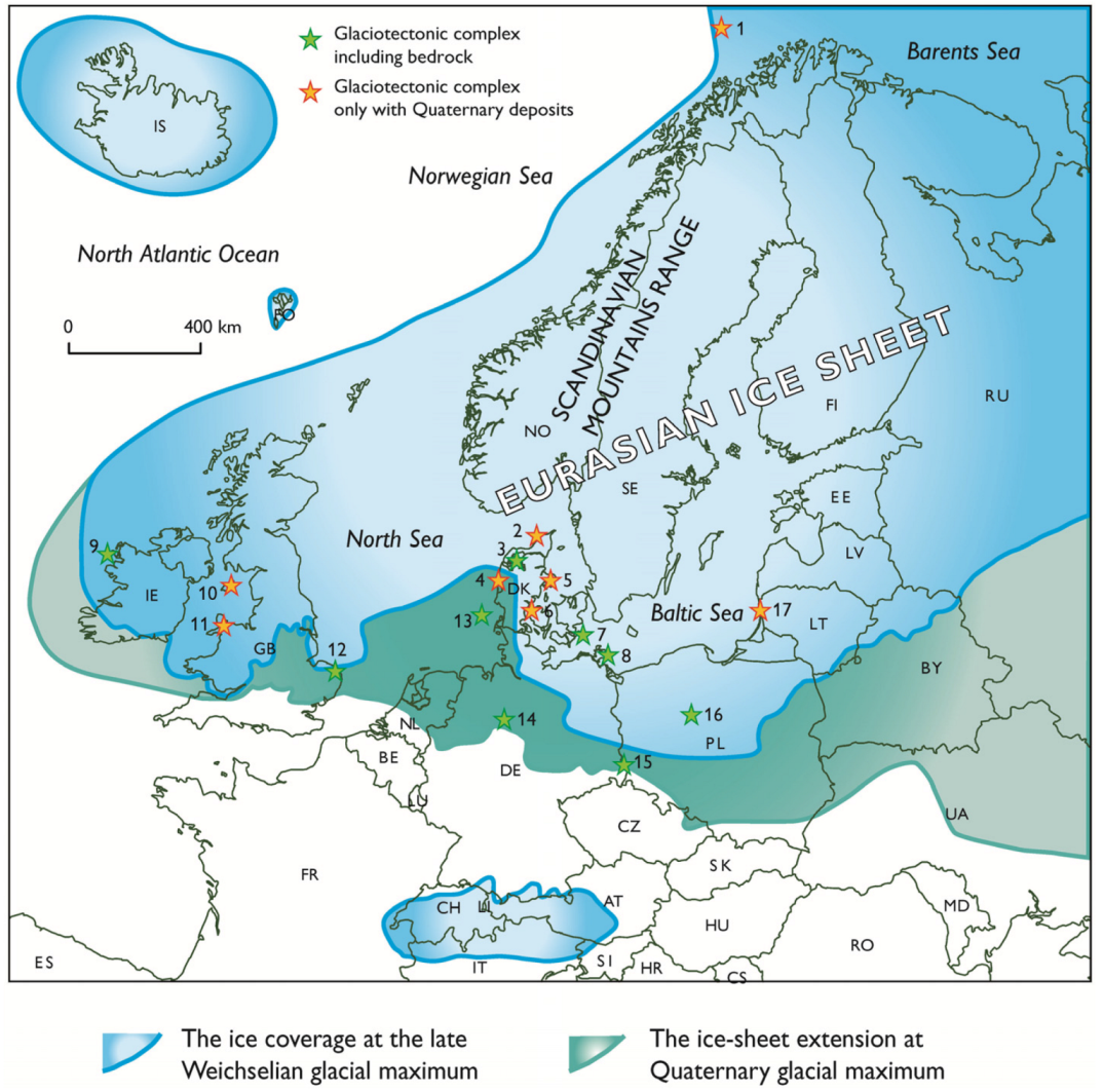
Map of the ice coverage in Northern Europe during the Pleistocene glaciations. The boundary of the Eurasian Ice Sheet is modified from Svendsen et al. [19]. A representativenumber of glaciotectonic complexes are located with reference numbers; 1: Barents Sea [20], 2: Rubjerg Knude, northern Denmark [4], 3: Limfjorden, northern Denmark [21,22,23,24], 4: Bovbjerg, the Weichselian Main Stationary Line at the North Sea coast in Denmark [25], 5: Djursland, central Denmark [1,26], 6: Halk Hoved, southern Denmark [27], 7: Møns Klint, SE Denmark [24,28], 8: Rügen, northern Germany [29,30,31], 9: Killana, NW Ireland [32], 10: Isle of Man, UK [33,34], 11: Dinas Dinlle, northern Wales, UK [33], 12: Cromer, Norfolk, eastern England [35,36,37], Fanø Bugt, offshore SW coast Denmark [2], 14: Berlinger Berge, central Germany [33], 15: Muskau-Faltenbogen, southern border between Poland and Germany [38,39], 16: Kleczew graben, central Polish Lowland [40], 17: Klaipeda, Baltic coast of Lithuania [41].
Figure 1.
Map of the ice coverage in Northern Europe during the Pleistocene glaciations. The boundary of the Eurasian Ice Sheet is modified from Svendsen et al. [19]. A representativenumber of glaciotectonic complexes are located with reference numbers; 1: Barents Sea [20], 2: Rubjerg Knude, northern Denmark [4], 3: Limfjorden, northern Denmark [21,22,23,24], 4: Bovbjerg, the Weichselian Main Stationary Line at the North Sea coast in Denmark [25], 5: Djursland, central Denmark [1,26], 6: Halk Hoved, southern Denmark [27], 7: Møns Klint, SE Denmark [24,28], 8: Rügen, northern Germany [29,30,31], 9: Killana, NW Ireland [32], 10: Isle of Man, UK [33,34], 11: Dinas Dinlle, northern Wales, UK [33], 12: Cromer, Norfolk, eastern England [35,36,37], Fanø Bugt, offshore SW coast Denmark [2], 14: Berlinger Berge, central Germany [33], 15: Muskau-Faltenbogen, southern border between Poland and Germany [38,39], 16: Kleczew graben, central Polish Lowland [40], 17: Klaipeda, Baltic coast of Lithuania [41].

The most important classification elements in architecture are the surfaces. For the glaciotectonic complexes the hierarchy of surfaces follows the order from macro to minor forms similar to the approach for dunes and aeolian deposits by Brookfield [7]. Thus four orders of surfaces are identified and defined for glaciotectonic complexes:
- First-Order surfaces are décollement surfaces and glaciotectonic unconformities.
- Second-Order surfaces are ramps and flats—the thrust faults.
- Third-Order surfaces are folded beds—anticlines and synclines
- Fourth-Order surfaces are small scale folds and faults—kink bands, conjugate faults, box folds, etc.
The most important first order surface is the décollement surface. This surface limits the glaciotectonic complex at its base and indicates the lower boundary of the extent of glaciotectonic disturbances. Below this surface, ordinary flat lying planar bedding occur—or at least glaciotectonically undeformed deposits will be present, whereas above the surface a number of structures are present characteristic of second- to fourth-order elements in the glaciotectonic architecture. The other first-order surface is also the upper limit of the glaciotectonic complex. If the pro-glacially deformed complex is a recent formation along an ice margin, or if a pre-existing complex had never been truncated by the advancing ice, the surface will be the topography of the up thrust and folded sheets of the complex subjected to general erosion, e.g., in neoglacial ice-pushed ridges in Iceland [42], Spitsbergen [43] and Greenland [44]. However, the majority of preserved glaciotectonic complexes from the Pleistocene were truncated by the advancing ice that created the complex, or by a subsequent advance/readvances, or even penecontemporaneous erosion during the deposition of contemporary outwash sequences. At the base of the translating ice, shear deformation created drag folds, which are superimposed by a cataclastic breccia—the glacitectonite. During the ice advance, a lodgement till were typically deposited above the glacitectonite, sometimes with a gradually transition, and this deformational layer comprises the second first order surface.
The second-order surfaces are the thrust faults. These form the boundaries of the individual segments building up a complex. The geometry of ramps and flats can be interpreted from detachment folds, and duplexes may create complex repetitions of the geological successions. Note that it is important to differentiate between hanging-wall thrusts and foot-wall thrusts, comprising the upper and lower side, respectively, of a thrust fault. The relation between the structures in the hanging-wall block and the thrust is dynamically a different story than the simple relation between the thrust and the truncated footwall block [4].
The third-order surfaces are the folds. It can be demonstrated that the anticlines can help the construction of the depth to the décollement surface, and large-scale fold structures can be related to, and help reconstruct the geometry of larger scale thrust systems at depth. Hanging-wall anticlines predict the existence of foot-wall ramps and the bending of beds up along a ramp creates monoclines.
The fourth-order of surface comprises small scale structures, which are important for the prediction of dynamic development. Anastomosing joints indicates early deformation impact, and zone axis of conjugate faults indicates direction of compaction. The asymmetry of small and mesoscale folds and sense of displacement on faults indicated by groove marks can be used to reconstruct the kinematics of deformation, which in turn records the direction of ice advance. Also parasitic small-scale folds, bedding-cleavage relationship and listric fault-splay fans can be used to identify the presence of large-scale fold structures.
Concerning classification on a large scale the glaciotectonic complexes can be differentiated into a distal, a central and a proximal domain. In the description of the architecture these three items clarify the relation to the foreland—the distal zone, the bulk architecture of the complex—the central zone, and the limiting part of the complex towards the hinterland—the proximal zone. In the latter the complexity of deformation increases, and mud mobilization and diapirism may add to occurrence of chaotic structures.
3. The First-Order Architectural Surfaces
In general the first-order surfaces only comprise two architectural elements: the décollement surface at the base of the complex and the topographic surface or the buried erosional unconformity at the top of the complex. The décollement surface forms the main boundary of the deformation down into the subsurface. This basal décollement surface (thrust) accommodates the bulk of the displacement during glaciotectonism allowing the progressive shortening of the sedimentary sequence in its hanging-wall in response to compressional deformation. The top topographic surface is in recent glaciotectonic complexes the hilly geomorphology of the pushed ridges in front of the ice margin (Figure 2). However, in concealed glaciotectonic complexes the top surface will often constitute a glaciotectonic unconformity or it may be replaced by an ordinary erosional unconformity.
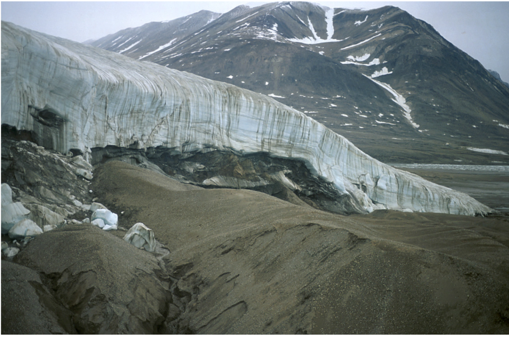
Figure 2.
The second first-order surface is the upper limit of the glaciotectonic complex. In a recent pro-glacially deformed complex the surface will be the topography of the up thrust and folded sheets of the complex, which are subjected to general erosion. This is here illustrated by the recent glaciotectonic complex at the margin of the Holm Lands Isbræ, a local ice cap in NE Greenland. The dashed lines outline the thrust faults in an imbricate fan, a typical second-order type of surfaces in the glaciotectonic architecture. Photo SASP 1995.

3.1. The Décollement Surface
The basal first-order surface in the glaciotectonic complex is the décollement surface. The décollement, or basal detachment surface, limits the glaciotectonic complex at its base and is the lower boundary of the glaciotectonic deformation as outlined in Figure 3 and Figure 4. Below this surface, ordinary flat-lying planar bedding is in general present, whereas above the surface structures are present characteristic of second- to fourth-order elements in the glaciotectonic architecture. In general the décollement surface is hidden in the ground, but the hanging wall part of it may be displayed in an exposure due to the displacement along a thrust-fault ramp (Figure 3). The position of the décollement surface may be constructed from measured cross sections or mapped by geophysical methods. An example of a cross section based on the construction of a balanced cross section is illustrated in Figure 4, which demonstrates the interpretation of the décollement surface below one of the most famous glaciotectonic complexes, the Møns Klint in SE Denmark (Figure 4).
The construction of the décollement surface below Møns Klint demonstrates a general feature for glaciotectonic complexes: the décollement surface is stepping up towards the foreland. This indicates that the thrust sheets gradually become thinner and thinner, and it also shows a tendency of the thrust sheets to be longer in the distal part, but subsequent they become chopped up into smaller thrust sheet segments in the central and proximal part of the complexes.
3.2. The Glaciotectonic Unconformity
The second 1st order surface in the glaciotectonic complex is the unconformity on top of the complex. As demonstrated in Figure 2 this may be the topographic surface of a recent glaciotectonic complex subjected to erosion. However, in a proglacial, progressive development a glaciotectonic complex is often over thrust by the advancing ice (Figure 5). Thus, the glaciotectonic complex first created by the increasing load from the ice cap and the rise in proglacial pore water pressure [4,45] is successively truncated and concealed by a basal till related to the same ice. The truncation of the top of the glaciotectonic complex involves erosion by shear deformation along the base of the ice. This result in creation of shear-deformed sediment/rock unit defined as a glacitectonite by Banham [46] for glacially deformed pre-existing sedimentary rocks. Pedersen [47] suggested a further classification of glacitectonites, and basically the term describes a sedimentary rock in which the primary structures are so disturbed that they cannot be continuously traced and the lithology is superimposed by a glacitectonic fabric developed as joint fractures or shear surfaces. The glacitectonite forms at the base of the deformational layer in a lodgement till [48]. The second first-order architectural surface is regarded to be the glacitectonic unconformity at the base of the glacitectonite. Meanwhile, this straightforward definition faces a problem, because the brecciated sediments identified as a glacitectonite will often be a thin bed, about 20–150 cm in thickness, which gradually becomes deformed bedrock at the base, and gradually becomes mixed into the overlying lodgement till (Figure 6). From the source area, which typically is a detachment anticline, the glacitectonite thins out in the direction of transport from a meter to a thin shear zone only a few centimetres thick over a distance of one to a few kilometres [23]. The glaciotectonic unconformity is therefore not strictly speaking a surface but constitutes a narrow zone, which should be regarded as a modified surface.
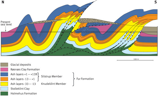
The principles of the glaciodynamic stratigraphy is exemplified by the Pleistocene drift deposits on Mors in Denmark, where the pre-Quaternary sedimentary rock units constitutes the Fur Formation, a Palaeogene succession of clayey diatomite with volcanic ash layers (Figure 3 and Figure 6). In the Quaternary stratigraphy dominated by till units representing Saalian unit as well as one or more Weichselian units the glacitectonite and the glaciotectonic unconformity helps to differentiate the various glaciodynamic stratigraphic groups Pedersen [1].
Figure 3.
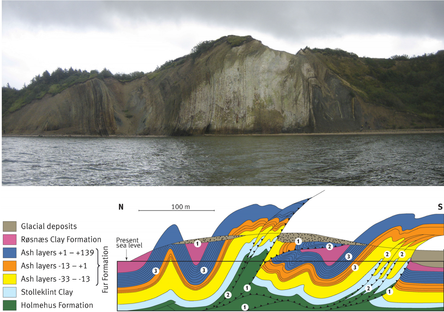
Coastal cliff exposure of the central part of a glaciotectonic complex. On the constructed geological cross section it is indicated that the décollement surface is located about 100 m below the sea level. At the sole of the thrust sheet to the north the hanging- wall side of the décollement surface is accurately exposed. The site is known as Fur Knudeklint (No. 3 in Figure 1), and the bedrocks comprise Paleocene/Eocene clayey units dominated by the diatomaceous Fur Formation containing 180 volcanic ash layers. Note that the photo only represents the northern half (left side) of the constructed cross section. Here an upright syncline is instructively outlined by the third-order surfaces, in this case ash layer bedding in the Fur Formation. The southern limb of the syncline comprises nearly the whole succession of the Fur Formation, which at the base passes into the Holmehus Formation. This formation comprises bentonite clay, a suitable lithology for sliding, in whichthe first- and second-order surfaces were developed. The shortening in this complex amounts to 43%, and the labeled numbers indicate the position of first-, second-, and third-order surfaces. Photo SASP 2012.
Figure 3.
Coastal cliff exposure of the central part of a glaciotectonic complex. On the constructed geological cross section it is indicated that the décollement surface is located about 100 m below the sea level. At the sole of the thrust sheet to the north the hanging- wall side of the décollement surface is accurately exposed. The site is known as Fur Knudeklint (No. 3 in Figure 1), and the bedrocks comprise Paleocene/Eocene clayey units dominated by the diatomaceous Fur Formation containing 180 volcanic ash layers. Note that the photo only represents the northern half (left side) of the constructed cross section. Here an upright syncline is instructively outlined by the third-order surfaces, in this case ash layer bedding in the Fur Formation. The southern limb of the syncline comprises nearly the whole succession of the Fur Formation, which at the base passes into the Holmehus Formation. This formation comprises bentonite clay, a suitable lithology for sliding, in whichthe first- and second-order surfaces were developed. The shortening in this complex amounts to 43%, and the labeled numbers indicate the position of first-, second-, and third-order surfaces. Photo SASP 2012.

Figure 4.
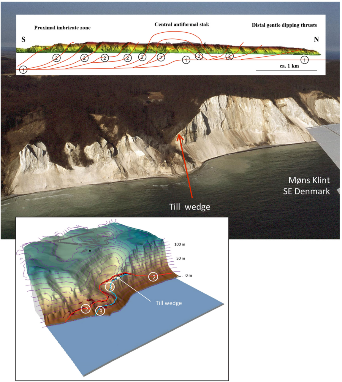
The construction of the décollement surface below Møns Klint (No. 7 in Figure 1) is based on balanced cross-section analysis of the photogrammetrically-based cross section of the cliff exposed above sea level. A back-stripping of the superimposed deformation affecting the northern part of the cliff [24] enables the construction of the combined thrust-fault framework for the deformation caused by the Baltic Ice Advance from the south (ca. 18,000 BP). The décollement surface is outlined by the circled label 1, and from this the thrust faults labeled 2 rise to the top of the complex. One of the keys for the interpretation of the structure is the till-wedge exposed on the southern part of Dronningestol displayed in the right half of the photo. The till-wedge was formed between the unconformity between the chalk and the till and the thrust fault at the base of the over-thrust chalk sheet. The till is a mixed diamictite related to the Swedish Ice Advance (ca. 24,000 BP), which was deposited prior to the thrusting. In the terrain model the unconformity is labeled 3 in the hierarchy of architectural surfaces, where it is grouped in the same order as bedding, and the thrust fault is labelled 2 according to the classification. The terrain model was constructed for assessment of chalk-cliff collapse at the Dronningestol [28]. The photo of the cliff section corresponds to the central antiformal-stack part of the glaciotectonic complex. Photo SASP 2003.
Figure 4.
The construction of the décollement surface below Møns Klint (No. 7 in Figure 1) is based on balanced cross-section analysis of the photogrammetrically-based cross section of the cliff exposed above sea level. A back-stripping of the superimposed deformation affecting the northern part of the cliff [24] enables the construction of the combined thrust-fault framework for the deformation caused by the Baltic Ice Advance from the south (ca. 18,000 BP). The décollement surface is outlined by the circled label 1, and from this the thrust faults labeled 2 rise to the top of the complex. One of the keys for the interpretation of the structure is the till-wedge exposed on the southern part of Dronningestol displayed in the right half of the photo. The till-wedge was formed between the unconformity between the chalk and the till and the thrust fault at the base of the over-thrust chalk sheet. The till is a mixed diamictite related to the Swedish Ice Advance (ca. 24,000 BP), which was deposited prior to the thrusting. In the terrain model the unconformity is labeled 3 in the hierarchy of architectural surfaces, where it is grouped in the same order as bedding, and the thrust fault is labelled 2 according to the classification. The terrain model was constructed for assessment of chalk-cliff collapse at the Dronningestol [28]. The photo of the cliff section corresponds to the central antiformal-stack part of the glaciotectonic complex. Photo SASP 2003.

Figure 5.
The majority of preserved glaciotectonic complexes from the Pleistocene were truncated by the advancing ice that created the complex. At the base of the translating ice, shear deformation created drag folds, which are superimposed by a cataclastic breccia—the glacitectonite. The photo illustrates a recent example of an advancing ice front over-riding a proglacial anticline crest-ridge and the formation of a glacitectonite at the base of the ice. Holm Lands Isbræ, NE Greenland, see Figure 2 for location. Photo SASP 1995.

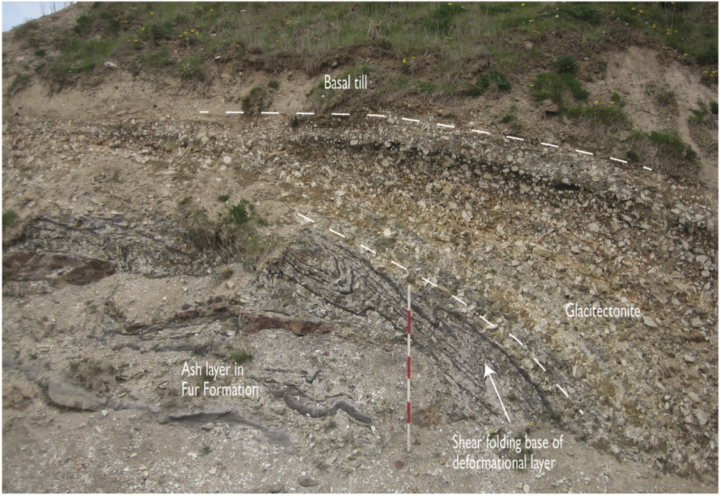
Figure 6.
Glacitectonite created on top of proglacially folded beds of volcanic ash layers in Eocene diatomite, the Fur Formation. During the ice advance, a lodgement till was typically deposited above the glacitectonite. Often a gradual transition occurs, and this alternating unit is referred to as the deformational layer, which comprises the second first order surface: the glaciotectonic unconformity. Photo SASP 2011.

4. The Second-Order Architectural Surfaces
The 2nd order surfaces are the thrust faults. These form the boundaries of the individual segments building up a complex. The geometry of ramps and flats can be interpreted from detachment folds, and duplexes may create complex repetitions of the geological successions. Two important types of surfaces are always distinguished: (1) the ramp which obliquely crosses the bedding, and (2) the flat which is a displacement surface parallel to bedding. The general dynamic in generating a system of thrust faults is that a succession of horizontal layers are pushed from the rear and that thrust faults are branching from the décollement surface displacing the hinterland part of the system up along a ramp towards the foreland (Figure 7). When one thrust sheet is resting on the back on another sheet it is referred to as piggy-back thrusting. The dynamic development predicts that the thrusting is sequential from the back towards the front of the glaciotectonic complex.
The thrust faults are the bounding surfaces of thrust sheets. The arrangement of the thrust faults, the second order surfaces in the glaciotectonic architecture, is best defined by four systems of thrust sheet features: (1) bedding parallel translated thrust sheets, (2) duplexes formation due to ramp collapse, (3) imbricate fans, and (4) stacked duplexes of thrust sheet segments.
Figure 7.
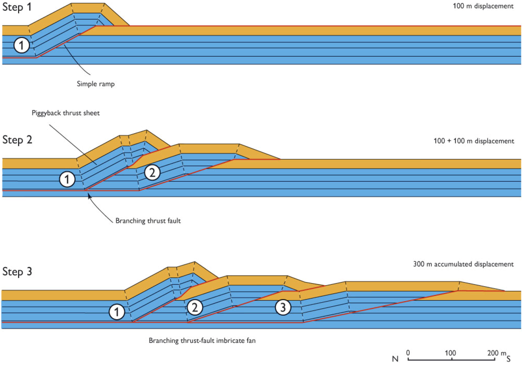
A computer-generated model demonstrating the formation of an imbricate fan by successive thrust-fault splays branching up from the main décollement surface. The encircled numbers refer to the sequential phase of thrust imbrication. Note that in the model the dip of the thrust faults decreases from the maximum angle of fracturing close to 45° and becoming more and more gently dipping towards the foreland.
Figure 7.
A computer-generated model demonstrating the formation of an imbricate fan by successive thrust-fault splays branching up from the main décollement surface. The encircled numbers refer to the sequential phase of thrust imbrication. Note that in the model the dip of the thrust faults decreases from the maximum angle of fracturing close to 45° and becoming more and more gently dipping towards the foreland.

4.1. The Translated Thrust Sheets
Towards the foreland the décollement surface steps up to a shallower level as indicated in Figure 4. In the foreland near fringe of the glaciotectonic complex the upper-most flat will form a displacement surface on top of the un-deformed foreland over which a thrust sheet is laterally displaced (Figure 8). The amount of displacement has been recognized to be in the order of 300–500 m of thrust sheets only about few tens of meters in thickness.
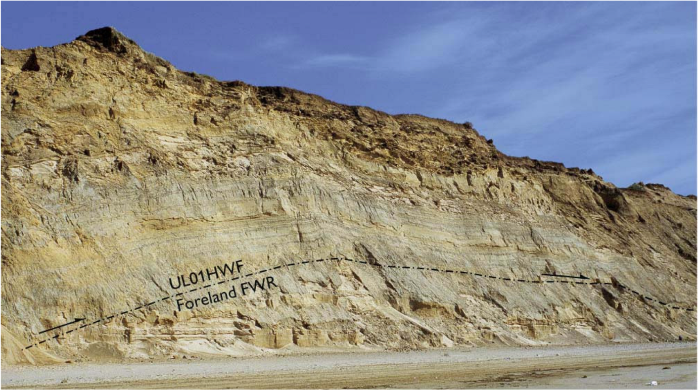
Figure 8.
An example of a thrust sheet translated on a flat on top of the surface of the foreland. Note the relatively gentle inclination of the ramp, which is a foot-wall ramp (FWR). The thrust sheet above is translated along the hanging-wall flat (HWF), and the identification of the thrust fault UL01 indicates that it is the distal-most thrust sheet in the glaciotectonic complex at Rubjerg Knude, northern Denmark (No. 2 in Figure 1) [4]. The lateral displacement amounts to 300 m over the undeformed foreland. The thrust sheet on the photo is only 15 m thick. Photo SASP 2002.

4.2. The Duplex Formation at Ramp Collapse
The computer model in Figure 7 demonstrates instructively the dynamics of ramp collapse. Successively a new thrust sheet is “broken off” from the foreland or the tailing end of a translated sheet. Complicated structural features can result from the ramp collapse dynamics, some of which will be described in the section below.
4.3. The Imbricate Fan
One of most characteristic features of glaciotectonic complexes is the imbricate fan (Figure 9). In the model for formation of imbricate fans in Figure 7 a dip of the thrust faults will not exceed 45°. However, in Figure 9 it is obvious that the angle is much steeper. The explanation for this is that a formerly formed ramp with a dip angle of about 30° is subsequently displaced along a later formed ramp with 30° resulting in an apparent dip of the early formed ramp of 60°. Hence it is demonstrated that very steep dips of ramps is the result for superimposed displacements along ramps (Figure 10).
The creation of at imbricate fan requires a décollement surfaces or a flat level along which the lateral displacement is taken place. A model for this is shown in Figure 10, which is an example from the Rubjerg Knude Glaciotectonic Complex in northern Denmark [4]. This imbricate fan demonstrates the creation of a stacking of steeply dipping thrust sheets due to the displacement along a flat level above the basal décollement surface. During the progressive deformation the succession between the intermediate flat level and the décollement surface was deformed and disrupted into a number of duplex segments that subsequently became stacked in an imbricate stacking feature.
Figure 9.
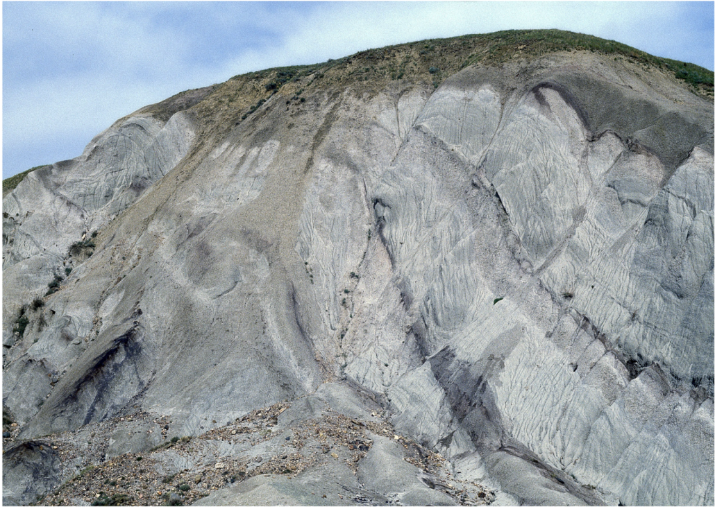
An example of steeply dipping thrust sheets in an imbricate fan of a glaciotectonic complex, the Mud Buttes in Alberta, Canada, which comprises Cretaceous sandstones displaced by the Wisconsian (Late Pleistocene) ice sheet advance [49]. The steeply dipping thrust-fault surfaces are interpreted as due to the piggy-back translation. Photo SASP 1993.
Figure 9.
An example of steeply dipping thrust sheets in an imbricate fan of a glaciotectonic complex, the Mud Buttes in Alberta, Canada, which comprises Cretaceous sandstones displaced by the Wisconsian (Late Pleistocene) ice sheet advance [49]. The steeply dipping thrust-fault surfaces are interpreted as due to the piggy-back translation. Photo SASP 1993.

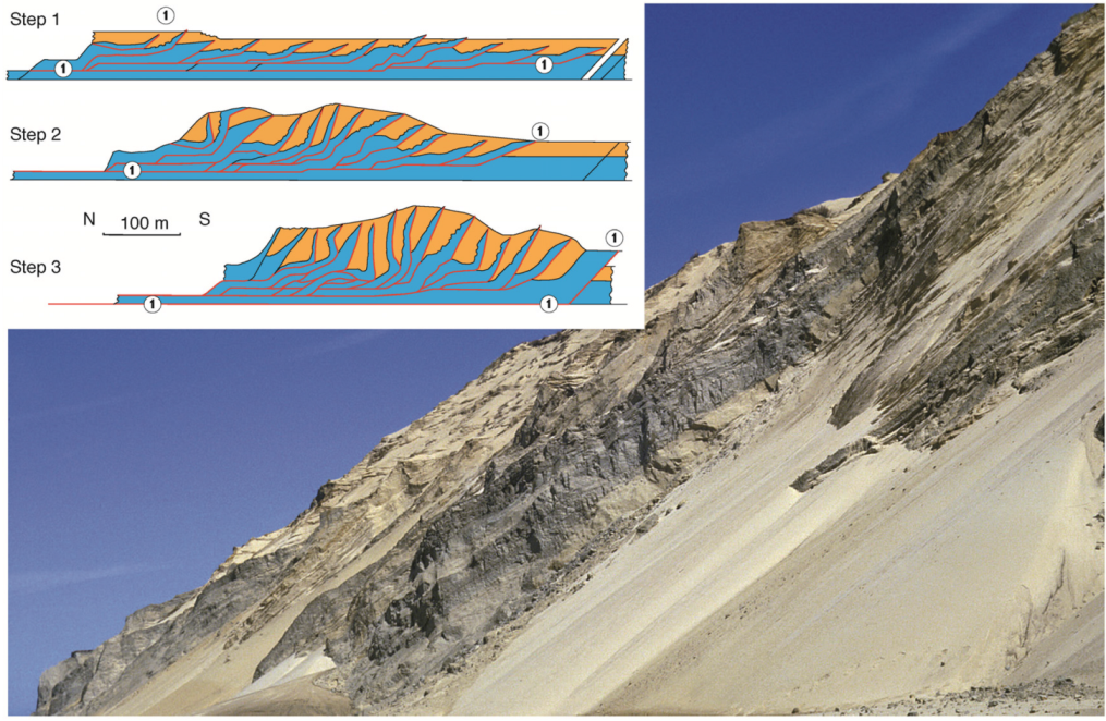
Figure 10.
A dynamic model for the piggyback thrusting in an imbricate fan demonstrates the steepening up of the thrust-fault surfaces. The example is taken from the central part of the Rubjerg Knude Glaciotectonic Complex, northern Denmark (No. 2 in FFigure 1). Step 1 is the initial thrusting, where the décollement level, labeled 1, follows a shallower flat-level. Step 2 illustrates the maximum stacking of thrust sheets during translation along the initial décollement surface. The displacement from Step 1 of 240 m increased to 500 m. In Step 3 the décollement level shifted to the final deep-seated position and the translation of the imbricate fan amounted to ca. 800 m. Due to the superimposed dislocation the thrust sheet reached their steeply dipping position. Note that label 1 in Step 1 indicates a syn-tectonical depositional top surface in the glaciofluvial Rubjerg Knude Formation (yellow in the diagram). The top surface of this formation represents the second first-order surface. The blue unit represents the clay-rich Lønstrup Klint Formation, and the décollement level is located at the transition from glaciomarine to glaciolacustrine deposition [50]. The photo illustrates the steeply dipping thrust sheets in the imbricate fan comprising 12 thrust-sheet segments. Photo SASP 2002.

4.4. The Stacked Duplexes of Thrust Sheet Segments
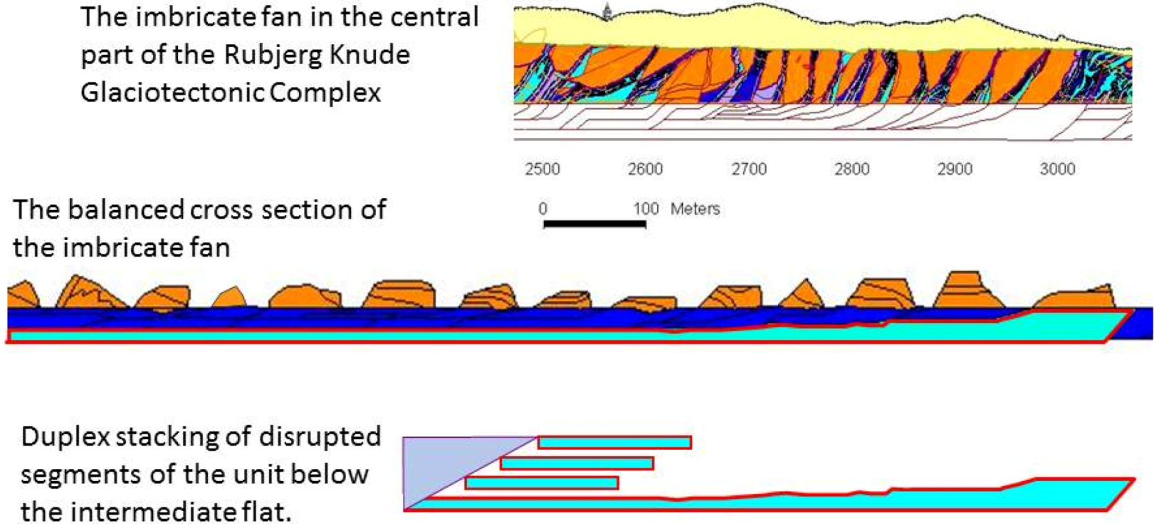
A very important tool for unraveling the structures in glaciotectonic complexes is the construction of balanced cross sections [51,52]. Based on this type of construction it is possible to predict the existence of duplex stacks. In Figure 11 the construction of the balanced cross section for the imbricate fan displayed in Figure 10 is presented. The model for the dynamic development in Figure 10 is naturally based on the construction of the balanced cross section. However, in Figure 11 the further development of the deformation of the lower unit between the flat level, which was the thrust fault for the imbricate fan translation, and the lower lying décollement surface is illustrated. Due to the balanced cross section is was evident that a long lower lying unit existed below the imbricate fan. At a later stage in the compressional deformation this unit was broken up into duplex segments, which were displaced on top of each other to form the duplex stack [4]. An example of how the duplex structures actual looks like is shown in Figure 12.
Figure 11.
Balanced cross-section of the central part of the Rubjerg Knude Glaciotectonic Complex, the imbricate fan occupying the section at the lighthouse. Note that the imbricate fan is truncated by a glaciotectonic unconformity on top of which recent dunes have been deposited (yellow unit). The orange color represents glaciofluvial sand deposited in piggyback basin between the clay-rich thrust sheets in bluish colors. The imbricate fan was formed during displacement along and intermediate flat level. At a later stage the unit between this flat and the lower lying décollement surface became compressed, and the unit broke up into segments that were displaced as duplexes on top of each other.

Figure 12.
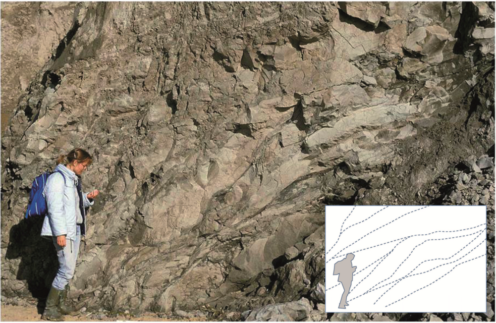
Stacked duplexes in the Rubjerg Knude Glaciotectonic Complex. The framework of the anastomosing thrust faults, which borders the duplex segments, is outlined by the dashed lines. Photo SASP1997.
Figure 12.
Stacked duplexes in the Rubjerg Knude Glaciotectonic Complex. The framework of the anastomosing thrust faults, which borders the duplex segments, is outlined by the dashed lines. Photo SASP1997.

5. The Third-Order Architectural Surfaces
Fold structures are regarded to represent the third-order of architectural surfaces. The compression of beds to create folds, like the anticline and syncline shown in Figure 13, will always require the existence of a décollement surface in the subsurface.
Figure 13.
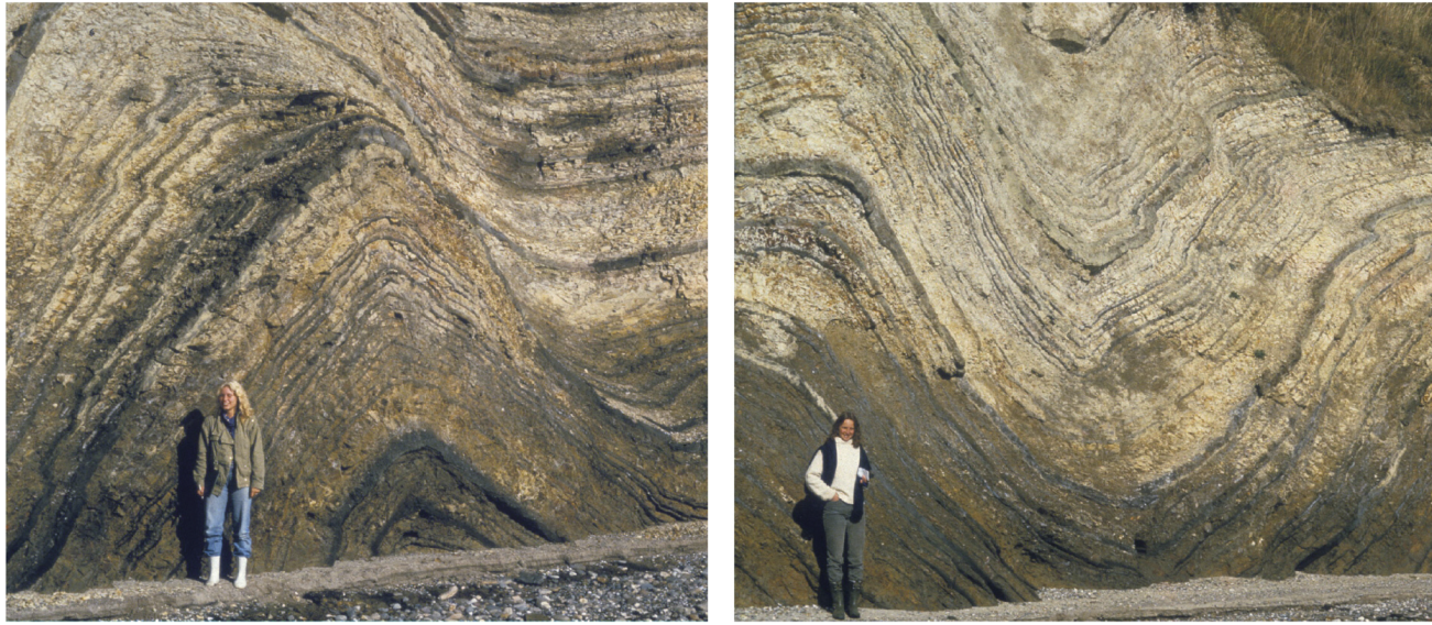
Parallel type of folding of volcanic ash layers in Eocene clayey diatomite in the Feggeklit Glaciotectonic Complex, northern Denmark. Note that on the left limb on the anticline (the left photo) and along the right limb of the syncline (right photo) the parasitic folds have a “wrong” vergency to the left. This is caused by sequential folding during the deformation. Photo SASP 1985.
Figure 13.
Parallel type of folding of volcanic ash layers in Eocene clayey diatomite in the Feggeklit Glaciotectonic Complex, northern Denmark. Note that on the left limb on the anticline (the left photo) and along the right limb of the syncline (right photo) the parasitic folds have a “wrong” vergency to the left. This is caused by sequential folding during the deformation. Photo SASP 1985.

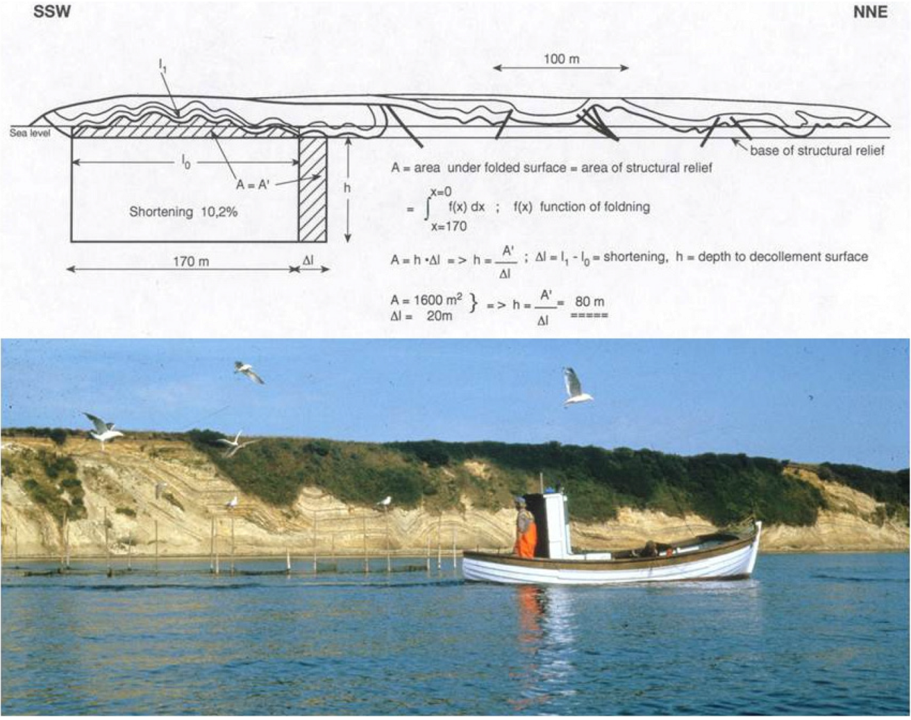
The anticlines in a carpet folded complex above a décollement surface may be regarded as pop up structures. These can be used for calculation of the depth to the décollement surface according to Suppe [52]. The construction of the depth to the décollement surface is demonstrated in Figure 14 for the structures in the Feggeklit glaciotectonic Complex.
The Hanging-Wall Anticlines
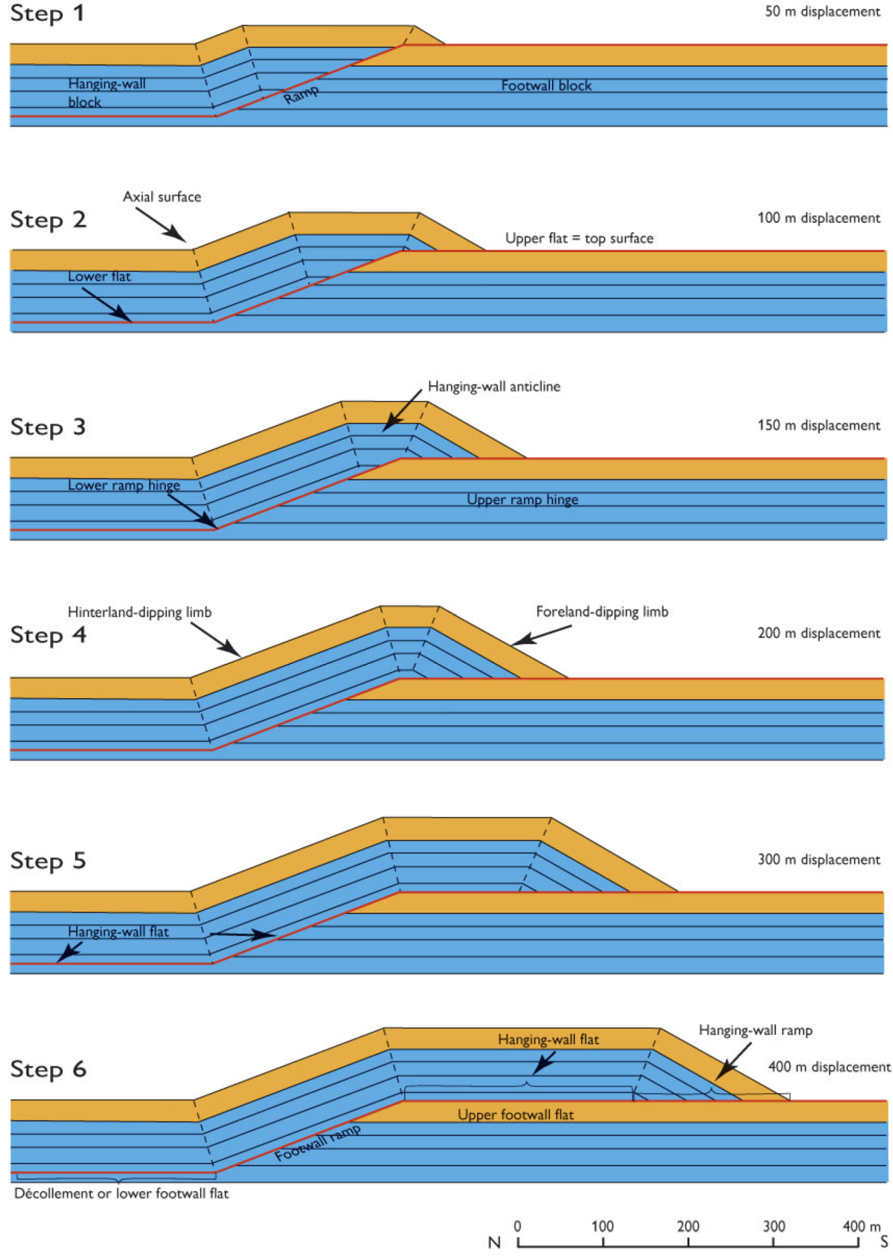
A special type of folds is particularly related the thrust-fault structures in the glaciotectonic complexes, namely the hanging-wall anticlines (Figure 15). These folds are formed at the frontal part of the thrust sheet due to the translation over the hinge between the ramp and upper-most flat. As demonstrated in the model in Figure 15 the shape of the anticline is directly related to the magnitude of displacement. A good example of the development of a hanging-wall anticline was presented by Klint and Pedersen [22], who constructed the dynamic development of the Hanklit glaciotectonic Complex, northern Denmark, based on a line balance of the exposed profile (Figure 16).
Figure 14.
The anticlines may be regarded as pop ups in the compressional deformation system and can help the construction of the depth to the décollement surface. The photo shows the glaciotectonic folded exposure at Feggeklit. The areal balance of the cross section demonstrates that a décollement surface is located at a depth of ca. 80 m below sea level. Construction from Pedersen [23]. Photo SASP 1985.

6. The Fourth-Order Architectural Surfaces
The fourth-order of surfaces comprise small scale structures, such as small-scale folds and faults—kink bands, conjugate faults, box folds, joints and anastomosing joints. These structures are important for the prediction of the details in the dynamic development as demonstrated by Pedersen [23]. One extraordinary example of these structures is selected for the demonstration of superimposed deformation during the development of structures in progressive glaciotectonic event. In the Feggeklit glaciotectonic Complex conjugate jointing and related box folds formed at an early stage of compressional deformation (Figure 17). At a later stage of deformation fold structures started to form thus displacing and deforming the early stage formed box folds. This demonstrates a high grade og lateral compression to be present throughout the deformation history.
Figure 15.
Computer-generated models of the development in the shape of hanging-wall anticlines depending on the magnitude of displacement. Note that an upright anticline is formed when the displacement is in the order of the thickness of the layer unit deformed. A frontal anticline similar to the one shown in Figure 16 requires a displacement, which is two times or more than the thickness of the deformed unit, compare with Steps 5 and 6.

Figure 16.
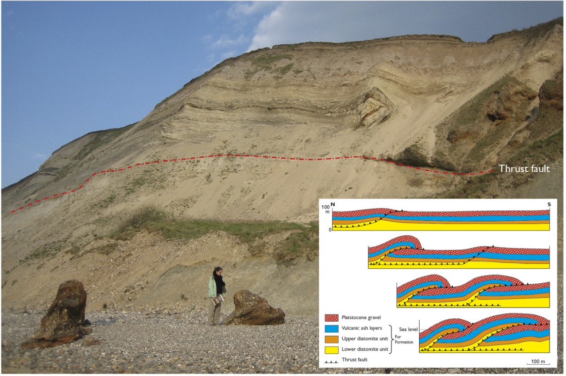
The Hanklit Glaciotectonic Complex, northern Denmark. The displacement of the Hanging-wall anticline is ca. 300 m, which is about 3 times the thickness of the thrust sheet. This type of flat-topped hanging-wall anticline compares to Step 6 in Figure 15. The inserted model for the progressive development of the thrust-fault deformation is after Klint and Pedersen [22]. Photo SASP 2009.
Figure 16.
The Hanklit Glaciotectonic Complex, northern Denmark. The displacement of the Hanging-wall anticline is ca. 300 m, which is about 3 times the thickness of the thrust sheet. This type of flat-topped hanging-wall anticline compares to Step 6 in Figure 15. The inserted model for the progressive development of the thrust-fault deformation is after Klint and Pedersen [22]. Photo SASP 2009.

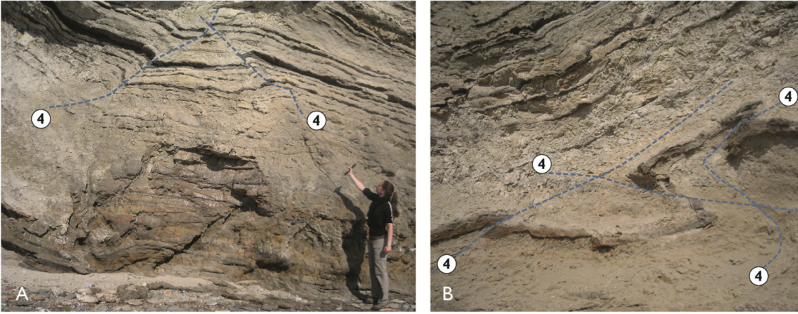
Figure 17.
The fourth-order of surfaces comprises small scale structures, which are important for the prediction of dynamic development. The box folds and related conjugate faults are good examples of this. (A) shows a nearly intact box fold developed in the Feggeklit Glaciotectonic Complex. The joint/kinkband-lines are labelled 4. The perpendicular direction to the zone axis of the conjugate faults indicates the direction of ice push. (B) shows the same type of structure, but here it is distorted an displaced at the limb of a larger anticline, an instructive example of superimposed deformation during the development within a glaciotectonic event. Photo SASP 2009.

7. Discussions
The discussions of the concept of the architecture of glaciotectonic complexes address four questions of importance for structural and glacial geologists. The first question is: Will the concept help us in mapping out glaciotectonic complexes? Which means areas/volumes/places, where the subsurface has a more complex framework than just the ordinary horizontal bedding. The second question is: Can the concept be applied to solve any problems in structural or engineering geology? The third question concerns how we can differentiate between architecture and structure in general including muddiapirism, superimposed folding and superposed deposition or/and erosion. Finally, the last question concerns the proglacial versus replicative push during retreat and the concept of glaciotectonic architecture surfaces.
7.1. Mapping Glaciotectonic Complexes
The system of architecture is suggested for specifying that there are fields, which despite their chaotic nature can be mapped and treated systematically. For each glaciotectonic complex an ordering is possible. In the geological mapping the glaciotectonic complexes can be identified and their location presented. One example of this is presented in a newly published map from Denmark (Figure 18) [53]. In this map a number of glaciotectonic complexes have been recognized, and their geomorphological features, which is their second first-order surface, have been presented by hill-shade graphic presentation. The boundaries between the fronts of the complexes and their forelands have been mapped out and are presented as the tip-lines of the first first-order surfaces.
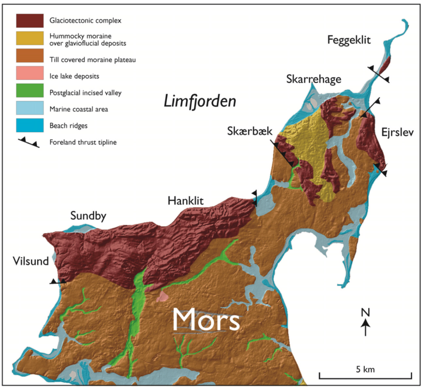
The glaciotectonic complexes mapped out in the northern part of the island Mors (Figure 18) clearly indicates two directions of ice-push. The Hanklit and Sundby complex demonstrates an ice-push direction from the north. This reflects the Norwegian Ice Advance about 27,000 years BP, and the glaciotectonic complexes Skærbæk and Ejerslev have a dominating trend NW–SE indicating an ice push from the Swedish Ice Advance about 24,000 [4,53]. The Skarrehage complex is characterized by superimposed folding by both glaciodynamic events [24]. The mapping of the complexes has supported the areal limitation of raw material interests and the assessment of preservation planning.
7.2. Application of Glaciotectonic Architecture
Structural geologists are familiar with solving problems related to tectonic complexes. They have no problems with using a wide range of terms describing structures from macro- to micro-scale, they can handle the problems related to orientations of elements in a 3D framework, and they can manage tools for statistic speculative analysis of structural complexity. However, for a large range of geoscientists and engineers structural geology is a complex field difficult to get insight in. It is the intension that the simple ordering of the architectural elements can make an elegant tool for coping with problems of structural geology. A demonstration of this is given by the case from a raw material investigation in the glaciotectonic complex at Ejerslev on Mors in Denmark (Figure 19 and Figure 20).
For the planning of future raw material exploitation in the Ejerslev diatomaceous-clay pit it was important to know two factors: (1) the variation in thickness of overburden, and (2) the location and the amount of good quality clay. For solving these problems a number of boreholes were drilled (Figure 19), and it was expected that a simple model could be constructed for the calculation of the two factors. However, in a glaciotectonic complex it is wishful thinking to expect simple models. Fortunately a maker bed, one of the 180 ash layers in the Fur Formation, was identified, which served as fixed third-order surfaces (Figure 20). By Kriging of the position of the marker third-order surface in the boreholes the amount of overburden could be calculated, and the decision of drawing the cut-off boundary could be made for the future planning of the excavation. The question concerning the amount of raw material was solved partly by the use of the contouring of the third-order surface (Figure 19) and partly by a speculative analysis of the depth of the second- and first-order surfaces. Meanwhile the depth of excavation was also depending on the level of the groundwater, which to some extend depended on the second-order surfaces, but was managed in another branch of geosciences.
Figure 18.
The glaciotectonic complexes mapped out on the island of Mors (location No. 3 in Figure 1). The hilly landscapes on northern Mors are characterised by a number of glaciotectonic complexes. The mapping of these is based on geomorphological analysis, which is here visualized by the hill-shading terrain model. The boundaries of the complexes and their forelands are mapped by tracing the frontal tip-lines of the first first-order surfaces. The hinterland of the complexes constitutes the glaciotectonic depressions, the holes in the hill–and–hole pairs, now occupied by Limfjorden sea waters. From Pedersen and Jakobsen [53].

7.3. Limits of the Application of the Glaciotectonic Architecture Concept
In general it could be argued that there is no need for an architecture classification and ordering for glaciotectonics. All the elements incorporated can be described by terms and concepts of structural geology. One argument defending the use of the architecture system was given above, and another argument is that the use of the term architecture should clarify the application. When a title on a paper includes the term architecture, people should be aware of the elements included. Architecture describes surfaces and their relations to create constructions. However, in geology we know a number of features that are not surface specific, or which by deformation became so chaotic that a simple architectural description is not possible. Diapirs and complexes resulting from poly-diapirism [4] is one of them, and superimposed interference patterns are additionally a type of features, which are best managed with descriptions, interpretations and analyses using “hard core” structural geology. In a number of glaciotectonic complexes we have to deal with problems of superimposed deformation and interference of proglacial folding, brecciation and shearing, often overprinted by soft sedimentary mud-mobilization [24,35]. Again it is emphasized that such problems needs not to be covered by the concept of architectural ordering, but are much better treated by the tools of structural geology.
Figure 19.
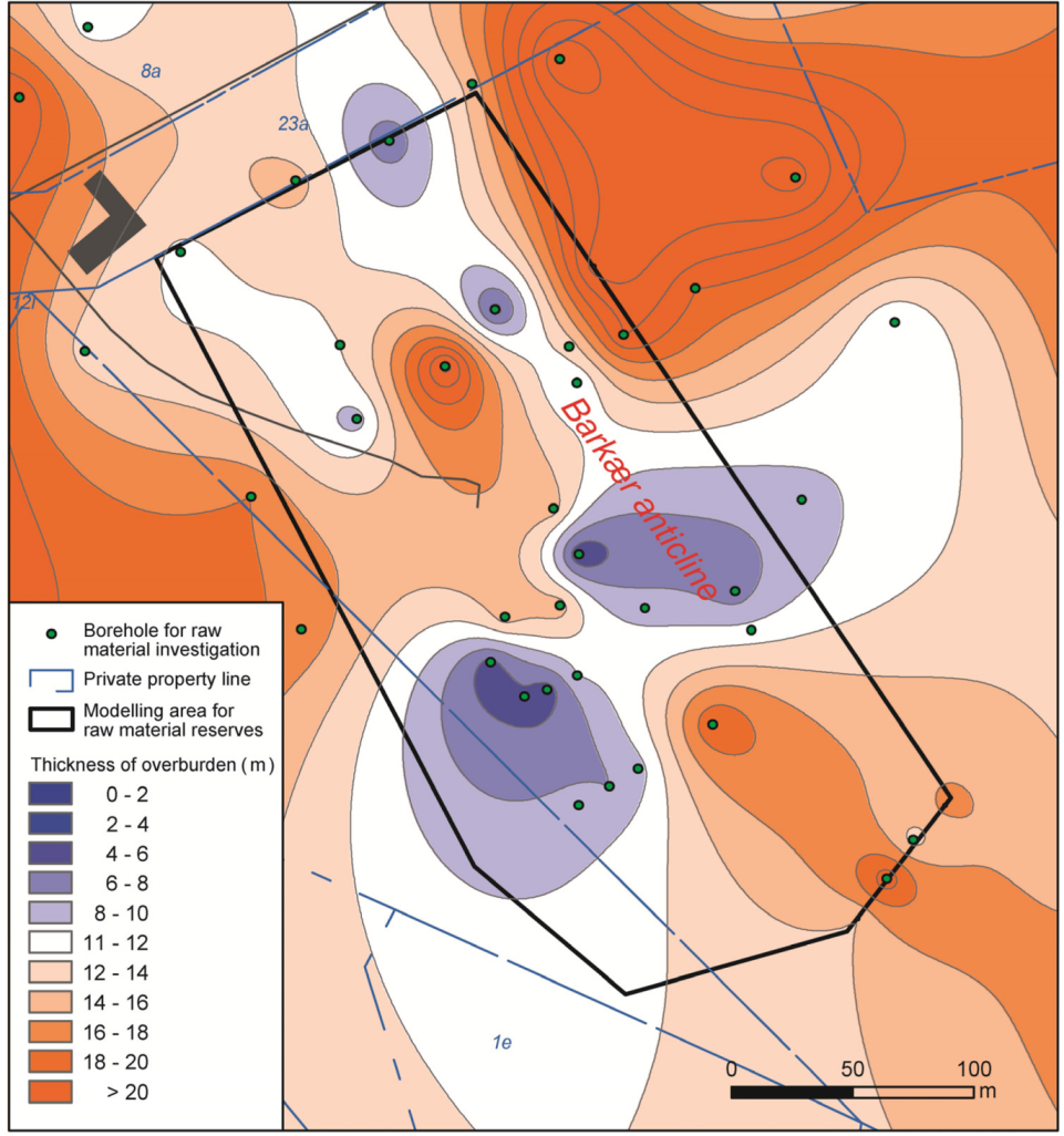
A structural contour map of third-order surface applied in a raw material planning case in a glaciotectonic complex, the Barkær case, Ejerslev, Mors, Denmark (see Figure 18 for location of Ejerslev). The contour lines indicate the depth from the terrain surface to the third-order marker surface, which is illustrated in Figure 20. The shallow depth to the raw material is illustrated by blue intervals, which in the map outline a NW-trending crest of an anticline, the Barkær anticline. An additional anticline is recognized SW of the Barkær anticline, and due to scarcity of boreholes, decision of excavation relied on the structural geological interpretation. From Pedersen [54] and a number of confidential technical reports.
Figure 19.
A structural contour map of third-order surface applied in a raw material planning case in a glaciotectonic complex, the Barkær case, Ejerslev, Mors, Denmark (see Figure 18 for location of Ejerslev). The contour lines indicate the depth from the terrain surface to the third-order marker surface, which is illustrated in Figure 20. The shallow depth to the raw material is illustrated by blue intervals, which in the map outline a NW-trending crest of an anticline, the Barkær anticline. An additional anticline is recognized SW of the Barkær anticline, and due to scarcity of boreholes, decision of excavation relied on the structural geological interpretation. From Pedersen [54] and a number of confidential technical reports.

Figure 20.
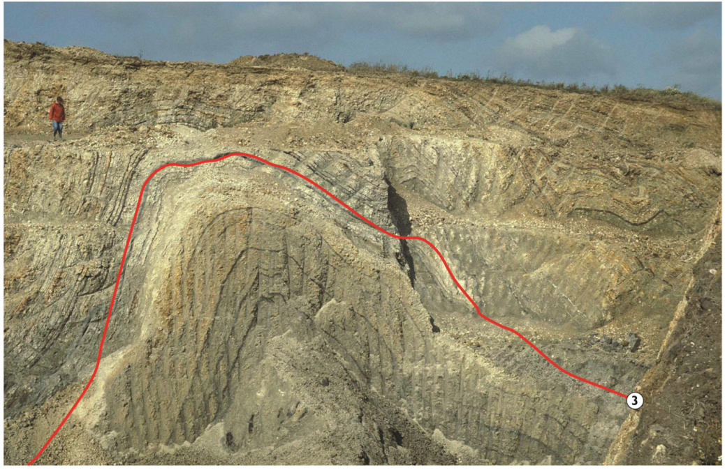
A cross section of the Barkær anticline exposed in a pre-existing wall in the clay pit at Ejerslev, Mors, Denmark. The location of Ejerslev is shown in Figure 18, and the location of the Barkær anticline is illustrated in Figure 19. The red line outlines the position of the marker third-order surfaces (labelled with 3), represented by the top of the ash layer +19 in a series of 180 ash layers in the Fur Formation. Above the third-order marker surface the density of ash layers is too high for utilizing the diatomaceous clay, wherefore it is classified as overburden together with the basal till, which discordantly truncates the proglacially folded beds. Photo SASP 1989.
Figure 20.
A cross section of the Barkær anticline exposed in a pre-existing wall in the clay pit at Ejerslev, Mors, Denmark. The location of Ejerslev is shown in Figure 18, and the location of the Barkær anticline is illustrated in Figure 19. The red line outlines the position of the marker third-order surfaces (labelled with 3), represented by the top of the ash layer +19 in a series of 180 ash layers in the Fur Formation. Above the third-order marker surface the density of ash layers is too high for utilizing the diatomaceous clay, wherefore it is classified as overburden together with the basal till, which discordantly truncates the proglacially folded beds. Photo SASP 1989.

7.4. Proglacial versus Replicative Push during Retreat
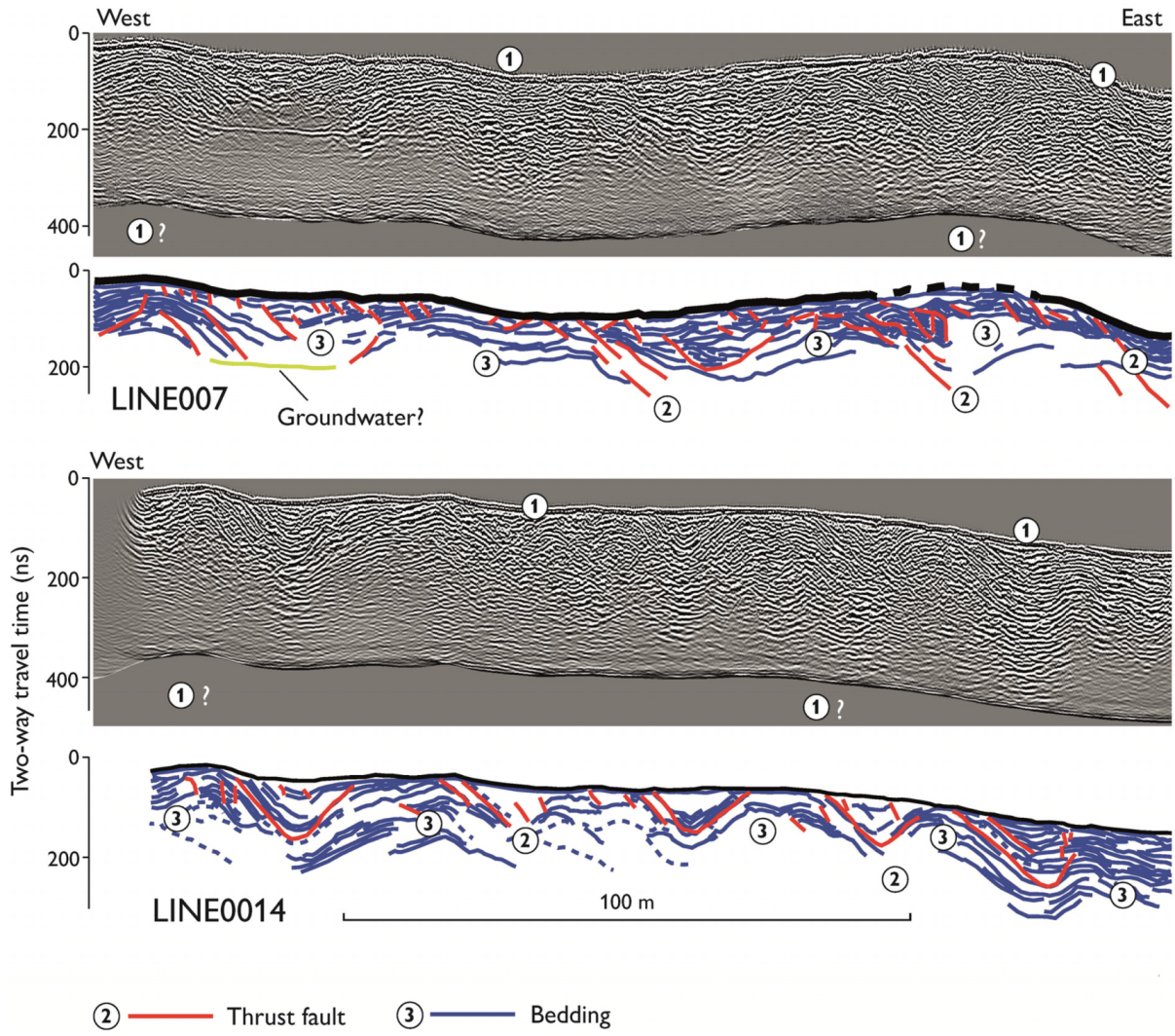
The reason for bringing this question up is that the concept of architecture for glaciotectonic complexes was originally formulated on the back ground of large glaciotectonic complexes comprising uniform organization of first-order surfaces: a décollement surface at the base and a glaciotectonic unconformity at the top. However, glaciotectonic complexes formed during readvances of a retreating ice margin do occur. An example of this was recently investigated during systematic mapping of Quaternary deposits in Himmerland, NE Denmark [55]. During the mapping it was realized that the forest-covered landscape comprised ribbed moraines formed during the retreat of the Scandinavian ice about 20,000–19,000 years BP [56,57]). For the documentation of the internal structures in the moraine ridges a detailed investigation with ground-penetrating radar (GPR) was carried out (Figure 21). This documented the internal architectures of third-order elements, whereas the second-order elements had to be interpreted from the discontinuities dividing the third-order surfaces. The second first-order surface constitutes the top of the third-order surfaces and the erosional terrain surface, which were never overridden by the ice after the fault-bend folding of the ice-marginal deposits. The first first-order surface was not predictable in the geo-radar (GPR) profiles. However, from drill holes and exposures in a nearby located gravel pit, the top of a basal till is interpreted to be situated just below the reflections of the third-order surfaces (marked with label 1 and question mark in Figure 21).
Figure 21.
Two geo-radar (GPR) profiles from ribbed moraines in Himmerland, NE Denmark, demonstrate an example of the application of glaciotectonic architecture in a complex formed during readvances of a retreating ice margin. In the interpreted sections below the geo-radar profiles the second-order and third-order surfaces has been drawn up (labeled 2 and 3). The eroded terrain surface represents one of the first-order surfaces, whereas the other first-order surface, the décollement level (labeled 1 with question mark), is situated just below the recorded reflectors. This surface is located on top of a basal till deposited prior to the recession of the ice, and probably the clay content in the till hampered the signal to be reflected. The scale in the profile is almost one to one, where 20 ns equal 1 m. From Lerche et al. [56].

The example of the ribbed moraine ridges in Himmerland demonstrates the same first-order surface relationship as recent glaciotectonic complexes, and that such ridges can been described with the use of the suggested order of architectural surfaces. However, it should be noted that the size of proglacial glaciotectonic complexes is four times the magnitude of glaciotectonic complexes formed by readvances during recession of the ice margin. This difference in size reflects that the power of an advancing ice is much greater than the power in the ice mass, where the main accumulation in the source area has stopped.
8. Conclusions
A classification of glaciotectonic architecture is suggested, and four orders of surfaces are defined for the description of glaciotectonic complexes:
First-order surfaces are the décollement surface and the top of the complex, which can be a glaciotectonic unconformity, the recent terrain surface or succeeding deposits covering an erosional unconformity.
Second-order surfaces are ramps and flats—the thrust faults, which frames the individual segments in the glaciotectonic complex.
Third-order surfaces are folded beds—anticlines and synclines. Internal unconformities and boundaries between different geological units are additionally included in this order.
Fourth-order surfaces are small scale folds and faults—kink bands, conjugate faults, box folds, etc.
The systematics of architecture is demonstrated for a wide range of glaciotectonic complexes. The application of the suggested ordering of architectural surfaces is presented. Often the term architecture is used without clear references to its meaning, which in this presentation has been addressed for improvement of the description of glaciotectonic complexes. It is regarded important to apply architecture for elements of surfaces, and that surfaces comprise constructions. In geology tectonic complexes equal the constructions build by the first to fourth order surfaces.
Acknowledgments
The author would like to thank three anonymous referees for their criticism, which contributed to improvements of the paper. Moreover, Professor Ken McCaffrey, guest editor of this special issue on Earth architecture, is thanked for advises and supporting comments for concluding this contribution. Benny Shark (Graphic Section, GEUS) helped with drafting the figures, which is greatly appreciated. Thomas Vangkilde-Pedersen (Head of department of Groundwater and Quaternary Geology Mapping, GEUS) is thanked for the support of the glaciotectonic studies. This paper is published with permission of the Geological Survey of Denmark and Greenland (GEUS 2014).
Conflicts of Interest
The author declares no conflict of interest.
References
- Pedersen, S.A.S. Glaciodynamic sequence stratigraphy. In Glaciogenic Reservoirs and Hydrocarbon Systems; Special Publications Volume 368; Huuse, M., Redfern, J., Le Heron, D.P., Dixon, R.J., Moscariello, A., Craig, J., Eds.; Geological Society of London: London, UK, 2012; pp. 29–51. [Google Scholar]
- Andersen, L.T. The Fanø Bugt Glaciotectonic Thrust Fault Complex, Southeastern Danish North Sea: A Study of Large-Scale Glaciotectonics Using High-Resolution Seismic Data and Numerical Modelling. PhD Thesis, Geological Survey of Denmark and Greenland (GEUS), Copenhagen, Denmark, 2004. [Google Scholar]
- Huuse, M.; Lykke-Andersen, H. Large-scale glaciotectonic thrust structures in the eastern Danish North Sea. In Deformation of Glacial Materials; Special Publications; Malbman, A., Hambrey, M., Hubbard, B., Eds.; Geological Society of London: London, UK, 2000; Volume 176, pp. 293–305. [Google Scholar]
- Pedersen, S.A.S. Structural analysis of the Rubjerg Knude Glaciotectonic Complex, Vendsyssel, northern Denmark. Geol. Surv. Den. Greenl. Bull. 2005, 8, 1–192. [Google Scholar]
- Aber, J.S.; Croot, D.; Fenton, M.M. Glaciotectonic Landforms and Structures; Glaciology and Quaternary Geology Series Volume 5; Kluwer Academic Publishers: Dordrecht, The Netherlands, 1989. [Google Scholar]
- Aber, J.S.; Ber, A. Glaciotectonism; Development in Quaternary Sciences Volume 5; Elsevier: Amsterdam, The Netherlands, 2007. [Google Scholar]
- Brookfield, M.E. The origin of bounding surfaces in aeolian sandstones. Sedimentology 1977, 24, 303–332. [Google Scholar]
- Allen, J.R.L. Studies in fluviatile sedimentation: Bars, bar-complexes and sandstone sheets (low-sinuosity braided streams) in the Brownstones (L. Devonian), Welsh Borders. Sediment. Geol. 1983, 33, 237–293. [Google Scholar]
- Miall, A.D. Architectural-element analysis: A new method of facies analysis applied to fluvial deposits. Earth Sci. Rev. 1985, 22, 261–308. [Google Scholar]
- Miall, A.D. Architectural elements and bounding surfaces in fluvial deposits: Anatomy of the Kayenta Formation (Lower Jurassic), southwest Colorado. Sediment. Geol. 1988, 55, 233–262. [Google Scholar]
- Best, J.L.; Ashworth, P.J.; Bristow, C.S.; Roden, J. Three-dimensional sedimentary architecture of a large, mid-channel sand braid bar, Jamuna River, Bangladesh. J. Sediment. Res. 2003, 73, 516–530. [Google Scholar]
- Dam, G. Sedimentology of magmatically and structurally controlled outburst valleys along rifted volcanic margins: Examples from the Nuussuaq Basin, West Greenland. Sedimentology 2002, 49, 505–532. [Google Scholar]
- Andersen, T.R.; Huuse, M.; Jørgensen, F.; Christensen, S. Seismic investigations of buried tunnel valleys on- and offshore Denmark. In Glaciogenic Reservoirs and Hydrocarbon Systems; Huuse, M., Redfern, J., Le Heron, D.P., Dixon, R.J., Moscariello, A., Craig, J., Eds.; Special Publications; Geological Society of London: London, UK, 2012; Volume 368, pp. 129–144. [Google Scholar]
- Kolla, V.; Posamentier, H.W.; Wood, L.J. Deep-water and fluvial sinuous channels—Characteristics, similarities and dissimilarities, and modes of formation. Marin. Pet. Geol. 2007, 24, 388–405. [Google Scholar]
- Kristensen, T.B.; Huuse, M. Multistage erosion and infill of buried Pleistocene tunnel valleys and associated seismic velocity effects. In Glaciogenic Reservoirs and Hydrocarbon Systems; Special Publications Volume 368; Huuse, M., Redfern, J., Le Heron, D.P., Dixon, R.J., Moscariello, A., Craig, J., Eds.; Geological Society of London: London, UK, 2012; pp. 159–172. [Google Scholar]
- Jørgensen, F.; Sandersen, P.B.E.; Auken, E. Imaging buried Quaternary valleys using the transient electromagnetic method. J. Appl. Geophys. 2003, 53, 199–213. [Google Scholar]
- Jørgensen, F.; Sandersen, P.B.E.; Auken, E.; Lykke-Andersen, H.; Sørensen, K. Contributions to the geological mapping of Mors, Denmark—A study based on a large-scale TEM survey. Bull. Geol. Soc. Den. 2005, 52, 53–75. [Google Scholar]
- Sandersen, P.B.E.; Jørgensen, F. Buried Quaternary Valleys in western Denmark—Occurrence and inferred implications for groundwater resources and vulnerability. J. Appl. Geophys. 2003, 53, 229–248. [Google Scholar]
- Svendsen, J.I.; Alexanderson, H.; Stakhov, V.I.; Demidov, I.; Dowdeswell, J.A.; Funder, S.; Gaataullin, V.; Henriksen, M.; Hjort, C.; Houmark-Nielsen, M.; et al. Late Quaternary ice sheet history of northern Eurasia. Quat. Sci. Rev. 2004, 23, 1229–1271. [Google Scholar] [Green Version]
- Rafaelsen, B.; Andreassen, K.; Hogstad, K.; Kuilman, L.W. Large-scale glaciotectonic imbricated thrust sheets on three-dimensional seismic data: Facts or artefacts? Basin Res. 2007, 19, 87–103. [Google Scholar]
- Gry, H. De istektoniske Forhold i Moleret. Med bemærkninger om vore dislocerede klinters dannelse og om den negative askeserie. Meddelelser fra Dansk Geologisk Forening 1940, 9, 586–627. (In Danish) [Google Scholar]
- Klint, K.E.S.; Pedersen, S.A.S. The Hanklit glaciotectonic thrust fault complex, Mors, Denmark; DGU Serie A Volume 35; Geological Survey of Denmark: Copenhagen, Denmark, 1995. [Google Scholar]
- Pedersen, S.A.S. Progressive glaciotectonic deformation in Weichselian and Palaeogene deposits at Feggeklit, northern Denmark. Bull. Geol. Soc. Den. 1996, 42, 153–174. [Google Scholar]
- Pedersen, S.A.S. Superimposed deformation in glaciotectonics. Bull. Geol. Soc. Den. 2000, 46, 125–144. [Google Scholar]
- Pedersen, S.A.S.; Petersen, K.S.; Rasmussen, L.A. Observations on glaciodynamic structures at the Main Stationary Line in western Jutland, Denmark. In Glaciotectonic Forms and Processes; Croot, D.G., Ed.; A.A. Balkema: Rotterdam, The Netherlands, 1988; pp. 177–183. [Google Scholar]
- Pedersen, S.A.S.; Petersen, K.S. Djurslands Geologi; Geological Survey of Denmark and Greenland: Copenhagen, Denmark, 1997. (In Danish) [Google Scholar]
- Madsen, T.M.; Piotrowski, J.A. Genesis of the glaciotectonic thrust-fault complex at Halk Hoved, southern Denmark. Bull. Geol. Soc. Den. 2012, 60, 61–80. [Google Scholar]
- Pedersen, S.A.S.; Gravesen, P. Structural development of Maglevandsfald: A key to understanding the glaciotectonic architecture of Møns Klint, SE Denmark. Geol. Surv. Den. Greenl. Bull. 2009, 17, 29–32. [Google Scholar]
- Gribb, K. Jasmund und Moen eine glacialmorphologische Untersuchung. Zeithschrift für Erdkunde 1947, 1, 75–182. (In German) [Google Scholar]
- Ludwig, A.O. Zwei markante Stauchmoränen: Peski/Belorussland und Jasmund, Ostseeinsel Rügen/Nordostdeutschland—Gemeinsame Merkmale und Unterschiede. Eisezeitalter und Gegenwart Quaternary Science Journal 2011, 60, 464–487. (In German) [Google Scholar]
- Steinich, G. Endogene tektonik in den Unter-Maastricht-Vorkommen auf Jasmund (Rügen). Geologie 1972, 71–72, 1–207. (In German) [Google Scholar]
- Warren, W. Field Guide for Excursion; For INQUA Commission on Formation and Properties of Glacial Deposits. Dublin, Ireland, May 1991. [Google Scholar]
- Brandes, C.; Le Heron, D.P. The glaciotectonic deformation of Quaternary sediments by fault-propagation folding. Proc. Geol. Assoc. 2010, 121, 270–280. [Google Scholar]
- Thomas, G.P. The origin of the glacio-dynamic structures of the Bride Moraine, Isle of Man. Boreas 1984, 13, 355–364. [Google Scholar]
- Burke, H.; Phillips, E.; Lee, J.R.; Wilkinson, I.P. Imbricate thrust stack model for the formation of glaciotectonic rafts: An example from the Middle Pleistocene of north Norfolk, UK. Boreas 2009, 13, 620–637. [Google Scholar]
- Hart, J.K. Proglacial glaciotectonic deformation and the origin of the Cromer Ridge push moraine complex, North Norfolk, England. Boreas 1990, 19, 165–180. [Google Scholar]
- Hart, J.K.; Boulton, G.S. The glacial drifts of northeastern Norfolk. In Glacial Deposits in Great Britain and Ireland; Ehlers, J., Gibbard, P.L., Rose, J., Eds.; A.A. Balkema: Rotterdam, The Netherlands, 1991; pp. 233–243. [Google Scholar]
- Kupetz, M. Geologischer Bau und Genese der Stauchmoräne Muskauer Faltenbogen. Brandenburgische Geowissenschaften und Rohstoffe 1997, 2, 1–20. (In German) [Google Scholar]
- Kupetz, A.; Kupetz, M.; Rascher, J. Der muskauer Faltenbogen—Ein geologisches Phänomen, Grundlage einer 130 jährigen standortgebundenen Wirtschaftsentwwicklung und Geopark in Brandenburg, Sachsen under Wojewodschaft Lubuser Land; Gesellschaft für Geowissenschaften e.V.: Berlin, Germany, 2004. (In German) [Google Scholar]
- Włodarski, W. Geometry and kinematics of glaciotectonic deformation superimposed on the Cenozoic fault-tectonic framework in the central Polish Lowlands. Quat. Sci. Rev. 2014, 94, 44–61. [Google Scholar]
- Molodkov, A.; Bitinas, A.; Damusyte, A. IR-OSL studies of till and inter-till deposits from the Lithuanian Maritime Region. Quat. Geochronol. 2010, 5, 263–268. [Google Scholar]
- Croot, D.G. Morphological, structural and mechanical analysis of neoglacial ice-pushed ridges in Iceland. In Glaciotectonics Forms and Processes; Croot, D.G., Ed.; A.A. Balkema: Rotterdam, The Netherlands, 1988; pp. 33–47. [Google Scholar]
- Boulton, G.S.; van der Meer, J.J.M.; Beets, K.J.; Hart, J.K.; Ruegg, G.H.J. The sedimentary and structural evolution of a recent push moraine complex: Holmströmbreen, Spitsbergen. Quat. Sci. Rev. 1999, 18, 339–371. [Google Scholar]
- Pedersen, S.A.S. Isfoldede lag i de danske kystklinter. In Geologiske Naturperler—Danske Brikker til Jorden Puslespil; Lindow, B., Krüger, J., Eds.; Gyldendal: Copenhagen, Denmark, 2011; pp. 113–127. (In German) [Google Scholar]
- Boulton, G.S.; Caban, P. Groundwater flow beneath ice sheets: Part II—Its impact on glacier tectonic structures and moraine formation. Quat. Sci. Rev. 1995, 14, 563–587. [Google Scholar]
- Banham, P.H. Glacitectonites in till stratigraphy. Boreas 1977, 6, 101–105. [Google Scholar]
- Pedersen, S.A.S. Glacitectonite: Brecciated sediments and cataclastic sedimentary rocks formed subglacially. In Genetic Classification of Glacigenic Deposits; Goldthwait, R.P., Matsch, C.L., Eds.; A.A. Balkema: Rotterdam, The Netherlands, 1988; pp. 89–91. [Google Scholar]
- Boulton, G.S.; Hindmarsh, R.C.A. Sediment deformation beneath glaciers: Rheology and geological consequences. J. Geophys. Res. 1987, 92, 9059–9082. [Google Scholar]
- Fenton, M.; Langenberg, W.; Pawlowicz, J. Glacial Deformation Phenomena of East-Central Alberta in the Stettler-Coronation Region; Field Trip Guidebook; Geological Association of Canada: St. John’s, Canada, 1993. [Google Scholar]
- Sadoline, M.; Pedersen, G.K.; Pedersen, S.A.S. Lacustrine sedimentation and tectonics: An example from the Weichselian at Lønstrup Klint, Denmark. Boreas 1997, 26, 113–126. [Google Scholar]
- Fossen, H. Structural Geology; Cambridge University Press: Cambridge, UK, 2010. [Google Scholar]
- Suppe, J. Principles of Structural Geology; Prentice-Hall, Inc.: Englewood Cliffs, NJ, USA, 1985. [Google Scholar]
- Pedersen, S.A.S.; Jakobsen, P.R. Geological Map of Denmark: Mors; Geological Survey of Denmark and Greenland: Copenhagen, Denmark, 2012; Map Sheet, 1:50000. [Google Scholar]
- Pedersen, S.A.S. Palaeogene diatomite deposits in Denmark: Geological investigations and applied aspects. Geol. Surv. Den. Greenl. Bull. 2008, 15, 21–24. [Google Scholar]
- Jakobsen, P.R.; Nielsen, A.M.; Pedersen, S.A.S. Geological Map of Denmark: Mariager; Geological Survey of Denmark and Greenland: Copenhagen, Denmark, 2013; Map Sheet, 1:50000. [Google Scholar]
- Lerche, H.; Jakobsen, P.R.; Pedersen, S.A.S. Ribbed moraines formed during the retreat of the Scandinavian ice sheet from eastern Himmerland, NE Jylland, Denmark. Geol. Surv. Den. Greenl. Bull. 2014, 31, 39–42. [Google Scholar]
- Sandersen, P.B.E.; Jørgensen, F.; Larsen, N.K.; Westergaard, J.H.; Auken, E. Rapid tunnel-valley formation beneath the receding Late Weichselian ice sheet in Vendsyssel, Denmark. Boreas 2009, 28, 834–851. [Google Scholar]
© 2014 by the author; licensee MDPI, Basel, Switzerland. This article is an open access article distributed under the terms and conditions of the Creative Commons Attribution license (http://creativecommons.org/licenses/by/4.0/).
Share and Cite
MDPI and ACS Style
Pedersen, S.A.S. Architecture of Glaciotectonic Complexes. Geosciences 2014, 4, 269-296. https://0-doi-org.brum.beds.ac.uk/10.3390/geosciences4040269
AMA Style
Pedersen SAS. Architecture of Glaciotectonic Complexes. Geosciences. 2014; 4(4):269-296. https://0-doi-org.brum.beds.ac.uk/10.3390/geosciences4040269
Chicago/Turabian StylePedersen, Stig A. Schack. 2014. "Architecture of Glaciotectonic Complexes" Geosciences 4, no. 4: 269-296. https://0-doi-org.brum.beds.ac.uk/10.3390/geosciences4040269