Article

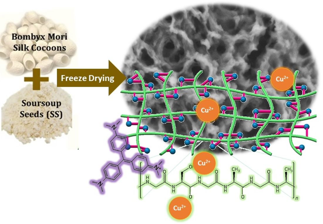
Hierarchically 3-D Porous Structure of Silk Fibroin-Based Biocomposite Adsorbent for Water Pollutant Removal

1
Department of Chemical Engineering, Institut Teknologi Kalimantan, Balikpapan 76127, Indonesia
2
Department of Engineering Physics, Institut Teknologi Sepuluh Nopember, Surabaya 60111, Indonesia
3
Department of Chemical Engineering, Universitas Internasional Semen Indonesia, Gresik 61122, Indonesia
4
Department of Chemical and Bioengineering Technology, University of Kuala Lumpur, Lot 1988 Kawasan Peindustrian Bandar Vendor, Taboh Naning, Alor Gajah 78000, Malaysia
5
Department of Chemical Engineering, Institut Teknologi Sepuluh Nopember, Surabaya 60111, Indonesia
6
Research Center for Chemistry, Indonesian Institute of Sciences, Kawasan PUSPIPTEK Serpong, Tangerang Selatan 15314, Indonesia
7
Faculty of Life and Environmental Sciences, University of Tsukuba, Tannodai 1-1, Tsukuba 305-8577, Japan
*
Authors to whom correspondence should be addressed.
Submission received: 21 October 2021 / Revised: 11 November 2021 / Accepted: 12 November 2021 / Published: 16 November 2021

Abstract

:
This study explored the tunability of a 3-D porous network in a freeze-dried silk fibroin/soursop seed (SF:SS) polymer composite bioadsorbent. Morphological, physical, electronic, and thermal properties were assessed using scanning electron microscopy, the BET N2 adsorption-desorption test, Fourier transform infrared (FTIR) spectroscopy, and thermogravimetric analysis (TGA). A control mechanism of pore opening–closing by tuning the SS fraction in SF:SS composite was found. The porous formation is apparently due to the amount of phytic acid as a natural cross-linker in SS. The result reveals that a large pore radius is formed using only 20% wt of SS in the composite, i.e., SF:SS (4:1), and the fibrous network closes the pore when the SS fraction increases up to 50%, i.e., SF:SS (1:1). The SF:SS (4:1) with the best physical and thermal properties shows an average pore diameter of 39.19 nm, specific surface area of 19.47 m2·g−1, and thermal stability up to ~450 °C. The removal of the organic molecule and the heavy metal was assessed using crystal violet (CV) dye and the Cu2+ adsorption test, respectively. The adsorption isotherm of both CV and Cu2+ on SF:SS (4:1) follows the Freundlich model, and the adsorption kinetic of CV follows the pseudo-first-order model. The adsorption test indicates that physisorption dominates the adsorption of either CV or Cu2+ on the SF:SS composites.

Graphical Abstract

1. Introduction

There are equally large numbers of heavy metals, dyes, organic solvents, gasoline oil, salts, hydrocarbons, and other toxic chemical substances associated with industrial waste. These contaminants have significant potential to either directly or indirectly pollute surface water. Contamination of surface water may lead to low drinking water quality, loss of water supply, downgraded surface water systems, high clean-up costs, high costs for alternative water supplies, and potential health problems. Among various available wastewater treatments, adsorption is considered the most promising method to remove dyes and heavy metals [1]. Over the years, activated carbon has been the most utilized adsorbent throughout the world. However, activated carbon suffers from several drawbacks, including high cost, complex separation process, and difficulty of regeneration, which restrict its usefulness in water treatment [2]. In recent years, increasing attention has been paid to the development of alternative adsorbents that can overcome the drawbacks of activated carbon. In this regard, adsorbents from natural resources have gained significant interest because of their facile preparation, high availability, eco-friendly characteristic, and low cost [3]. Numerous renewable materials from agricultural products and by-products have been used as adsorbents for dyes and heavy metals removal from aqueous media by many researchers [3,4,5]. In the past few decades, researchers have used the agricultural wastes such as linen [6], walnut shell [7], mustard cake [8], rice straw [9], and a combination of rice husk, ground nutshell, and soya beans waste [10] as adsorbents for heavy metals and dyes removal from aqueous solution. However, most of the reported bioadsorbents exhibited the limitation of adsorption capacity and slow adsorption rate. Hence, exploring highly efficient bioadsorbents for environmental treatment is still demanded.
Another versatile bioadsorbent material is silk fibroin (SF), which is one of the abundant biopolymers that has provoked numerous investigations due to its nontoxicity, biodegradable, and biocompatible characteristics [11,12,13]. Silk fibroin contains amine, a hydroxyl and ketone group that can be utilized as an active side to attract and bind broader types of heavy metals and dyes compared to cellulose-based agricultural waste. This structure promotes itself as a potential bioadsorbent for dye and heavy metal in wastewater treatment.
Many works related to porous SF scaffolds have been reported in the past decade: These porous 3-D structures have been prepared by various preparation routes, such as reinforcing [14,15], electro-spinning [16], solvent casting [15,17], freeze-drying [18,19], salt-leaching [20,21], or gas foaming [22]. As previously reported, a freeze-dried porous 3-D structure has been successfully prepared in the presence of an appropriate cross-linker [23]. It was also reported that a repeating freeze-drying process is considered an effective method to form a porous blended fibroin-poly(vinyl alcohol) [24]. However, most of the abovementioned studies involve potentially hazardous chemicals, require cross-linking chemicals which are not environmentally friendly. Furthermore, it is also difficult to prepare patterned SF scaffolds due to the instability of the proteins under the harsh treatment conditions [25,26,27]. In addition, the application of the 3-D porous SF scaffolds has been intensively explored for the development of biomedical materials [28,29], especially in the tissue engineering field, but is lacking for the development of wastewater treatment technology.
With regard to its potential for wastewater treatment materials, the performance of SF can be significantly increased by chemical modification or compositing. For instance, SF/polyethyleneimine (PEI) hydrogel shows high adsorption capacity for the removal of various heavy metals, including Zn2+, Ni2+, Cu2+, Cd3+, Pb2+, and Ag+ ion [11]. For a layer-by-layer structure of SF/PEI, the resultant materials demonstrate moderate adsorption capacity of Cu2+ ions [30]. Another SF modification using 3,5-bis-{2-hydroxyphenyl-5-[(2-sulphate-4-sulphatoethylsulphonyl-azobenzol) methylene amino]} benzoic acid demonstrates low adsorption capacity of Cd3+ [31]. Inorganic modification shows relatively high adsorption capacity, whereas organic materials-modified SF still shows low performance. Compositing SF with biomaterials, e.g., wool, has been reported to have low adsorption capacity even though the initial concentration of feed is low [32]. This low adsorption capacity may be due to the low porosity and pore volume of the adsorbent. For an efficient adsorbent, higher porosity is desirable because a higher surface area facilitates higher adsorption capacity of the dyes and heavy metals. Nonetheless, high hydrophilicity of SF leads to a complicated fabrication process, and a highly porous structure is difficult to obtain because the generated fibroin easily collapses.
In this contribution, we present an alternative synthetic route of SF-based adsorbent extracted from silkworm cocoons, which were composited with another biomaterials, i.e., soursop seeds (SS) powder. The synthesis was undertaken via a freeze-drying method which required no repeating freeze–thaw treatment and hazardous chemicals. The natural cross-linking agents from SS play a role in controlling the porosity of SF:SS composites. The influences of adsorption parameters, such as the contact time, the adsorbent composition, and the initial concentration of dye and heavy metal ions, on the adsorption performance of SF:SS were evaluated in detail. In this paper, the adsorption kinetics of organic dyes and the adsorption isotherms of heavy metal ions are also described. To the best of our knowledge, there is no study reported in literature that combined SS powders with a solid matrix of SF for water remediation applications, and specifically for the removal of heavy metal ions and dye contaminants. The exploration of this SF:SS composite material may open the doorway to further applied research.

2. Materials and Methods

2.1. Materials

Soursop seed from the local plantation was washed and purified with 0.2 M hydrochloric acid solution (HCl, Sigma-Aldrich, Steinheim, Germany) for 24 h. Silkworm cocoons (Bombyx mori) were purchased from CV Nurra Gemilang (Malang, East Java, Indonesia), used, and kept in a desiccator overnight to avoid adsorption of water molecules from the air. Sodium carbonate anhydrous (Na2CO3, MERCK, Darmstadt, Germany) and calcium chloride dihydrate (CaCl2·2H2O, 94% MERCK, Singapore) were used as chemical reagents. Ethanol absolute, a cellulose-based dialysis tube (MW Cut-off: 12.000–14.000), and distilled water were used as received. Crystal violet (CV) purchased from CV Nurra Gemilang (Malang, East Java, Indonesia) and Copper (II) sulfate pentahydrate (CuSO4·5H2O, MERCK, Darmstadt, Germany) were used as dye substances and as heavy metal pollutant, respectively.

2.2. Preparation of Regenerated Silk Fibroin Solution

The silkworm cocoons were cut and cleaned using 0.5% Na2CO3 solution in the boiling distilled water for 30 min. Afterwards, the materials were rinsed with the same amount of solvent and volume at 40–50 °C for 30 min. The obtained sample was pure silk fibroin in the fiber form after drying using an air-dryer and placing in a desiccator overnight to yield the degummed silk. The degummed silk (1/20, w/v) was dissolved in a mixed solvent (CaCl2·2H2O/water/EtOH, 1/6/2 in mole ratio) and stirred at 70–80 °C for 2 h to form a clear solution. The regenerated silk fibroin was then dialyzed using 500 mL deionized water for two days to remove salt and ethanol from the reagent. Dialysis was carried out using a dialyses cassette (80 mL maximum capacity) to avoid an increasing volume of regenerated silk fibroin. The dialysis solvent was replaced every 30 min in the first 2 h and then replaced at 12 h intervals for 3 days.

2.3. Preparation of SF:SS Composite Adsorbent Using Freeze Drying

The preparation of composite was carried out by mixing the pristine SF and soursop seeds powder after the dialysis process. For fabrication of SF:SS scaffolds in the freeze-drying method (BUCHI L300, Jakarta, Indonesia), the solutions containing 10 w/v% of SF:SS composites with various mass ratios were thoroughly frozen below −20 °C in a sterile, 15 mL glass bottle, and then evacuated in a lyophilizer (Lyo-vapor L-300) over 12 h to induce ice sublimation. Finally, it yielded the freeze-dried powder of composite SF:SS.

2.4. Organic Dye and Heavy Metal Adsorption Test

Various SF:SS composites were investigated as adsorbent for crystal violet (CV) and Cu2+ (CuSO4·5H2O, MERCK 99%, Darmstadt, Germany) removal from aqueous solution. Batch adsorption experiments were conducted in a 50 mL flask with 150 mg dried SF:SS composites. The initial concentrations of both CV and Cu2+ were 10–50 mg·L−1. After adsorption at a desired condition (sampling time of 10, 20, 30, 40, 60, 90, and 120 min at room temperature), the solution was separated from the adsorbent. The remaining CV concentration was measured at maximum absorbance 670 nm using a UV/vis spectrometer (Rayleigh UV-9200, Beijing, China), and the Cu2+ concentration was quantified using an atomic absorption spectrometer (Perkin Elmer Analyst, Santa Clara, CA, USA). In addition, the effects of pH on the adsorption of Cu2+ metal ions at initial concentrations of 20 mg·L−1 were investigated. The pH of the solution was adjusted in the range of 1–10 using 0.1 M HCl and 0.1 M NaOH. The spectroscopic data of either CV and Cu2+ (see Figures S3 and S4 in the Supplementary Materials) was then used for quantitative analysis for kinetics and adsorption isotherm studies. The temporal adsorption capacity (qt in mg·g−1) of CV and Cu2+ was determined as follows:
q t = ( C 0 C t ) V m
where C0 and Ct are the initial and final concentration of either CV or Cu2+ solution (mg·L−1), respectively, V is the volume of solution (L), and m is the weight of adsorbent (g). The adsorption kinetic of CV was evaluated using pseudo-first and second order kinetic model as follows [33,34]:
ln ( C e C t ) = ln ( C e ) k 1 t
and:
t q t = 1 k 2 q e 2 + t q e
where Ce and Ct are concentration of CV at equilibrium and the time t, respectively, qe and qt (mg·g−1) is the amount of dye adsorbed at equilibrium and the time t (min), respectively, k1 and k2 (min−1) and are the pseudo-first order and pseudo-second-order rate constants, respectively.
The adsorption isotherm of both CV and Cu2+ was assessed using the Langmuir and Freundlich isotherm models [35,36]. The Langmuir isotherm model is expressed as follows:
C e q e = 1 q m a x k L + C e q m a x
where kL represents the Langmuir adsorption constant, Ce is the equilibrium concentration of either CV or Cu2+ (mg·L−1), qe is the amount of CV or Cu2+ adsorbed at equilibrium, and qmax represents the maximum adsorbed amount of the composite SF/SS (mg·g−1). For the Freundlich isotherm, the mathematical model is expressed as follows:
ln ( q e ) = k F + 1 n ln ( C e )
where kF is Freundlich isotherm constant, 1/n is the influence coefficient of solution concentration to the equilibrium adsorption capacity, where n < 1 indicates chemisorption and n > 1 indicates physisorption.

2.5. Characterizations

Scanning electron microscopy (SEM, HITACHI SU-3500, Tokyo, Japan) operated at 10 kV accelerating voltage was employed to assess micromorphology of SF:SS composites. Fourier transform infrared (FTIR) spectra of the resultant SF and SF:SS composites were recorded in a mixed KBr pellet using a Spectrum BX (Perkin Elmer, Rodgau, Germany) spectrometer, ranging from 400 to 4000 cm−1. Thermogravimetric analyses (TGA) of SF and SF:SS were carried out on a thermogravimeter (Pyris-1 TGA, Perkin Elmer, Shelton, CT, USA) from room temperature to 800 °C with a heating rate of 10 °C min−1 in N2 at a flow rate of 10 mL·min−1. Brunauer–Emmett–Teller (BET) N2 adsorption/desorption isotherms were measured at 77 K (Quantachrome, NOVA 4200E, Odlezhausen, Germany). Prior to BET testing, the sample was dried at 200 °C in N2 for 3 h.

3. Results and Discussions

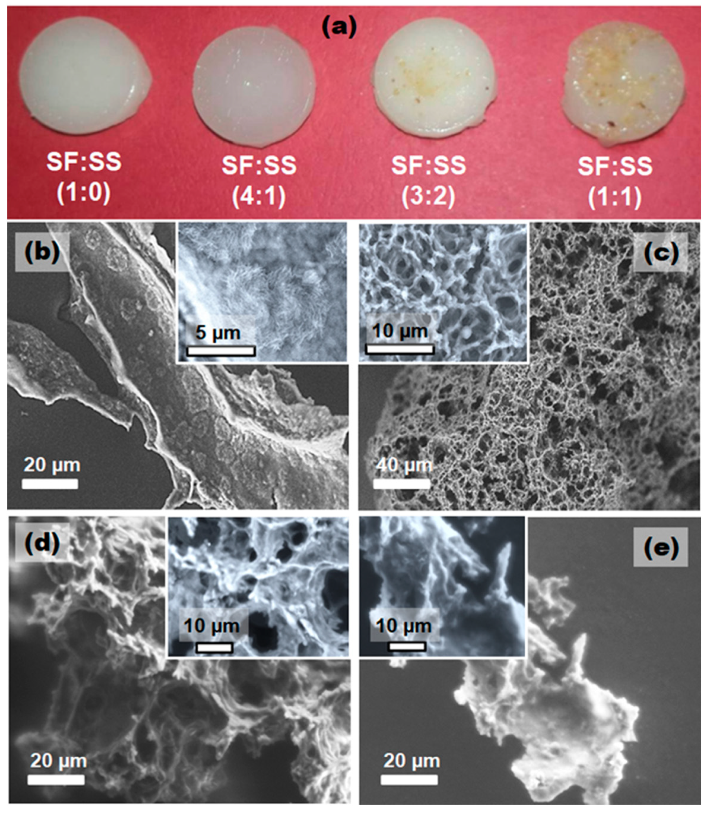
3.1. Micromorphology of SF:SS Composite Adsorbent

The resultant SF:SS hydrogel prior freeze drying is shown in Figure 1a. It is visible that both SF:SS (4:1) and (1:1) show a semi-transparent structure whereas the pristine SF and SF:SS (3:2) reveal an opaque surface. These qualitative optical properties of the hydrogel indicate that the voids within both SF:SS (4:1) and (1:1) structures occupy quite a larger volume than those in the pristine SF and SF:SS (3:2). This further indicates that the pore volume should be higher in both SF:SS (4:1) and (3:2). Upon freeze drying, the resulting SF:SS composite powders can be seen in Figure S1 (in the Supplementary Materials) and the respective micromorphology is depicted in Figure 1b–e.
As shown, the pristine SF is marked by a fractal structure (Figure 1b). The surface of this fractal SF exhibits very dense unstructured nanofibrils (inset Figure 1b), indicating that the contraction of SF is not dominant during the freeze-drying process. Such dense nanofibrils were also reported in the literature [37], in which silk fibroin in CaCl2 solution preserved its dense fibrous structure. Compositing the pure SF with SS significantly alters the architecture of the porous network (Figure 1c,d). It is likely that the addition of 20–40% of SS in the composite enables the pore-opening process to occur during freeze drying. Both SF:SS (4:1) and SF:SS (3:2) reveal a 3-D interconnected fibrous structures with smaller and larger pore diameter, respectively. Surprisingly, increasing SS content in SF:SS (1:1) results in a dense fibrous arrangement. Thus, 50% of SS matrix closes the gap between SF fibers, leading to coalesced nanofibrils in the fractal structure. It is worth noting that the pore structure and volume in this SF:SS composite play a critical role in controlling the diffusion of targeted molecules or adsorbate [38]. In addition, the pore opening and closing mechanism in SF:SS composite structure is somewhat controlled by the ratio of SS within the composite.

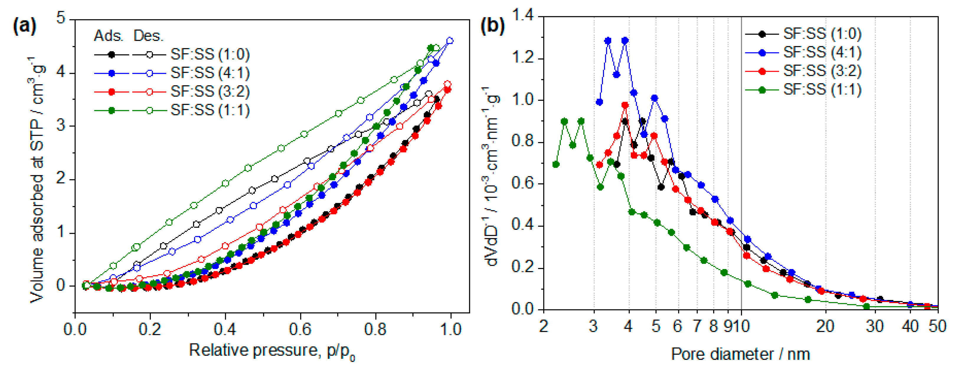
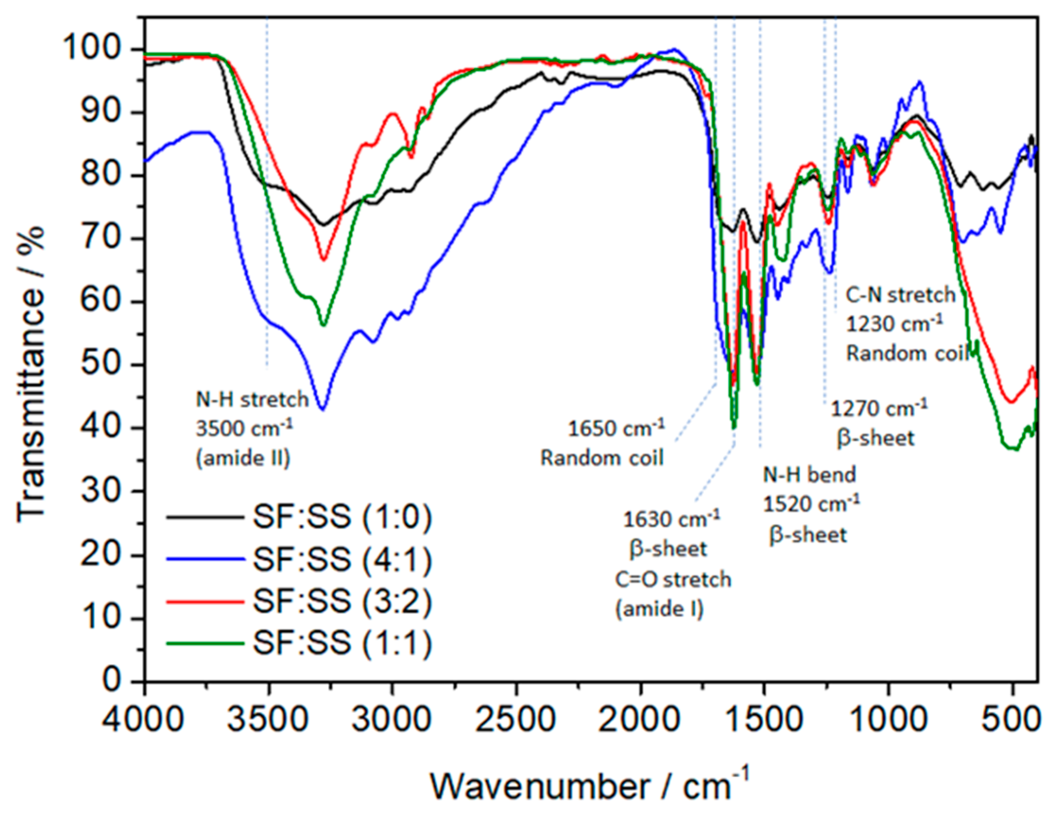
3.2. Physical Properties of SF:SS Composite Adsorbent

To gain further insight into the physical properties of SF:SS composites, BET (Brunauer–Emmett–Teller) measurements were carried out yielding the N2 adsorption-desorption isotherm and the pore size distribution (Figure 2), and the resulting physical properties are summarized in Table 1. In general, the open-loop adsorption isotherm is attributed to the chemisorption of N2 where the vacant sites are not the same as the occupied sites. Furthermore, the hysteresis may arise from the occurrence of irreversible capillary condensation within the defined mesoporous structure. The isotherm of SF:SS composites can be assigned to a type III isotherm, corresponding to non-porous or microporous materials. Moreover, the hysteresis loops of H3 according to IUPAC classification indicate the presence of slit-like pores.
Quantitative analysis reveals that the SF:SS (4:1) shows the highest surface area, which was on par with that of the SF:SS (3:2), i.e., 19.5 vs. 17.2 m2·g−1. Both composites have a specific surface area that is up to four-fold higher than that obtained for SF:SS (1:0) and SF:SS (1:1). This very large surface area, especially for SF:SS (4:1), is in agreement with the SEM observation, which is manifested from the high porosity of the structure. This composition shows the highest average pore diameter and pore volume of 39.2 nm and 0.00811 cc·g−1, respectively. Although SF:SS (4:1) and SF:SS (3:2) are at the “open-mode” of the fibrous structure, the “close-mode” observed in SF:SS (1:0) and SF:SS (1:1) shows an average pore diameter of one order of magnitude smaller than that in SF:SS (4:1) and SF:SS (3:2), i.e., 2.2–3.7 nm.

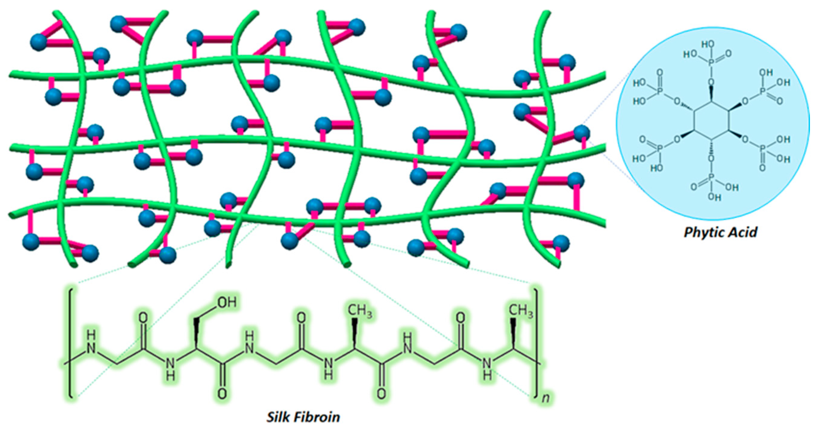
3.3. Proposed Pore Formation in SF:SS Composite Adsorbent

As we indicated previously that the opening–closing mechanism of the fibrous structure is affected by the SS composition, the pore formation mechanism will be interesting for future manipulation strategies developed during the synthesis and preparation of SF:SS. Here, the proposed formation mechanism is further assessed based on the FTIR spectra of pristine SF (or SF:SS(1:0)) and various SF:SS composites (Figure 3). The FT-IR spectrum of SF:SS (1:0) exhibits absorption peaks at 3423 and 3174 cm−1 due to -NH stretching of the secondary amide; C-H stretching at 2922 and 2850 cm−1; C=O stretching at 1643 cm−1; -NH bending at 1545 cm−1; and -NH out-of-plane at 700 cm−1. The absorption peak at 1625 cm−1 (amide I); 1525 cm−1 (amide II), and 1265 cm−1 (amide III) can be assigned to the lineaments for the silk II structural conformation (β-sheet). The adsorption bands at 1520 cm−1 (amide II) and 1226 cm−1 (amide III) are attributed to the silk I conformation [39,40].
Upon increasing SS content in the composite, the IR absorption peaks at 3423, 3174, and 1545 cm−1 decrease. This decreasing signal of -NH is likely due to the bond formation between the sericin fraction of SF and the phytic acid contained in SS [41], which can also act as a natural cross-linker within the composites [42,43]. The phytic acid possessed six phosphate linking groups that can bind with amide groups in the SF backbone. Despite the non-prominent signal observed, the free phosphate radical of phytic acid is indicated by the IR absorption at ~1100 cm−1. In this work, optimum physical properties of SF:SS were obtained for the concentration of phytic acid in the 20% SS mass fraction. The result reflects that a higher cross-linker does not necessarily lead to a better pore structure. The sufficient amount of phytic acid cross-linker in 20–40% SS assists in the opening of dense SF nanofibrils. A higher concentration of phytic acid cross-linker, i.e., >50%, causes the porous fiber of SF to coalesce and, hence, leads to the closing mechanism of the pore network of SF:SS composites. The structure of the resultant SF:SS composites is illustrated in Figure 4.

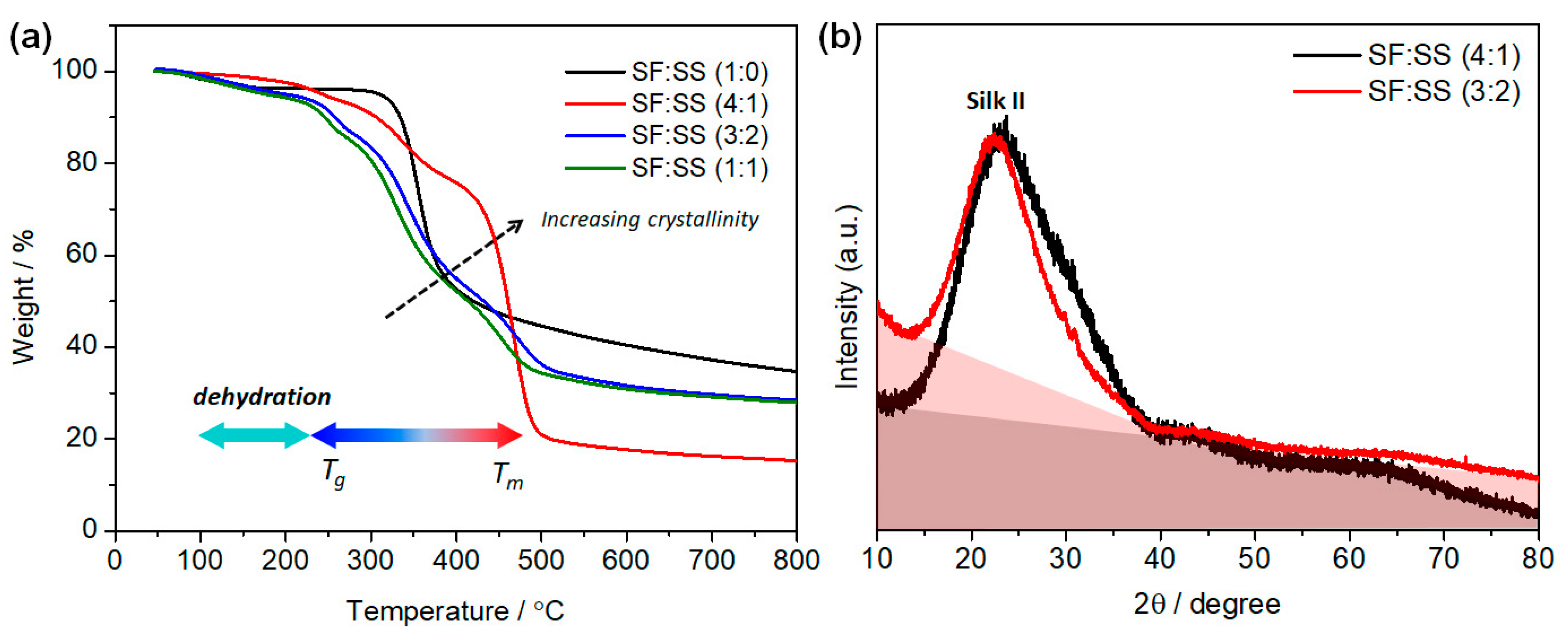
3.4. Thermal Properties of SF:SS Composite Adsorbent

The thermal properties and stability of the porous SF:SS composite were assessed using thermogravimetric (TGA) analysis. The TGA curves of pristine SF and SF:SS composites are presented in Figure 5a. A minor weight loss up to 225 °C was observed for all samples, due to dehydration. All SF:SS composites start to decompose at 242.5 °C, and the apparent weight loss temperature is found to be 288.95 °C, which is mainly due to the prolonged dehydration and depolymerization [44,45]. Here, the SF:SS (4:1) is considered thermally more stable than pristine SF, where SF:SS (4:1) significantly decomposes at 411.74 °C. In addition, compared with SF:SS (1:0) and SF:SS (1:1), SF:SS (3:2) shows a slightly higher decomposition temperature at 301.39 °C, which may be due to the stable β-sheet structure [46].
As typically found in semi-crystalline polymer material, two thermal transitions can be observed, including glass transition temperature (Tg) and melting temperature (Tm). Addition of SS in the composite deflects the TGA curve of pristine SF, indicating that the crystallinity decreases. As reported, the thermal decomposition temperature of SF is affected by its structural and morphological properties, e.g., different molecular conformations [47]. The decomposition temperature of the well-oriented β-sheet structure of silk fibers is marked above 300 °C and thermally degrades starting at 290 °C. It is interesting to note that the SF:SS (4:1) quite remarkably shifts the decomposition temperature at ~450 °C, whereas only a minor shift is observed for SF:SS (3:2) and SF:SS (1:1). This again reflects that the crystallinity of SF:SS (4:1) may be enhanced and the slower decomposition rate is due to the released heat to the environment through the large pore volume network in the SF:SS (4:1) structure. Higher crystallinity of SF:SS (4:1) is further corroborated by the X-ray diffraction spectrum (Figure 5b). The diffraction peaks at 25º for both SF:SS (41) and SF:SS (3:2) indicate the presence of the silk II conformation of SF. Nonetheless, the diffraction spectrum of SF:SS (4:1) exhibits a lower amorphous background (from the highlighted area under the curve baseline) than SF:SS (3:2). Hence, it is consistent with the TGA analysis that SF:SS (4:1) shows higher crystallinity than other composites.

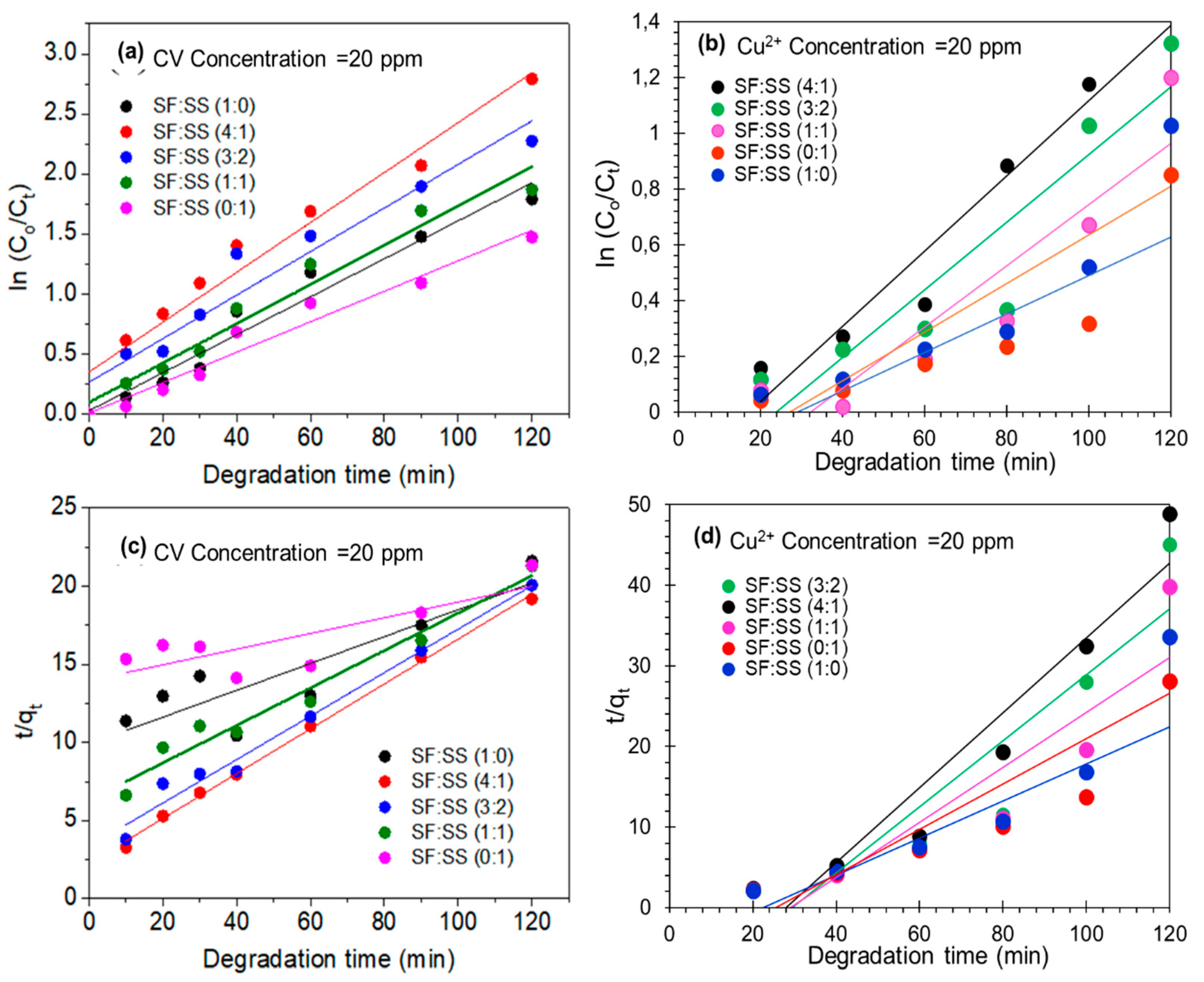
3.5. Adsorption Kinetics of Crystal Violet and Cu2+ onto SF:SS Composite

As the kinetic of adsorption is essential in practical application, the adsorption rate of organic pollutant, i.e., crystal violet (CV) and heavy metal (Cu2+), was assessed at various initial dye concentrations at pH 7 and at the room temperature. As can be seen in Figure 6a, the CV is rapidly adsorbed by SF:SS during the first 15 min and the adsorption slows down until the equilibrium condition is reached in about 1 h. This rapid dye adsorption at the initial stage is due to the strong electrostatic attraction between the surface of SF:SS biosorbent and cationic CV molecule because the SF:SS possesses many adsorption sites with a negative dipole, e.g., hydroxyl, and carboxylic groups [48]. The subsequent slow adsorption is caused by the limited surface adsorption sites of SF:SS and the repulsive forces between the soluble CV molecules on the solid and liquid phase. The CV molecules gradually penetrate the interior of SF:SS and are slowly adsorbed by the internal binding sites. Quantitative analysis of the adsorption kinetics of CV and Cu2+ based on the pseudo-first order and pseudo-second-order kinetic models are summarized in Table 2.
As shown, the experimental data best fit the pseudo-first-order kinetic model and hence, physisorption of CV onto SF:SS composite is more dominant than chemisorption. It is in a good agreement with the abovementioned hypothesis that electrostatic interaction facilitates the weak adsorption on the composite surface. Here, the highest adsorption rate is found at 21.85 min−1 for SF:SS (4:1). The large intercept value of the linear fit indicates that the external mass transfer is also crucial in the rate-controlling step for CV adsorption onto the SF:SS composite. Similar to the case of Cu2+ metal adsorption, the correlation coefficient (R2 = 0.957) calculated with pseudo-first-order kinetic of SF:SS (4:1) is higher than that (R2 = 0.917) calculated with the pseudo-second-order kinetic model (see Figure 6b,d)). In addition, the highest adsorption rate is found at 17.23 min−1 for Cu2+ metal ions onto SF:SS (4:1). Thus, the results suggest that the pseudo-first-order kinetic model fits well with the adsorption process of Cu2+ metal ions onto SF:SS (4:1).

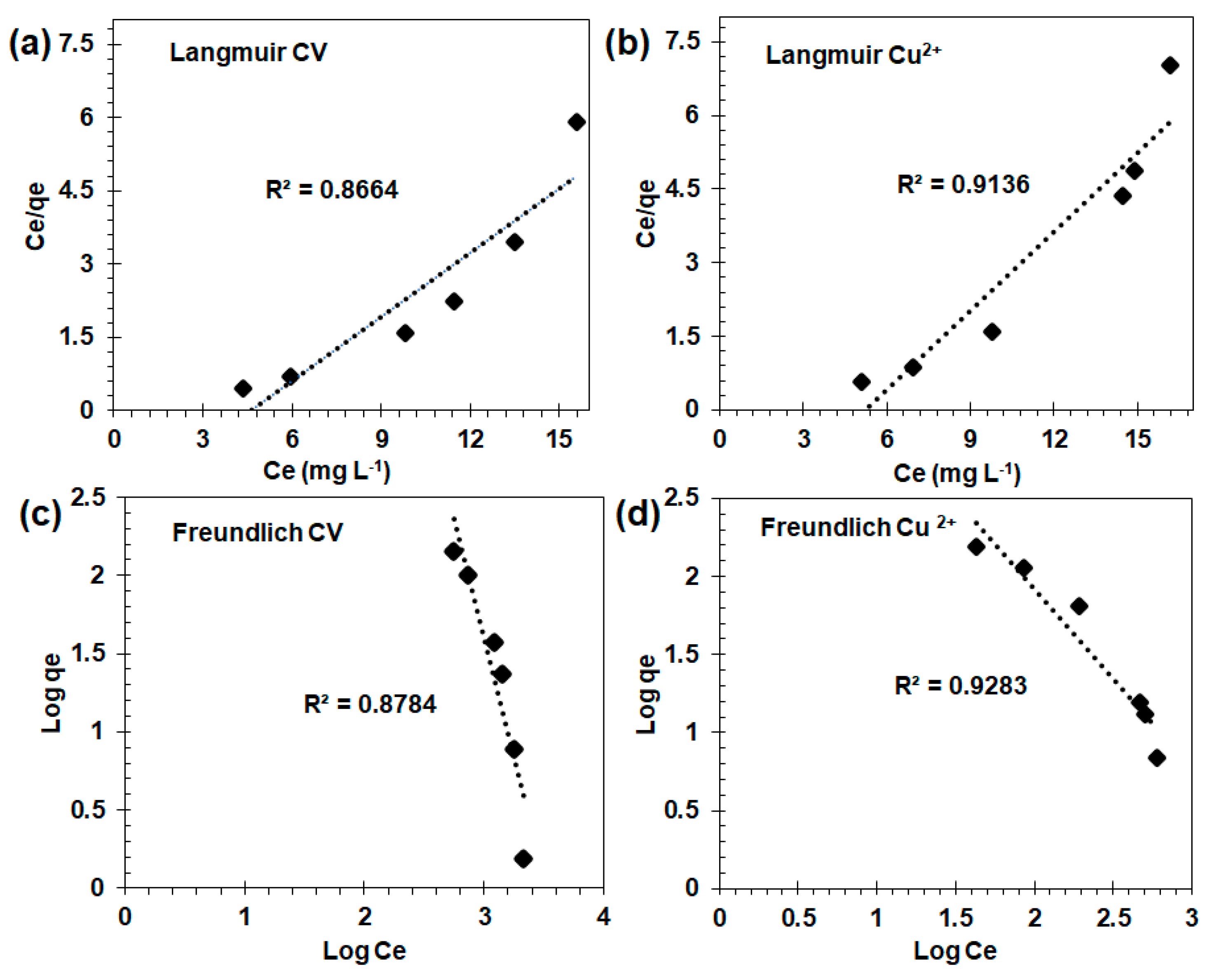
3.6. Adsorption Isotherm and Mechanism of CV and Cu2+ onto SF:SS Composite

Further evaluation was directed to estimate the adsorption capacity of SF:SS composite from the adsorption isotherm of CV and Cu2+. For this adsorption isotherm test, only SF:SS (4:1) was evaluated, which showed the best physical properties and the highest adsorption rate amongst the investigated samples. Langmuir and Freundlich adsorption isotherms were used to fit the experimental data of Cu2+ adsorption. The Langmuir adsorption isotherm model was developed based on monolayer adsorption mechanism in which the energy of adsorption system is considered constant. Meanwhile, Freundlich adsorption isotherm was developed for the heterogeneous system, which is based on the multilayer adsorption of the adsorbate on the surface. In order to assess the adsorption isotherm, the SF:SS (4:1) was used with the dosage of 150 mg and contact time of 120 min. The Langmuir adsorption isotherm is evaluated from the plot of Ce/qe vs. Ce (mg·L−1) as shown in Figure 7a,b, whereas the Freundlich adsorption isotherm was evaluated from the logarithmic plot of qe vs. Ce (Figure 7c,d). Adsorption parameters determined from both isotherm models are summarized in Table 3.
For CV adsorption, the result reveals that the adsorption isotherm of SF:SS (4:1) best fits with the Freundlich isotherm model (R2 = 0.878), yielding an adsorption capacity of 5.229 mg·g−1 (Table 3). Because 1/n is 0.711, this indicates that n > 1 for CV adsorption on SF:SS composites and, hence, consistent with kinetic analysis that physisorption is the dominant adsorption mechanism [49,50]. In contrast to the results obtained for CV, the adsorption isotherm of Cu2+ on SF:SS (4:1) linearly fits both Langmuir and Freundlich models (Figure 7b,d). Despite the on-par R2 value, the Freundlich model was found slightly better than Langmuir model for Cu2+ adsorption on SF:SS (4:1), as indicated by the higher R2 value (R2 = 0.928 vs. 0.913). Thus, the adsorption mechanism of the Cu2+ on the SF:SS composite can be explained by the fact that both chemisorption and physisorption possibly occur [49,50].
Further evidence of both chemisorption and physisorption occurring for Cu2+ onto SF:SS biocomposite adsorbent are depicted in Figure 8. Figure 8a displays the post operando FTIR spectra of various SF:SS composites upon Cu2+ adsorption. Compared to IR spectra of SF:SS before Cu2+ adsorption, several changes in the absorption feature in FTIR are observed and shown in the highlighted region in Figure 8a. The IR absorption bands at 2919 and 2845 cm−1, which are associated with C-H stretching, increase in intensity, indicating an altered conformation of SF. The structural change of the IR band associated with the β sheet at 1157, 1238, and 1370 cm−1 is also observed. IR bands at 700 and 469 cm−1 are altered upon Cu2+ adsorption and this can be attributed to strong stretching of metal-oxygen vibration [51], i.e., the formation of the Cu-O bond is indicative of chemisorption. Other evidence from the XRD pattern before and after Cu2+ adsorption shows that there is no significant change in the crystal structure and crystallinity of SF:SS (4:1). The slight shift in the silk II diffraction peak may originate from the micro-strain of SF:SS crystal induced by physisorption. Additional X-ray diffraction peaks at 26.7, 30.1, 31.4, 33.7, 35.5, 37.3, 38.2, 41.2, and 43.8º are found for SF:SS (4:1) after Cu2+ adsorption and these diffraction patterns are consistent with the diffraction pattern of Cu2+ originating from CuSO4 [52].
As SF is an amphoteric polymer, physisorption of Cu2+ and the positively charged CV may result from a weak electrostatic interaction between Cu2+ and the negatively charged R-C-OO in the SF-polymer backbone. Furthermore, the chemisorption of Cu2+ on the SF:SS surface may originate from a complex reaction between the Cu2+ ion and the chelating phosphonic acid groups from the phytic acid cross-linker [53]. The adsorption mechanism of CV and Cu2+ on SF:SS composite is simply illustrated in Figure 9.
Table 4 summarizes the performance of the SF:SS composite biosorbent compared to other SF-based adsorbents prepared using comparable and relevant methods [11,12,54]. Compared to SF and SF:PEI adsorbent [11], which yield maximum Cu2+ adsorption capacities of 20 and 160 mg·g−1, respectively, the SF:SS (4:1) examined here performs comparably and achieves even better Cu2+ adsorption capacity. Nonetheless, the results at hand, particularly regarding the adsorption of organic dye pollutants, are considered lower than those of graphene oxide-modified SF adsorbents, as previously reported [12,54]. These reported results inspire future efforts to improve adsorption capacity of SF:SS biopolymer composite by incorporating carbon nanomaterials, e.g., (reduced) graphene oxide and carbon nanotubes. A further comparison of adsorption capacity with other classes of adsorbent was carried out as follows: The present results of SF:SS (4:1) show better CV adsorption capacity of 83.31 mg·g−1 (according to the Langmuir adsorption isotherm) compared to the biochar derived from palm-kernel shell [55]. For Cu2+ adsorption, the SF:SS biocomposite adsorbent exhibits better adsorption capacity, of up to 73.22 mg·g−1, than that of algae-based bioadsorbent, which showed an adsorption capacity of 42.25 mg·g−1 [56]. This maximum Cu2+ adsorption capacity is, however, comparably lower than that of diethylenetriamine-modified polyacrilonitrile (DETA-PAN) fibers, which shows a maximum Cu2+ adsorption capacity up to 112.3 mg·g−1 [57].

3.7. Effect of pH Solution on Cu2+ Removal Using SF:SS Composites

Here, the effect of pH is considered one of the important parameters for heavy metal removal. The removal dependence of Cu2+ on the SF:SS surface on the initial pH of the solution is depicted in Figure 10. The pH of aqueous solution substantially affects the adsorption efficiency as protons will not only impact copper ions, but also lead to protonation and deprotonation of the functional groups on the SF:SS surface [58].
It is shown that, irrespective of the SF:SS composition, the optimum pH is 5.5 for Cu2+ removal. In more acidic conditions, i.e., pH lower than 5.5, a higher concentration of H3O+ ions will compete with Cu2+ for exchanging cations on the surface of the SF:SS bioadsorbent. Therefore, the Cu2+ removal capacity decreases. Under the condition of pH > 5.5, a high concentration of OH leads to the precipitation of Cu2+ ions by forming copper hydroxide. This precipitation significantly reduces the adsorption rate and, hence, decreases the removal capacity.

4. Conclusions

Various 3-D porous structures of silk fibroin/soursop seed (SF:SS) biocomposite adsorbent were successfully prepared by the freeze-drying method using a natural cross-linker of phytic acids available in the SS powder. The characterization results show that the SF:SS biocomposite adsorbent features a mesoporous structure. Changing the composition of SF:SS alters the structure of the 3-D porous networks, where SF:SS (4:1) exhibits the largest average pore diameter, pore volume, and specific surface area. The kinetic study indicated that the adsorption of organic molecules follows the pseudo-first-order kinetic model, which provided the best correlations with the experimental data. The adsorption isotherm of both the organic molecule and heavy metal best fits the Freundlich isotherm model, indicating the dominance of physisorption rather than chemisorption. Our focus in the future will be the detailed dynamic of the closing and opening mechanism of the mesopore structure within the SF:SS biocomposite adsorbent, adsorption capacity enhancement utilizing carbon nanomaterials, and pH-dependent study of the kinetics and adsorption isotherm.

Supplementary Materials

The following are available online at https://0-www-mdpi-com.brum.beds.ac.uk/article/10.3390/environments8110127/s1, SEM images of SF:SS at low magnification, UV/vis absorption data, photograph of decolorized solution using SF:SS bioadsorbent.

Author Contributions

The contributions of each author are as follows: Conceptualization, L.E. and R.A.W.; Methodology, L.E. and R.T.D.; Validation, L.E. and R.A.W.; Formal Analysis, R.T.D.; Investigation, R.A.W. and A.H.; Resources, A.H.; Data Curation, L.E.; Writing—Original Draft Preparation, L.E.; Writing—Review and Editing, R.A.W., L.E., A.H., R.N., W.W., T.E.; Visualization, R.A.W.; Supervision, L.E. and R.A.W.; Project Administration, L.E., T.E.; Funding Acquisition, L.E., T.E. All authors have read and agreed to the published version of the manuscript.

Funding

This work was supported by Kurita Water Environment Foundation (KWEF) Grant Number 19Pid021 provided for L.E.

Institutional Review Board Statement

Not applicable.

Informed Consent Statement

Not applicable.

Data Availability Statement

The data presented in this study are available in this article and Supplementary Materials.

Acknowledgments

Financial support from the Indonesian Endowment Fund for Education (LPDP) under World Class Professor Program contract No. 2817/E4.1/KK.04.05/2021 is gratefully acknowledged. Technical assistance was received from Central Mineral and Advanced Material Laboratory of Malang State University (UNM), State University of Semarang (UNNES).

Conflicts of Interest

The authors declare no competing financial interest or personal relationships that could have appeared to influence the work reported in this paper.

References

  1. Karbarz, M.; Khalil, A.M.; Wolowicz, K.; Kaniewska, K.; Romanski, J.; Stojek, Z. Enhancement of adsorption characteristics of Cr (III) and Ni (II) by surface modification of jackfruit peel biosorbent. J. Environ. Chem. Eng. 2018, 6, 3962–3970. [Google Scholar] [CrossRef]
  2. Crini, G.; Lichtfouse, E. Advantages and disadvantages of techniques used for wastewater treatment. Environ. Chem. Lett. 2019, 17, 145–155. [Google Scholar] [CrossRef]
  3. Dai, Y.; Sun, Q.; Wang, W.; Lu, L.; Liu, M.; Li, J.; Yang, S.; Sun, Y.; Zhang, K.; Xu, J.; et al. Utilizations of agricultural waste as adsorbent for the removal of contaminants: A review. Chemosphere 2018, 211, 235–253. [Google Scholar] [CrossRef] [PubMed]
  4. Kyzas, G.Z.; Kostoglou, M. Green adsorbents for wastewaters: A critical review. Materials 2014, 7, 333–364. [Google Scholar] [CrossRef] [PubMed]
  5. Meili, L.; Lins, P.V.S.; Costa, M.T.; Almeida, R.L.; Abud, A.K.S.; Soletti, J.I.; Dotto, G.L.; Tanabe, E.H.; Sellaoui, L.; Carvalho, S.H.V.; et al. Adsorption of methylene blue on agroindustrial wastes: Experimental investigation and phenomenological modelling. Prog. Biophys. Mol. Biol. 2019, 141, 60–71. [Google Scholar] [CrossRef] [PubMed]
  6. Sharma, S.; Tiwari, D.P.; Pant, K.K. Model-fitting approach for methylene blue dye adsorption on Camelina and Sapindus seeds-derived adsorbents. Adsorpt. Sci. Technol. 2016, 34, 565–580. [Google Scholar] [CrossRef]
  7. Tang, R.; Dai, C.; Li, C.; Liu, W.; Gao, S.; Wang, C. Removal of methylene blue from aqueous solution using agricultural residue walnut shell: Equilibrium, kinetic, and thermodynamic studies. J. Chem. 2017, 2017, 8404965. [Google Scholar] [CrossRef] [Green Version]
  8. Safa, Y.; Bhatti, H.N.; Sultan, M.; Sadaf, S. Synthesis, characterization and application of wheat bran/zinc aluminium and tea leaves waste/zinc aluminium biocomposites: Kinetics and thermodynamics modeling. Desalin. Water Treat. 2016, 57, 5914–5925. [Google Scholar] [CrossRef]
  9. Wang, H.; Chu, Y.; Fang, C.; Huang, F.; Song, Y.; Xue, X. Sorption of tetracycline on biochar derived from rice straw under different temperatures. PLoS ONE 2017, 12, 0182776. [Google Scholar] [CrossRef]
  10. Obayomi, K.S.; Bello, J.O.; Nnoruka, J.S.; Adediran, A.A.; Olajide, P.O. Development of low-cost bio-adsorbent from agricultural waste composite for Pb (II) and As (III) sorption from aqueous solution. Cogent Eng. 2019, 6, 1687274. [Google Scholar] [CrossRef]
  11. Godiya, C.B.; Cheng, X.; Deng, G.; Li, D.; Lu, X. Silk fibroin/polyethylenimine functional hydrogel for metal ion adsorption and upcycling utilization. J. Environ. Chem. Eng. 2019, 7, 102806. [Google Scholar] [CrossRef]
  12. Wang, S.; Ning, H.; Hu, N.; Huang, K.; Weng, S.; Wu, X.; Wu, L.; Liu, J.; Alamusi, A. Preparation and characterization of graphene oxide/silk fibroin hybrid aerogel for dye and heavy metal adsorption. Compos. Part B Eng. 2019, 163, 716–722. [Google Scholar] [CrossRef]
  13. Rastogi, S.; Kandasubramanian, B. Progressive trends in heavy metal ions and dyes adsorption using silk fibroin composites. Environ. Sci. Pollut. Res. 2020, 27, 210–237. [Google Scholar] [CrossRef]
  14. Zhang, K.H.; Wang, H.S.; Huang, C.; Su, Y.; Mo, X.M.; Ikada, Y. Fabrication of silk fibroin blended P (LLA-CL) nanofibrous scaffolds for tissue engineering. J. Biomed. Mater. Res. Part A 2010, 93, 984–993. [Google Scholar] [CrossRef]
  15. Yang, Y.M.; Zhao, Y.H.; Gu, Y.; Yan, X.L.; Liu, J.; Ding, F.; Gu, X.S. Degradation behaviors of nerve guidance conduits made up of silk fibroin in vitro and in vivo. Polym. Degrad. Stab. 2009, 94, 2213–2220. [Google Scholar] [CrossRef]
  16. Li, C.M.; Vepari, C.; Jin, H.J.; Kim, H.J.; Kaplan, D.L. Electrospun silk-BMP-2 scaffolds for bone tissue engineering. Biomaterials 2006, 27, 3115–3124. [Google Scholar] [CrossRef]
  17. Rajkhowa, R.; Gil, E.S.; Kluge, J.; Numata, K.; Wang, L.J.; Wang, X.D.; Kaplan, D.L. Reinforcing silk scaffolds with silk particles. Macromol. Biosci. 2010, 10, 599–611. [Google Scholar] [CrossRef] [Green Version]
  18. Wenk, E.; Meinel, A.J.; Wildy, S.; Merkle, H.P.; Meinel, L. Microporous silk fibroin scaffolds embedding PLGA microparticles for controlled growth factor delivery in tissue engineering. Biomaterials 2009, 30, 2571–2581. [Google Scholar] [CrossRef]
  19. Mandal, B.B.; Kundu, S.C. Non-bioengineered silk fibroin protein 3D scaffolds for potential biotechnological and tissue engineering applications. Macromol. Biosci. 2008, 8, 807–818. [Google Scholar] [CrossRef] [PubMed]
  20. Lu, Q.; Hu, K.; Feng, Q.L.; Cui, F.Z. Growth of fibroblast and vascular smooth muscle cells in fibroin/collagen scaffold. Mater. Sci. Eng. C 2009, 29, 2239–2245. [Google Scholar] [CrossRef]
  21. Nazarov, R.; Jin, H.J.; Kaplan, D.L. Porous 3-D scaffolds from regenerated silk fibroin. Biomacromolecules 2004, 5, 718–726. [Google Scholar] [CrossRef]
  22. Wang, Y.; Bella, E.; Lee, C.S.D.; Migliaresi, C.; Pelcastre, L.; Schwartz, Z.; Boyan, B.D.; Motta, A. The synergistic effects of 3-D porous silk fibroin matrix scaffold properties and hydrodynamic environment in cartilage tissue regeneration. Biomaterials 2010, 31, 4672–4681. [Google Scholar] [CrossRef] [PubMed]
  23. Li, M.; Zhang, C.; Lu, S.; Wu, Z.; Yan, H. Study on porous silk fibroin materials: 3. Influence of repeated freeze–thawing on the structure and properties of porous silk fibroin materials. Polym. Adv. Technol. 2002, 13, 605–610. [Google Scholar] [CrossRef]
  24. Li, M.; Lu, S.; Wu, Z.; Tan, H.; Minoura, N.; Kuga, S. Structure and properties of silk fibroin–poly (vinyl alcohol) gel. Int. J. Biol. Macromol. 2002, 30, 89–94. [Google Scholar] [CrossRef]
  25. Cassinelli, C.; Cascardo, G.; Morra, M.; Draghi, L.; Motta, A.; Catapano, G. Physical-chemical and biological characterization of silk fibroin-coated porous membranes for medical applications. Int. J. Artif. Organs 2006, 29, 881–892. [Google Scholar]
  26. Karageorgiou, V.; Tomkins, M.; Fajardo, R.; Meinel, L.; Snyder, B.; Wade, K.; Chen, J.; Vunjak-Novakovic, G.; Kaplan, D.L. Porous silk fibroin 3-D scaffolds for delivery of bone morphogenetic protein-2 in vitro and in vivo. J. Biomed. Mater. Res. Part A 2006, 78, 324–334. [Google Scholar] [CrossRef]
  27. Tamada, Y. New process to form a silk fibroin porous 3-D structure. Biomacromolecules 2005, 6, 3100–3106. [Google Scholar] [CrossRef] [PubMed]
  28. Liu, J.; Chen, H.; Wang, Y.; Li, G.; Zheng, Z.; Kaplan, D.L.; Wang, X.; Wan, X. Flexible Water-Absorbing Silk-Fibroin Biomaterial Sponges with Unique Pore Structure for Tissue Engineering. ACS Biomater. Sci. Eng. 2020, 6, 1641–1649. [Google Scholar] [CrossRef]
  29. Teimouri, A.; Ebrahimi, R.; Emadi, R.; Beni, B.H.; Chermahini, A.N. Nano-composite of silk fibroin–chitosan/Nano ZrO2 for tissue engineering applications: Fabrication and morphology. Int. J. Biol. Macromol. 2015, 76, 292–302. [Google Scholar] [CrossRef] [PubMed]
  30. Zhou, W.; Huang, H.; Du, S.; Huo, Y.; He, J.; Cui, S. Removal of copper ions from aqueous solution by adsorption onto novel polyelectrolyte film-coated nanofibrous silk fibroin non-wovens. Appl. Surf. Sci. 2015, 345, 169–174. [Google Scholar] [CrossRef]
  31. Gao, A.; Xie, K.; Song, X.; Zhang, K.; Hou, A. Removal of the heavy metal ions from aqueous solution using modified natural biomaterial membrane based on silk fibroin. Ecol. Eng. 2017, 99, 343–348. [Google Scholar] [CrossRef]
  32. Ki, C.S.; Gang, E.H.; Um, I.C.; Park, Y.H. Nanofibrous membrane of wool keratose/silk fibroin blend for heavy metal ion adsorption. J. Memb. Sci. 2007, 302, 20–26. [Google Scholar] [CrossRef]
  33. Zhang, C.; Su, J.; Zhu, H.; Xiong, J.; Liu, X.; Li, D.; Chen, Y.; Li, Y. The removal of heavy metal ions from aqueous solutions by amine functionalized cellulose pretreated with microwave-H2O2. RSC Adv. 2017, 7, 34182–34191. [Google Scholar] [CrossRef] [Green Version]
  34. Zhang, M.; Yin, Q.; Ji, X.; Wang, F.; Gao, X.; Zhao, M. High and fast adsorption of Cd (II) and Pb (II) ions from aqueous solutions by a waste biomass based hydrogel. Sci. Rep. 2020, 10, 3285. [Google Scholar] [CrossRef]
  35. Mallampati, R.; Xuanjun, L.; Adin, A.; Valiyaveettil, S. Fruit Peels as Efficient Renewable Adsorbents for Removal of Dissolved Heavy Metals and Dyes from Water. ACS Sustain. Chem. Eng. 2015, 3, 1117–1124. [Google Scholar] [CrossRef]
  36. Ho, Y.S.; McKay, G. Pseudo-second order model for sorption processes. Process Biochem. 1999, 34, 451–465. [Google Scholar] [CrossRef]
  37. Zhang, F.; Lu, Q.; Yue, X.; Zuo, B.; Qin, M.; Li, F.; Kaplan, D.L.; Zhang, X. Regeneration of high-quality silk fibroin fiber by wet spinning from CaCl2–formic acid solvent. Acta Biomater. 2015, 12, 139–145. [Google Scholar] [CrossRef]
  38. Palumbo, F.S.; Fiorica, C.; Pitarresi, G.; Agnello, S.; Giammona, G. Interpenetrated 3D porous scaffolds of silk fibroin with an amino and octadecyl functionalized hyaluronic acid. RSC Adv. 2015, 5, 61440–61448. [Google Scholar] [CrossRef]
  39. Asakura, T.; Yao, J.; Yamane, T.; Umemura, K.; Ulrich, A.S. Heterogeneous Structure of Silk Fibers from Bombyx mori Resolved by 13C Solid-State NMR Spectroscopy. J. Am. Chem. Soc. 2002, 124, 8794–8795. [Google Scholar] [CrossRef] [PubMed]
  40. Sui, Z.; King, W.J.; Murphy, W.L. Protein-Based Hydrogels with Tunable Dynamic Responses. Adv. Funct. Mater. 2008, 18, 1824–1831. [Google Scholar] [CrossRef]
  41. Coria-Téllez, A.V.; Montalvo-Gónzalez, E.; Yahia, E.M.; Obledo-Vázquez, E.N. Annona muricata: A comprehensive review on its traditional medicinal uses, phytochemicals, pharmacological activities, mechanisms of action and toxicity. Arab. J. Chem. 2018, 11, 662–691. [Google Scholar] [CrossRef] [Green Version]
  42. Badrie, N.; Schauss, A.G. Biactive Foods in Promoting Health; Oxford Academic Press: Oxford, UK, 2009; pp. 621–643. [Google Scholar]
  43. Tashi, Z.; Zare, M.; Parvin, N. Application of phytic-acid as an in-situ crosslinking agent in electrospun gelatin-based scaffolds for skin tissue engineering. Mater. Lett. 2020, 264, 127275. [Google Scholar] [CrossRef]
  44. Ma, M.; Ayaz, P.; Jin, W.; Zhou, W. Improving the Color Stability of Naturally Colored Silk by Cross-Linking the Sericin with Phytic Acid. Int. J. Polym. Sci. 2019, 2019, 6936437. [Google Scholar] [CrossRef]
  45. Lawrence, B.D.; Wharram, S.; Kluge, J.A.; Leisk, G.G.; Omenetto, F.G.; Rosenblatt, M.I.; Kaplan, D.L. Effect of hydration on silk film material properties. Macromol. Biosci. 2010, 10, 393–403. [Google Scholar] [CrossRef] [PubMed] [Green Version]
  46. Yao, D.; Liu, H.; Fan, Y. Fabrication of water-stable silk fibroin scaffolds through self-assembly of proteins. RSC Adv. 2016, 6, 61402–61409. [Google Scholar] [CrossRef]
  47. Qi, Y.; Wang, H.; Wei, K.; Yang, Y.; Zheng, R.Y.; Kim, I.; Zhang, K.Q. A review of structure construction of silk fibroin biomaterials from single structures to multi-level structures. Int. J. Mol. Sci. 2017, 18, 237. [Google Scholar] [CrossRef]
  48. Kim, U.J.; Park, J.; Li, C.; Jin, H.J.; Valluzzi, R.; Kaplan, D.L. Structure and properties of silk hydrogels. Biomacromolecules 2004, 5, 786–792. [Google Scholar] [CrossRef]
  49. Kim, S.; Park, C.M.; Jang, M.; Son, A.; Her, N.; Yu, M.; Snyder, S.; Kim, D.H.; Yoon, Y. Aqueous removal of inorganic and organic contaminants by graphene-based nanoadsorbents: A review. Chemosphere 2018, 212, 1104–1124. [Google Scholar] [CrossRef] [PubMed]
  50. Sato, T.; Seki, T.; Yokoyama, S.; Ito, S. Adsorption of cesium ion on silk fibroin in aqueous solution. Trans. Mater. Res. Soc. Jpn. 2017, 42, 19–22. [Google Scholar] [CrossRef] [Green Version]
  51. Djordjevíc, C. Metal-oxygen vibration modes in the infra-red spectra of aluminium, gallium and indium tris-acetylacetonates. Spectrochim. Acta 1961, 17, 448–453. [Google Scholar] [CrossRef]
  52. Derun, E.M.; Tugrul, N.; Senberber, F.T.; Kipcak, A.S.; Piskin, S. The Optimization of Copper Sulfate and Tincalconite Molar Ratios on the Hydrothermal Synthesis of Copper Borates. Int. J. Chem. Mol. Eng. 2014, 8, 1152–1156. [Google Scholar] [CrossRef]
  53. Taschner, I.S.; Aubuchon, E.; Schrage, B.R.; Ziegler, C.J.; van der Est, A. Synthesis and structural studies of copper (II) complex with N2S2 based N-substituted pendant phosphonic acid arms. Dalton Trans. 2020, 11, 3545–3552. [Google Scholar] [CrossRef] [PubMed]
  54. Bruder, V.; Ludwig, T.; Opitz, S.; Christoffels, R.; Fischer, T.; Maleki, H. Hierarchical Assembly of Surface Modified Silk Fibroin Biomass into Micro-, and Milli-Metric Hybrid Aerogels with Core-Shell, Janus, and Composite Configurations for Rapid Removal of Water Pollutants. Adv. Mater. Interfaces 2021, 8, 2001892. [Google Scholar] [CrossRef]
  55. Kyi, P.P.; Quansah, J.O.; Lee, C.G.; Moon, J.K.; Park, S.J. The Removal of Crystal Violet from Textile Wastewater Using Palm Kernel Shell-Derived Biochar. Appl. Sci. 2020, 10, 2251. [Google Scholar] [CrossRef] [Green Version]
  56. Pham, B.N.; Kang, J.K.; Lee, C.G.; Park, S.J. Removal of Heavy Metals (Cd2+, Cu2+, Ni2+, Pb2+) from Aqueous Solution Using Hizikia fusiformis as an Algae-Based Bioadsorbent. Appl. Sci. 2021, 11, 8604. [Google Scholar] [CrossRef]
  57. Aung, K.T.; Hong, S.H.; Park, S.J.; Lee, C.G. Removal of Cu (II) from Aqueous Solutions Using Amine-Doped Polyacrylonitrile Fibers. Appl. Sci. 2020, 10, 1738. [Google Scholar] [CrossRef] [Green Version]
  58. Dragan, E.S.; Perju, M.M.; Dinu, M.V. Preparation and characterization of IPN composite hydrogels based on polyacrylamide and chitosan and their interaction with ionic dyes. Carbohydr. Polym. 2012, 88, 270–281. [Google Scholar] [CrossRef]
Figure 1. (a) Photograph of various SF:SS composites. SEM images of SF:SS composites with increasing SS fraction, i.e., SS:SS ratio of (b) (1:0), (c) (4:1), (d) (3:2), and (e) (1:1). Inset of figures (be) reflects the corresponding enlarged microstructure to highlight the pore structure.
Environments 08 00127 g001
Figure 2. (a) N2 adsorption-desorption isotherm and (b) BJH pore distribution of various SF:SS composites.
Environments 08 00127 g002
Figure 3. FTIR spectra of various SF:SS composites with different composition.
Environments 08 00127 g003
Figure 4. The proposed structural formation of 3-D porous network in SF:SS composites, in which phytic acids in SS powder cross-links the unstructured fibrous arrangement of SF and creates the pore structure in the composites.
Environments 08 00127 g004
Figure 5. (a) TGA curves of various SF:SS composites with different composition. (b) X-ray diffraction pattern of SF:SS (4:1) and SF:SS (3:2).
Environments 08 00127 g005
Figure 6. The linear dependence of Ct/C0 on t based on the pseudo-first-order model for (a) CV and (b) Cu2+ adsorption, and (b) the linear dependence of t/Qt on t based on the pseudo-second-order model for (c) CV and (d) Cu2+ adsorption.
Environments 08 00127 g006
Figure 7. (a,b) Langmuir and (c,d) Freundlich adsorption isotherms of CV molecules and Cu2+ ions onto SF:SS (4:1) composite.
Environments 08 00127 g007
Figure 8. (a) FTIR spectra of SF:SS with different compositions after Cu2+ adsorption and (b) XRD spectra of SF:SS (4:1) before and after Cu2+ adsorption.
Environments 08 00127 g008
Figure 9. Schematic illustration of CV physisorption of CV and both physisorption and chemisorption of Cu2+ on the surface of SF:SS biocomposite adsorbent.
Environments 08 00127 g009
Figure 10. Removal capacity of Cu2+ using various SF:SS biocomposite adsorbents at different pH solutions.
Environments 08 00127 g010
Table 1. Specific surface area and pore properties of SF and composite sorbent at different SF:SS compositions.
SF:SS
Compositions
Average Pore
Diameter (nm)
Specific
Surface Area (m2·g−1)
Pore
Volume (cc·g−1)
SF:SS (1:0)2.175.330.00227
SF:SS (4:1)39.1919.470.00811
SF:SS (3:2)38.5717.190.00562
SF:SS (1:1)3.737.450.00528
Table 2. The parameters of the pseudo-first-order and pseudo-second-order models for the adsorption of CV and Cu2+ using SF:SS composite adsorbent.
Pollutant Bioadsorbent Composition k1 × 10 (min−1)R2k2 × 10 (min−1)R2
Crystal Violet
(20 mg·L−1)
SF:SS = (0:1)12.710.96454.190.9286
SF:SS = (1:0)15.820.96055.870.9295
SF:SS = (4:1)21.850.957614.650.8275
SF:SS = (3:2)18.190.94049.370.9101
SF:SS = (1:1)16. 340.96566.590.9379
Cu2+
(20 mg·L−1)
SF:SS = (0:1)7.180.75913.170.839
SF:SS = (1:0)10.820.82715.820.846
SF:SS = (4:1)17.230.95720.770.917
SF:SS = (3:2)15.760.85219.810.851
SF:SS = (1:1)11.610.83817.550.823
Table 3. The parameters of Langmuir and Freundlich isotherms for the adsorption of CV.
IsothermParameterCVCu2+
Langmuirqm (mg·g−1)83.3173.22
KL (mg·L−1)0.5370.283
R20.8660.913
FreundlichKF (mg·g−1)5.2297.164
1/n0.7110.673
R20.8780. 928
Table 4. Comparative results of SF-based biosorbent for dye and heavy metal adsorption.
Silk FibroinModel PollutantsAdsorption CharacteristicRef.
SF-PEI-2Cu2+Langmuir
KL = 0.14 (mg·L)−1
qmax = 186.7 mg·g−1
Freundlich
KF = 134.4 mg·g−1 (n = 19.2)
[54]
Methyl OrangeLangmuir
KL = 0.0061 (mg·L)−1
qmax = 811.3 mg·g−1
Freundlich
KF = 32.8 mg·g−1 (n = 2.09)
SF-PEI-2-GOCu2+Langmuir
KL = 0.23 (mg·L)−1
qmax = 171.6 mg·g−1
Freundlich
KF = 121.6 mg·g−1 (n = 17.3)
Methyl OrangeLangmuir
KL = 0.0046 (mg·L)−1
qmax = 791.9 mg·g−1
Freundlich
KF = 20.8 mg·g−1 (n = 1.88)
SF:PEI (5:5)Cu2+Langmuir
qmax = 160 mg·g−1
[11]
Methylene BlueLangmuir
qmax = 75 mg·g−1
SFCu2+Langmuir
qmax = 20 mg·g−1
SF0-GOMethylene BlueLangmuir
KL = 2.155 (mg·L)−1
qmax = 1411.194 mg·g−1
Freundlich
KF = 0.363 L·g−1 (n = 3.799)
[12]
SF20-GOMethylene BlueLangmuir
KL = 4.779 (mg·L)−1
qmax = 1521.6 mg·g−1
Freundlich
KF = 0.199 L·g−1 (n = 5.013)
SF:SSCu2+Langmuir
KL = 0.283 (mg·L)−1
qmax = 73.22 mg·g−1
Freundlich
KF = 7.164 mg·g−1 (n = 6.49)
This Work
Crystal VioletLangmuir
KL = 0.537 (mg·L)−1
qmax = 83.31 mg·g−1
Freundlich
KF = 5.229 mg·g−1 (n = 1.41)
Publisher’s Note: MDPI stays neutral with regard to jurisdictional claims in published maps and institutional affiliations.

