Article

Fast Diffraction Calculation for Spherical Computer-Generated Hologram Using Phase Compensation Method in Visible Range

1
School of Electronics and Information Engineering, Sichuan University, Chengdu 610065, China
2
School of Electrical Engineering, Seoul National University, Seoul 151-744, Korea
3
Center for Design Centric Engineering, Kyoto Institute of Technology, Kyoto 606-8585, Japan
*
Author to whom correspondence should be addressed.
Submission received: 31 July 2020 / Revised: 17 August 2020 / Accepted: 18 August 2020 / Published: 21 August 2020
(This article belongs to the Special Issue Incoherent Digital Holography)

Abstract

:
The synthesis of the spherical hologram has been widely investigated in recent years as it enables a large field of view both horizontally and vertically. However, there is an important issue of long time consumption in spherical computer-generated holograms (SCGHs). To address this issue, a fast diffraction calculation method is proposed for SCGH based on phase compensation (PC). In our method, a wavefront recording plane (WRP) near the SCGH is used to record the diffraction distribution from the object plane, and the phase difference is compensated point-to-point from the WRP to generate the SCGH, during which a nonuniform sampling method is proposed to greatly decrease the sampling rate and significantly accelerate the generation speed of SCGH. In this paper, there are three main contributions: (1) SCGHs with the resolution of full high-definition can be synthesized in visible range with reducing the sampling rate. (2) Due to the current difficulty of realizing holographic display with curved surfaces, our PC method provides an alternative approach to implement optical experiments of SCGH, which takes it closer to the practical applications of spherical holography. (3) The problem of time-consuming calculation of the propagation model between plane and sphere is solved firstly to our best knowledge.

1. Introduction

Holography is widely recognized as the most effective way to achieve true three-dimensional (3D) display because of its capacity to record both amplitude and phase information of 3D objects. Moreover, there are numerous researches about the implementation and improvement of holograms for practical use [1,2,3,4]. Computational holography is a technique based on digital computing and modern optics. It is extensively studied in recent years as it breaks the strict conditions of optical holography for the generation of holograms. The computer-generated holograms are synthesized and encoded by computer, which enables the recording of virtual 3D objects [5,6,7]. However, the inherent limitation of planar holography in field of view obstructs the achievement of holographic display with large viewing angle. In order to solve this problem, holograms with curved, including cylindrical, surfaces have been investigated [8,9,10,11,12,13,14,15]. As one of the most important curved-surface holograms, the spherical computer-generated hologram (SCGH) is considered ideal to enlarge the viewing angle on both horizontal and vertical directions. The full viewing zone is realized by recording and reconstructing the optical field of an object surrounded by a sphere, which provides potential to inspect the image of this object from arbitrary angles, and is thereby capable to realize omnidirectional reconstruction.
There are a number of achievements in the field of spherical holography [16,17,18,19,20,21]. However, the huge amount of data limits the computational time for the process of SCGH generation, which is one of the major obstacles to the practical application of spherical holography. To address this issue, several pieces of research associated with the speed enhancement of spherical hologram synthesis have been reported [17,18,19,20,21]. M. Tachiki et al. proposed a method for fast calculating the spherical hologram distribution using convolution algorithm based on fast Fourier transform (FFT) [17]. It approximated the diffracted optical field as the calculation result of a convolution integral, which enables FFT to shorten the total computing time. B. Jackin and T. Yatagai explored a fast calculation method of SCGH using spherical wave spectrum [18], which is based on wave propagation defined in spectral domain and in spherical coordinates. It uses only N ( l o g N ) 2 operations for calculations on N sampling points and can accelerate the computing process effectively. G. Li et al. proposed an acceleration method for SCGH calculation of real objects using graphics processing unit(GPU) [19]. It improved the calculation efficiency compared with the computation speed of central processing unit(CPU). Additionally, Y. Sando et al. introduced a spherical harmonic transform-based fast calculation algorithm for SCGH considering occlusion culling [20]. In this method, the diffraction integral is expressed in the form of the convolution integral, which can be calculated rapidly by performing spherical harmonic transform instead of FFT. It cuts down the computing time and removes occlusion as well. Besides, H. Cao and E. Kim applied SCGH to holographic video and proposed a faster generation method of holographic videos of objects moving in space using a spherical hologram-based 3D rotational motion compensation scheme [21], which provides another possible application of SCGH.
The methods above are basically devoted to the study of fast calculation methods of SCGH generated by concentric spherical surfaces. However, extremely high pixel resolution is required to satisfy the sampling theorem for the visible range of light wavelengths. For example, it is nearly 200,000 × 200,000 for wavelength λ = 632.8 nm when the radii of the inner and outer sphere are 1 cm and 10 cm, respectively, when calculated by convolution method [17]. Furthermore, the wavelength is set to λ = 300 μ m in order to reduce the sampling requirements to 256 × 512 pixels when using spherical wave spectrum method [18]. Compared with the sampling points of more than 4 × 10 10 for conventional SCGH in visible range, that of the proposed generation method is reduced to an acceptable level of 10 6 . Moreover, the spatial light modulator (SLM) with curved surface is difficult to realize so far, and reconstructing a spherical hologram by laser after printing it on a flexible film is still a challenging task today [18]. Given the staggering sampling points for the visible range of wavelengths required in the concentric-sphere model and the constraints of the optical materials and the production technology currently, it is difficult for practical application due to the long time consumption and unavailable holographic reconstruction equipment.
In this paper, a fast diffraction calculation method between plane and sphere for SCGH based on phase compensation (PC) is proposed. Our PC method can be summarized in two steps: First, a wavefront recording plane (WRP) is used to record the optical field propagated from the object plane. As the conventional plane-to-plane diffraction calculation method is adopted in this step, the number of sampling points of WRP is coincident with that of the adopted plane diffraction model. In the second step, the phase difference introduced by the optical path difference between WRP and SCGH is approximately compensated point-to-point in order to generate the SCGH, which means the number of sampling points is constant with that of WRP. Compared with the original point source (PS) method, few sampling points, good scalability, and significant acceleration performance are the absolute advantages of our PC method. Therefore, the problem of time-consuming calculation of the propagation model between plane and sphere is solved firstly to our best knowledge, which is different from accelerating at the expense of limiting the wavelength in the invisible micron band in the two concentric spherical propagation model. The feasibility of our method is verified by numerical simulations and optical experiments, and the error is analyzed by theory and simulations in this paper. The reconstruction quality is good regardless of the increase in the curvature of SCGH or the resolution of the object plane, even though it is an approximate method. Moreover, in this paper, an alternative approach using PC method to implement optical experiments of SCGH is provided by compensating the phase difference between SCGH and planar SLM before loading the hologram on the SLM for reconstruction, which makes it even closer to realize the practical applications of spherical holography.
This paper consists of four sections. In the Section 2, we introduce the PC method and analyze its error. The simulations and experiments are described in Section 3. Finally, we draw conclusions and discuss prospects in Section 4.

2. Methods

2.1. Propagation Model between Plane and Sphere

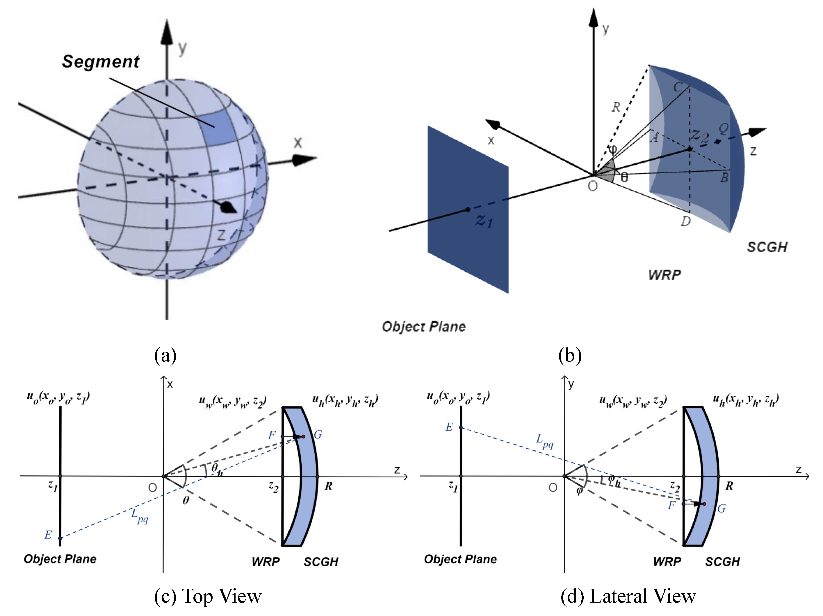
The schematic of the propagation model between plane and sphere is shown in Figure 1a,b: Figure 1a shows a segment of a spherical SCGH and Figure 1b is the detail propagation model of a segment SCGH. In Figure 1b, θ and φ are, respectively, the horizontal and vertical flare angles of WRP to the center of SCGH which determine the curvature of SCGH segment since the size of the WRP is fixed. Moreover, they correspond to A O B and C O D , respectively. In Figure 1c,d, θ h and φ h are the angles of the radial projection on x-z plane to z axis and the radial direction to x-z plane, respectively. The point source method is the traditional way to calculate the diffraction distribution of this model. It is especially time-consuming as its computational complexity is O ( N 2 ) when computing N sampling points. Unfortunately, there is not any fast calculation method so far. Therefore, we propose the PC method to accelerate the computation.
In the PC method, the propagation calculation between an object plane and an SCGH can be summarized in two steps: the diffraction from the object plane to the WRP near the spherical surface, and the phase compensation from the WRP to the SCGH. In the first step, the diffraction propagation from the object to WRP is calculated by any conventional plane-to-plane diffraction calculation method as the universality of our method, and we choose the angular spectrum method as an example. The second step is to compensate the phase difference due to the optical path difference between WRP and SCGH.

2.2. SCGH Generation by PC Method

The process of the SCGH generation by PC method consists of two steps: wavefront recording and phase compensation. In the first step, the diffraction distribution from the object plane to the WRP is recorded. Here, we take the angular spectrum method with FFT to calculate the diffraction distribution. The complex amplitude distribution u w ( x w , y w , z 2 ) of the WRP is expressed as
u w ( x w , y w , z 2 ) = F 1 { F { u o ( x o , y o , z 1 ) } · exp [ j 2 π λ z 1 ( λ f x o ) 2 ( λ f y o ) 2 ] } ,
where u o ( x o , y o , z 1 ) denotes the complex amplitude distribution of object plane; z = z 2 z 1 shows the propagation distance between object plane and WRP; ( f x 0 , f y o ) is the spacial frequency of the object plane in the directions of x and y axis; λ is the wavelength; and F { · } and F 1 { · } are the Fourier and inverse Fourier operators, respectively.
In the second step, the phase difference caused by the optical path difference between WRP and SCGH is compensated to generate the SCGH, and the schematics of the generation process by PC method are shown in Figure 1c,d.
The phase difference is compensated point-to-point between the WRP and SCGH. The point G on the SCGH is the projection of point F in the direction of z axis. Note that each point on the WRP should be compensated to generate the SCGH, which means the sampling number of SCGH should be consistent with that of WRP. Based on this principle and the geometric relationship shown in Figure 1, the coordinate relationship between points on WRP and the corresponding projected points on SCGH can be given by
x h = x w , y h = y w , z h = R cos θ h cos φ h ,
where
θ h = arcsin x h R cos φ h , φ h = arcsin y h R .
The optical path difference between WRP and SCGH can be described as
d P C = z h z 2 .
Moreover, the complex amplitude of SCGH can be expressed by
u h ( x h , y h , z h ) = u w ( x w , y w , z 2 ) · exp ( j k d P C ) .
Note that the PC method described above is a fast method to approximately calculate the complex amplitude of SCGH in the propagation model between plane and sphere. It compensates the phase difference without the amplitude attenuation. Because of the limited curvature of the SCGH, the distance between WRP and SCGH is relatively small. Therefore, it can be considered that the phase difference is caused entirely by the geometric optical path discrepancy and the amplitude is nearly constant. The error between the PC method and the real propagation situation will be discussed in detail in Section 2.4 and simulated in Section 3.1.3.

2.3. Nonuniform Sampling

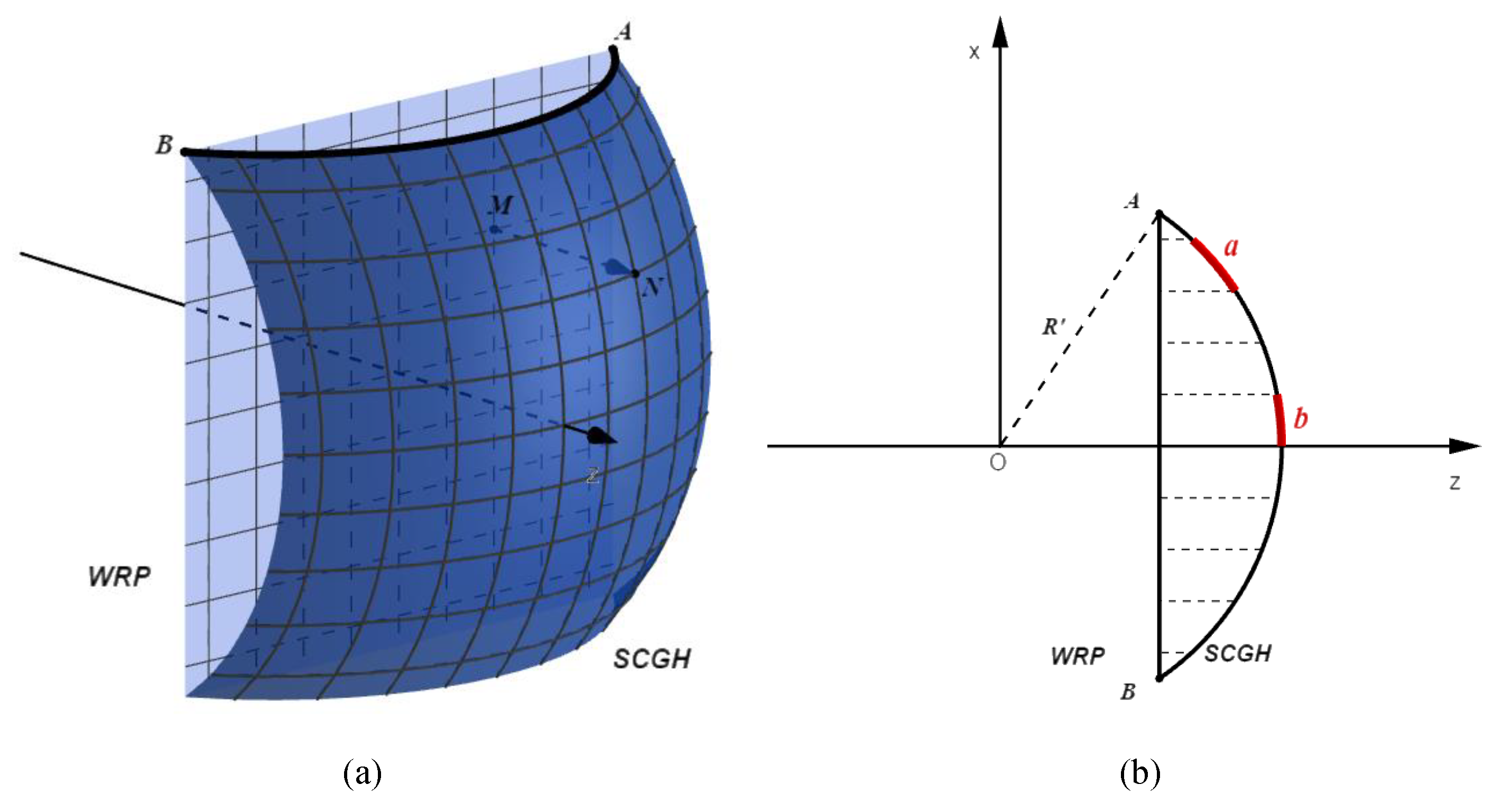
The schematic diagram of nonuniform sampling is shown in Figure 2. The sampling points on SCGH are unevenly distributed as the phase of SCGH is compensated point-to-point from WRP, as shown in Figure 2a, which means any two adjacent sampling points on SCGH should be equally spaced in the direction of x and y axis.
Taking an arc A B on SCGH as an example to explain the principle of nonuniform sampling, according to the geometric relationship in Figure 2b, when arc A B is equally sampled in the direction of x axis (each dashed line is equally spaced), it will be divided into several short arcs with different length. If the intersections of these dashed lines and the arc A B represent the sampling points of SCGH in the direction of x axis, the short arcs truncated by the dashed lines indicate the sampling intervals. It is clear that the sampling intervals on the SCGH are uneven. Arc a is longer than arc b, for instance. The conclusion is that the SCGH is nonuniformly sampled, and the paraxial region is sampled more densely with relatively small sampling intervals, which is clearly shown in Figure 2a.
Because of the rule of point-to-point nonuniform sampling, the pixel resolution of SCGH is identical to that of WRP which is decided absolutely by the plane diffraction. In other words, the sampling points required to generate SCGH is coincident with that of the plane diffraction model adopted, which significantly reduces the number of sampling on SCGH when it is reconstructed by the visible range of light wavelengths. Furthermore, the proposed PC method thus provides possibility for the practical application of SCGH.

2.4. Phase Compensation Error Analysis

In this section, the error between PC method and the actual propagation will be analyzed theoretically.
As the propagation from object plane to WRP is calculated by plane diffraction theory, where little error is introduced, we will mainly discuss the propagation error between WRP and SCGH. From the perspective of a diffraction process, the complex amplitude of SCGH can be calculated precisely by PS method, which is given by
G P S ( x p , y q , z s ) = m = 1 M n = 1 N 1 L m n F ( x m , y n , z 2 ) exp ( j k L m n ) , L m n = ( x p x m ) 2 + ( y q y n ) 2 + ( z s z 2 ) 2 ,
where ( x m , y n , z 2 ) and ( x p , y q , z s ) are discrete coordinates of arbitrary points F and G on the WRP and SCGH, respectively, shown in Figure 1c,d. M × N is the resolution of WRP.
In the proposed PC method, the complex amplitude of a point G P C ( x p , y q , z s ) on the SCGH is calculated by
G P C ( x p , y q , z s ) = F ( x m , y n , z 2 ) · exp [ j k ( z s z 2 ) ] ,
where F ( x m , y n , z 2 ) is the vertical projected point of G P C .
The error of the PC method E r r ( x p , y q , z s ) can therefore be described as follows,
E r r ( x p , y q , z s ) = G P S ( x p , y q , z s ) G P C ( x p , y q , z s ) .
Clearly, there are errors in both amplitude and phase. Moreover, the error is obviously increased with the increase of the curvature of SCGH due to the longer distance between WRP and SCGH. However, the PC method still works well when the curvature of SCGH is limited and the distance between WRP and SCGH is relatively short.

2.5. Reconstruction

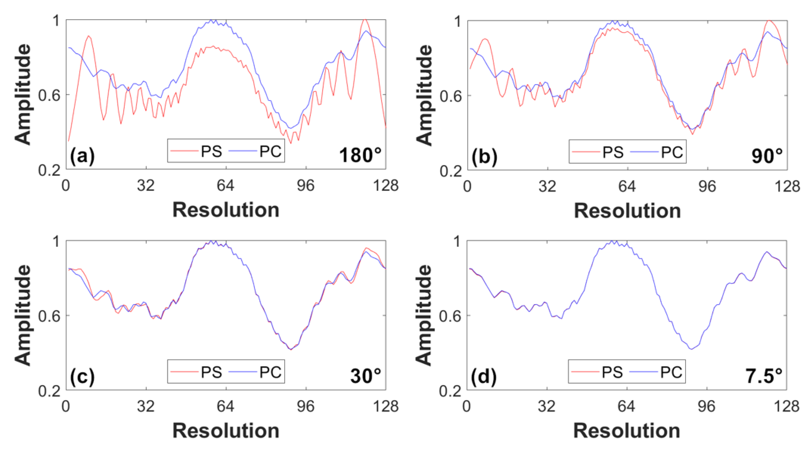
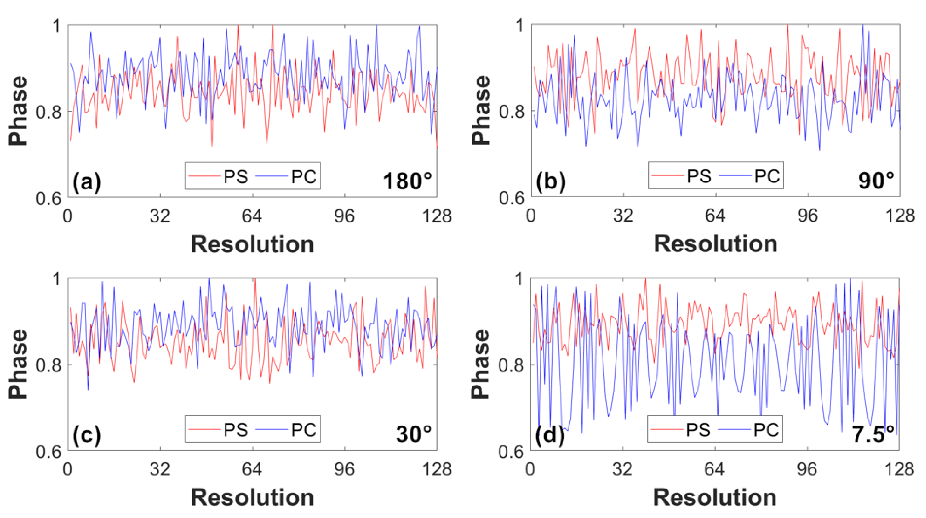
The SCGH can be reconstructed in two different ways: PS and PC method. One is used to verify the correctness of the newly proposed PC method, while the other is a fast calculation method to reconstruct the SCGH which can be applied to optical reconstruction experiments of SCGH.

2.5.1. Reconstruction by PS Method

According to the spherical wave diffraction theory, an arbitrary point E ( x a , y b , z 1 ) on the object plane can be expressed by the superposition of the diffraction distributions of all points on the SCGH. The schematics are as shown in Figure 1c,d. The reconstruction process by PS method can therefore be given by
E ( x a , y b , z 1 ) = p = 1 P q = 1 Q 1 L p q G ( x p , y q , z s ) exp ( j k L p q ) , L p q = ( x a x p ) 2 + ( y b y q ) 2 + ( z 1 z s ) 2 ,
where ( x a , y b , z 1 ) and ( x p , y q , z s ) are discrete coordinates of arbitrary points E and G on the object plane and SCGH. P × Q is the resolution of SCGH.
Pay attention that the rule of nonuniform sampling mentioned in Section 2.3 should be obeyed in this reconstruction process to keep accordance with the procedure of SCGH generation.

2.5.2. Reconstruction by PC Method

Apart from the original PS method, the proposed PC method can also be adopted in the reconstruction of SCGH, which is the inverse process of the PC generation method. It can be calculated as follows,
S t e p 1 : u w ( x w , y w , z 2 ) = u h · exp ( j k d P C ) , S t e p 2 : u o ( x o , y o , z 1 ) = F 1 { F { u w ( x w , y w , z 2 ) } · exp [ j 2 π λ z 1 ( λ f x w ) 2 ( λ f y w ) 2 ] } .
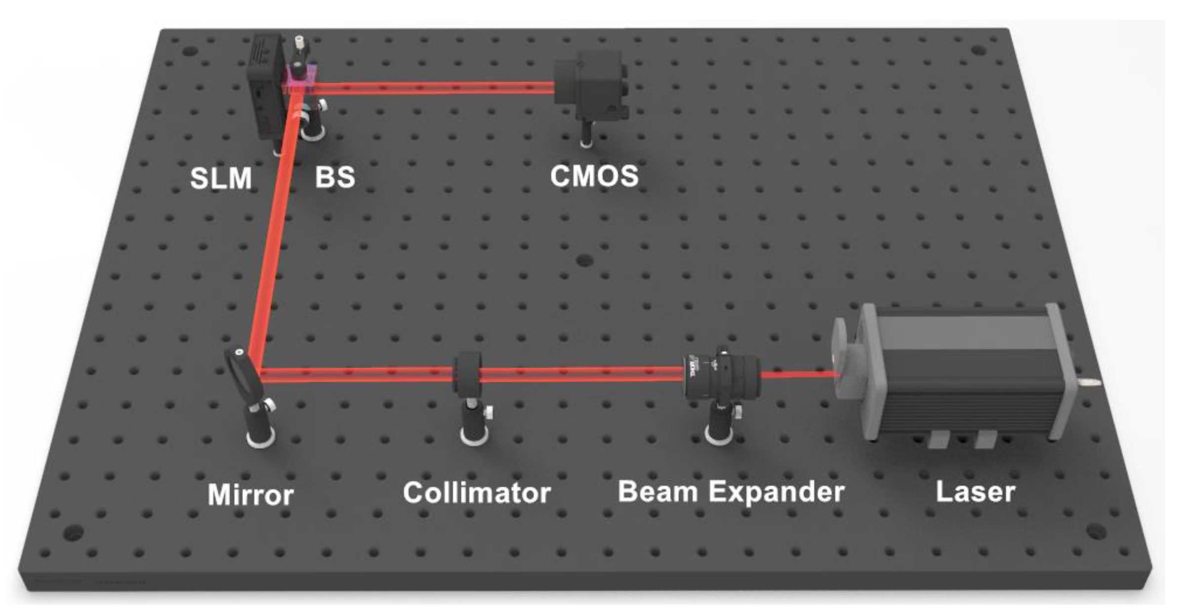
As the SLM with curved surface is difficult to realize so far, an alternative approach to implement optical experiments is to compensate the phase difference between SCGH and planar SLM by the step 1 of the reconstruction by PC method before loading on the SLM. After the compensation step, the complex amplitude of WRP can be encoded into a phase-only hologram and loaded on the planar SLM for reconstruction.

3. Simulations and Experiments

3.1. Numerical Simulations

Three sets of comparative numerical simulations are carried out to illustrate the correctness of PS method. The wavelength λ is 635 nm in visible range, and the physical side length of object plane L o is 5.3 mm. The horizontal and vertical flare angles of WRP to the center of SCGH θ and φ are used to represent the curvature of SCGH segment as the physical side length of object plane is fixed, and θ = φ for simplicity. The original object images used in numerical simulations and optical experiments are shown in Figure 3. The peak signal-to-noise ratio (PSNR) and the structural similarity index (SSIM) are used as quality measurements during simulations [22]. Considering the huge amount of time consumed by the PS method, the maximum resolution of the object images used in simulations is 256 × 256 .

3.1.1. Verification of PC Method

The purpose of the first set of simulations is to prove the correctness of the proposed PC method by generating the SCGHs by PC or PS method and reconstructing them by PS or PC, respectively. The object planes are square images with 128 × 128 pixels. The flare angle of WRP is 7.5 , and the distance d between WRP and SCGH is 345.5 mm. The results including PSNR(dB) are shown in Figure 4.
The relatively high values of PSNR verify the bidirectionality of the proposed PC method, which means it can be used to calculate both diffracted and reconstructed optical field between a plane and a sphere. There is almost no difference visually between the results reconstructed by PC and PS methods, and the actual difference between them is extremely small, according to the little disparity of PSNR between Figure 4b,d,f and Figure 4h,j,l. However, there is no denying that the difference does exist when the PS and PC methods are used separately in synthesis and reconstruction. The PS method is regarded as accurate in order to further discuss this issue. When taking it in the generation process as shown in Figure 4g–l, the diffracted optical fields from the object plane are recorded precisely, while the images are approximate reconstructed when the other method is used during reconstruction; whereas, the images in Figure 4a–f are reconstructed using the opposite method. Due to the asymmetry of these two processes, the error of the PC methods introduced in generation and reconstruction cannot be eliminated.
In the second set of simulation, object planes of different resolution are compared by PS and PC methods. The reconstructed results with different resolution are shown in Figure 5 and Table 1. In addition to PSNR, the SSIM is used simultaneously as a quality measurement in this simulation. With the resolution of the object plane increasing, the PSNR and SSIM of the results reconstructed by both methods decline because each pixel introduces error in the process of applying the PC method. However, the clearly reconstructed images in Figure 5 prove that the proposed method works well with various of resolution.
According to the analysis in Section 2.4, the error introduced by the PC method will be increasing as the curvature of SCGH increases, and the PSNR of the reconstruction results should decrease dramatically. In order to verify this point of view, we conducted the third set of simulation comparing the quality of reconstructed images of SCGHs with different curvatures. In this experiment, we tested the flare angles of WRP ranged from 180 to 7.5 as they determine different curvatures of the SCGH segments. For simplicity, the graphic results present only four main angles, and the rest refer to the PSNR curve, as shown in Figure 6 (considering the computation time, the resolution of the object plane is set to 64 × 64 ).
According to the results of graphs and PSNR, the quality of the reconstructed image is better with the decreasing on the flare angle of WRP, which means that the error of PC method is greater with wider range of curvature of SCGH. Furthermore, the error reaches the maximum when the flare angle is 180 . This result coincides with our analysis above. However, for SCGHs with relatively large curvatures, the images are still of good quality despite degradation. It proves the feasibility of the proposed PC method used in SCGHs with wide range of curvatures.

3.1.2. Computing Speed Comparison

To illustrate the acceleration performance of the proposed PC method to generate the SCGH, we compared the computation time of our method and the traditional PS method, as shown in Table 2 and Figure 7. The speedup ratio r s is defined as shown in Equation (11) to measure the acceleration performance of our proposed method,
r s = t P S / t P C ,
where t P S and t P C denote the computation time of PS and PC method. All the simulations are calculated by Intel (R) Core (TM) i5-7200U CPU @ 2.50 GHz 2.71 GHz.
For an object plane of the same resolution and corresponding flare angle of WRP, the computation speed of our PC method is further accelerated compared with that of the traditional PS method. Moreover, for the object planes with the same resolutions, the computation time is nearly consistent when calculated by the same method. When the resolution increases, the computation time of the PS method increases dramatically compared with our PC method. It turns out that our PC method has good scalability and it greatly speeds up the computation of the diffraction process between a plane and a sphere.
The comparison of calculation time for the PS [17], convolution [17], and proposed PC methods is shown in Table 3. For the traditional PS method, the calculation is at an unacceptable low speed even though fewer sampling points can be used, and for the convolution method, a long period of time is required because of the staggering sampling rate required in the concentric spherical model in visible range. In contrast, the SCGH can be perfectly synthesized by the proposed PC method at an obviously high speed with a small number of sampling points.

3.1.3. Error Analysis of PC Method

Based on the error analysis in Section 2.4, we measured the error in both amplitude and phase between the diffraction distributions calculated by PS and PC methods. For each result, we accumulated and normalized the elements of the amplitude and phase matrix in columns as shown in Equation (12):
y a = q = 1 Q a b s ( u h ) / m a x ( q = 1 Q a b s ( u h ) ) , y p = q = 1 Q a n g l e ( u h ) / m a x ( q = 1 Q a n g l e ( u h ) ) ,
where y a and y p denote, respectively, the accumulated and normalized amplitude and phase of the diffraction field; u h is the diffraction distribution; Q is the row number of the amplitude and phase matrix; and a b s ( · ) and a n g l e ( · ) represent the modulo and phase angle operator, respectively. Here, we take the object plane resolution of 128 × 128 as an example. The error in amplitude and phase between the two diffraction results is visualized by graphs as shown in Figure 8 and Figure 9.
With the decreasing of the curvature of SCGH, the red line and the blue line in Figure 8 tend to coincide with each other, which means the amplitude error between the PS and PC method is reducing, and it coincides well with the theoretical analysis in Section 2.4. Moreover, the error reaches the maximum when the flare angle is 180 as shown in Figure 8a and Figure 9a. However, the phase curves in Figure 9 are relatively inconsistent. As the distance between WRP and SCGH is much greater than the wavelength, the phase is much more sensitive to the subtle difference of this distance that changes with the flare angle of WRP. In general, the error of PC method is small enough to calculate the diffraction distribution between a plane and a sphere correctly.

3.2. Optical Experiments

Optical experiments are carried out according to Section 2.5.2 in order to further certify the practicality of our proposed PC method. The schematic of optical experimental set-up is shown in Figure 10. The 671 nm laser is expanded and collimated by the beam expander and collimating lens. The phase-only holograms are loaded on the flat reflection-type phase-only LCOS-SLM with a beam splitter (BS) close to it. The resolution and the sampling intervals of the SLM is 1920 × 1080 and 8 μ m, respectively. The reconstructed images are recorded by the CMOS camera which is 200 mm away from the SLM.
Three pictures including U S A F , c a m e r a m a n and p e p p e r s are used for optical experiments. Moreover, the optical reconstructed results are shown in Figure 11 where SCGHs with corresponding flare angles of 90 and 7.5 are shown as representatives. The SCGHs can be correctly reconstructed as shown in Figure 11a–f, which further validates the feasibility of the proposed method. However, the reconstructed images are with obvious speckle noise since one phase-only hologram is used for each reconstruction. Therefore, the time division multiplexing method is used as optimization to suppress the speckle noise and improve the image quality as shown in Figure 11g–l [23]. All the results are in accordance with our theoretical analysis.

4. Conclusions

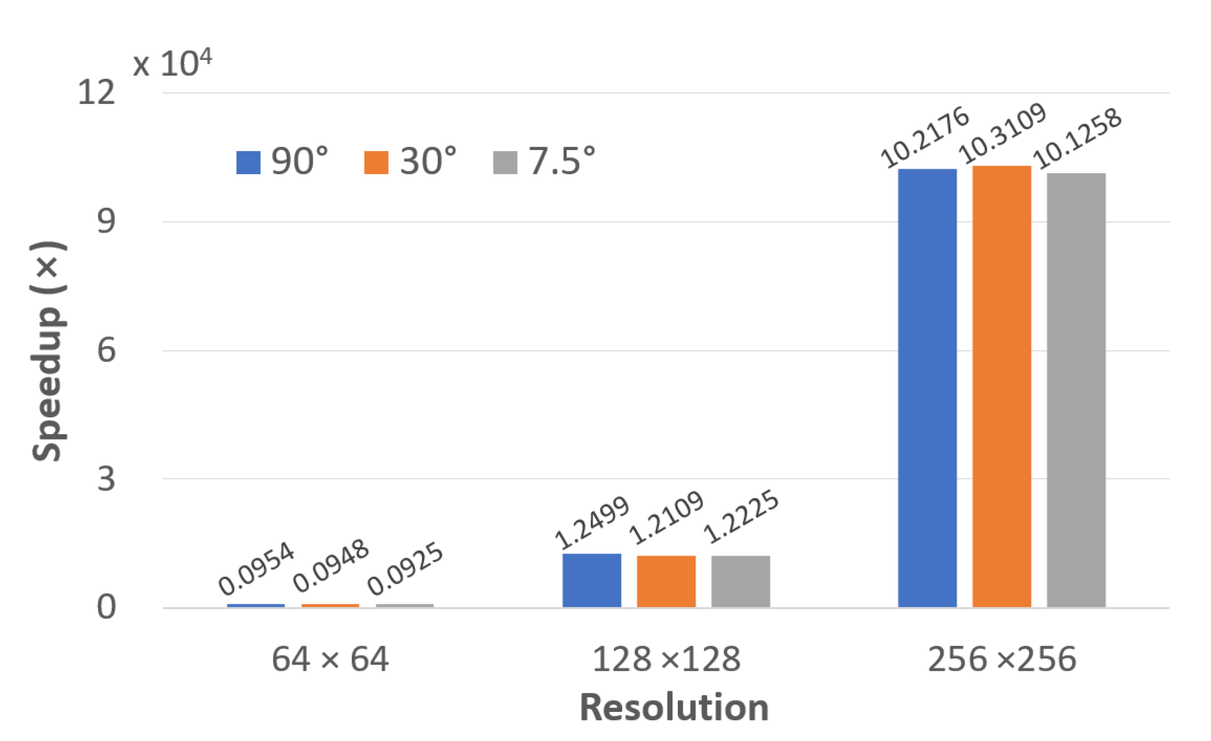
In this paper, a fast diffraction calculation between plane and sphere is proposed for SCGH based on PC method. After recording the wavefront distribution in WRP from the object plane, the phase difference between WRP and SCGH introduced by the optical path difference is approximately compensated point-to-point to synthesis the ultimate SCGH, during which the SCGH is nonuniformly sampled, and the pixel resolution required is greatly decreased. The feasibility, the approximation error and the acceleration performance of the proposed method are verified and analyzed according to the numerical simulations. Compared with the original PS method, the computing speed is significantly accelerated with good scalability. As the object-plane resolution increases, the speedup between PS and PC method is improved significantly from 954 ( 64 × 64 , 90 ) to 102,176 ( 256 × 256 , 90 ). Moreover, the sampling points are significantly reduced by 10 4 times compared with the convolution and spherical spectrum method. Furthermore, in spite of the approximation of our proposed PC method, the reconstructed images are of good quality regardless of the increase on the curvature of SCGHs or the resolution of the object planes. Therefore, the calculation speed problem of the propagation model between plane and sphere has been solved firstly as far as we know. Meaningfully, it is possible for the practical applications of SCGH as the visible range of light wavelengths can be adopted to synthesize and reconstruct SCGHs. Moreover, an alternative approach using the proposed PC method to implement optical experiments of SCGH is provided to address the current issue of realizing holographic display with curved surfaces. In the future, it is expected to achieve an omnidirectional spherical holographic display by stitching SCGH segments; all these endow the spherical holography with more practical prospects.

Author Contributions

Conceptualization, R.Y. and J.W.; methodology, R.Y.; software, R.Y. and Y.W.; validation, R.Y. and J.W.; formal analysis, B.L. and Y.L.; investigation, J.W.; resources, R.Y.; data curation, R.Y.; writing—original draft preparation, R.Y.; writing—review and editing, J.W., C.C., B.L., Y.L., N.C. and B.J.J.; visualization, R.Y., C.C. and Y.W.; supervision, J.W.; project administration, J.W.; funding acquisition, J.W. All authors have read and agreed to the published version of the manuscript.

Funding

This research was funded by the National Natural Science Foundation of China (NSFC) (U1933132) and the Chengdu Science and Technology Program (2019-GH02-00070-HZ).

Conflicts of Interest

The authors declare no conflict of interest.

References

  1. Cao, H.; Kim, E. Full-scale one-dimensional NLUT method for accelerated generation of holographic videos with the least memory capacity. Opt. Express 2019, 27, 12673–12691. [Google Scholar] [CrossRef] [PubMed]
  2. Zhao, Y.; Kwon, K.; Erdenebat, M.; Jeon, S.; Piao, M.; Kim, N. Implementation of full-color holographic system using non-uniformly sampled 2D images and compressed point cloud gridding. Opt. Express 2019, 27, 29746–29758. [Google Scholar] [CrossRef] [PubMed]
  3. Chen, N.; Lam, E.; Poon, T.; Lee, B. Sectional hologram reconstruction through complex deconvolution. Opt. Lasers Eng. 2020, 127, 105945. [Google Scholar] [CrossRef]
  4. Teng, D.; Liu, L.; Zhang, Y.; Pang, Z.; Chang, S.; Zhang, J.; Wang, B. Spatiotemporal multiplexing for holographic display with multiple planar aligned spatial-light-modulators. Opt. Express 2014, 22, 15791–15803. [Google Scholar] [CrossRef]
  5. Lohmann, A.; Paris, D. Binary Fraunhofer Holograms, Generated by Computer. Appl. Opt. 1967, 6, 1739–1748. [Google Scholar] [CrossRef]
  6. Rosen, J. Computer-generated holograms of images reconstructed on curved surfaces. Appl. Opt. 1999, 38, 6136–6140. [Google Scholar] [CrossRef] [Green Version]
  7. Park, J.; Kim, M.; Baasantseren, G.; Kim, N. Fresnel and Fourier hologram generation using orthographic projection images. Opt. Express 2009, 17, 6320–6334. [Google Scholar] [CrossRef]
  8. Jackin, B.; Yatagai, T. Fast calculation method for computer-generated cylindrical hologram based on wave propagation in spectral domain. Opt. Express 2010, 18, 25546–25555. [Google Scholar] [CrossRef]
  9. Cao, H.; Lin, S.; Kim, E. Accelerated generation of holographic videos of 3-D objects in rotational motion using a curved hologram-based rotational-motion compensation method. Opt. Express 2018, 26, 21279–21300. [Google Scholar] [CrossRef]
  10. Wang, J.; Wang, Q.; Hu, Y. Unified and accurate diffraction calculation between two concentric cylindrical surfaces. J. Opt. Soc. Am. A 2018, 35, A45–A52. [Google Scholar] [CrossRef]
  11. Yamaguchi, T.; Fujii, T.; Yoshikawa, H. Fast calculation method for computer-generated cylindrical holograms. Appl. Opt. 2008, 47, D63–D70. [Google Scholar] [CrossRef] [PubMed]
  12. Sando, Y.; Itoh, M.; Yatagai, T. Fast calculation method for cylindrical computer-generated holograms. Opt. Express 2005, 13, 1418–1423. [Google Scholar] [CrossRef] [PubMed]
  13. Sando, Y.; Barada, D.; Jackin, B.; Yatagai, T. Fast calculation method for computer-generated cylindrical holograms based on the three-dimensional Fourier spectrum. Opt. Lett. 2013, 38, 5172–5175. [Google Scholar] [CrossRef] [PubMed]
  14. Sando, Y.; Barada, D.; Jackin, B.; Yatagai, T. Bessel function expansion to reduce the calculation time and memory usage for cylindrical computer-generated holograms. Appl. Opt. 2017, 56, 5775–5780. [Google Scholar] [CrossRef]
  15. Zhao, Y.; Piao, M.; Li, G.; Kim, N. Fast calculation method of computer-generated cylindrical hologram using wave-front recording surface. Opt. Lett. 2015, 40, 3017–3020. [Google Scholar] [CrossRef]
  16. Li, G.; Phan, A.; Kim, N.; Park, J. Synthesis of computer-generated spherical hologram of real object with 360° field of view using a depth camera. Appl. Opt. 2013, 52, 3567–3575. [Google Scholar] [CrossRef]
  17. Tachiki, M.; Sando, Y.; Itoh, M.; Yatagai, T. Fast calculation method for spherical computer-generated holograms. Appl. Opt. 2006, 45, 3527–3533. [Google Scholar] [CrossRef]
  18. Jackin, B.; Yatagai, T. Fast calculation of spherical computer generated hologram using spherical wave spectrum method. Opt. Express 2013, 21, 935–948. [Google Scholar] [CrossRef]
  19. Li, G.; Hong, K.; Yeom, J.; Chen, N.; Park, J.; Kim, N.; Lee, B. Acceleration method for computer generated spherical hologram calculation of real objects using graphics processing unit. Chin. Opt. Lett. 2014, 12, 060016. [Google Scholar]
  20. Sando, Y.; Barada, D.; Jackin, B.; Yatagai, T. Spherical-harmonic-transform-based fast calculation algorithm for spherical computer-generated hologram considering occlusion culling. Appl. Opt. 2018, 57, 6781–6787. [Google Scholar] [CrossRef]
  21. Cao, H.; Kim, E. Faster generation of holographic videos of objects moving in space using a spherical hologram-based 3-D rotational motion compensation scheme. Opt. Express 2019, 27, 29139–29157. [Google Scholar] [CrossRef] [PubMed]
  22. Alnajjar, Y.; Soong, C. Comparison of Image Quality Assessment: PSNR, HVS, SSIM, UIQI. Int. J. Sci. Eng. Res. 2012, 3, 1–5. [Google Scholar]
  23. Xin, L.; Xiao, D.; Wang, Q. Method to suppress speckle noise using time multiplexing in phase-only holographic display. J. Soc. Inf. Disp. 2019, 28, 641–647. [Google Scholar] [CrossRef]
Figure 1. Panels (a,b) represent for the propagation model between plane and sphere; panels (c,d) are schematics of spherical computer-generated hologram (SCGH) generation by phase compensation (PC) method.
Applsci 10 05784 g001
Figure 2. Schematic diagram of nonuniform sampling. Panel (a) is the 3D model of sampling, where N is the vertical projection point of M on SCGH; panel (b) is the top view of arc A B on the SCGH ( R is the projection on the x-z plane of the radius R of SCGH).
Applsci 10 05784 g002
Figure 3. Original object images of the simulations (ac) and experiments (df).
Applsci 10 05784 g003
Figure 4. Verification of the proposed method. Panels (a,c,e) are diffracted field by PC method; panels (b,d,f) are reconstructed field by point source (PS) method; panels (g,i,k) are diffracted field by PS method; panels (h,j,l) are reconstructed field by PC method.
Applsci 10 05784 g004
Figure 5. Reconstruction results of object plane with different resolution. Panels (a,c,e) are generated by PC and reconstructed by PS method; panels (b,d,f) are generated by PS and reconstructed by PC method.
Applsci 10 05784 g005
Figure 6. PSNR curve of different flare angles of wavefront recording plane (WRP).
Applsci 10 05784 g006
Figure 7. Speedup variation with the change in resolution and flare angle.
Applsci 10 05784 g007
Figure 8. Error of the diffraction results between PS (red line) and PC (blue line) method in amplitude with different flare angles of WRP. (a) 180 , (b) 90 , (c) 30 and (d) 7.5 .
Applsci 10 05784 g008
Figure 9. Error of the diffraction results between PS (red line) and PC (blue line) method in phase with different flare angles of WRP. (a) 180 , (b) 90 , (c) 30 and (d) 7.5 .
Applsci 10 05784 g009
Figure 10. Schematic of optical experimental set-up.
Applsci 10 05784 g010
Figure 11. Optical reconstructed results of the proposed PC method. (af) and (gl) are results without and with optimization, respectively.
Applsci 10 05784 g011
Table 1. Propagation distance d, peak signal-to-noise ratio (PSNR) and structural similarity index (SSIM) of PS and PC methods for object planes with different resolution.
RESOLUTIONd (mm)RECONSTRUCTION METHODPSNR (dB)SSIM
64 × 64 691.0PS59.660.999
PC57.700.998
128 × 128 345.5PS55.080.995
PC56.580.997
256 × 256 172.8PS46.050.983
PC20.670.923
Table 2. Computation time comparison of PC and PS method with different resolution and flare angles of WRP.
RESOLUTIONFLARE ANGLEPCPSSPEEDUP
64 × 64 90 0.012 s11.446 s953.83
30 0.012 s11.376 s948.00
30 0.012 s11.101 s925.08
128 × 128 90 0.015 s187.492 s12499.47
30 0.015 s181.635 s12109.00
30 0.015 s183.380 s12225.33
256 × 256 90 0.030 s3065.274 s102175.80
30 0.029 s2990.167 s103109.21
7.5 0.029 s2936.473 s101257.69
Table 3. Comparison of sampling points and calculation time required using different calculation method in visible range.
METHODWAVELENGTHSAMPLING POINTSTIME
PS [17]635 nm 256 × 256 2997.305 s
Convolution [17]200,000 × 200,0003454.285 s
Proposed PC 256 × 256 0.029 s

