A Low-Autogenous-Shrinkage Alkali-Activated Slag and Fly Ash Concrete


1
Department of Materials, Mechanics, Management & Design, Faculty of Civil Engineering and Geoscience, Delft University of Technology, 2628 CN Delft, The Netherlands
2
National Engineering Laboratory for Coal-Fired Pollutants Emission Reduction, Shandong University, Jinan 250061, China
3
School of Materials Science and Engineering, South China University of Technology, Guangzhou 510640, China
4
Magnel Laboratory for Concrete Research, Department of Structural Engineering, Ghent University, 9052 Ghent, Belgium
*
Author to whom correspondence should be addressed.
Appl. Sci. 2020, 10(17), 6092; https://0-doi-org.brum.beds.ac.uk/10.3390/app10176092
Submission received: 17 August 2020
/
Revised: 30 August 2020
/
Accepted: 31 August 2020
/
Published: 2 September 2020
(This article belongs to the Special Issue High-Performance Eco-Efficient Concrete)
Abstract
:Alkali-activated slag and fly ash (AASF) materials are emerging as promising alternatives to conventional Portland cement. Despite the superior mechanical properties of AASF materials, they are known to show large autogenous shrinkage, which hinders the wide application of these eco-friendly materials in infrastructure. To mitigate the autogenous shrinkage of AASF, two innovative autogenous-shrinkage-mitigating admixtures, superabsorbent polymers (SAPs) and metakaolin (MK), are applied in this study. The results show that the incorporation of SAPs and MK significantly mitigates autogenous shrinkage and cracking potential of AASF paste and concrete. Moreover, the AASF concrete with SAPs and MK shows enhanced workability and tensile strength-to-compressive strength ratios. These results indicate that SAPs and MK are promising admixtures to make AASF concrete a high-performance alternative to Portland cement concrete in structural engineering.
1. Introduction
An important way to reduce the CO2 emissions from the construction sector is to use “greener” alternative binders to ordinary Portland cement (OPC). Alkali-activated materials (AAMs), or so-called geopolymers, which can be made of industrial by-products, have been reported to entail much lower CO2 emission and embodied energy than OPC systems [1].
Blast-furnace slag (indicated as “slag” hereafter) and fly ash, as by-products from steelmaking and coal-fired electricity plants, respectively, are the two most commonly utilized precursors to produce AAMs. The literature has illustrated that alkali-activated slag and fly ash (AASF) shows superior strength, excellent durability and good fire resistance compared to OPC systems [2,3,4]. However, a wider application of this material has not been reached yet, partly due to the large autogenous shrinkage and the potential risk of cracking of this material, especially when NaOH and Na2SiO3 are used as activators [5,6].
A number of studies have been conducted to reduce the shrinkage of AASF. However, it has been found that the shrinkage-reducing agents and expansive additives that are widely adopted in OPC may be ineffective or cause side effects (e.g., strength loss) in AAMs due to the differences in microstructures and chemical environments between AAMs and OPC [7,8]. Elevated temperature curing can mitigate the shrinkage of AASF [9], but this strategy has high requirements on the curing equipment and can accelerate the setting of AASF, which is already more rapid than usually needed. Feasible strategies to mitigate the autogenous shrinkage of AASF are desired to widen the commercial acceptance of this material.
The results of previous studies [10,11,12,13] indicate that internal curing and incorporation of a small amount of metakaolin (MK) are helpful to reduce the autogenous shrinkage of alkali-activated slag (AAS) and AASF. However, both of these two strategies have their limitations. Internal curing can significantly mitigate the autogenous shrinkage caused by self-desiccation, but on the first day when autogenous shrinkage rapidly develops, the effect of internal curing is quite limited due to the possible involvement of other shrinkage mechanisms [13]. By contrast, the incorporation of MK can effectively mitigate the early-age autogenous shrinkage of AAS and AASF by reducing the high reaction rate in the acceleration period and coarsening the gel pores [10]. However, the effect of MK on later-age autogenous shrinkage is not evident. These results indicate that these two admixtures might be a good complement to each other to further lower the autogenous shrinkage of AAMs. However, the combined effect of them on the autogenous shrinkage and cracking properties of AASF systems have not been studied yet.
In this study, superabsorbent polymers (SAPs) and MK are applied to reduce the autogenous shrinkage of AASF. Experiments are conducted at both paste and concrete scales. The cracking potential of paste and concrete is evaluated by the ring test and Temperature Stress Testing Machine (TSTM), respectively. The workability and the mechanical properties of the concrete are also investigated. Eventually, with the addition of SAPs and MK, a high-performance eco-efficient alkali-activated concrete is produced.
2. Materials and Methods
2.1. Raw Materials
The main precursors used in this study were slag and Class F fly ash. The material parameters of these two precursors are shown in Table 1 and Table 2.
Bulk-polymerized SAPs with particle sizes up to about 200 µm in the dry state were used. The SAPs were a cross-linked copolymer based on acrylamide and acrylate. The composition and physical properties of MK are also shown in Table 1 and Table 2, respectively. It should be noted that part of the high percentage of silica content in MK was due to the presence of quartz (43% in weight), which remains inert during the reaction process [14]. No admixture besides SAPs and MK was used.
Pellets of NaOH, deionized water and commercial water glass solution were used to synthesize the alkaline activator. For 1000 g of precursor, an activator containing 384 g of water, 1.146 mol of SiO2 and 0.76 mol of Na2O was applied.
2.2. Mixtures
The mixture design of the plain AASF paste and AASF paste with SAPs and/or MK is shown in Table 3.
The dosage of SAPs was designed based on the absorption capacity of the SAPs (20 g/g activator [11]) and the chemical shrinkage of AASF paste. The ultimate chemical shrinkage of AASF paste was determined by taking the chemical shrinkage measured by dilatometry untill the age of 28 days [15,16], which was 0.026 mL/g. Taking also into account the density of the activator as well, 1.23 g/cm3, the extra liquid provided by the SAPs should be 0.032 g per gram of binder. Therefore, the adding amount of 0.16 wt. % SAP was applied for the internal curing of AASF.
According to the results from previous studies [10,17], 5 wt. % of MK in the binder can already show a significant mitigating effect on the autogenous shrinkage of AASF paste. Higher amounts of MK may lead to considerable strength loss in the matrix. Therefore, the dosage of MK in this study was chosen as 5 wt. % of the binder as a substitution for 10 wt. % of slag.
Based on the results at the paste scale (details will be given in Section 3.1 and Section 3.2), two mixtures, AASF and AASFICMK, were chosen for experiments at the concrete scale. The mixture proportions of the concrete mixtures are shown in Table 4.
2.3. Experimental Methods
2.3.1. Autogenous Shrinkage of Paste
2.3.2. Cracking Potential of Paste
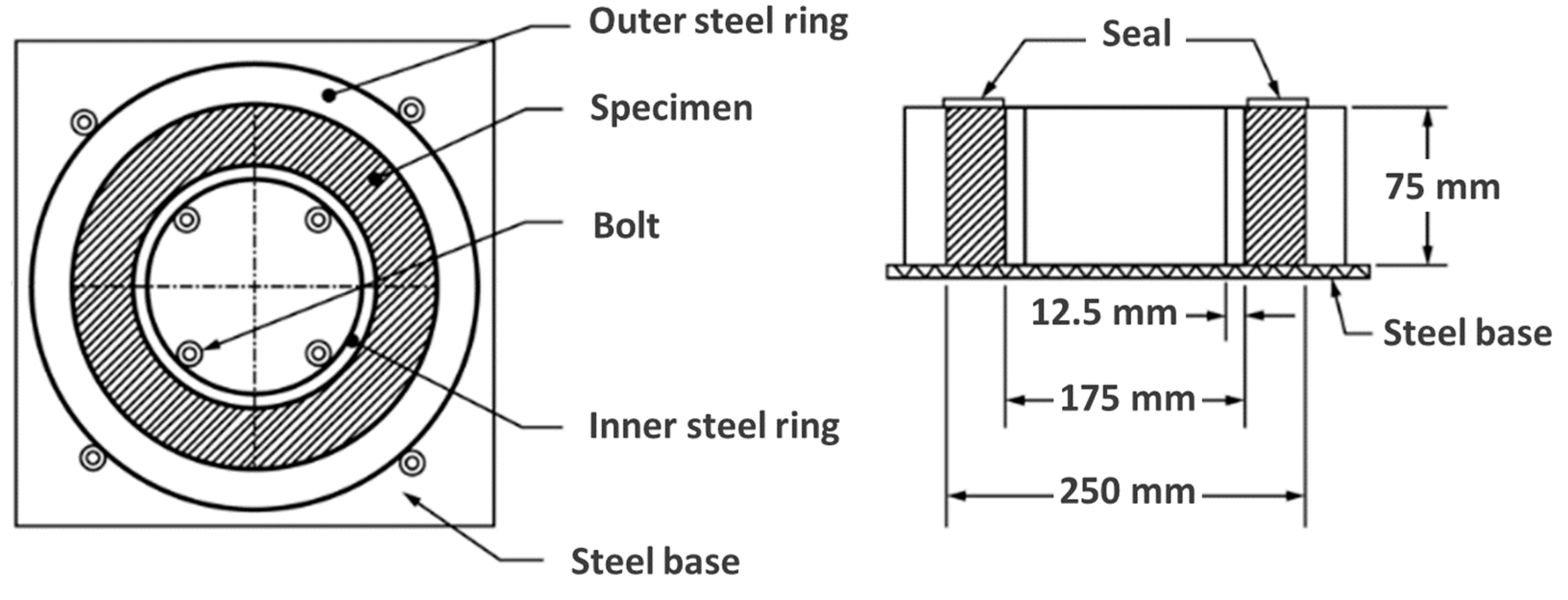
The cracking potential of the paste induced by restrained autogenous shrinkage was indicated by the dual ring test [20,21]. The geometry of the rings is shown in Figure 1. The strain gauges attached to the inner surface of the inner steel ring started to record the strains of the inner ring when the paste was cast in between the two steel rings. The paste ring was sealed by aluminium foil fixed with asphalt tape during the test to avoid moisture loss. The apparatus was put in a temperature-controlled room with the temperature fixed at 20 °C.
The maximal stress in the paste was calculated according to Equation (1) based on the strain and dimensions of the rings [23].
where is the maximum stress in the paste ring; is the measured strain of the inner steel ring; is the elastic modulus of the ring; , and are the inter radius of the inner steel ring (75 mm), the inner radius of the paste (87.5 mm) and its outer radius (125 mm), respectively.
2.3.3. Workability of Concrete
The workability of AASFICMK concrete was measured. The slump was measured according to NEN 12350 [24]. The largest diameter of the flow spread of the concrete and the diameter of the spread at right angles to it were measured immediately after the cone was lifted up. The setting time of AASFICMK concrete was determined by the Vicat method [25] on the corresponding paste.
2.3.4. Autogenous Shrinkage of Concrete
The autogenous shrinkage of the concrete was measured with an Autogenous Deformation Testing Machine (ADTM) [26]. The prismatic mold for the concrete was made of thin steel plates and external insulating materials. The size of the mold is 1000 × 150 × 100 mm3 (see the top left corner of Figure 2). The mold was connected with cryostats by a series of circulation canals located between the plates and the insulating material.
The length change of the concrete was measured with two external quartz rods located next to the side mold. Linear Variable Differential Transformers (LVDTs) were installed at both ends of the rods. The LVDTs measured the movement of the steel bars, which were cast in the concrete. The distance between the two embedded steel bars was 750 mm. The measurement of the deformation of AASF and AASFICMK concrete started at 11h and 12 h after casting, respectively, when the concrete was stiff enough to hold the measuring bars and the LVDTs that were connected with them. Attention was paid to the sealing of the molds in order to avoid moisture loss to the environment.
2.3.5. Cracking Potential of Concrete
The cracking initiation in the concrete was monitored by a TSTM. The TSTM was equipped with a horizontal steel frame in which compressive and tensile force could be applied on the concrete specimen. A temperature-controlled mold was used for the concrete casting in order to obtain any prescribed thermal condition. The mold was similar to the ADTM mold described in Section 2.3.4. The whole specimen was of a dog-bone shape and the testing area of interest was of a prismatic shape (1000 × 150 × 100 mm3), see the bottom left corner of Figure 2. The deformation of the concrete was kept at zero (nominally, in reality within ±1 µm range) so that a full restraint condition could be reached. When the total deformation of the concrete went beyond the threshold, a load was applied to pull or push the concrete back to the original position. The load was recorded with the load cell with a loading capacity of 100 kN and a resolution of 0.049 kN. A sudden drop in the load to around zero indicated the occurrence of cracking in the concrete.
2.3.6. Strength of Concrete
Concrete cubes (150 × 150 × 150 mm3) for the compressive and splitting strength tests were cast and cured in sealed and temperature-controlled steel molds (see the top middle of Figure 2). The moulds were connected with cryostats by parallel circulation tubes and the upper surface was sealed by plastic film.
The compressive strength and splitting strength of the concrete were measured according to NEN-EN 12390 [27]. The measurements were conducted at the age of 1, 3, 7 and 28 days and the day when the concrete beam in the TSTM cracked. One cube was tested for compressive strength and two for splitting strength.
To keep consistency of the materials, the concrete samples for strength, autogenous shrinkage and cracking potential measurements were from the same batch of casting. All the samples were cured in a sealed condition. The whole set-up, including the TSTM, ADTM, cubes and controlling systems is schematically shown in Figure 2. Various thermocouples were used to monitor the temperatures of the samples. To minimize the influence of thermal deformation on the autogenous shrinkage, the temperatures of the middle parts of the specimen, i.e., T3 for the TSTM, T7 for the ADTM, and T9 for the cubes, were controlled at 20 °C.
3. Results and Discussion
3.1. Autogenous Shrinkage of Paste
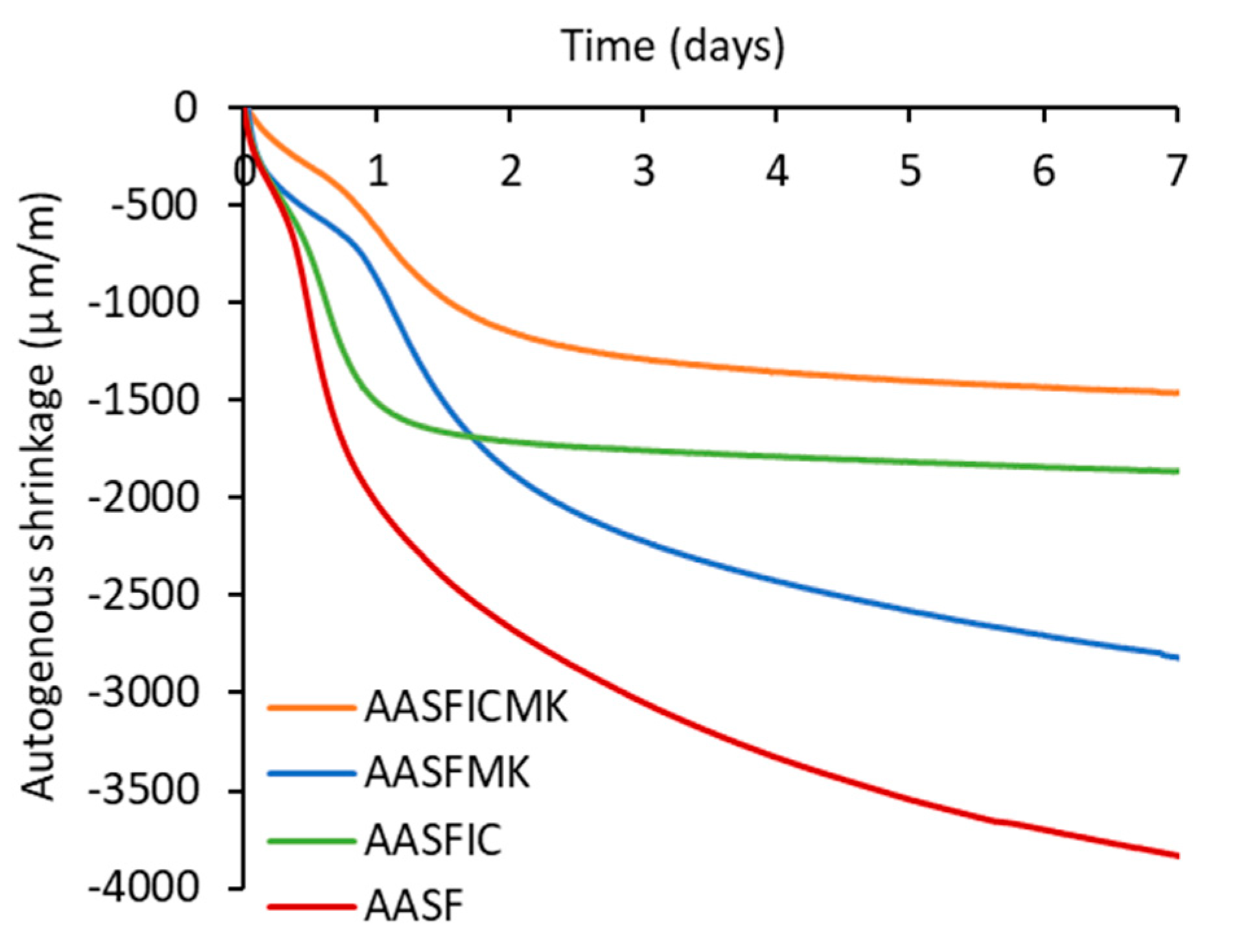
The autogenous shrinkage curves of the paste mixtures are shown in Figure 3. The autogenous shrinkage of AASF paste reached more than 2000 µm/m at 1 day and around 4000 µm/m at the age of 7 days. This magnitude is higher than the autogenous shrinkage of common OPC-based systems irrespective of the presence of supplementary materials [29,30]. The shrinkage mechanism was discussed in a previous study [19]. It can be seen from Figure 3 that both the additions of SAPs and MK resulted in lower autogenous shrinkage of AASF paste. In particular, the addition of SAPs greatly mitigate the autogenous shrinkage of AASF paste after the first day. By contrast, MK was more effective on the first day; afterward, the effect of MK became less evident.
When SAPs and MK were added together into AASF, the autogenous shrinkage of the paste was the lowest among all the four mixtures in the whole week. The mitigating effect of the combination of SAPs and MK was more evident than when they were applied individually. Both the early-age and later-age autogenous shrinkage were significantly mitigated compared to those of the plain AASF paste. For example, the 1-day and 7-day autogenous shrinkage of AASFICMK paste was only 30% and 40% of that of AASF paste, respectively. This result indicates that SAPs and MK complement each other in mitigating the autogenous shrinkage of AASF.
3.2. Cracking Potential of Paste
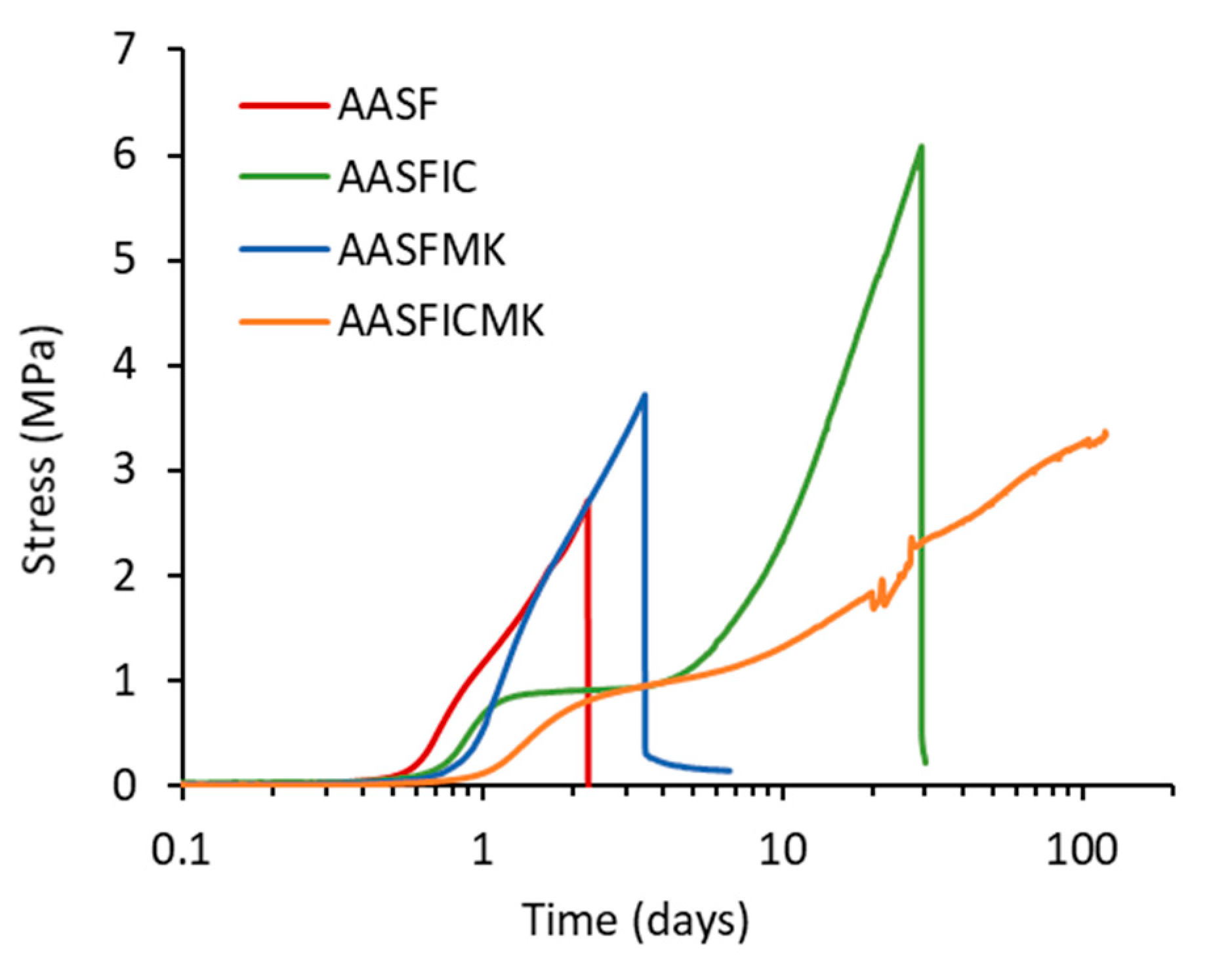
It should be noted that low autogenous shrinkage does not necessarily mean low cracking potential. If the mitigating effect on the autogenous shrinkage is at the cost of dramatic loss in strength loss, the material may be subject to higher cracking risk [31]. To investigate the effect of SAPs and MK on the cracking potential of the paste, the ring test was used to measure the stress in the paste mixtures under a restrained condition. The results are shown in Figure 4. The sudden drop in the stress to around zero indicated the occurrence of cracking.
Figure 4 shows that the plain AASF paste cracked on the third day after casting when the internal stress reached around 2.7 MPa. Substituting 10 wt. % slag by MK prolonged the cracking time by about 1 day and the paste broke at a stress of 3.7 MPa. The cracking potentials of AASF and AASFMK pastes were both “high” according to ASTM C1581 [22]. With internal curing by SAPs, the paste did not crack until 29 days of curing when the stress reached 6 MPa. Since the cracking time of AASFIC was close to 28 days, and the stress rate at the cracking time was 0.14 MPa/day, the cracking potential of AASFIC could be classified as “medium-low” according to ASTM C1581 [22].
The results in Figure 4 indicate that both SAPs and MK were helpful in reducing the cracking potential of the paste. Meanwhile, the addition of SAPs or MK did not lead to low strength of the matrix, as indicated by the high failure stress of the pastes. When SAPs and MK were applied together into AASF, the paste showed no cracking within 3 months of curing, which could not be realized by using only SAPs or MK. According to the low stress rate (<0.1 MPa/day), the cracking risk of AASFICMK paste was rather low [22].
Since the combined incorporation of SAPs and MK led to the lowest autogenous shrinkage and the lowest cracking potential, the mixture AASFICMK was further studied at the concrete level to develop low-shrinkage and low-cracking-potential AAMs concrete. The plain AASF concrete was studied as a reference mixture.
3.3. Workability and Consistence of Fresh Concrete
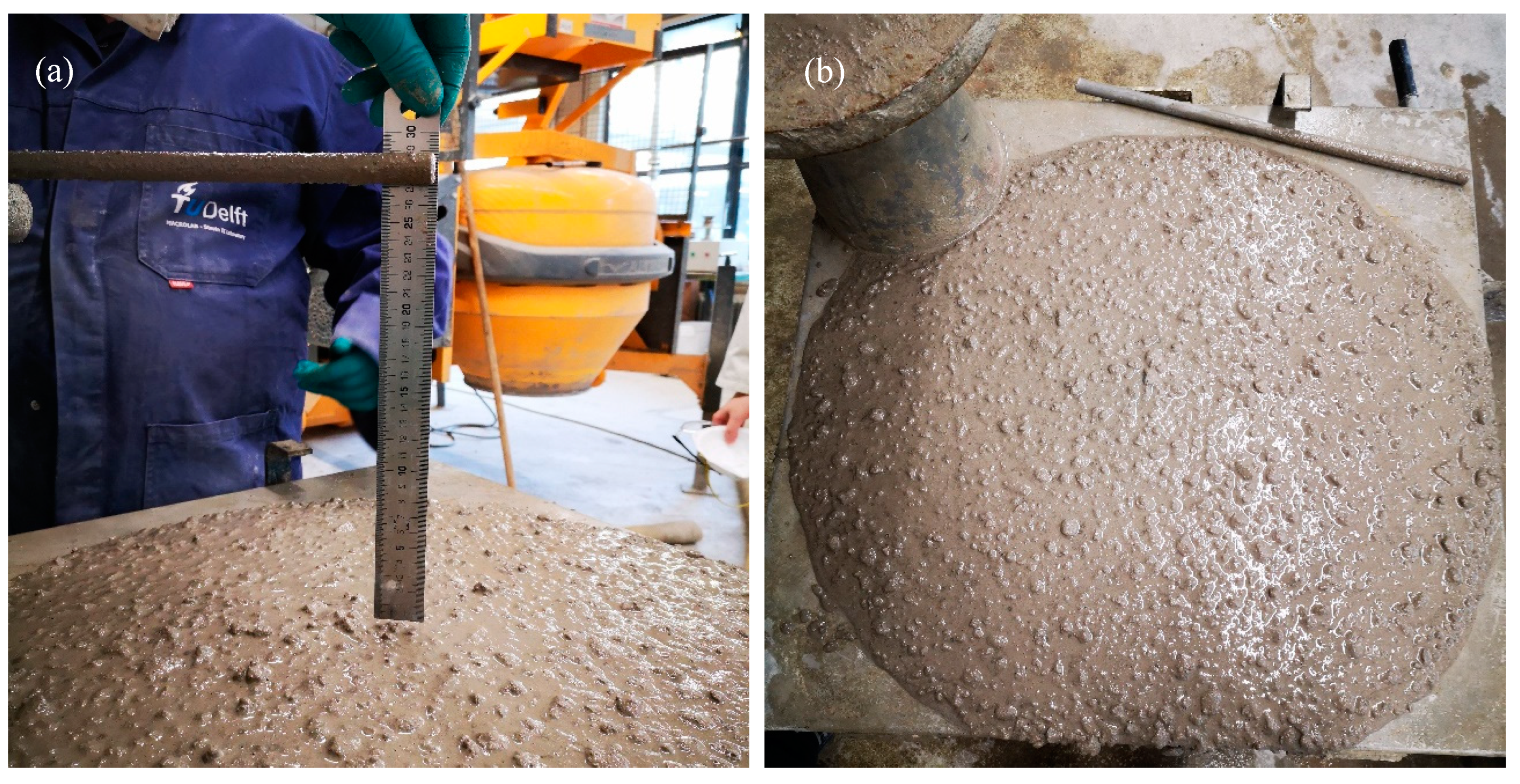
During the casting of AASFICMK concrete, a good flowability was observed. The slump of AASFICMK concrete was measured to be 280 mm (Figure 5a). The concrete quickly spread over the whole flow table (700 × 700 mm) after the cone was lifted up (Figure 5b). This slump flow value corresponded to the class SF2 for self-compacting concrete [32]. The initial and final setting times of AASFICMK measured by the Vicat method were 58 min and 117 min, respectively. The long setting time and the large slump flow indicated very good workability of AASFICMK concrete.
3.4. Strength of Concrete
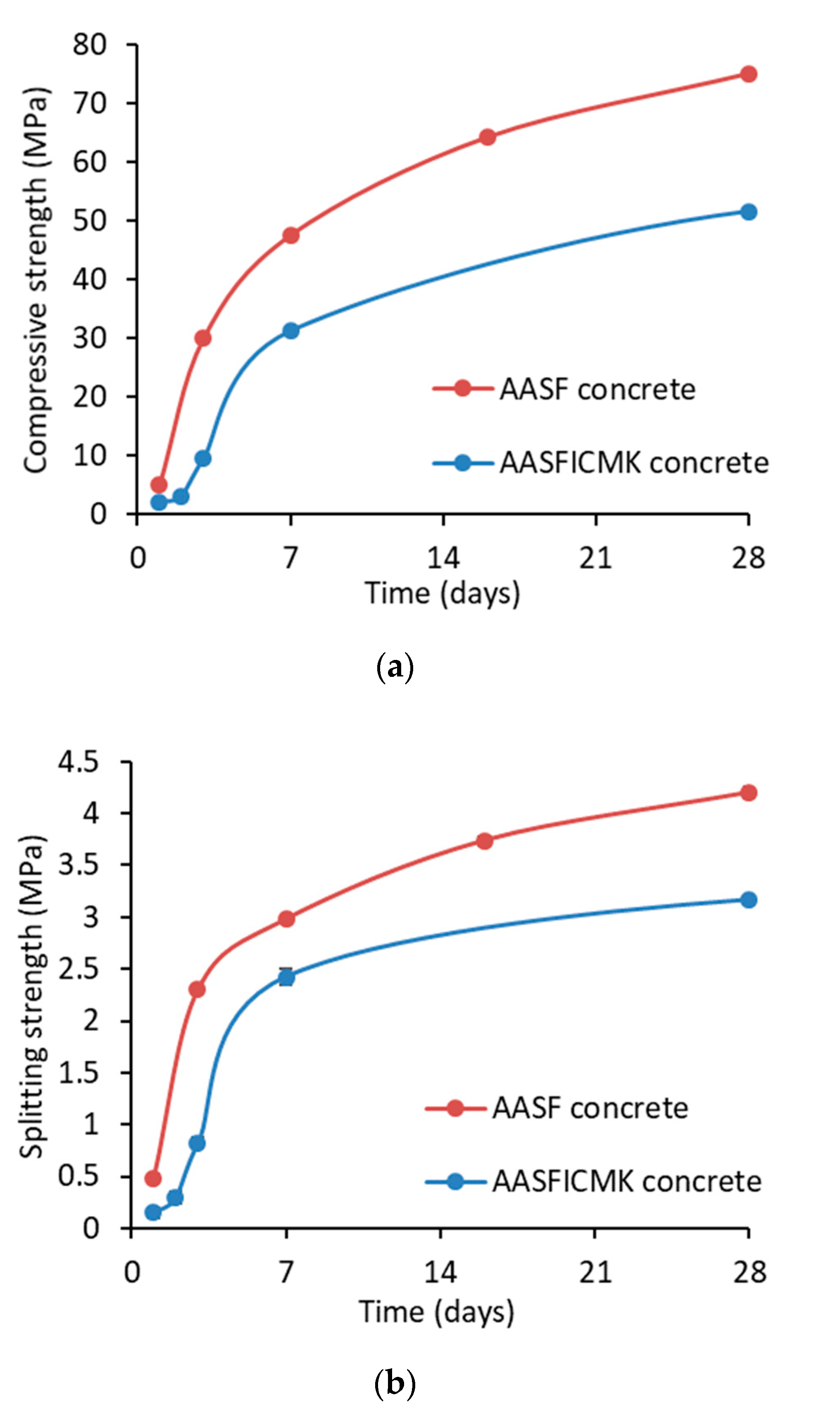
The strength development of AASFICMK concrete is shown in Figure 6 with the plain AASF concrete for comparison. It can be seen that with the incorporation of SAPs and MK, the compressive and splitting tensile strength of AASFICMK concrete was generally lower than that of AASF concrete. The reduced strength was contributed by both SAPs and MK. To provide internal curing to the concrete, extra liquid was added during mixing to be absorbed by the SAPs (see Table 4). The SAPs after absorption would act as liquid reservoirs during reaction and also as defects due to the large voids left when the liquid was released. The increased porosity of the concrete led to reduced strength [11]. Besides, the incorporation of MK was found to hinder the reaction rate in the acceleration period and could therefore reduce the strength in the very early age [17], although its impact on the 28-day strength was minor. When SAPs and MK were added together, their reducing effects were combined. Nonetheless, the 1-day compressive strength of AASFICMK concrete reached 2.1 MPa, which enabled a successful demolding at that age. The 28-day compressive strength of AASFICMK concrete reached 51 MPa, which was already sufficient for most structural uses as specified, for example, in the standard ACI 318 [33].
Besides strength values, the splitting tensile strength-to-compressive strength (ft/fc) ratio is also an important parameter that allows for the estimation of ft by knowing fc or vice versa [34]. The ratio also provides insight into the stress type (compression or tension) to which the concrete is more prone. The ft/fc ratio of AASFICMK concrete is compared with that of AASF concrete in Figure 7. On the first day, the ft/fc ratio of AASFICMK concrete was lower than that of AASF concrete which was probably because that the bonding between the aggregate and the paste in AASFICMK was still weak due to the retarding effect of MK and SAPs on the early-age reaction rates of AASF [10,11]. After the first day, however, the ft/fc ratios of AASFICMK concrete were always higher than those of AASF concrete. The higher ft/fc ratio of AASFICMK indicates that the incorporation of MK and SAPs could improve the tensile resistance of AASF concrete.
According to [31,35], a low ft/fc ratio is related to the development of microcracking in the concrete, for example in the paste surrounding aggregates, which harms the tensile strength more than the compressive strength of concrete. As shown in Figure 3 and Figure 4, the incorporation of SAPs and MK reduced the autogenous shrinkage and the cracking potential of AASF paste. Therefore, the development of microcracking in AASFICMK concrete was supposed to be less severe than in AASF concrete. This may be the main reason why AASFICMK concrete showed a higher ft/fc ratio than the plain AASF concrete. Whether the combination of SAPs and MK can reduce the autogenous shrinkage and the potential for cracking of concrete at the macro level will be verified in the next sections.
3.5. Autogenous Shrinkage of Concrete
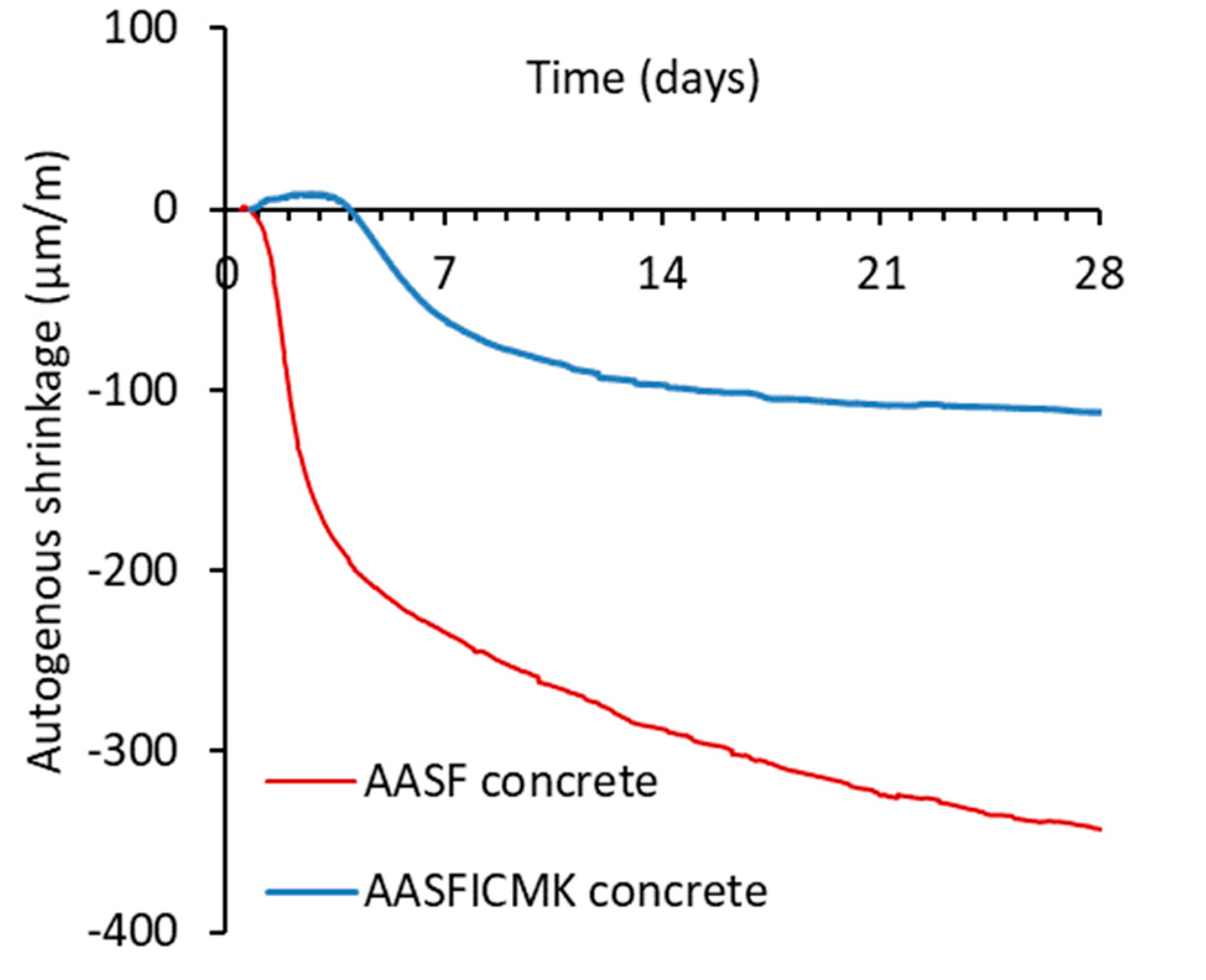
Figure 8 shows the autogenous shrinkage of the concrete. The plain AASF concrete showed large autogenous shrinkage, reaching more than 340 µm/m at the age of 28 days. In comparison, the autogenous shrinkage of AASFICMK concrete was less than 120 µm/m after a month of curing. This indicates that the utilization of SAPs and MK could effectively mitigate the autogenous shrinkage of AASF concrete. The autogenous shrinkage of AASFICMK was even lower than that of OPC concrete (see the results in [29,36]). The slight expansion of the concrete at an early age as shown in Figure 8 might be due to artifacts rather than a material behavior, since AASFICMK paste did not show expansion (see Figure 3). When stiffness of the concrete was low, the small pushing force from the LVDTs could move the embedded measuring bars a little bit, which enlarged the distance between the two measuring bars, even if the concrete itself did not expand [31]. After the first 3 days, the “expansion” was compensated by the shrinkage of the concrete.
3.6. Cracking Potential of Concrete
The stress evolutions in the plain AASF concrete and AASFICMK concrete are shown in Figure 9. A sudden drop in the stress to around zero indicated the failure of the concrete due to tensile stress. It can be seen that the stress generated in AASFICMK was much lower than that in AASF. In the first 4 days, a small compressive stress was detected in AASFICMK due to the slight “expansion” of the concrete (see Figure 8). Afterwards, a tensile stress started to develop. The stress in AASFICMK was only 50% and 30% of the stress in the plain AASF concrete at the age of 7 days and 14 days, respectively.
According to the cracking time and stress rate, the cracking potential of AASF concrete was classified as “moderate” [22]. With the incorporation of SAPs and MK, AASFICMK concrete did not crack within 56 days. The stress rate after the first week reached below 0.01 MPa/day, indicating a very “low” cracking potential of the concrete [22].
The superior workability, the high 28-day strength, and the low cracking potential indicate that AASFICMK concrete could be considered as a highly commercially competitive construction material. Furthermore, due to the very low cracking potential of AASFICMK concrete, there is a lot of room for further tailoring the current mixture design in order to reach optimal overall performance of the concrete for different applications. For example, for the cases where the autogenous shrinkage is not very critical, lower liquid/binder ratios, lower dosages of SAPs/MK or higher amounts of slag could be used, by which higher strength of the concrete can be easily achieved.
4. Conclusions
In this paper, internal curing by SAPs and incorporation of MK were used to mitigate the autogenous shrinkage of slag-and-fly-ash-based AAMs activated by NaOH/Na2SiO3. The ring test and TSTM were used to track the shrinkage-induced stress and cracking potential of the paste and concrete, respectively.
It was found that both SAPs and MK were effective in mitigating the autogenous shrinkage and the self-induced stress of AASF paste and concrete. The dosages of 0.16 wt. % of SAPs and 5 wt. % of MK are recommended, which yielded an alkali-activated concrete (AASFICMK) with very low autogenous shrinkage and cracking potential and high enough strength. AASFICMK concrete also showed satisfactory workability. These results indicate that SAPs and MK are promising admixtures to produce high-performance AASF concrete with low shrinkage.
Author Contributions
Z.L.: conceptualization, methodology, investigation, writing—original draft. X.Y.: investigation. Y.C.: investigation. T.L.: methodology. G.Y.: project administration, writing—review & editing. All authors have read and agreed to the published version of the manuscript.
Funding
This research is funded by the Netherlands Organisation for Scientific Research (NWO) under grant number of 15803 and China Scholarship Council (CSC) under grant number of 201506120072 and 201906050022.
Acknowledgments
Maiko van Leeuwen is also gratefully acknowledged for his help with the experiments.
Conflicts of Interest
The authors declare that they have no conflict of interest.
References
- Duxson, P.; Provis, J.L.; Lukey, G.C.; van Deventer, J.S.J. The role of inorganic polymer technology in the development of ‘green concrete’. Cem. Concr. Res. 2007, 37, 1590–1597. [Google Scholar] [CrossRef]
- Provis, J.L.; Van Deventer, J.S.J. Geopolymers: Structures, Processing, Properties and Industrial Applications; Woodhead: Cambridge, UK, 2009. [Google Scholar]
- Arbi, K.; Nedeljković, M.; Zuo, Y.; Ye, G. A Review on the Durability of Alkali-Activated Fly Ash/Slag Systems: Advances, Issues, and Perspectives. Ind. Eng. Chem. Res. 2016, 55, 5439–5453. [Google Scholar] [CrossRef] [Green Version]
- Fang, G.; Ho, W.K.; Tu, W.; Zhang, M. Workability and mechanical properties of alkali-activated fly ash-slag concrete cured at ambient temperature. Constr. Build. Mater. 2018, 172, 476–487. [Google Scholar] [CrossRef]
- Cartwright, C.; Rajabipour, F.; Radli, A. Shrinkage Characteristics of Alkali-Activated Slag Cements. J. Mater. Civ. Eng. 2014, 27, 1–9. [Google Scholar] [CrossRef]
- Nedeljković, M.; Li, Z.; Ye, G. Setting, Strength, and Autogenous Shrinkage of Alkali-Activated Fly Ash and Slag Pastes: Effect of Slag Content. Materials 2018, 11, 2121. [Google Scholar] [CrossRef] [Green Version]
- Bilek, V., Jr.; Kalina, L.; Fojtík, O. Shrinkage-Reducing Admixture Efficiency in Alkali-Activated Slag across the Different Doses of Activator. In Key Engineering Materials; Trans Tech Publications Ltd.: Zurich, Switzerland, 2018; Volume 761, pp. 19–22. [Google Scholar]
- Ye, H.; Radlińska, A. Shrinkage mitigation strategies in alkali-activated slag. Cem. Concr. Res. 2017, 101, 131–143. [Google Scholar] [CrossRef]
- Bakharev, T.; Sanjayan, J.G.; Cheng, Y. Effect of elevated temperature curing on properties of alkali-activated slag concrete. Cem. Concr. Res. 1999, 29, 1619–1625. [Google Scholar] [CrossRef]
- Li, Z.; Nedeljković, M.; Chen, B.; Ye, G. Mitigating the autogenous shrinkage of alkali-activated slag by metakaolin. Cem. Concr. Res. 2019, 122, 30–41. [Google Scholar] [CrossRef]
- Li, Z.; Wyrzykowski, M.; Dong, H.; Granja, J.; Azenha, M.; Lura, P.; Ye, G. Internal curing by superabsorbent polymers in alkali-activated slag. Cem. Concr. Res. 2020, 135, 106123. [Google Scholar] [CrossRef]
- Tu, W.; Zhu, Y.; Fang, G.; Wang, X.; Zhang, M. Internal curing of alkali-activated fly ash-slag pastes using superabsorbent polymer. Cem. Concr. Res. 2019, 116, 179–190. [Google Scholar] [CrossRef] [Green Version]
- Li, Z.; Zhang, S.; Liang, X.; Ye, G. Internal curing of alkali-activated slag-fly ash paste with superabsorbent polymers. Constr. Build. Mater. 2020. under peer review. [Google Scholar]
- Li, Z.; Ye, G. Experimental study of the chemical deformation of metakaolin based geopolymer. In Proceedings of the SynerCrete’18 International Conference on Interdisciplinary Approaches for Cement-based Materials and Structural Concrete, Funchal, Portugal, 24–26 October 2018; pp. 443–448. [Google Scholar]
- ASTM C1608. Standard Test Method for Chemical Shrinkage of Hydraulic Cement Paste; ASTM: West Conshohocken, PA, USA, 2007; pp. 667–670. [Google Scholar]
- Li, Z.; Zhang, S.; Zuo, Y.; Chen, W.; Ye, G. Chemical deformation of metakaolin based geopolymer. Cem. Concr. Res. 2019, 120, 108–118. [Google Scholar] [CrossRef]
- Li, Z.; Liang, X.; Chen, Y.; Ye, G. Effect of metakaolin on the autogenous shrinkage of alkali-activated slag-fly ash paste. Constr. Build. Mater. 2020. under peer review. [Google Scholar]
- ASTM C1968. Standard Test Method for Autogenous Strain of Cement Paste and Mortar; ASTM: West Conshohocken, PA, USA, 2013; pp. 1–8. [Google Scholar] [CrossRef]
- Li, Z.; Lu, T.; Liang, X.; Dong, H.; Ye, G. Mechanisms of autogenous shrinkage of alkali-activated slag and fly ash pastes. Cem. Concr. Res. 2020, 135, 106107. [Google Scholar] [CrossRef]
- Eren, Ö.; Abdalkader, A.H.M. Plastic shrinkage cracking of fiber reinforced concrete. In Proceedings of the 10th East Asia-Pacific Conference on Structural Engineering and Construction (EASEC), Bankok, Thailand, 3–5 August 2006; pp. 473–480. [Google Scholar] [CrossRef]
- Hossain, A.B.; Weiss, J. Assessing residual stress development and stress relaxation in restrained concrete ring specimens. Cem. Concr. Compos. 2004, 26, 531–540. [Google Scholar] [CrossRef]
- ASTM C1581. Standard Test Method for Determining Age at Cracking and Induced Tensile Stress Characteristics of Mortar and Concrete under Restrained Shrinkage; ASTM: West Conshohocken, PA, USA, 2009; pp. 1–7. [Google Scholar] [CrossRef]
- Schlitter, J.L.; Senter, A.H.; Bentz, D.P.; Nantung, T.; Weiss, W.J. A dual concentric ring test for evaluating residual stress development due to restrained volume change. J. ASTM Int. 2010, 7, 1–13. [Google Scholar]
- NEN-EN 12350-2. Testing Fresh Concrete—Part 2: Slump-Test; BSI: London, UK, 2009. [Google Scholar]
- ASTM C191. Standard Test Methods for Time of Setting of Hydraulic Cement by Vicat Needle BT—Standard Test Methods for Time of Setting of Hydraulic Cement by Vicat Needle; ASTM: West Conshohocken, PA, USA, 2013. [Google Scholar]
- Lokhorst, S.J. Deformational Behaviour of Concrete Influenced by Hydration Related Changes of the Microstructure; Delft University of Technology: Delft, The Netherlands, 2001. [Google Scholar]
- NEN-EN 12390-3. Testing hardened concrete—Part 3: Compressive Strength of Test Specimens; BSI: London, UK, 2009. [Google Scholar]
- Sule, M.S. Effect of Reinforcement on Early-Age Cracking in High Strength Concrete; Delft University of Technology: Delft, The Netherlands, 2003. [Google Scholar]
- Lura, P. Autogenous Deformation and Internal Curing of Concrete; Delft University of Technology: Delft, The Netherlands, 2003. [Google Scholar]
- Lu, T.; Li, Z.; Huang, H. Effect of Supplementary Materials on the Autogenous Shrinkage of Cement Paste. Materials 2020, 13, 3367. [Google Scholar] [CrossRef]
- Li, Z.; Zhang, S.; Liang, X.; Ye, G. Cracking potential of alkali-activated slag and fly ash concrete subjected to restrained autogenous shrinkage. Cem. Concr. Compos. 2020, 103767. [Google Scholar] [CrossRef]
- NEN-EN 12350-8. Testing Fresh Concrete—Part 8: Self-Compacting Concrete—Slump-Flow Test; BSI: London, UK, 2019. [Google Scholar]
- ACI (American Concrete Institute). Building Code Requirements for Structural Concrete and Commentary; ACI: Brussels, Belgium, 2011. [Google Scholar]
- Arioglu, N.; Canan Girgin, Z.; Arioglu, E. Evaluation of ratio between splitting tensile strength and compressive strength for concretes up to 120 MPa and its application in strength criterion. ACI Mater. J. 2006, 103, 18–24. [Google Scholar]
- Li, Z.; Lu, T.; Chen, Y.; Wu, B.; Ye, G. Prediction of the autogenous shrinkage of alkali-activated slag and fly ash concrete. Mater. Struct. 2020. under peer review. [Google Scholar]
- Darquennes, A.; Staquet, S.; Delplancke-Ogletree, M.P.; Espion, B. Effect of autogenous deformation on the cracking risk of slag cement concretes. Cem. Concr. Compos. 2011, 33, 368–379. [Google Scholar] [CrossRef]
Figure 1.
Dimensions of the steel rings, after [22].
Figure 1.
Dimensions of the steel rings, after [22].

Figure 2.
Overview of the set-up for the concrete properties, after [28]. Top left: ADTM. Top middle: Cubes. Bottom left: TSTM. Bottom right: controlling systems.
Figure 2.
Overview of the set-up for the concrete properties, after [28]. Top left: ADTM. Top middle: Cubes. Bottom left: TSTM. Bottom right: controlling systems.

Figure 3.
Autogenous shrinkage of AASF paste with SAPs and/or MK.

Figure 4.
Autogenous-shrinkage-induced stress in AASF paste with SAPs and/or MK. A logarithmic scale is used on the x-axis in order to distinguish individual curves. The small fluctuation of the stress in AASFICMK paste on around 20 days and 30 days was due to the temperature fluctuation in the curing room.

Figure 5.
Slump (a) and flowability (b) of AASFICMK concrete.

Figure 6.
Compressive (a) and splitting strength (b) of AASFICMK concrete in comparison with AASF concrete. For splitting strength, the error bar is shown in the diagram, but it is too small to be clearly distinguished from the marker.
Figure 6.
Compressive (a) and splitting strength (b) of AASFICMK concrete in comparison with AASF concrete. For splitting strength, the error bar is shown in the diagram, but it is too small to be clearly distinguished from the marker.

Figure 7.
Splitting tensile strength-to-compressive strength (ft/fc) ratios of AASFICMK concrete, in comparison with AASF concrete.
Figure 7.
Splitting tensile strength-to-compressive strength (ft/fc) ratios of AASFICMK concrete, in comparison with AASF concrete.

Figure 8.
Autogenous shrinkage of AASF and AASFICMK concrete.

Figure 9.
Self-induced stress in AASF and AASFICMK concrete.


Table 1.
Chemical compositions of slag, fly ash and MK.
| Oxide (wt. %) | SiO2 | Al2O3 | CaO | MgO | Fe2O3 | SO3 | K2O | TiO2 | Other |
|---|---|---|---|---|---|---|---|---|---|
| Slag | 31.8 | 13.3 | 40.5 | 9.3 | 0.5 | 1.5 | 0.3 | 1.0 | 1.9 |
| Fly ash | 56.8 | 23.8 | 4.8 | 1.5 | 7.2 | 0.3 | 1.6 | 1.2 | 2.8 |
| MK | 55.1 | 38.4 | 0.6 | - | 2.6 | - | 0.2 | 1.1 | 2.1 |
Table 2.
Particle size and density of slag, fly ash and MK.
| Particle Size (µm) | Density (g/cm3) | |||
|---|---|---|---|---|
| D10 | D50 | D90 | ||
| Slag | 4.6 | 18.3 | 33.2 | 2.9 |
| Fly ash | 10.6 | 48.1 | 83.4 | 2.4 |
| MK | 27.0 | 69.4 | 113.5 | 2.7 |
Table 3.
Mixture proportions of AASF paste with SAPs and/or MK.
| Composition (wt. %) | AASF Paste | AASFIC | AASFMK | AASFICMK |
|---|---|---|---|---|
| Slag | 1 | 1 | 0.9 | 0.9 |
| Fly ash | 1 | 1 | 1 | 1 |
| Activator | 1 | 1 | 1 | 1 |
| SAPs | - | 0.0032 | - | 0.0032 |
| Extra activator for internal curing | - | 0.064 | - | 0.064 |
| MK | - | - | 0.1 | 0.1 |
Table 4.
Mixture proportions of AASF and AASFICMK concrete.
| Composition (kg/m3 of Concrete) | AASF Concrete | AASFICMK Concrete |
|---|---|---|
| Slag | 200 | 180 |
| Fly ash | 200 | 200 |
| Activator | 200 | 200 |
| SAPs | - | 0.64 |
| Extra activator for internal curing | - | 12.8 |
| MK | - | 20 |
| Aggregate (0–4 mm) | 789 | 789 |
| Aggregate (4–8 mm) | 440 | 440 |
| Aggregate (8–16 mm) | 525 | 525 |
© 2020 by the authors. Licensee MDPI, Basel, Switzerland. This article is an open access article distributed under the terms and conditions of the Creative Commons Attribution (CC BY) license (http://creativecommons.org/licenses/by/4.0/).
Share and Cite
MDPI and ACS Style
Li, Z.; Yao, X.; Chen, Y.; Lu, T.; Ye, G. A Low-Autogenous-Shrinkage Alkali-Activated Slag and Fly Ash Concrete. Appl. Sci. 2020, 10, 6092. https://0-doi-org.brum.beds.ac.uk/10.3390/app10176092
AMA Style
Li Z, Yao X, Chen Y, Lu T, Ye G. A Low-Autogenous-Shrinkage Alkali-Activated Slag and Fly Ash Concrete. Applied Sciences. 2020; 10(17):6092. https://0-doi-org.brum.beds.ac.uk/10.3390/app10176092
Chicago/Turabian StyleLi, Zhenming, Xingliang Yao, Yun Chen, Tianshi Lu, and Guang Ye. 2020. "A Low-Autogenous-Shrinkage Alkali-Activated Slag and Fly Ash Concrete" Applied Sciences 10, no. 17: 6092. https://0-doi-org.brum.beds.ac.uk/10.3390/app10176092
Note that from the first issue of 2016, this journal uses article numbers instead of page numbers. See further details here.