Electrical Monitoring under Transient Conditions: A New Paradigm in Electric Motors Predictive Maintenance


Instituto Tecnológico de la Energía, Universitat Politècnica de València (UPV), Camino de Vera s/n, 46022 Valencia, Spain
Appl. Sci. 2020, 10(17), 6137; https://0-doi-org.brum.beds.ac.uk/10.3390/app10176137
Submission received: 14 August 2020
/
Revised: 27 August 2020
/
Accepted: 29 August 2020
/
Published: 3 September 2020
(This article belongs to the Special Issue 10th Anniversary of Applied Sciences: Invited Papers in Mechanical Engineering Section)
Abstract
:Featured Application
Electric motors condition monitoring.
Abstract
Electric motors condition monitoring is a field of paramount importance for industry. In recent decades, there has been a continuous effort to investigate new techniques and methods that are able to determine the health of these machines with high accuracy and reliability. Classical methods based on the analysis of diverse machine quantities under stationary conditions are being replaced by modern methodologies that are adapted to any operation regime of the machine (including transients). These new methods (especially those based on motor startup signal monitoring), which imply the use of advanced signal processing tools, have shown great potential and have provided spectacular advantages versus conventional approaches enabling, among other facts, a much more reliable determination of the machine health. This paper reviews the background of this recent condition monitoring trend and shows the advantages of this new approach with regard to its application to the analysis of electrical quantities. Examples referred to its application to real motors operating in industry are included, proving the huge potential of the transient-based approach and its benefits versus conventional methods.
1. Introduction
According to some surveys, there are more than 300 million electric motors worldwide [1]. Most of them are used to drive diverse types of industrial machinery in a wide range of industrial areas (steel, paper, cement, petrochemical, mining industries…). However, their use also expands to other applications that play a capital role for the development of today’s societies, such as electric vehicles, traction systems, aerospace applications, or even robotics. In 2017, the global electric motor market size reached $96,967.9 million [2], which gives an idea of the significance of these machines in modern societies.
Due to the vast utilization of electric motors, the monitoring of their condition is an area of capital importance for industry. Large electric motors are especially relevant due to their high costs (a single MW motor can reach a cost above $1 million), criticality, and complex repairs. An inspection of a large motor can imply expenses of several thousands of dollars, especially if it requires motor disassembly. Moreover, unexpected faults in these machines may lead to losses in the range of millions of dollars, as reported in some applications [3], due to production downtimes and repair costs, among others. If these facts were not enough, the presence of anomalies or defects in a machine, even if not leading to machine shutdowns, also affect its efficiency, leading to significant decrements that may make the selection of high-efficiency motors (class IE4, IE5…) useless in the applications in which they intervene. In this regard, recent works proved that the existence of rotor problems, stator asymmetries, cooling system defects, bearing faults, or coupling system problems may yield important drops in the efficiency of the machine [4], which is a repercussion that reinforced the importance of a proper knowledge of the health of these machines.
Despite electric motors being quite reliable machines in general (especially the induction motors that are the most widespread in industry), they are prone to suffer different types of failures. Several surveys have pointed out that bearing failures and stator insulation faults are the most frequent [5], but other failures, such as rotor damages, core defects, or cooling system problems may also have very negative consequences for the motor integrity and performance.
Over recent decades, there has been an increasing effort oriented toward the development of predictive maintenance techniques to determine the condition of certain parts of the machines. These techniques rely on monitoring different motor quantities (currents, vibrations, temperatures, fluxes, partial discharges…) and analyzing them properly to detect possible evidences of the development of the fault. After many years of investigations in this area, one of the most important conclusions is that there is no method relying on a single quantity that is able to determine the integral condition of the whole motor, since each specific technique has shown good results for the diagnosis of certain faults but not for others. For instance, vibration data analysis is universally accepted as an excellent technique for the detection of mechanical failures, but its sensitivity is much worse when detecting other types of faults. As a result of the previous facts, the current trend is to develop intelligent systems that combine the information obtained from the application of diverse techniques based on the analysis of different quantities. The fact of relying on multiple and complementary informational sources enables reaching a more accurate and robust conclusion of the integral motor health. This idea is illustrated in Figure 1.
During recent decades, it has been discovered that under some situations, very well-established condition monitoring techniques (such as current or vibration analysis) may fail, even when diagnosing the faults for which they are theoretically more suitable. This can be due either to an erroneous utilization of the technique or to the individual characteristics or operation conditions of the machine. For instance, the classical method based on the analysis of motor currents, known as Motor Current Signature Analysis (MCSA) [6] has led to erratic diagnostic conclusions when diagnosing rotor damages under variable speed conditions (e.g., in mining applications, as reported in [7]). Moreover, during recent years, some researchers have discovered that certain constructive characteristics of the motor (e.g., existence of cooling axial ducts, rotor core magnetic anisotropy issues, double cage rotors…) and certain operational conditions of the machine (e.g., operation under reduced slips, existence of load torque oscillations, passing frequencies of the components of certain types of loads…) may lead to false indications (positive or negative) when MCSA is applied to the detection of rotor asymmetries [8,9] and other faults. This situation is illustrated in Table 1 that shows how there are cases in which this consolidated technique may yield erroneous diagnostics. This lack of reliability is also common for other predictive maintenance methods that are widespread in industry.
Due to the aforementioned constraints of the techniques currently available in industry, there has been intense research activity oriented toward the development of new methodologies that can overcome the drawbacks of these existing technologies. In this context, one of the most promising trends that has emerged in the condition monitoring area over recent years relies on the development of advanced techniques that are based on the analysis of quantities under any operation regime of the machine (including transients, i.e., operation regimes during which the speed of the machine varies such as motor starting, plug stopping, load variations…) [9]. Indeed, it been proven that the analysis of transient quantities can provide very useful information for the diagnosis, avoiding false indications of classical methods. The underlying idea of this new approach is simple: unlike the classical stationary methods that rely on the analysis of steady-state quantities (currents, vibrations, fluxes…) and the further detection of fault-related harmonics in the resulting Fourier spectra, the new transient-based methods are based on the identification of the time-frequency evolutions that are followed by the fault-related components during the transient [9]. To detect these evolutions, it is necessary to analyze the corresponding transient signals by applying advanced signal processing tools, which are known as time-frequency transforms. To sum up, this new diagnosis trend relies on identifying characteristic evolutions caused by fault components in the time-frequency maps resulting from the analysis of transient signals. Over recent years, this new approach has been applied with success to transient current, stray flux, and even vibration signals, yielding important advantages versus conventional approaches. These advantages can be synthesized in the following points:
- -
- Avoidance of false indications: the time-frequency analyses of starting currents or fluxes have proven to be immune to some phenomena that may yield false indications when classical approaches are employed (e.g., presence of cooling ducts, existence of load torque oscillations, diagnosis of outer cage breakage in double cage rotors, existence of rotor magnetic anisotropy, influence of blade pass frequencies caused by certain loads…).
- -
- High reliability in the diagnostic: since the diagnosis is based on the identification of the time-evolutions of frequency components, it is much more reliable than that relying on the assessment of single frequency components in the Fourier spectra; in other words, the time-frequency (t-f) patterns raising in the resulting t-f maps are less likely to be masked or interfered by other phenomena than a specific peak in the spectrum. If this were not enough, the diagnosis does not rely on a single evolution but on the multiple evolutions caused by the fault harmonics under the considered transient.
- -
- Suitability for different operation regimes: the analysis of transient quantities yields correct diagnosis conclusions regardless of the load level of the machine. Therefore, it is perfectly valid for machines operating under reduced slip conditions, provided that the transient is long enough. This does not happen with the conventional methods, such as MCSA. Moreover, the new methodology is especially valid for applications subjected to frequent transients (traction systems, renewable energy applications), since the employed tools are especially suited for these regimes. Again, the conventional methods, such as MCSA, are restricted to stationary conditions, providing possible wrong diagnostics in applications in which either the speed or the supply frequency changes during the capture [7].
The previous advantages are especially relevant in the case of large motors in which a correct diagnostic conclusion is critical. On the one hand, the decision of inspecting the machine is not trivial, since significant transportation and disassembly costs are involved (leaving aside the costs associated to the interruption of the production): hence, possible false positive indications must be avoided, because these could lead to unnecessarily incur in these costs. At the same time, it is crucial to detect the presence of the fault if it exists, since eventual false negative indications (i.e., fault remains undetected) may imply even higher losses for the company due to unplanned production downtimes. In this context, the application of these modern and powerful technologies plays a crucial role to reach a diagnosis with maximum reliability.
The present paper intends to review the basic operation of the modern transient-based methodologies that have been proposed over recent years to electrical quantities of the motor, emphasizing their application to starting current and stray flux signals. Moreover, the paper includes several examples that prove the reliability of these approaches and demonstrate their usefulness, even in cases in which the classical techniques, such as MCSA or vibration data analysis, may fail. The paper is intended to provide the researchers involved in the electric motors condition monitoring area a reference document that gives them the guidelines of this powerful methodology that is changing the vision of the electric motors faults diagnosis community.
2. Foundations of the Transient Analysis of Electrical Quantities
The underlying idea of the new diagnosis approach based on transient analysis relies on the fact that the fault harmonics, which fall at specific frequency values at steady-state (provided that the slip remains constant), change in frequency and time under transient operation. The most illustrative example of this fact is the Lower Sideband Harmonic (LSH), which is typically associated with rotor damages and the frequency of which is given by Equation (1), where s is the slip of the machine (s =, with ns = synchronous speed and n = motor speed) and f is the supply frequency.
At steady state, the frequency of the LSH is constant, and both s and f remain stable always. However, under any transient regime provoking a variation of either s or f, the frequency of this harmonic will change in a characteristic manner, in coherence with the variation of these parameters. A typical example is the direct on-line starting of an induction motor: under that transient, the slip decreases from s = 1 (when the motor is connected) to near zero (when the steady-state regime is reached). Consequently, the frequency of the LSH (fLSH) will evolve accordingly, namely: it will drop from fLSH = f (when s = 1, at the beginning of the starting) to fLSH = 0 and it will later increase again to fLSH ≈ f (when s ≈ 0 at steady-state). Therefore, fLSH will follow a very characteristic evolution during the starting that resembles a V-pattern. The detection and quantification of this evolution, which has been well characterized in many previous works [8,10], is a reliable evidence of the presence of the harmonic and therefore of the existence of rotor damage.
In order to detect this type of time-frequency evolution of fault-related harmonics (such as the LSH), suitable signal processing tools must be applied to the considered transient quantities. These tools, detailed in the next section, are known as time-frequency transforms and extract the time-frequency content of the analyzed signal, so that they enable visualizing, not only which frequencies are present in that signal, but also how they evolve over time.
The following subsections describe the way in which the explained transient-based methodology is applied to diverse motor quantities, such as currents and stray-fluxes, which are captured during the transient operation of the motor.
2.1. Transient Analysis of Motor Currents
The transient-based methodology described before was firstly applied to the analysis of transient motor currents. The procedure relies on capturing the current demanded by the motor under transient operation of the machine. Although the methodology has been successfully applied to different types of transient currents (load variations, plugging stop, deceleration, supply frequency changes…), the starting transient is the one that has summoned most of the attention. Many works in the last decade have deepened the investigation and characterization of the evolutions of the fault harmonics present in the starting current for the detection of different faults [8,9,10].
The main advantages of the analysis of starting currents are derived from the benefits that are inherent to the analysis of motor currents: unlike other quantities, the current can be measured without the need to access the motor (e.g., in the motor control center (M.C.C) or motor panelboard), hence enabling the remote monitoring of the motor condition. Moreover, the measurement can be carried out in the secondary windings of current transformers (CTs) that are employed for measurement devices with maximum safety and comfortability conditions. The equipment needed for the signal acquisition is simple: a single current clamp and an oscilloscope with minimum requirements are enough, and only one phase current is required. Finally, the current analysis enables a broad fault coverage (bearing always in mind that no quantity enables the integral monitoring of the whole motor condition) [18].
The analysis of starting currents begins with the registration of the current waveform under a starting of the electric motor; this signal is later transferred to a computer for its analysis. The application of suitable time-frequency transforms to this signal enables obtaining the t-f maps, where the possible evolutions of fault components will be identified. Moreover, appropriate fault severity indicators are computed based on certain parameters of these maps (for instance, the energy density at strategic t-f regions), which enable determining the level of failure. Depending on the fault that is diagnosed, different harmonic evolutions must be identified in the maps. For instance, in the case of rotor damages, the most relevant evolutions are those of the LSH (V-shaped pattern described above) and that of the Upper Sideband Harmonic (USH), the frequency of which starts at 3 f and ends at near f at steady-state. However, apart from these, there are different families of harmonics that are also amplified by this failure, and since each harmonic has its own evolution, there will be additional patterns caused by these components that may serve to ratify the presence of the fault [8].
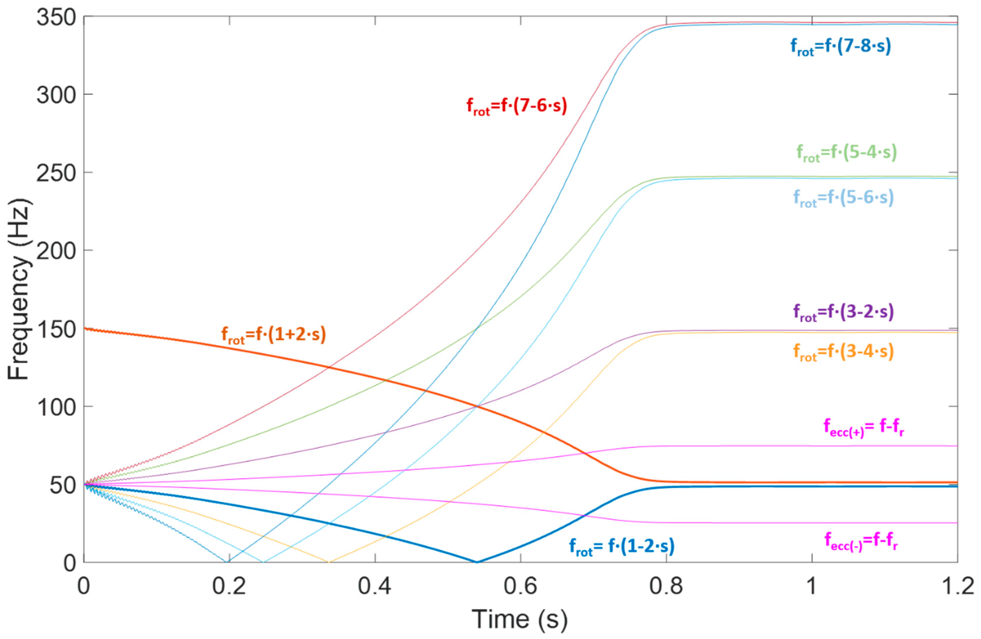
On the other hand, in case of eccentricities or misalignments, rather different components evolutions will appear. The most relevant are those of the components f − fr and f + fr that evolve from the supply frequency (f) toward their final frequencies at steady state (approximately f/2 and 3·f/2) for a machine with two pole pairs) [19]. Figure 2 shows the expected evolutions for the most relevant harmonics associated to rotor damages (denoted by frot) and eccentricities/misalignments (denoted by fecc) that are present in the motor starting current, considering a direct on-line starting.
Note that, similarly with what happened with rotor damages or eccentricities, other types of failures will yield their corresponding evolutions under starting. This is the case of bearing failures or even coupling system problems (faults linked to belt/pulleys systems or gear reducers) [20]. This confers an additional potential to the approach, since it may be applied to a wide range of potential motor faults.
It is also important to remark that the aforementioned evolutions are valid for the case of direct on-line starting of electric motors. However, some works have proven that they are also valid under other types of starting methods [21]: startup with auto-transformer, startup with stator resistors, star-delta startup, or even soft-started motors. In this latter case, a higher harmonic content is detected in the signals, but the fault-related patterns still appear [22]. A different question arises when the motor is started via Variable Speed Drive (VSD). In that case, since the supply frequency usually changes, the patterns linked with the fault components are different, but once they are characterized, the methodology is perfectly applicable, as reported in previous works that considered motors driven by a frequency converter [23,24].
2.2. Transient Analysis of Stray Fluxes
During these recent years, the transient-based methodology approach that had been successfully applied to motor currents (and, more specifically, to starting currents) was extrapolated to the analysis of other electrical quantities, such as stray fluxes. Since the early 2000s, it had been observed that the installation of external coil sensors attached to the motor frame and the further analysis of the electromotive force (emf) signals that the stray flux induces in these sensors is a powerful source of information for the diagnosis of many faults [25,26,27]. Different authors demonstrated the theoretical expressions of the harmonics that were amplified by rotor damages, eccentricities, stator faults, and even coupling system problems at the induced emf signals under the steady-state regime. Most of these harmonics are slip-dependant, and many of them are coincident with those appearing in the stator current spectra. Therefore, the analysis of steady-state stray flux signals became an interesting alternative for the diagnosis, following a similar procedure than that employed for MCSA.
With the advent and development of the transient-based diagnosis approaches and the better knowledge of the signal processing tools that are available for the analysis of non-stationary signals, some works proposed the use of this technology for the diagnosis of emf signals that were induced by the stray flux under the transient operation of the machine. Some authors [28,29,30] deepened the study of the transient emf signals that were induced under starting, proving that this analysis is a robust source of information for the diagnosis of many faults such as rotor asymmetries (both in cage and in wound rotor induction motors), eccentricities, and misalignments.
In comparison with the current analysis, the advantages of analyzing stray flux signals rely on the much richer harmonic content of the registered signals (this means that many more evolutions can be identified in the time-frequency maps and employed to diagnose the fault) and the lower influence of load-related problems, a fact that may help to discriminate between motor and load-related anomalies (e.g., eccentricities and misalignments) [31,32]. Moreover, some motor manufacturers are incorporating embedded flux sensors in their machines, which will enhance the potential penetrability of the technique in the industry in the near future [33,34].
However, the technique relying on the analysis of the stray flux has drawbacks also. One of them is the strong influence of the sensor position in the results; it has been proven that depending on the sensor location, the flux captured can be primarily radial or axial, and hence, the corresponding components (axial/radial) will be more observable in the resulting time-frequency maps. The point is that combining the information coming from different sensor locations can enhance the diagnosis, since more fault components of different nature can be identified [35]. On the other hand, the fault severity thresholds based on flux analysis are still less mature than those based on currents, which have been validated over the years.
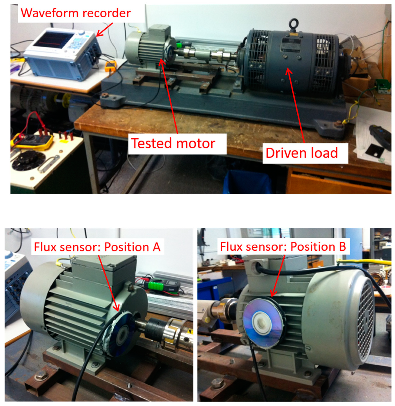
Usually, the most common locations for the stray flux sensors are those depicted in Figure 3. As reported in several works [36,37], depending on the sensor position, a higher portion of axial or radial flux will be captured, and therefore, the corresponding components (axial or radial) will be present in the results of the analyses of the corresponding signal. In this regard, at Position A, the sensor mainly captures axial flux. On the contrary, the flux captured at Position C is primordially radial. Finally, Position B captures a portion of axial and a portion of radial flux.
The authors of different works have demonstrated that each particular fault may lead to the amplification of components of different nature in the stray flux signals. For instance, the presence of rotor damages amplifies two types of components in the stray flux spectrum [36]: axial components (the most representative are those located at s·f and 3·s·f) and radial components (the most relevant are the sideband components, LSH and USH). On the other hand, the existence of eccentricities yields components at f ± fr, but these are less affected by misalignments or load problems than the corresponding ones in the current spectrum, as reported in some works [38].
3. Signal Processing Tools
The application of the new transient-based diagnosis approaches implies the use of special signal processing tools that are able to provide a time-frequency representation of the analyzed transient signal (e.g., starting currents or fluxes). These are known as time-frequency transforms, and they enable tracking the time-frequency evolutions of the fault components during the corresponding transient as well as to compute the corresponding fault severity indicators based on these evolutions. There is a wide variety of available time-frequency transforms, each of them having its respective advantages and drawbacks. The research carried out in the last years has yielded two main groups of t-f transforms: discrete and continuous [40]. Table 2 shows the respective advantages and drawbacks and specifies some representative examples of each group (note: DWT = Discrete Wavelet Transform; UDWT = Undecimated Discrete Wavelet Transform; WP = Wavelet Packets; CWT = Continuous Wavelet Transform; HHT = Hilbert–Huang Transform; WVD = Wigner–Ville Distribution; CWD = Choi–Williams Distributions). Based on the comments specified there, the discrete transforms seem to be better suited for online diagnosis systems or portable condition monitoring devices where an instantaneous diagnosis is required, whereas the continuous transforms are more suitable for off-line and detailed diagnostics of the motor condition.
4. Results
This section presents examples of the application of transient-based diagnostics to the diagnosis of different faults in induction motors. The results shown in the section includes both the application of starting current and starting flux analysis to laboratory motors, as well as different cases referred to the application of transient analysis of electrical quantities to field machines.
4.1. Results in Laboratory Motors
Several tests were carried out in the laboratory using different 1.1 kW, 4 pole cage induction motors with different levels of rotor failure and misalignment [10]. In the experiments, the tested motor was coupled to a DC that had the function of load. In each test, the motor was started direct on-line, and it operated until the steady-state regime was well reached; the phase current waveform under the starting was captured by means of a current clamp that was connected to the oscilloscope. In addition, a self-built flux sensor (manufactured at Universitat Politecnica de Valencia, Valencia, Spain) based on a coil with 1000 turns was attached to the external part of the motor frame [28]. The waveform of the electromotive force (emf) induced in the sensor by the stray flux was registered by means of the previous oscilloscope. Different tests were performed for the motor operating under various levels of failures and under different loading conditions. Moreover, different locations of the coil sensor were considered (the three considered positions are those shown in Figure 3). Both the starting current and the stray flux signals were registered using a sampling rate of 5 kHz. The registered waveforms were later transferred to a computer where they were analysed by applying a specific time-frequency transform: the Short-Time Fourier Transform (STFT). Figure 4 shows a picture of the test bench (built at Universitat Politecnica de Valencia, Valencia, Spain) and of two of the considered positions of the stray flux sensor.
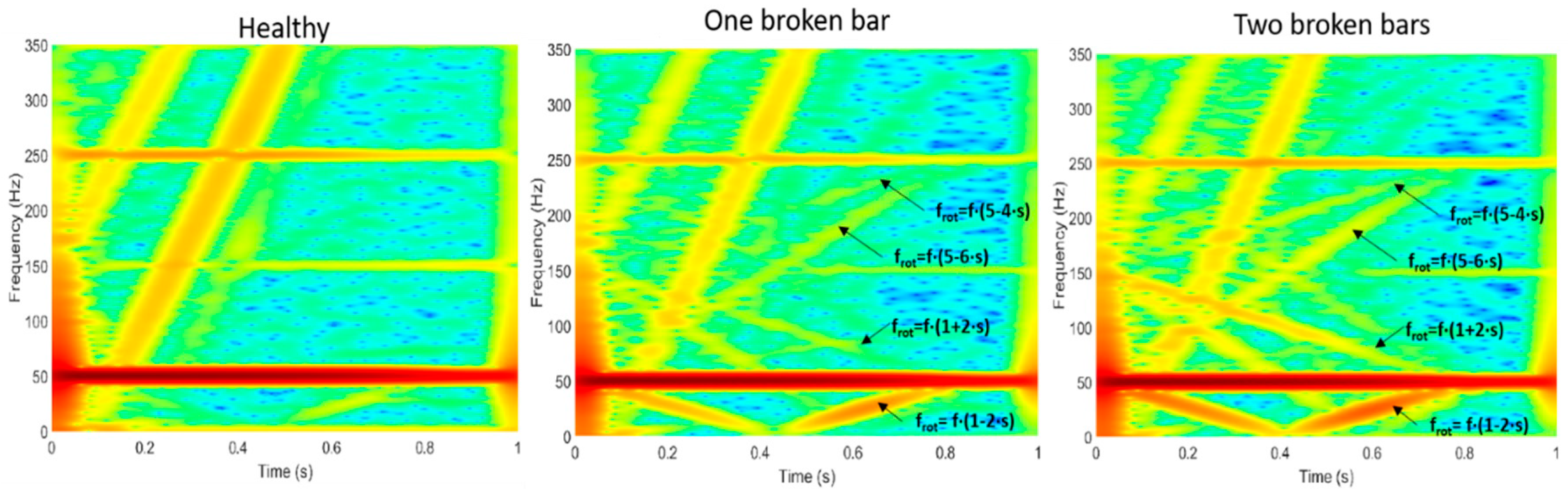
Figure 5 shows the time-frequency maps resulting from the application of the STFT to the starting current signals for three different fault conditions of the motor: healthy motor, motor with one broken bar, and motor with two broken rotor bars. All experiments were carried out at at Universitat Politecnica de Valencia, Valencia, Spain. Note the clear differences between all three maps; the evolutions of the fault harmonics are clearly evident for the faulty cases. In particular, the evolutions of the main sideband harmonics (f·(1 − 2·s) and f·(1 + 2·s)) are especially clear. In addition, the evolutions of higher-order rotor fault-related harmonics, such as f·(5 − 4·s) and f·(5 − 6·s), are clearly noticeable. These are clear indicators of the presence of the rotor damage. Finally, note how the intensity of the patterns created by the fault harmonic evolutions are higher when the level of rotor failure increases.
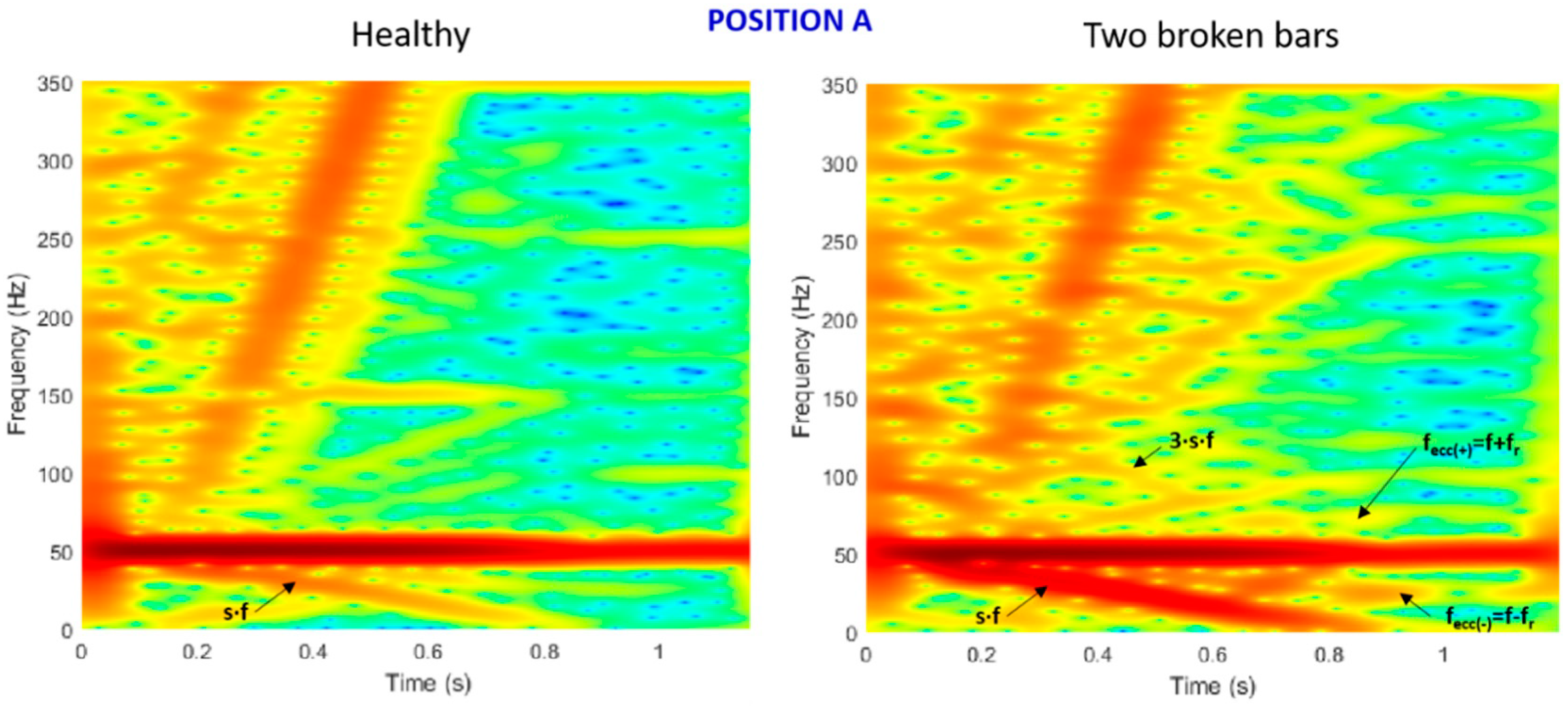
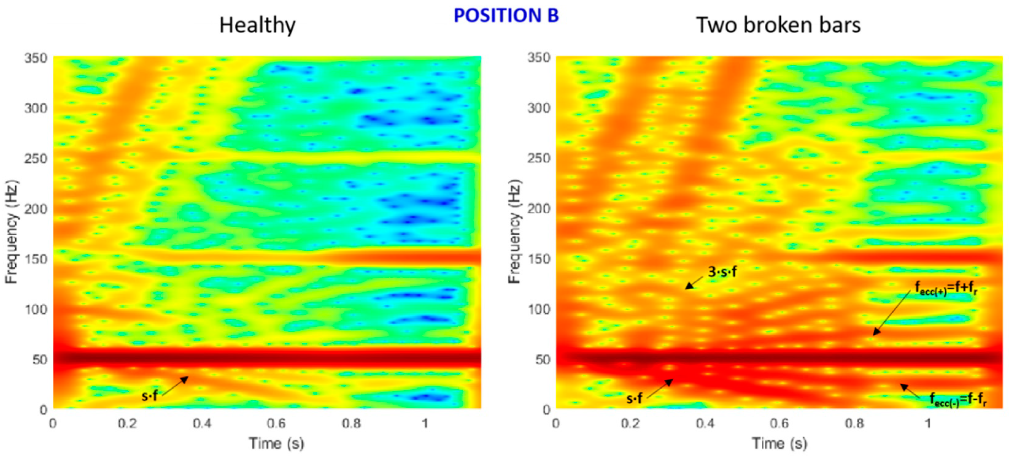
On the other hand, Figure 6 and Figure 7 show the time-frequency analyses of the stray flux signals under starting for the healthy motor and for the motor with two broken bars for two considered positions of the coil sensor: position A and position B. In comparison with Figure 5, note the much richer harmonic content of the stray flux maps depicted in Figure 6 and Figure 7. This illustrates an interesting advantage of stray flux analyses: since more evolutions can be identified in the time-frequency maps, the diagnosis will be more reliable, since it will rely on multiple harmonic evolutions rather than on evolutions of a few fault components. Moreover, note the clear differences between the healthy and faulty cases; much more harmonic evolutions are discernible in these latter cases. This is because the patterns caused by the evolutions of the fault harmonics are clearly amplified in these latter cases. More specifically, note the clear evolutions of the axial components, given by s·f and 3·s·f, that are amplified by the rotor damages. These components are already present in healthy condition (since they can be created by inherent eccentricities in the motor), but their respective amplitudes are clearly incremented when the fault is present. These components (that are not observed in the starting current analyses, see Figure 5) can be visualized in the graphs of Figure 6 and Figure 7 because these two sensor positions (position A and B) are those capturing a major portion of axial flux, as commented above (see Figure 3). On the contrary, note that the evolutions of the radial components such as f·(1 − 2·s) and f·(1 + 2·s) are less observable.
In conclusion, the time-frequency analyses of stray flux signals under starting yields time-frequency maps with higher harmonic content (hence with more potential for the diagnosis but also requiring a more complex interpretation) and with high sensitivity with respect to the sensor position since, according to the predominant portion of captured flux (axial/radial), the corresponding components can be better tracked. The determination of the optimum position of the flux sensor is a goal pursued in several works [28]. In this regard, position B shown in Figure 3 and Figure 4 seems to be a preferred option, since apart from being more accessible in practical applications (in comparison with other options), it captures both axial and radial flux and, therefore, a higher number of potential evolutions can be tracked in the analyses. Very recent papers have proposed the use of triaxial sensors to separately measure different stray flux portions in a single sensor [35].
4.2. Results in Field Motors
This section presents several examples of application of the electrical monitoring under transient conditions to diagnose the condition of field induction motors. All examples refer to starting current analysis.
4.2.1. Cage Motors in Water Intake Facility (3.8 MW, 6.6 kV)
Several High Voltage (H.V.) cage motors were diagnosed in a water intake facility [41]. To this end, starting current analyses were employed. The results revealed that all diagnosed motors had a certain level of damage in their rotor cages. However, the severity of the damage significantly changed from one motor to another. Figure 8 shows the time-frequency analyses for two of the diagnosed motors: while the motor A was diagnosed as healthy (no fault components evolutions were found in the time-frequency map), motor B was diagnosed with a severe level of rotor failure (see clear V-shaped pattern caused by the transient evolution of the f·(1 − 2·s) component). This latter motor was inspected in the repair shop and a significant number of broken bars were found in the rotor cage (more than 1/4 of the rotor bars were damaged) [41]. On the other hand, note how the time-frequency map for motor A shows a vertical line that is indicative of the commutation of the supply voltage under starting (the motor was started using an auto-transformer). This example clearly shows how the approach is highly reliable to detect rotor damages in cage motors.
4.2.2. Cage Motor in a Sewage Treatment Plant (30 kW, 400 V)
Several cage induction motors of a sewage treatment plant were diagnosed by applying the transient-based current methodology. Figure 9 depicts the time-frequency analyses for one of these motors (considering two different frequency ranges in the y-axis for a better visualization of the fault components). After a careful analysis of this map, it is observed that not only the components linked with rotor damages are present in that map (note the existence of the V-shaped pattern caused by the transient evolution of the f·(1 − 2·s) component), but also other evolutions corresponding to harmonics caused by other factors. In this regard, we note the presence of the evolutions linked with eccentricity components (fecc), as well as some other harmonics that are caused by problems in the coupling system (fcoupl). The presence of these harmonics enabled diagnosing, on the one hand, the existence of a slight eccentricity in the motor and, on the other hand, the presence of a certain level of degradation in the coupling system (which in this motor was based on gear reducers).
4.2.3. Wound Rotor Induction Motor in a Cement Plant (1.5 MW, 6.6 kV)
Figure 10 shows the time-frequency analyses (two graphs with different frequency ranges are shown in the y-axis for a better fault harmonic identification) corresponding to a H.V. wound rotor induction motor that was driving a ball mill in a cement production factory [42]. The motor was suspected to have a certain level of rotor winding asymmetry. Therefore, the starting current analysis was carried out in order to confirm this diagnostic. The maps shown in Figure 10 reveal a significant level of rotor winding asymmetry: the evolution of the lower sideband given by f·(1 − 2·s) is clearly evident. Moreover, other higher-order harmonics such as the upper sideband (f·(1 + 2·s)) are also present. All these evidences led to diagnosing a severe level of rotor winding asymmetry. As a consequence, the rotor winding was inspected, and a deficient contact was found between the slip rings/brushes system of one phase [42], which was causing the asymmetry. This problem, which could have had very negative repercussions for the company, was properly detected and corrected thanks to the application of the starting current analysis.
5. Conclusions
This paper has been intended to provide an overview of electrical monitoring under transient conditions, which is a new approach that is drawing the attention of many researchers and companies in the electric motors condition monitoring area.
Unlike the classical fault diagnosis methods that are based on the analysis of electrical quantities under steady-state operation of the motor by applying conventional signal processing tools, the new condition monitoring philosophy relies on registering the corresponding electrical quantity (i.e., current or flux) under transient operation of the machine (e.g., under starting) and analyzing it using time-frequency transforms. The ultimate objective is to identify, in the time-frequency maps resulting from these transforms, the characteristic patterns caused by the evolutions of fault-related components during the considered transient. It has been proven that these patterns are reliable ‘signatures’ of the fault, since they are very unlikely caused by other phenomena that do not correspond to the failure. This fact enables avoiding false indications that are typical not only of classical electrical-based techniques but also of other predictive maintenance methods (e.g., vibration data analysis). These statements are proven by the results obtained during these last years in a wide range of motors in which the transient-based techniques have proven their accuracy regardless of the constructive characteristics of the machine (e.g., presence of rotor cooling ducts, double cage rotors, rotor magnetic anisotropy…) and of its operating conditions (e.g., reduced slip operation, presence of load torque oscillations, blade pass vibrational frequencies due to the load…).
The paper has shown the main foundations and underlying ideas of the transient-based analysis of electrical quantities, emphasizing its advantages versus classical methods. Moreover, it has brought several examples, which referred to both laboratory and industrial motors (of different typology) that illustrate how the methodology is applied.
Today, one of the most dynamic research lines is focused on the automatic identification of the fault patterns arising in the time-frequency maps resulting from the application of the transforms. In this regard, modern investigations are making use of artificial intelligence methods and pattern recognition algorithms to automatically identify the mentioned patterns, hence avoiding the necessity of user intervention. The development and optimization of these algorithms increases the possibility of implementing these technologies in portable condition monitoring devices or autonomous diagnostic systems that enable obtaining a direct diagnosis of the motor condition. The implementation of these expert systems in smart sensors is also a hot topic in the area [35]. The paper content may be of interest for researchers involved in the electric motors predictive maintenance area who want to be aware of the potential of this new technology that is expected to have a strong penetration in industry during the coming years.
Funding
This research was funded by by the Spanish ‘Ministerio de Ciencia Innovación y Universidades’ and FEDER program in the framework of the ‘Proyectos de I + D de Generación de Conocimiento del Programa Estatal de Generación de Conocimiento y Fortalecimiento Científico y Tecnológico del Sistema de I + D + i, Subprograma Estatal de Generación de Conocimiento’ (ref: PGC2018-095747-B-I00).
Conflicts of Interest
The authors declare no conflict of interest.
Nomenclature
| CWD | Choi-Williams Distributions |
| CWT | Continuous Wavelet Transform |
| DWT | Discrete Wavelet Transform |
| HHT | Hilbert-Huang Transform |
| LSH | Lower Sideband Harmonic |
| MCSA | Motor Current Signature Analysis |
| STFT | Short Time Fourier Transform |
| UDWT | Undecimated Discrete Wavelet Transform |
| USH | Upper Sideband Harmonic |
| VSD | Variable Speed Drive |
| WP | Wavelet Packets |
| WVD | Wigner-Ville Distribution |
References
- De la Morena, J. Eficiencia energética en motores eléctricos. Normativa IEC 60034-30. In Proceedings of the II Congreso de Eficiencia Energética, Madrid, Spain, 23–26 October 2012. [Google Scholar]
- Electric Motor Engineering. Available online: https://www.electricmotorengineering.com/a-global-electric-motor-market-overview/ (accessed on 10 August 2020).
- Antonino-Daviu, J.; Fuster-Roig, V.; Park, S.; Park, Y.; Choi, H.; Park, J.; Lee, S.B. Electrical Monitoring of Damper Bar Condition in Salient-Pole Synchronous Motors Without Motor Disassembly. IEEE Trans. Ind. Appl. 2020, 56, 1423–1431. [Google Scholar] [CrossRef]
- Garcia, M.; Panagiotou, P.; Antonino-Daviu, J.; Gyftakis, K.N. Efficiency Assessment of Induction Motors Operating Under Different Faulty Conditions. IEEE Trans. Ind. Electron. 2019, 66, 8072–8081. [Google Scholar] [CrossRef]
- Nandi, S.; Toliyat, H.A.; Li, X. Condition monitoring and fault diagnosis of electrical motors—A review. IEEE Trans. Energy Convers. 2005, 20, 719–729. [Google Scholar] [CrossRef]
- Thomson, W.T.; Culbert, I. Current Signature Analysis for Condition Monitoring of Cage Induction Motors: Industrial Application and Case Histories; John Wiley & Sons: Hoboken, NJ, USA, 2017. [Google Scholar]
- Antonino-Daviu, J.A.; Quijano-López, A.; Rubbiolo, M.; Climente-Alarcon, V. Advanced Analysis of Motor Currents for the Diagnosis of the Rotor Condition in Electric Motors Operating in Mining Facilities. IEEE Trans. Ind. Appl. 2018, 54, 3934–3942. [Google Scholar] [CrossRef]
- Antonino-Daviu, J.A.; Pons-Llinares, J.; Lee, S.B. Advanced rotor fault diagnosis for medium-voltage induction motors via continuous transforms. IEEE Trans. Ind. Appl. 2016, 52, 4503–4509. [Google Scholar] [CrossRef]
- Lee, S.B.; Stone, G.; Antonino-Daviu, J.; Gyftakis, K.N.; Strangas, E.G.; Maussion, P.; Platero, C.A. Recent Challenges in Condition Monitoring of Industrial Electric Machines. IEEE Ind. Electron. Mag. 2020, in press. [Google Scholar]
- Antonino-Daviu, J.A.; Riera-Guasp, M.; Roger Folch, J.; Molina-Palomares, M.P. Validation of a new method for the diagnosis of rotor bar failures via wavelet transform in industrial induction machines. IEEE Trans. Ind. Appl. 2006, 42, 990–996. [Google Scholar] [CrossRef]
- Schoen, R.R.; Habetler, T.G. Evaluation and implementation of a system to eliminate arbitrary load effects in current-based monitoring of induction machines. IEEE Trans. Ind. Appl. 1997, 33, 1571–1577. [Google Scholar] [CrossRef]
- Lee, S.; Hong, J.; Lee, S.B.; Wiedenbrug, E.J.; Teska, M.; Kim, H. Evaluation of the Influence of Rotor Axial Air Ducts on Condition Monitoring of Induction Motors. IEEE Trans. Ind. Appl. 2013, 49, 2024–2033. [Google Scholar] [CrossRef]
- Yang, C.; Kang, T.; Hyun, D.; Lee, S.B.; Antonino-Daviu, J.A.; Pons-Llinares, J. Reliable Detection of Induction Motor Rotor Faults Under the Rotor Axial Air Duct Influence. IEEE Trans. Ind. Appl. 2014, 50, 2493–2502. [Google Scholar] [CrossRef]
- Antonino-Daviu, J.A.; Pons-Llinares, J.; Shin, S.; Lee, K.W.; Lee, S.B. Reliable detection of induction motor rotor faults under the influence of rotor core magnetic anisotropy. In Proceedings of the IEEE 10th International Symposium on Diagnostics for Electrical Machines, Power Electronics and Drives (SDEMPED 2015), Guarda, Portugal, 1–4 September 2015; pp. 14–21. [Google Scholar]
- Park, Y.; Jeong, M.; Lee, S.B.; Antonino-Daviu, J.A.; Teska, M. Influence of Blade Pass Frequency Vibrations on MCSA-Based Rotor Fault Detection of Induction Motors. IEEE Trans. Ind. Appl. 2017, 53, 2049–2058. [Google Scholar] [CrossRef]
- Riera-Guasp, M.; Cabanas, M.F.; Antonino-Daviu, J.A.; Pineda-Sánchez, M.; García, C.H.R. Influence of Nonconsecutive Bar Breakages in Motor Current Signature Analysis for the Diagnosis of Rotor Faults in Induction Motors. IEEE Trans. Energy Convers. 2010, 25, 80–89. [Google Scholar] [CrossRef]
- Antonino-Daviu, J.; Riera-Guasp, M.; Pons-Llinares, J.; Park, J.; Lee, S.B.; Yoo, J.; Kral, C. Detection of Broken Outer-Cage Bars for Double-Cage Induction Motors Under the Startup Transient. IEEE Trans. Ind. Appl. 2012, 48, 1539–1548. [Google Scholar] [CrossRef]
- Lee, S.B.; Wiedenbrug, E.; Younsi, K. Testing and Diagnostics of Induction Machines in an Industrial Environment; ECCE 2013 Tutorial; IEEE Industry Applications Society: Denver, CO, USA, 2013. [Google Scholar]
- Antonino-Daviu, J.; Jover, P.; Riera-Guasp, M.; Roger-Folch, J.; Arkkio, A. DWT Analysis of Numerical and Experimental Data for the Diagnosis of Dynamic Eccentricities in Induction Motors. Mech. Syst. Signal Process. 2007, 21, 2575–2589. [Google Scholar] [CrossRef]
- Picot, A.; Fournier, E.; Régnier, J.; Tientcheu Yamdeu, M.; Andréjak, J.; Maussion, P. Statistic-Based Method to Monitor Belt Transmission Looseness through Motor Phase Current. IEEE Trans. Ind. Inform. 2017, 13, 1332–1340. [Google Scholar] [CrossRef] [Green Version]
- Antonino-Daviu, J.; Pons-Llinares, J.; Climente-Alarcon, V.; Razik, H. Evaluation of startup-based rotor fault severity indicators under different starting methods. In Proceedings of the 40th Annual Conference of the IEEE Industrial Electronics Society (IECON 2014), Dallas, TX, USA, 29 October–1 November 2014. [Google Scholar]
- Corral Hernandez, J.; Antonino-Daviu, J.A.; Climente-Alarcon, V.; Pons-Llinares, J.; Frances-Galiana, V. Transient-based rotor cage assessment in induction motors operating with soft-starters. IEEE Trans. Ind. Appl. 2015, 51, 3734–3742. [Google Scholar] [CrossRef]
- Pons-Llinares, J.; Antonino-Daviu, J.; Roger-Folch, J.; Moríñigo-Sotelo, D.; Duque-Pérez, O. Mixed eccentricity diagnosis in Inverter-Fed Induction Motors via the Adaptive Slope Transform of transient stator currents. Mech. Syst. Signal Process. 2014, 48, 426–435. [Google Scholar] [CrossRef]
- Pons-Llinares, J.; Moriñigo-Sotelo, D.; Duque-Perez, O.; Antonino-Daviu, J.; Pérez-Alonso, M. Transient Detection of Close Components through the Chirplet Transform: Rotor Faults in Inverter-Fed Induction Motors. In Proceedings of the 40th Annual Conference of the IEEE Industrial Electronics Society (IECON 2014), Dallas, TX, USA, 29 October–1 November 2014. [Google Scholar]
- Henao, H.; Demian, C.; Capolino, G.A. A Frequency Domain Detection of Faults in Induction Machines Using an External Flux Sensor. IEEE Trans. Ind. Appl. 2003, 39, 1272–1279. [Google Scholar] [CrossRef]
- Bellini, A.; Concari, C.; Franceschini, G.; Tassoni, C.; Toscani, A. Vibrations, currents and stray flux signals to asses induction motors rotor conditions. In Proceedings of the IECON 2006—32nd Annual Conference on IEEE Industrial Electronics, Paris, France, 6–10 November 2006; pp. 4963–4968. [Google Scholar]
- Frosini, L.; Borin, A.; Girometta, L.; Venchi, G. A novel approach to detect short circuits in low voltage induction motor by stray flux measurement. In Proceedings of the International Conference on Electrical Machines (ICEM 2012), Marseille, France, 2–5 September 2012; pp. 1538–1544. [Google Scholar]
- Ramirez-Nunez, J.A.; Antonino-Daviu, J.A.; Climente-Alarcón, V.; Quijano-Lopez, A.; Razik, H.; Osornio-Rios, R.A.; Romero-Troncoso, R.D. Evaluation of the Detectability of Electromechanical Faults in Induction Motors Via Transient Analysis of the Stray Flux. IEEE Trans. Ind. Appl. 2018, 54, 4324–4332. [Google Scholar] [CrossRef]
- Zamudio-Ramirez, I.; Antonino-Daviu, J.A.; Osornio-Rios, R.A.; de Romero-Troncoso, R.J.; Razik, H. Detection of Winding Asymmetries in Wound-Rotor Induction Motors via Transient Analysis of the External Magnetic Field. IEEE Trans. Ind. Electron. 2020, 67, 5050–5059. [Google Scholar] [CrossRef]
- Park, Y.; Choi, H.; Shin, J.; Park, J.; Lee, S.B.; Jo, H. Airgap Flux based Detection and Classification of Induction Motor Rotor and Load Defects during the Starting Transient. IEEE Trans. Ind. Electron. 2020, in press. [Google Scholar] [CrossRef]
- Gyftakis, K.N.; Panagiotou, P.A.; Lee, S.B. Generation of Mechanical Frequency Related Harmonics in the Stray Flux Spectra of Induction Motors Suffering from Rotor Electrical Faults. IEEE Trans. Ind. Appl. 2020, in press. [Google Scholar]
- Park, Y.; Yang, C.; Kim, J.; Kim, H.; Lee, S.B.; Gyftakis, K.N.; Panagiotou, P.A.; Kia, S.H.; Capolino, G.A. Stray Flux Monitoring for Reliable Detection of Rotor Faults Under the Influence of Rotor Axial Air Ducts. IEEE Trans. Ind. Electron. 2019, 66, 7561–7570. [Google Scholar] [CrossRef]
- ABB. ABB Ability Smart Sensor for Motors. Available online: https://new.abb.com/motors-generators/service/advanced-services/smart-sensor/smart-sensor-for-motors (accessed on 10 August 2020).
- WEG Motor Group. WEG Motor Scan—Whitepaper. Available online: https://www.weg.net/wegmotorscan/en (accessed on 10 August 2020).
- Zamudio-Ramírez, I.; Osornio-Rios, R.A.; Antonino-Daviu, J.A. Triaxial Smart Sensor Based on the Advanced Analysis of Stray Flux and Currents for the Reliable Fault Detection in Induction Motors. In Proceedings of the 12th IEEE Energy Conversion Congress and Exposition (ECCE 2020), Detroit, MI, USA, 11–15 October 2020. [Google Scholar]
- Ceban, A.; Pusca, R.; Romary, R. Study of Rotor Faults in Induction Motors Using External Magnetic Field Analysis. IEEE Trans. Ind. Electron. 2012, 59, 2082–2093. [Google Scholar] [CrossRef]
- Romary, R.; Pusca, R.; Lecointe, J.P.; Brudny, J.F. Electrical Machines Fault Diagnosis by Stray Flux Analysis. In Proceedings of the 2013 IEEE Workshop on Electrical Machines Design, Control and Diagnosis (WEMDCD), Paris, France, 11–12 March 2013; pp. 247–256. [Google Scholar]
- Ishkova, L.; Vitek, O. Detection and classification of faults in induction motor by means of motor current signature analysis and stray flux monitoring. Prz. Elektrotechniczny 2016, 92, 166–170. [Google Scholar] [CrossRef] [Green Version]
- Antonino-Daviu, J.; Zamudio-Ramírez, I.; Osornio-Ríos, R.A.; Fuster-Roig, V.; de Jesús Romero-Troncoso, R.; Dunai, L.D. Stray Flux Analysis for the Detection of Rotor Failures in Wound Rotor Induction Motors. In Proceedings of the 45th Annual Conference of the IEEE Industrial Electronics Society (IECON 2019), Lisbon, Portugal, 14–17 October 2019. [Google Scholar]
- Pons-Llinares, J.; Antonino-Daviu, J.A.; Riera-Guasp, M.; Lee, S.B.; Kang, T.-J.; Yang, C. Advanced Induction Motor Rotor Fault Diagnosis via Continuous and Discrete Time–Frequency Tools. IEEE Trans. Ind. Electron. 2015, 62, 1791–1802. [Google Scholar] [CrossRef]
- Antonino-Daviu, J.A.; Lee, S.B.; Wiedenbrug, E. Reliable detection of rotor bar failures in induction motors operating in petrochemical plants. In Proceedings of the 11th Petroleum and Chemical Industry Conference Europe (PCIC Europe 2014), Amsterdam, The Netherlands, 3–5 June 2014. [Google Scholar]
- Antonino-Daviu, J.A.; Quijano-Lopez, A.; Climente-Alarcon, V.; Garín-Abellán, C. Reliable Detection of Rotor Winding Asymmetries in Wound Rotor Induction Motors via Integral Current Analysis. IEEE Trans. Ind. Appl. 2017, 53, 2040–2048. [Google Scholar] [CrossRef]
Figure 1.
Recent trend in the electric motors condition monitoring area based on the integration of the monitoring of different motor quantities for the development of intelligent diagnostic systems.
Figure 1.
Recent trend in the electric motors condition monitoring area based on the integration of the monitoring of different motor quantities for the development of intelligent diagnostic systems.

Figure 2.
Theoretical evolutions of the most relevant harmonics associated to rotor damages (denoted by frot) and eccentricities/misalignments (denoted by fecc) that are present in the motor starting current, considering a simulated direct on-line starting on an induction motor.
Figure 2.
Theoretical evolutions of the most relevant harmonics associated to rotor damages (denoted by frot) and eccentricities/misalignments (denoted by fecc) that are present in the motor starting current, considering a simulated direct on-line starting on an induction motor.


Figure 4.
Experimental test bench and two considered positions of the flux sensor [28].
Figure 4.
Experimental test bench and two considered positions of the flux sensor [28].

Figure 5.
Time-frequency maps of the starting current for different rotor fault conditions.

Figure 6.
Time-frequency maps of the electromotive force (emf) signals induced by the stray flux at sensor position A for the two considered fault conditions.
Figure 6.
Time-frequency maps of the electromotive force (emf) signals induced by the stray flux at sensor position A for the two considered fault conditions.

Figure 7.
Time-frequency maps of the emf signals induced by the stray flux at sensor position B for the two considered fault conditions.
Figure 7.
Time-frequency maps of the emf signals induced by the stray flux at sensor position B for the two considered fault conditions.

Figure 8.
Time-frequency maps of the starting current for two H.V. cage motors of the water intake facility.
Figure 8.
Time-frequency maps of the starting current for two H.V. cage motors of the water intake facility.

Figure 9.
Time-frequency maps of the starting current for a Low Voltage (L.V.) cage motor of the sewage treatment plant.
Figure 9.
Time-frequency maps of the starting current for a Low Voltage (L.V.) cage motor of the sewage treatment plant.

Figure 10.
Time-frequency maps of the starting current for a H.V. wound rotor induction motor of a cement plant.
Figure 10.
Time-frequency maps of the starting current for a H.V. wound rotor induction motor of a cement plant.


Table 1.
Comparison between the diagnostic conclusion provided by Motor Current Signature Analysis (MCSA) and the real machine condition: sources of possible false positive and false negative indications.
Table 1.
Comparison between the diagnostic conclusion provided by Motor Current Signature Analysis (MCSA) and the real machine condition: sources of possible false positive and false negative indications.
| Real Machine Condition | Diagnostic Conclusion MCSA | |
|---|---|---|
| Healthy | Faulty | |
| Healthy | CORRECT | FALSE POSITIVE: |
| Faulty | FALSE NEGATIVE: | CORRECT |
Table 2.
Main time-frequency tools for the application of transient-based diagnosis approaches [40]. CWD: Choi–Williams Distributions; CWT: Continuous Wavelet Transform; DWT: Discrete Wavelet Transform; HHT: Hilbert–Huang Transform; UDWT: Undecimated Discrete Wavelet Transform; WP: Wavelet Packets.
Table 2.
Main time-frequency tools for the application of transient-based diagnosis approaches [40]. CWD: Choi–Williams Distributions; CWT: Continuous Wavelet Transform; DWT: Discrete Wavelet Transform; HHT: Hilbert–Huang Transform; UDWT: Undecimated Discrete Wavelet Transform; WP: Wavelet Packets.
| Type of t-f Tool | Advantages | Drawbacks | Examples |
|---|---|---|---|
| Discrete |
|
| DWT, UDWT, WP |
| Continuous |
|
| CWT, HHT, WVD, CWD |
© 2020 by the author. Licensee MDPI, Basel, Switzerland. This article is an open access article distributed under the terms and conditions of the Creative Commons Attribution (CC BY) license (http://creativecommons.org/licenses/by/4.0/).
Share and Cite
MDPI and ACS Style
Antonino-Daviu, J. Electrical Monitoring under Transient Conditions: A New Paradigm in Electric Motors Predictive Maintenance. Appl. Sci. 2020, 10, 6137. https://0-doi-org.brum.beds.ac.uk/10.3390/app10176137
AMA Style
Antonino-Daviu J. Electrical Monitoring under Transient Conditions: A New Paradigm in Electric Motors Predictive Maintenance. Applied Sciences. 2020; 10(17):6137. https://0-doi-org.brum.beds.ac.uk/10.3390/app10176137
Chicago/Turabian StyleAntonino-Daviu, Jose. 2020. "Electrical Monitoring under Transient Conditions: A New Paradigm in Electric Motors Predictive Maintenance" Applied Sciences 10, no. 17: 6137. https://0-doi-org.brum.beds.ac.uk/10.3390/app10176137
Note that from the first issue of 2016, this journal uses article numbers instead of page numbers. See further details here.