Model Test and Numerical Simulation of Single Pile Response under Combined Loading in Slope


1
School of Civil Engineering and Architecture, Henan University, Kaifeng 475004, China
2
Institute of Geotechnical and Rail Transport Engineering, Henan University, Kaifeng 475004, China
3
College of Science, Engineering of Flinders University, Adelaide 5042, Australia
*
Author to whom correspondence should be addressed.
Appl. Sci. 2020, 10(17), 6140; https://0-doi-org.brum.beds.ac.uk/10.3390/app10176140
Submission received: 3 August 2020
/
Revised: 23 August 2020
/
Accepted: 2 September 2020
/
Published: 3 September 2020
(This article belongs to the Special Issue Advances in Geotechnical Engineering)
Abstract
:Vertical loads are commonly transferred by piles primarily in the upper structures. However, lateral loads are also significant compared with vertical loads in pile foundation design. Compared with a pile on level ground, there are many particular characteristics in a pile that is on sloping ground. These characteristics depend on the combined loading and the magnitude of the soil lateral displacement. In order to investigate the pile’s bearing characteristics, a model test was conducted and ABAQUS software was adopted to conduct 3D numerical simulation of a single pile with different slope angles under combined loads. The experimental results indicated that (1) the soil pressure along the slope direction was smaller than the other side, resulting in an asymmetry of the slope soil around the pile, and in turn introducing a horizontal thrust to the pile; (2) with the increase of slope angle, the horizontal thrust increased while the single pile’s bearing capacity decreased; (3) the vertical load caused more pile horizontal displacement with the growth of slope angle; and (4) the pile’s moment and the displacement also increased with the growth of the slope angle. The findings in this study can provide a useful reference in the design of piles or anti-slide piles in sloping ground.
1. Introduction
Pile foundations have been used for several years in bridge and building engineering to support lateral and vertical loads. Some projects, such as bridges, accommodation projects, and others located in complex terrain and landforms typically set piles in sloping ground to reduce the amount of earthwork required. These pile foundations are affected by both the upper vertical and lateral loads as well as the pile-side landslide thrust. As a result, their formation mechanism, load distribution, and horizontal resistance influenced by the lateral soil are highly complex [1,2,3,4], and the soil–structure interaction is also very important [5,6,7,8]. Furthermore, the pile foundation requires different bearing performances when it is located on slopes with different angles [9].
An early study on a single pile was mainly aimed at the estimation of ultimate bearing capacity. Broms [10] assumed the lateral pile-soil pressure’s distribution and then used statistical analysis as an approximate solution for the single pile’s ultimate lateral resistance. Randolph [11] put forward a 2D Finite Element Method (FEM) solution that modelled the soil and the pile as an elastic continuum and elastic beam, respectively. To overcome the limitations of 2D methods, many attempts were made to perform the pile under combined loading by converting 2D to 3D cases based on FEM. Fan and Long [12] modelled the soil and the pile as elastic–plastic material and linear–elastic material, respectively, then introduced 3D FEM analysis method for laterally-loaded piles in soil. Chik et al. [13] developed this further with the introduction of PLAXIS software; moreover, the Mohr–Coulomb elastoplastic model was used for the soil model.
In recent years, many analytical methods for the response analysis of piles have been developed under combined loads. Comodromos et al. [14] presented a simple method for designing a pile foundation under combined loading. Begum and Muthukkumaran [15] achieved the research of laterally-loaded piles on a sloped surface through changing the slope angle and the relative density of the soil. Chien et al. [16] reported the full-scale shaft load tests with axial load or lateral load only. It could be seen from the test results that 63% of the pile head displacement produced a combined load corresponding to the lateral load under the same lateral load. Xie et al. [17] performed tests on a single pile located at different positions on the slope with horizontal loading as well as unloading, which concluded that the pile strain was reduced as the distance from the slope increased. Zhang et al. [18] simulated the pile load and deformation with the combined effect of the slope’s vertical and horizontal loads. The study pointed out that the vertical load could effectively make the pile’s bending moment and lateral displacement decrease under combined force. Kershaw and Luna [19] explored some combined-load field tests by applying a static axial and lateral load on the micropiles. The concrete-embedded strain gauges were used to measure the distribution of load and pile-head, load-deformation response and bending moment with depth along the micropile length. Zuo et al. [20] analyzed the force on an all-straight pile foundation under the action of a two-way cyclic load, which illustrated that the force on a pile became redistributed, and the pile body axial force increased gradually while the side friction resistance decreased with the combined action of horizontal and vertical cyclic loading. Muthukkumaran and Begum [21] studied the p–y curves of the slope, the embedded depth of the pile, and the soil’s density by using laboratory experiments. It revealed that the soil resistance increased with the pile’s buried length and the growth of soil density. Jegatheeswaran and Muthukkumaran [22] explored the pile’s horizontal displacement by examining the vertical and horizontal loads on the pile foundation from different angles.
The previous studies, mentioned above, investigated the relationship between the pile-soil failure mode and the pile-soil system’s stiffness in the plane. However, there is little research on the failure mode of lateral load piles on slopes. The passive soil pressure area of the lateral load pile on the slope is smaller than that of the pile in the ground, which will affect the displacement and the pile’s bending moment, thereby affecting the structural design of the pile. Therefore, it is necessary to deeply research the piles’ bending moment and lateral displacement for varying slope angles. In this paper, model tests and ABAQUS FE analysis software were used to analyze the distribution of soil pressure around piles, the difference of pile head displacement under different loads, and the variation of internal force of pile on different slopes.
2. Model Test
2.1. Pile and Soil Model
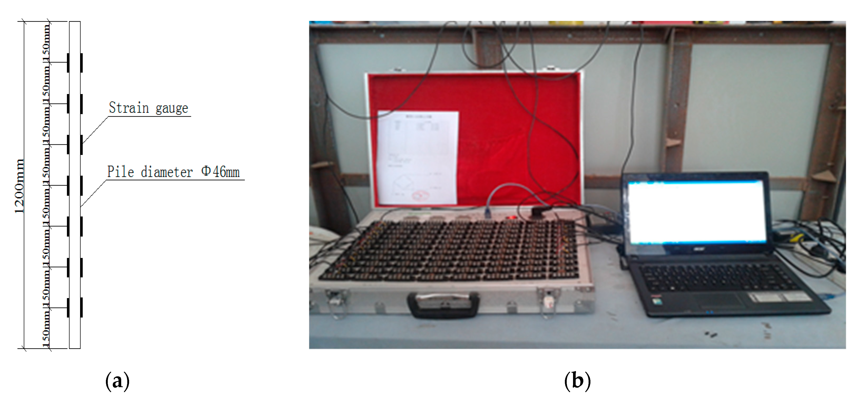
This paper’s model pile was a precast reinforced concrete circular pile, with a length of 1200 mm, and diameter of 46 mm. The mixing ratio of cement: fine aggregate: coarse aggregate was 1:1.84:2.49 was adopted for casting the specimens, and the water: cement ratio was 0.6. The concrete cube’s compressive strength was 22.5 N/mm2 after 28 days’ curing time. As indicated in Figure 1a, there were fourteen strain gauges on the model pile, which was parallel to the pile axis and directly opposite each other at seven levels along the model pile shaft. The epoxy resin was used to protect the surface of the strain gauge, and it could also prevent the strain gauge on the pile from falling off during the process of loading and embedding [21]. For measuring the strain of the pile multi-point static strain gauges (model: CM2B) were used (shown in Figure 1b).
Generally, according to the effective zone of soil mass at the edge of the foundation, the model test tank’s dimensions could be determined. It could be deduced that the boundary effect was more significant in the range of 10 times the pile diameter from the pile circumference for the single pile with the lateral load [23,24,25]. A rectangle steel tank made of high strength steel plate was used as the test tank in this study, with a size of 4 m × 2 m × 2 m. A length of 1 m (20 d) was the minimum distance between the tank and the pile. The boundary effect around the horizontal displacement of the pile could be eliminated. The model tank included two parts: (1) two holes for draining the silt, and (2) two supports consisting of H-beams made of 12 mm thick steel plates for setting the reaction frame.
It was essential to prepare the test samples in laboratory model pile tests because the piles’ characteristics were closely correlated with the soil sample [26]. The test soil was taken from Kaifeng sand. The sample silts were filled into every 15 cm layer in the model tank and then compacted. The soil sample’s physical and mechanical parameters can be seen in Table 1.
2.2. Test Apparatus
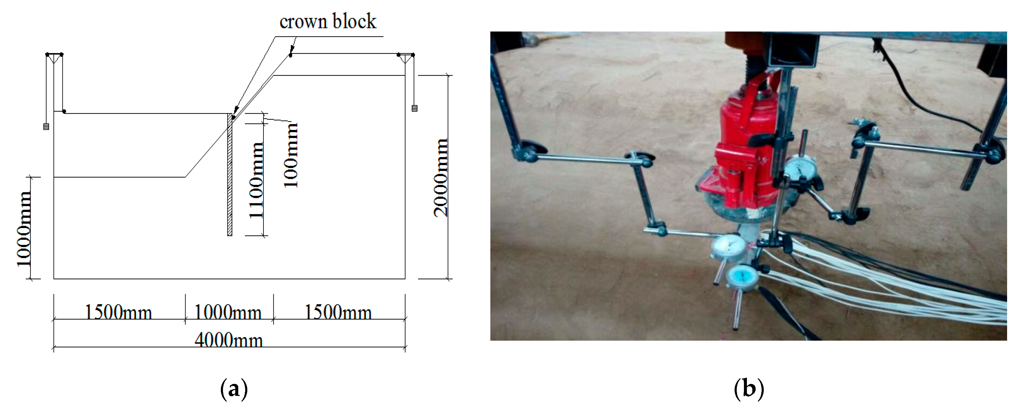
In order to apply the bending moment and combined load to the single pile at the slope, a loading system was designed by the research group. A hydraulic jack would support the vertical load, and the load which was applied at each level was determined by using the type pressure sensor (minimum range of 0.1 kg). The wire rope provided the horizontal load and the bending moment through the pulley fixed in the model slot. The load of the horizontal load could be kept level by adjusting the pulley position. The layout of the loading system is shown in Figure 2a. Two dial gauges were installed at the pile top and the junction of the soil and pile to measure the horizontal displacement, respectively. The distance between the two dial gauges was 30 mm. Figure 2b shows the layout of the two dial gauges.
2.3. Experimental Process
The loading sequence was vertical load, bending moment, and horizontal load in this test. The test load adopted a slow-speed maintenance method. Firstly, the vertical load was applied, and the load of each level was the same (100 N). When the settlement rate stabilized and met the specifications required, the next level was applied. The vertical load remains unchanged after reaching the design value. The test then used the self-made horizontal loading system to apply a 15 N·m bending moment load at the pile top. Then, the pile’s displacement was stable, the stage horizontal load was applied. After each step of the lateral load being applied, the dial gauge was observed every 30 min. If the dial gauge reading change was less than 0.01 mm, it was considered stable. The dial gauge readings were recorded and the pile displacement was saved; the next stage load was then applied.
3. Test Results Analysis
This article conducted three experiments on the same pile, and the experimental results were basically the same, choosing one of the better experimental results for analysis. The test data included the pile top’s bending moment and the horizontal displacement under the vertical bending moment. The strain was measured using the strain gauge.
3.1. Displacement and Horizontal Load
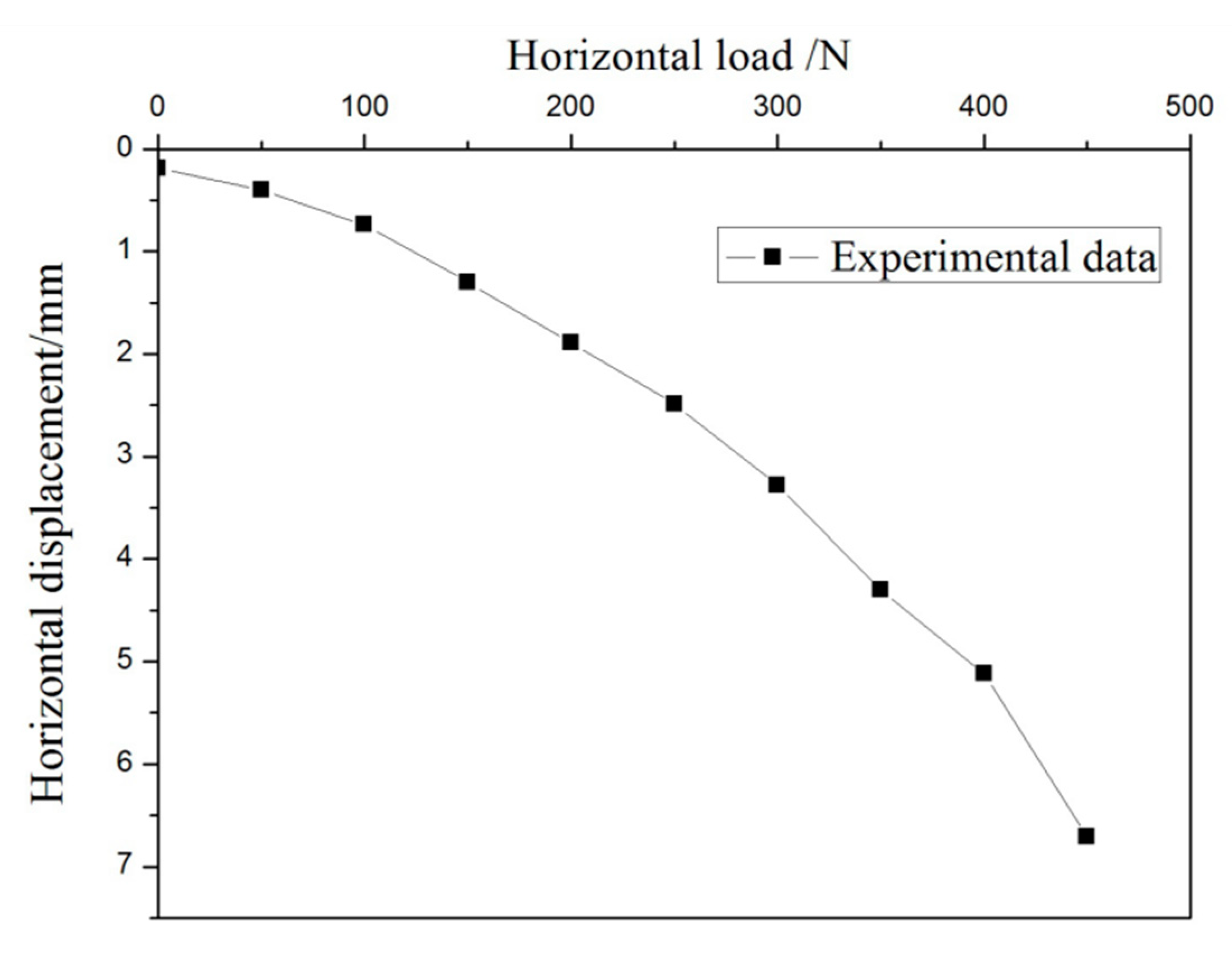
The curve of load–displacement is shown in Figure 3. Because of the soil pressure load on the slope, the horizontal displacement of 0.19 mm was produced before the pile was subjected to horizontal load. As the lateral load increased to 450 kN, the displacement reached 6.71 mm. The pile’s horizontal displacement was small at the beginning of loading. With the growth of the load, the soil around the pile had plastic damage. The horizontal displacement increased significantly.
3.2. Bending Moment of the Pile
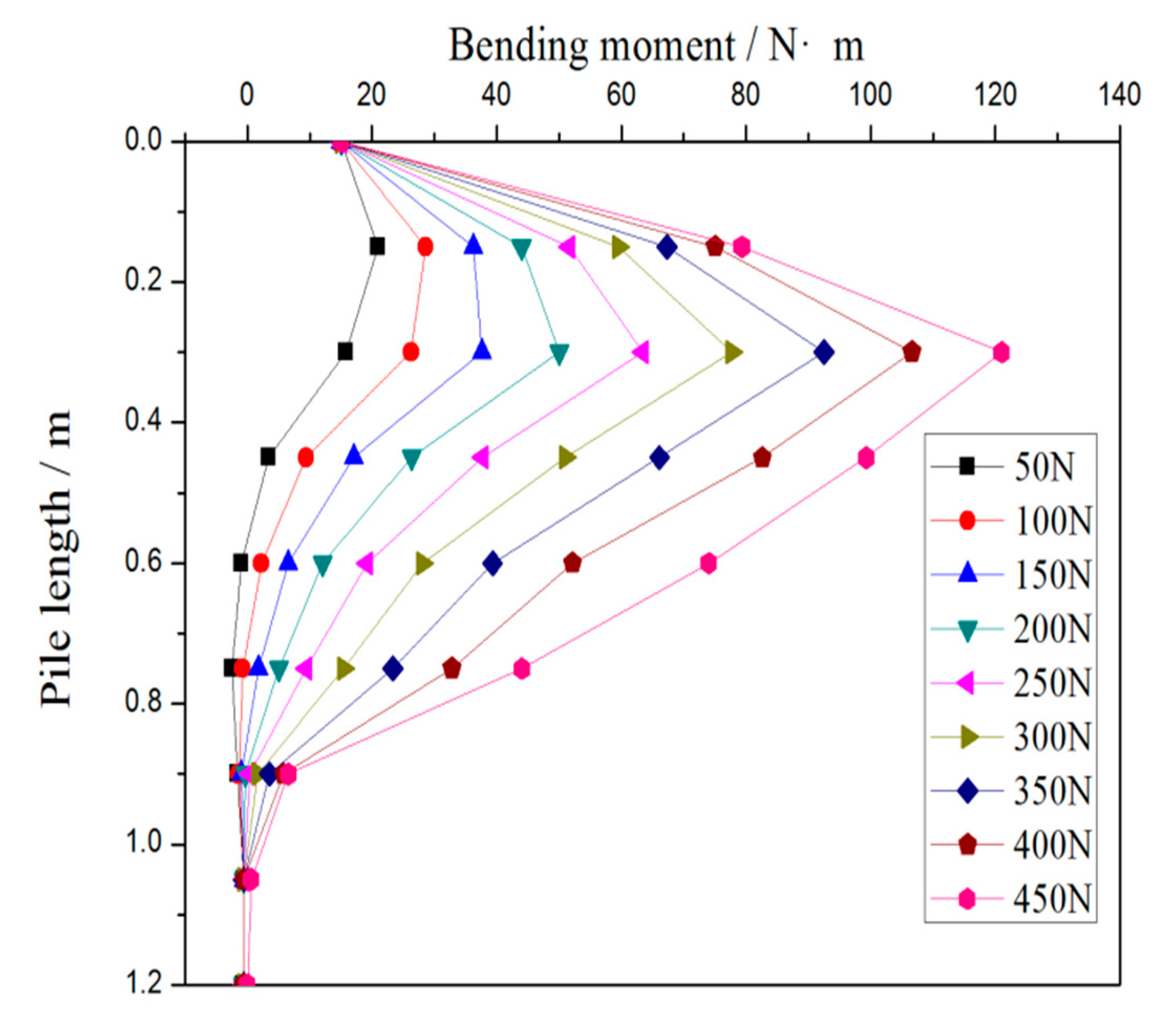
Figure 4 describes the pile’s bending moment under different lateral loads. Owing to soil pressure load on the slope, the pile top’s initial bending moment was 15 N·m. When the horizontal load was small, the pile’s maximum bending moment was in section 0.2 m (four times the pile diameter). When the horizontal load increased, the pile’s maximum bending moment moved down the section 0.3 m (six times the pile diameter). This indicated that when horizontal load increased, the effect of load depth also increased.
4. 3D FEM Formulation
4.1. Numerical Model Size
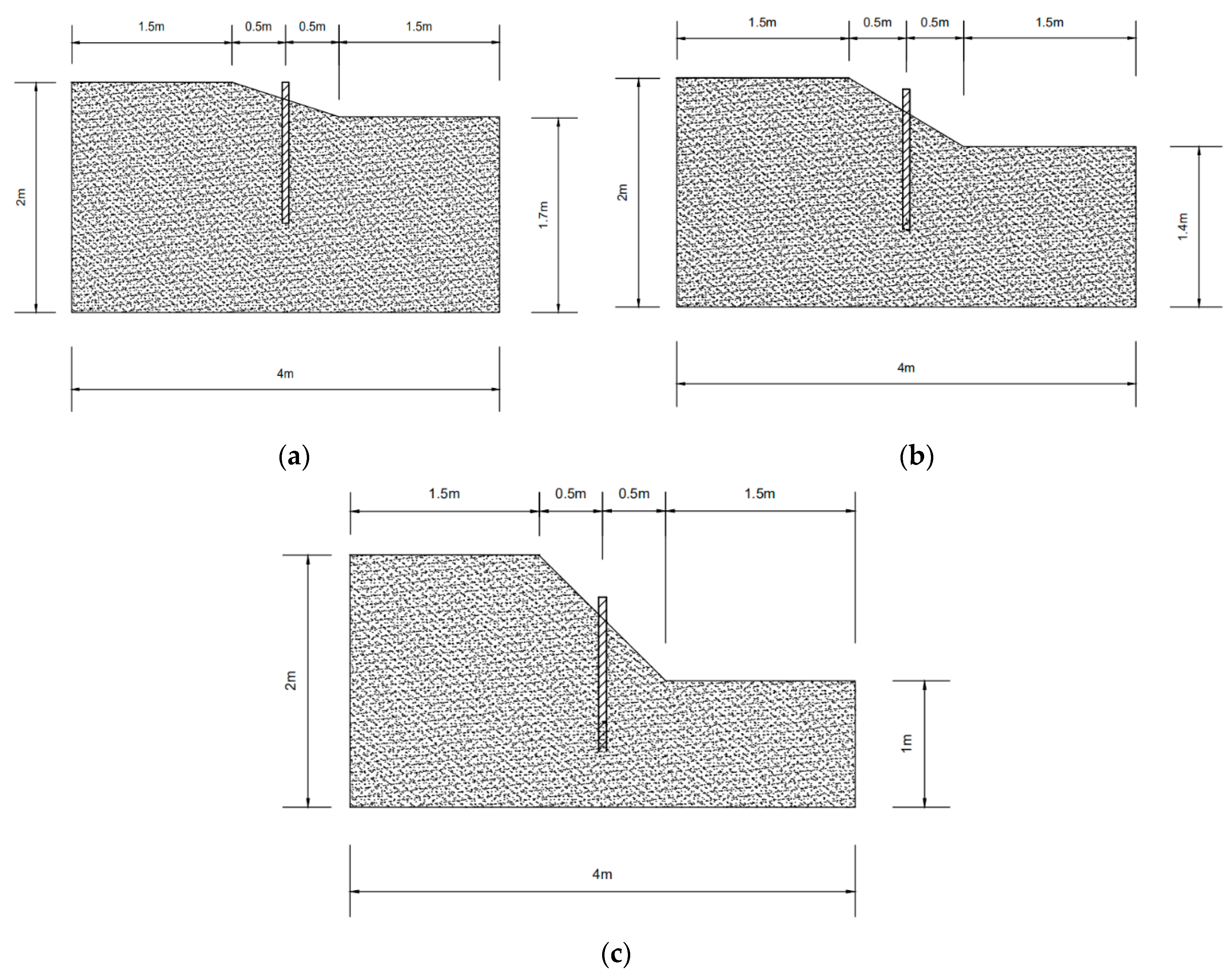
The FE analysis software ABAQUS was used to analyze pile foundation bearing characteristics under complex loads on different slopes [27]. Three numerical models with the tilt angle of 15 degrees, 30 degrees, and 45 degrees were established for the homogeneous soil slope, which had a simple polygonal section with a size of 4 m × 2 m × 2 m. The single pile was embedded in the middle of the slope under the diameter 5 cm and the length 1.2 m, with 15 cm extending past the soil surface. Figure 5 presents the sketch diagrams of the three models.
4.2. Model Establishment
The smaller the mesh size was, the higher the accuracy, but the amount of calculation was large [27]. According to the model size of the soil, the C3D8R element was selected to divide the soil model; the grid subdivision interval was 0.1 m, and a total of 16,034 elements were obtained. The Mohr–Coulomb model is widely used in geotechnical engineering, which can commendably simulate the mechanical deformation of the soil under shear failure [28]. The Mohr–Coulomb model was also chosen for this study. Table 1 provides the soil’s parameters and characteristics. The linear elastic constitutive model based on the generalized version of Hooke’s law was adopted to simulate the pile in the sloping ground, which mainly involved two parameters, the Poisson’s ratio (v) and elastic modulus (E). The researchers discovered that the two factors varied with the temperature and other field variables [27,28]. Table 2 presents the material parameters.
The C3D8R element was also selected to divide the pile model; the smaller the mesh size was, the higher the accuracy, but the amount of calculation was large. According to the model size of the pile, the grid subdivision interval was 0.02 m, and a total of 1920 elements were obtained. In order to simulate the interaction between pile and soil, the normal behavior was used; rigid contact was used in the properties of the pile side and pile end surface. Simultaneously, considering the friction between the pile side and the soil under the load, the friction formulation used a penalty, and the friction coefficient was set as 0.35 in the pile side’s tangential action. The boundary condition was set so that the displacement constraints in X and Y directions were applied around the model, all degrees of freedom were constrained at the bottom of the model, and the influence of the initial stress field of soil was considered.
5. 3D FEM Analysis
5.1. Analysis of Test Results and Finite Element Results
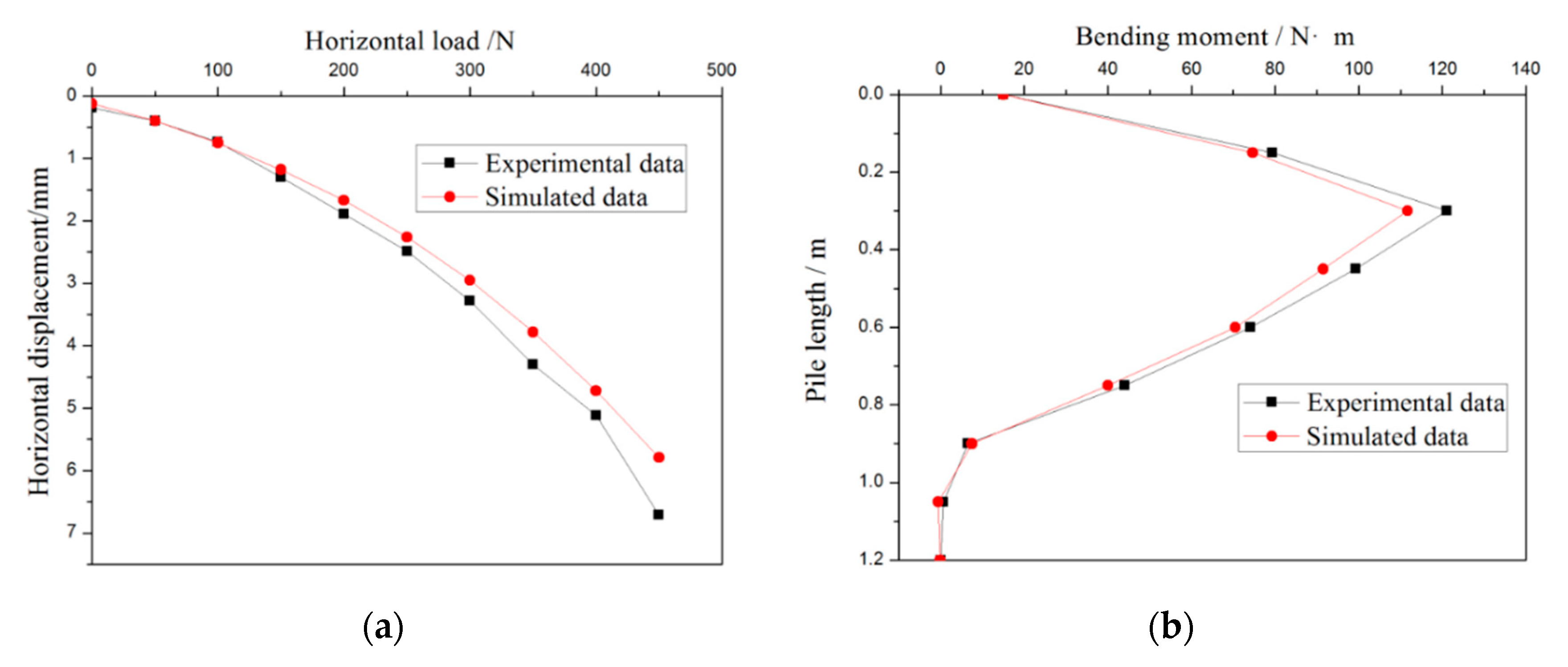
To confirm the correctness of the finite element parameter settings, a model consistent with the test was established for calculation. According to Figure 6, the results of the pile’s internal force and load–displacement were extracted and compared with the experimental results.
When the load was 450 N, the maximum displacement obtained by the simulation was 6.2 mm (see Figure 6a), the experimental result was 7 mm, and the error was 12.9%. The maximum bending moment of the pile by the experiment was 123 N·m (see Figure 6b), the maximum bending moment of the pile by the simulation was 111 N·m, and the error was 10.8%. The main reason for the error may have been that the soil used by the numerical simulation was isotropic, while the soil used by the experimental was not, and the error was not big. The curves of comparison of load–displacement on the pile between the test and the simulation had the same trend. The bending moment of the two results was almost the same. This showed that the parameter setting of the finite element calculation was more reasonable.
5.2. Distribution of the Earth Pressure
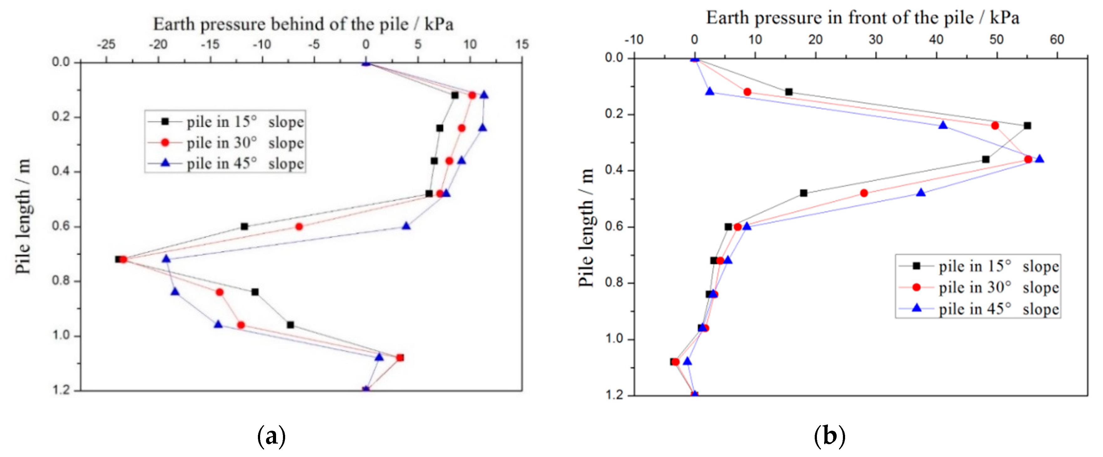
The earth pressure behind the pile was an essential factor influencing structure safety. To study the change of the soil pressure behind the pile under different slopes, the earth pressure’s distribution behind and before the piles with three slopes were computed. Figure 7 presents the calculation results.
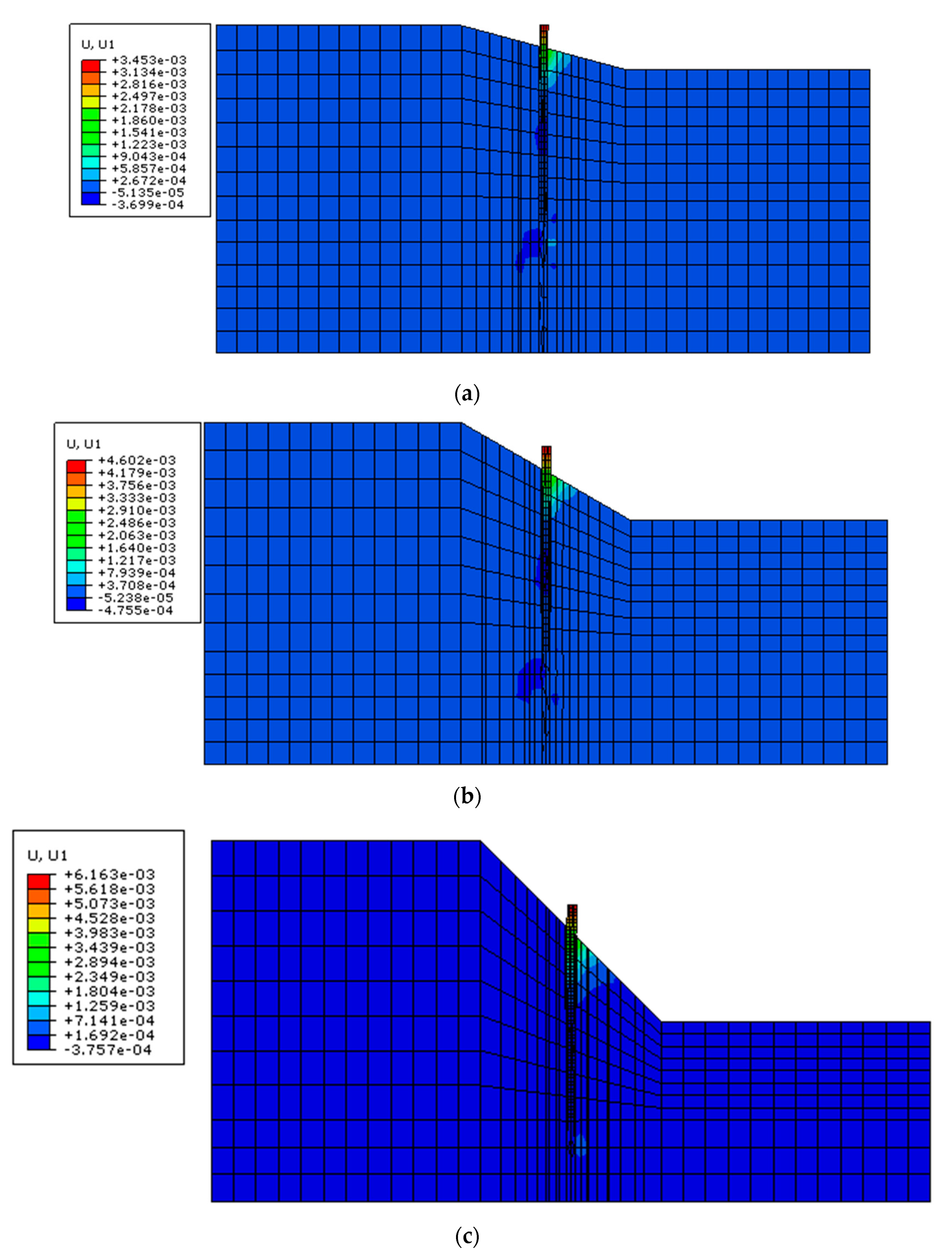
5.3. Displacement of Piles under Different Slopes
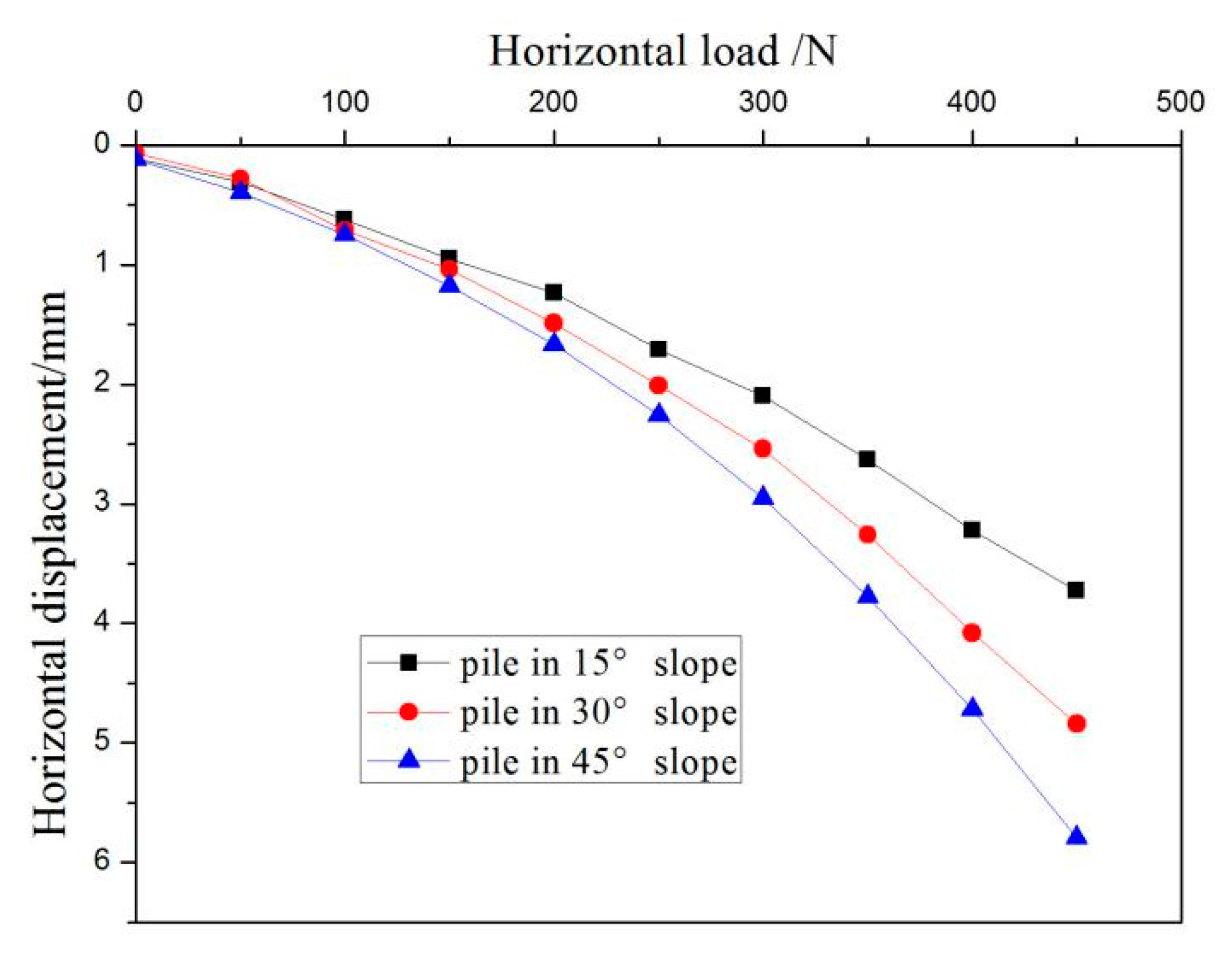
The displacement of the pile head was an important sign of slope failure. The piles’ different lateral load–displacement on a slope with inclination angles of 15°, 30°, and 45° were simulated and compared (see Figure 8). When the pile’s lateral load increased to 450 N, the horizontal displacements’ corresponding values of the single pile for angles of 15°, 30°, and 45° were 3.45 mm, 4.60 mm, and 6.16 mm, respectively. Figure 9 describes the displacement of pile–soil interaction.
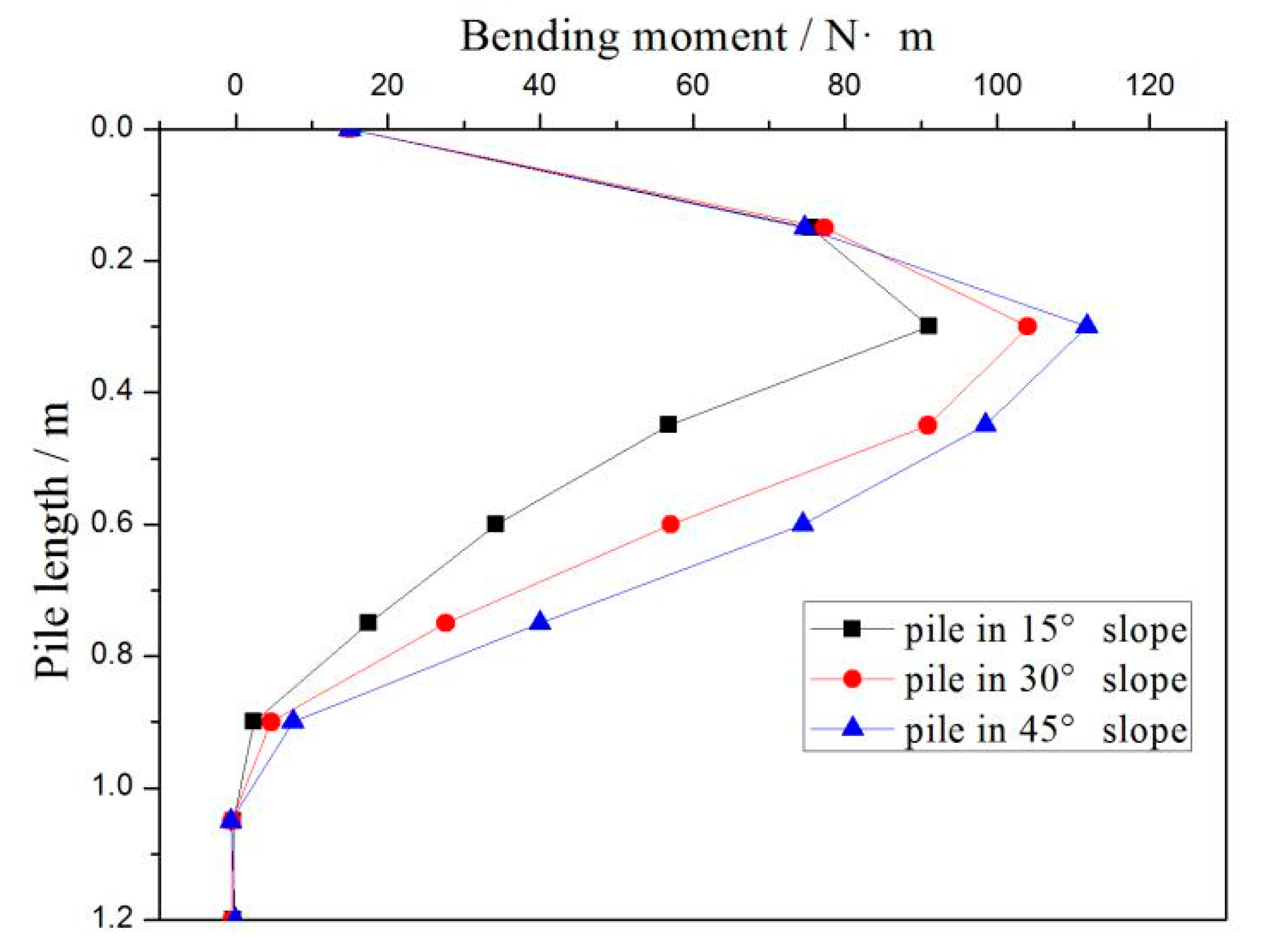
5.4. Bending Moment of Piles under Different Slopes
One of the crucial parameters of pile structure design is the bending moment. To discuss the variation law of pile bending moment under different slopes, the pile’s lateral load was 450 N, and the corresponding values of the slope angles were 15°, 30°, and 45°. The calculation result is shown in Figure 10.
6. Discussion
6.1. Variation of Soil Pressure around the Pile with Depth
Different slopes have different soil distributions around the pile, which leads to different soil pressures around the pile [29,30].
Due to the existence of the slope, the soil pressure before and behind the pile was distributed asymmetrically (see Figure 7). The changing trend was the same under different slopes. The soil pressure from 0 to 0.6 m depth behind the pile was the thrust (see Figure 7a), which from 0.6 to 1 m behind the pile was the resistance, and the earth pressure below 1 m gradually decreased to zero. The soil’s thrust behind the pile increased with the increment of the slope angle, while the pile resistance was decreasing. Tang [31] experimentally determined that when the lateral load was small, the soil pressure behind the anti-slide pile gradually decreased below the ground. This difference might affect the shape of the pile. However, the soil resistance before the pile increased first and then decreased from the pile head to section 1 m (see Figure 7b); the soil pressure in front of the pile under 1 m was gradually reduced to zero. With the increment of the slope angle, the maximum soil pressure occurred before the pile moved down along the pile. Because of the increment of soil asymmetry around the pile, the pile needed to transmit the load from the pile top to the deeper stable soil layer to balance the asymmetry of the pile head load and soil around the pile. In conclusion, with the increasing slope angle, the earth pressure behind and before the pile increased accordingly. The overall slope risk and soil pressure of the pile both increased.
6.2. Different Slope Gradients Affect the Internal Force and Displacement
The pile displacement under the various lateral load was affected by the slope, and similarly, the internal force distribution of the pile was affected by different slopes [32].
A gradually increased load caused an increment in the pile’s horizontal displacement, and the slope of 45° increased faster than the slope of 15° (see Figure 8). When lateral load acted on the pile top with a gentle slope, the contact at the pile–soil interface was very small. The slope then became larger, and the interface between the soil and the pile cracked noticeably (see Figure 9). At this time, the earth pressure on the pile side was less than that on the other side, so that a specific horizontal thrust was generated on the pile. As the slope angle increased, the pile horizontal thrust increased accordingly.
Under the lateral load, the bending moment gradually increased from the pile top downwards and reached the maximum at 0.3 m below the pile head. The depth at this time was six times the pile diameter (see Figure 10), and then it gradually decreased to zero. In the structural design of the round pile, it is recommended to strengthen the steel bar at a position several times the diameter of the pile below the pile top so as to increase the horizontal bearing capacity. Wang [33,34] theoretically calculated that the maximum bending moment of the anti-slide pile was about 2 m under the sliding surface (1 times the pile width). This difference might be caused by the shape of the pile and stiffness of the rock under the sliding surface. When the pile head was subjected to a lateral load of 450 N, the maximum bending moments of the piles were 91.05 N·m, 104 N·m, and 111.7 N·m, corresponding to 15°, 30°, and 45° slopes, respectively. The maximum bending moments of the piles increased with an increment of the slope gradient.
The pile material also affects the pile head displacement under the lateral load [35]. The material of the pile is generally reinforced concrete, and waste steel rails can also be used instead of steel bars. This material substitution can improve the shear resistance of the pile. The combined structural stresses of this approach need to be further studied. When the position of the pile and pile shape changes on the slope, the soil pressure around the pile will also change. The effect of the pile position change on the internal force of the pile and the pile top displacement needs further research.
7. Conclusions
The mechanical performance of a single pile under combined load is very significant in engineering design. This article used experimental and finite element numerical calculation methods to explain the slope angle’s influence on the single pile lateral response under combined loads. The variation law of earth pressure around the pile, pile head displacement change with load, and the change of the pile internal force were fully studied.
A self-made loading system was used to conduct the experiment. With the slope gradient increase, the horizontal thrust force acting on a pile generally increased; however, the single pile’s horizontal bearing capacity was gradually reduced. The soil’s thrust behind the pile increased with the slope angle increase, while the resistance of the pile decreased. Increased slope gradient and slope risk caused an increment of the bending moment and the horizontal displacement.
Author Contributions
Formulated the theme: J.Z.; conceptualization: J.Z., X.W., H.W., and H.Q.; outline of the review: H.W.; reviewed the literature: H.Q. and X.W.; software: H.W.; investigation: J.Z.; data: X.W.; drafted and revised the manuscript: J.Z.; revised the manuscript: H.W., J.Z., H.Q., and X.W.; reviewed, revised, and finalized the manuscript: H.W.; supervision: H.Q.; funding acquisition: J.Z. All authors have read and agreed to the published version of the manuscript.
Funding
Key Scientific and Technological Projects of Henan Province (Grant No. 192102310226) and the Training Program for Young Scholar in Colleges and Universities of Henan Province (Grant No. 2019GGJS041), China Postdoctoral Science Foundation (Grant No. 2020M672202) and Key projects of universities in Henan Province (Grant No. 20A570002), National Natural Science Foundation of China (Grant No. 51508163).
Acknowledgments
All authors thank the anonymous reviewers and the editor for the constructive comments on the earlier version of the manuscript.
Conflicts of Interest
The authors declare no conflict of interest.
References
- Ito, T.; Matsui, T.; Hong, W.P. Design method for stabilizing piles against landslide-one row of piles. Soils Found. 1981, 21, 21–37. [Google Scholar] [CrossRef] [Green Version]
- Poulos, H.G. Design of reinforcing piles to increase slope stability. Can. Geotech J. 1995, 32, 8–18. [Google Scholar] [CrossRef]
- Chow, Y.K. Analysis of piles used for slope stabilization. Int. J. Numer. Anal. Meth. Geomech. 1996, 20, 635–646. [Google Scholar] [CrossRef]
- Cai, F.; Ugai, K. Response of flexible piles under laterally linear movement of the sliding layer in landslides. Can. Geotech. J. 2003, 40, 46–53. [Google Scholar] [CrossRef]
- Ahmadi, S.F.; Eskandari, M. Vibration analysis of a rigid circular disk embedded in a transversely isotropic solid. J. Eng. Mech. 2014, 140, 04014048. [Google Scholar] [CrossRef]
- Ahmadi, S.F.; Eskandari, M. Axisymmetric circular indentation of a half-space reinforced by a buried elastic thin film. Math. Mech. Solids 2014, 19, 703–712. [Google Scholar] [CrossRef]
- Zhang, Z.Q.; Pan, E. Vertical vibration of a rigid circular disc embedded in a transversely isotropic and layered poroelastic half-space. Eng. Anal. Bound. Elem. 2020, 118, 84–95. [Google Scholar] [CrossRef]
- Dong, J.; Zhong, S.; Wang, H.L.; Wu, Z.H. Dynamic response characteristics of crossing tunnels under heavy-haul train loads. Geomech. Eng. 2020, 20, 103–112. [Google Scholar] [CrossRef]
- Liu, J.H.; Zhao, M.H.; Yang, M.H. Model tests on bridge pile foundation in high and steep rock slopes. Chin. J. Geotech. Eng. 2009, 31, 372–377. [Google Scholar]
- Broms, B.B. Lateral resistance of piles in cohesionless soils. J. Soil Mech. Found. Eng. Div. ASCE 1964, 90, 123–156. [Google Scholar]
- Randolph, M.F. The response of flexible piles to lateral loading. Geotechnique 1981, 31, 247–259. [Google Scholar] [CrossRef]
- Fan, C.C.; Long, J.H. Assessment of exiting methods for predicting soil response of laterally loaded piles in sand. Comput. Geotech. 2005, 32, 274–289. [Google Scholar] [CrossRef]
- Chik, Z.; Abbas, J.; Taha, M.; Shafiqu, Q.S.M. Lateral behavior of single pile in cohesionless soil subjected to both vertical and horizontal loads. Eur. J. Sci. Res. 2009, 29, 194–205. [Google Scholar]
- Comodromos, E.M.; Papadopoulou, M.C.; Laloui, L. Contribution to the design methodologies of piled raft foundations under combined loadings. Can. Geotech. J. 2016, 53, 559–577. [Google Scholar] [CrossRef]
- Begum, N.A.; Muthukkumaran, K. Experimental investigation on single model pile in sloping ground under lateral load. Int. J. Geotech. Eng. 2009, 3, 133–146. [Google Scholar] [CrossRef]
- Chien, C.J.; Lin, S.S.; Yang, C.C.; Liao, J.C. Lateral performance of drilled shafts due to combined lateral and axial loading. J. Mech. 2013, 29, 685–693. [Google Scholar] [CrossRef]
- Xie, J.M.; Xu, X.C.; Chen, S.X.; Jian, L.F. Experimental study on horizontal bearing deformation of slope pile foundation. Sci. Technol. Eng. 2013, 13, 5031–5036. [Google Scholar]
- Zhang, J.W.; Kong, M.; Ma, J.D. Study on bearing capacity of the single pile on slope under complex loads. Build. Struct. 2014, 8, 96–99. [Google Scholar]
- Kershaw, K.A.; Luna, R. Full-scale field testing of micropiles in stiff clay subjected to combined axial and lateral loads. J. Geotech. Geoenviron. Eng. 2014, 140, 255–261. [Google Scholar] [CrossRef]
- Zuo, D.J.; Chen, L.; Tian, Z.W.; Qi, C.G. Numerical study on mechanical characteristics of pile groups of wharf foundation under lateral and vertical cyclic loadings. Chin. J. Geotech. Eng. 2015, 37, 51–56. [Google Scholar]
- Muthukkumaran, K.; Begum, N.A. Experimental Investigation of Single Model Pile Subjected to Lateral Loading Sloping Ground. Geotech. Geol. Eng. 2015, 33, 935–946. [Google Scholar] [CrossRef]
- Jegatheeswaran, B.; Muthukkumaran, K. Behavior of pile due to combined loading with lateral soil movement. Int. J. Geo Eng. 2016, 7, 8. [Google Scholar] [CrossRef]
- Matlock, H. Correlations for design of laterally loaded piles in soft clay. In Proceedings of the 2nd Offshore Technology Conference, Houston, TX, USA, 22–24 April 1970; British Maritime Technology: Teddington, UK, 1970; Volume 1, pp. 577–594. [Google Scholar]
- Rao, S.N.; Ramakrishna, V.T.; Balarama, G. Behavior of pile supported dolphins in marine clay under lateral loading. J. Geotech. Eng. 1996, 122, 607–612. [Google Scholar] [CrossRef]
- Rao, S.N.; Ramakrishna, V.T.; Babu, M. Influence of rigidity on laterally loaded pile groups in marine clay. J. Geotech. Geoenviron. Eng. 1998, 124, 542–549. [Google Scholar] [CrossRef]
- Wang, H.; Lv, Z.; Zhang, J.; Yue, J.; Qin, H.; Hung, C. Internal Force Analysis of Buried-boring Piles in the Yuanzishan Landslide. Appl. Sci. 2020, 10, 5416. [Google Scholar] [CrossRef]
- Kim, Y.H.; Jeong, S.S. Analysis of soil resistance on laterally loaded piles based on 3D soil-pile interaction. Comput. Geotech. 2011, 38, 248–257. [Google Scholar] [CrossRef]
- Xu, L.Y.; Pan, J.M.; Xue, Y.Y.; Cai, F.F. A Numerical Investigation of Influence of Low-Plasticity Fines in Sand on Lateral Response of Piles. Mar. Geores. Geotech. 2019, 38, 302–311. [Google Scholar] [CrossRef]
- Guo, W.; Qin, H. Thrust and bending moment of rigid piles subjected to moving soil. Can. Geotech. J. 2010, 47, 180–196. [Google Scholar] [CrossRef] [Green Version]
- Standardization Administration of China. JGJ 94-2008: Technical Code for Building Pile Foundations; Standardization Administration of China: Beijing, China, 2008. (In Chinese) [Google Scholar]
- Tang, H.; Hu, X.; Xu, C.; Li, C.; Yong, R.; Wang, L. A novel approach for determining landslide pushing force based on landslide-pile interactions. Eng. Geol. 2014, 182, 15–24. [Google Scholar] [CrossRef]
- Qin, H.; Guo, W. Response of piles subjected to progressive soil movement. Geotech. Test. J. 2016, 39, 106–125. [Google Scholar] [CrossRef] [Green Version]
- Wang, H.; Wang, P.; Qin, H.Y. Method to Control the Deformation of Anti-Slide Piles in Zhenzilin Landslide. Appl. Sci. 2020, 10, 2831. [Google Scholar] [CrossRef] [Green Version]
- Wang, H.; Lv, Z.Y.; Qin, H.Y. Deformation Control Method of the Antislide Pile under Trapezoidal Load in the Zhangjiawan Landslide. Adv. Civil Eng. 2020, 2020, 1405610. [Google Scholar] [CrossRef]
- Stacul, S.; Squeglia, N.; Morelli, F. Laterally Loaded Single Pile Response Considering the Influence of Suction and Non-Linear Behaviour of Reinforced Concrete Sections. Appl. Sci. 2017, 7, 1310. [Google Scholar] [CrossRef] [Green Version]
Figure 1.
Strain monitoring of piles: (a) location of strain gauges; (b) multi-point static strain gauges (model:CM2B).
Figure 1.
Strain monitoring of piles: (a) location of strain gauges; (b) multi-point static strain gauges (model:CM2B).

Figure 2.
Test of piles on slope: (a) test device design; (b) installation of test monitoring equipment.
Figure 2.
Test of piles on slope: (a) test device design; (b) installation of test monitoring equipment.

Figure 3.
The curve of the pile’s load–displacement under lateral load.

Figure 4.
Pile bending moment under different loads.

Figure 5.
Sketch diagram of model with different slope angle (in meters): (a) 15° slope angle; (b) 30° slope angle; (c) 45° slope angle.
Figure 5.
Sketch diagram of model with different slope angle (in meters): (a) 15° slope angle; (b) 30° slope angle; (c) 45° slope angle.

Figure 6.
Comparison of test results and our finite element calculated values of the pile under various load: (a) load–displacement; (b) bending moment.
Figure 6.
Comparison of test results and our finite element calculated values of the pile under various load: (a) load–displacement; (b) bending moment.

Figure 7.
Soil pressure around piles under different slopes: (a) soil pressure behind the pile; (b) soil pressure in front of the pile.
Figure 7.
Soil pressure around piles under different slopes: (a) soil pressure behind the pile; (b) soil pressure in front of the pile.

Figure 8.
Curves of comparison of the load–displacement on slope piles with different angles.

Figure 9.
The displacement of pile–soil interaction under the lateral load of 450 N (unit: m): (a) horizontal displacement of 15° slope angle; (b) horizontal displacement of 30° slope angle; (c) horizontal displacement of 45° slope angle.
Figure 9.
The displacement of pile–soil interaction under the lateral load of 450 N (unit: m): (a) horizontal displacement of 15° slope angle; (b) horizontal displacement of 30° slope angle; (c) horizontal displacement of 45° slope angle.

Figure 10.
The bending moments of piles with different slope angles.


Table 1.
Experimental parameters of geotechnical materials.
| Density/ ρ(g/cm3) | Cohesion/c(kPa) | Modulus/Es(MPa) | Moisture Content/w(%) | Internal Friction Angle/φ(°) |
|---|---|---|---|---|
| 1.95 | 4.3 | 12.5 | 5.4 | 32 |
Table 2.
The model pile’s calculation parameters.
| Elastic Modulus/(GPa) | Poisson’s Ratio/v | Pile Diameter/d(m) | Density/ρ(g/cm3) | Pile Length/L(m) |
|---|---|---|---|---|
| 20 | 0.12 | 0.05 | 2.40 | 1.2 |
© 2020 by the authors. Licensee MDPI, Basel, Switzerland. This article is an open access article distributed under the terms and conditions of the Creative Commons Attribution (CC BY) license (http://creativecommons.org/licenses/by/4.0/).
Share and Cite
MDPI and ACS Style
Zhang, J.; Wang, X.; Wang, H.; Qin, H. Model Test and Numerical Simulation of Single Pile Response under Combined Loading in Slope. Appl. Sci. 2020, 10, 6140. https://0-doi-org.brum.beds.ac.uk/10.3390/app10176140
AMA Style
Zhang J, Wang X, Wang H, Qin H. Model Test and Numerical Simulation of Single Pile Response under Combined Loading in Slope. Applied Sciences. 2020; 10(17):6140. https://0-doi-org.brum.beds.ac.uk/10.3390/app10176140
Chicago/Turabian StyleZhang, Jianwei, Xiaoju Wang, Hao Wang, and Hongyu Qin. 2020. "Model Test and Numerical Simulation of Single Pile Response under Combined Loading in Slope" Applied Sciences 10, no. 17: 6140. https://0-doi-org.brum.beds.ac.uk/10.3390/app10176140
Note that from the first issue of 2016, this journal uses article numbers instead of page numbers. See further details here.