Computer-Aided Design and Kinematic Simulation of Huygens’s Pendulum Clock


1
Department of Engineering Graphics, University of Seville, 41092 Seville, Spain
2
Department of Engineering Graphics, Design, and Projects, University of Jaen, 23071 Jaen, Spain
3
University of Seville, 41092 Seville, Spain
*
Author to whom correspondence should be addressed.
Appl. Sci. 2020, 10(2), 538; https://0-doi-org.brum.beds.ac.uk/10.3390/app10020538
Submission received: 25 November 2019
/
Revised: 29 December 2019
/
Accepted: 9 January 2020
/
Published: 10 January 2020
(This article belongs to the Special Issue Applied Sciences to the Study of Technical Historical Heritage and/or Industrial Heritage)
Abstract
:This article presents both the three-dimensional modelling of the isochronous pendulum clock and the simulation of its movement, as designed by the Dutch physicist, mathematician, and astronomer Christiaan Huygens, and published in 1673. This invention was chosen for this research not only due to the major technological advance that it represented as the first reliable meter of time, but also for its historical interest, since this timepiece embodied the theory of pendular movement enunciated by Huygens, which remains in force today. This 3D modelling is based on the information provided in the only plan of assembly found as an illustration in the book Horologium Oscillatorium, whereby each of its pieces has been sized and modelled, its final assembly has been carried out, and its operation has been correctly verified by means of CATIA V5 software. Likewise, the kinematic simulation of the pendulum has been carried out, following the approximation of the string by a simple chain of seven links as a composite pendulum. The results have demonstrated the exactitude of the clock.
1. Introduction
The topic of this article is the subject of numerous publications [1,2,3], which demonstrates the interest therein and follows the line of research on the recovery of technical historical heritage [4,5,6,7,8,9], in particular that of antique clocks [10]. The sun and water were, in ancient times, the first references to the measurement of time. After these types of clocks, perfected by Egyptians and Greeks, hourglasses appeared, and subsequently, clocks with cog mechanisms were invented in the 13th century. In the 15th century, the first spring-powered timepieces were developed in Germany [11,12].
In the 16th century, major geographical discoveries provoked an interest in the precise determination of longitude at sea. Therefore, the lunar clock was invented, as were astronomic clocks [13,14]. By the 17th century, the cog-regulating pendulum of Christiaan Huygens had appeared, as had the discoveries of Robert Hooke with respect to the law of elasticity; these mechanical improvements contributed towards the invention of the first balance-spring-regulated pocket chronometer from Hooke and Huygens, which constituted a milestone in precision horology.
In the 18th century, John Harrison solved the problem of longitude, and certain elements were perfected, such as the profile of the teeth of the cogs and the compensation of the pendulum; these aspects contributed towards improving accuracy. Finally, in the 19th century, with the industrial revolution, mass production and mechanization appeared. These improvements in manufacturing technologies constituted major contributions towards the improvement of the precision of watchmaking mechanisms.
Christiaan Huygens (The Hague, Netherlands, 1629–1695) was one of the central characters of the scientific revolution in the 17th century alongside Francis Bacon, René Descartes, Galileo Galilei, and Isaac Newton. With training in physics, mathematics, and astronomy, he contributed notably by perfecting Kepler’s telescope, thereby discovering Titan and the Orion Nebula. In 1656, he invented the pendulum clock, after adding a pendulum to a clock driven by weights, so that the clock would keep the pendulum moving and regulate its progress [15]. After this discovery, he stated the pendulum theory employed to measure the acceleration of gravity and its variations with altitude and latitude [16,17,18].
He subsequently developed, with little success, a portable chronometer to make it easier for seafarers to determine geographical longitude at sea, based on the double suspension of the pendulum between cycloidal blades. Interest in his theories is still shown in various studies [19,20].
Huygens published several books, among which Horologium [21,22] stands out, in which he defines the first pendulum clock, and Horologium Oscillatorium [23,24,25], his masterpiece, where he describes the isochronous pendulum clock and studies the properties of the cycloid and of geometric curves in general.
Huygens’s pendulum clock is a notable example of technical historical heritage, although there are many projects for the recovery of cultural heritage in general. A good sample of these include the mechanical lion of Leonardo Da Vinci [26], the initiative of the Canarian Orotava Foundation of History of Science to study the machines invented by the distinguished Spanish engineer Agustín de Betancourt [27], the virtual reconstruction of the device by Juanelo Turriano to raise water from the Tagus river to the city of Toledo, Spain [28], the clock of the Cathedral of Santiago de Compostela, Spain [29], the Church of Santa María de Melque in Toledo, Spain [30], and the Church of San Agustín de la Laguna in Tenerife, Spain [31].
The objective pursued in this historical investigation consists of obtaining a reliable three-dimensional model and the simulation of its movement through the parametric software CATIA V5 [32] of the isochronous pendulum clock, as designed by Christiaan Huygens and published in 1673, to verify its correct operation and underline its exactitude. Its selection is due to the significant technological advance that it represented as the first reliable time meter, especially thanks to the use of the properties of the cycloid, and also for its historical interest, since the whole theory of pendulum movement that Huygens enunciated remains in force.
The contribution of this research lies in the fact that there is currently no 3D CAD model of this historical invention with any degree of detail, which would help in the comprehension of its general operation, which is anything but simple. This operation has been verified through simulations from its virtual recreation, generating videos to check the properties of the cycloid (isochronous movement), and therefore, the accuracy of its functioning.
Another objective of this 3D model is educational, as it is designed for display in a History of Technology museum or interpretation centre. The impact of this research depends on the future uses of the model, which include:
- Development of applications of virtual reality and augmented reality to promote the interaction of the user with the model which will help users to better understand its operation and to appreciate its classification for each element or system.
- Incorporation of the WebGL model into a website.
- 3D printing using additive manufacturing together with an animation created by a photorealistic organizer for its exhibition in a Museum, Interpretation Centre or Foundation.
2. The Isochronous Pendulum Clock
As previously stated, in 1673, Huygens published his masterpiece Horologium Oscillatorium, which was divided into five parts, wherein he describes the isochronous pendulum clock and studies the properties of the cycloid and geometric curves in general. He also indicated a certain length of the pendulum to produce a certain number of movements, and observed that the pendulum that marked seconds should measure approximately 99.42 cm.
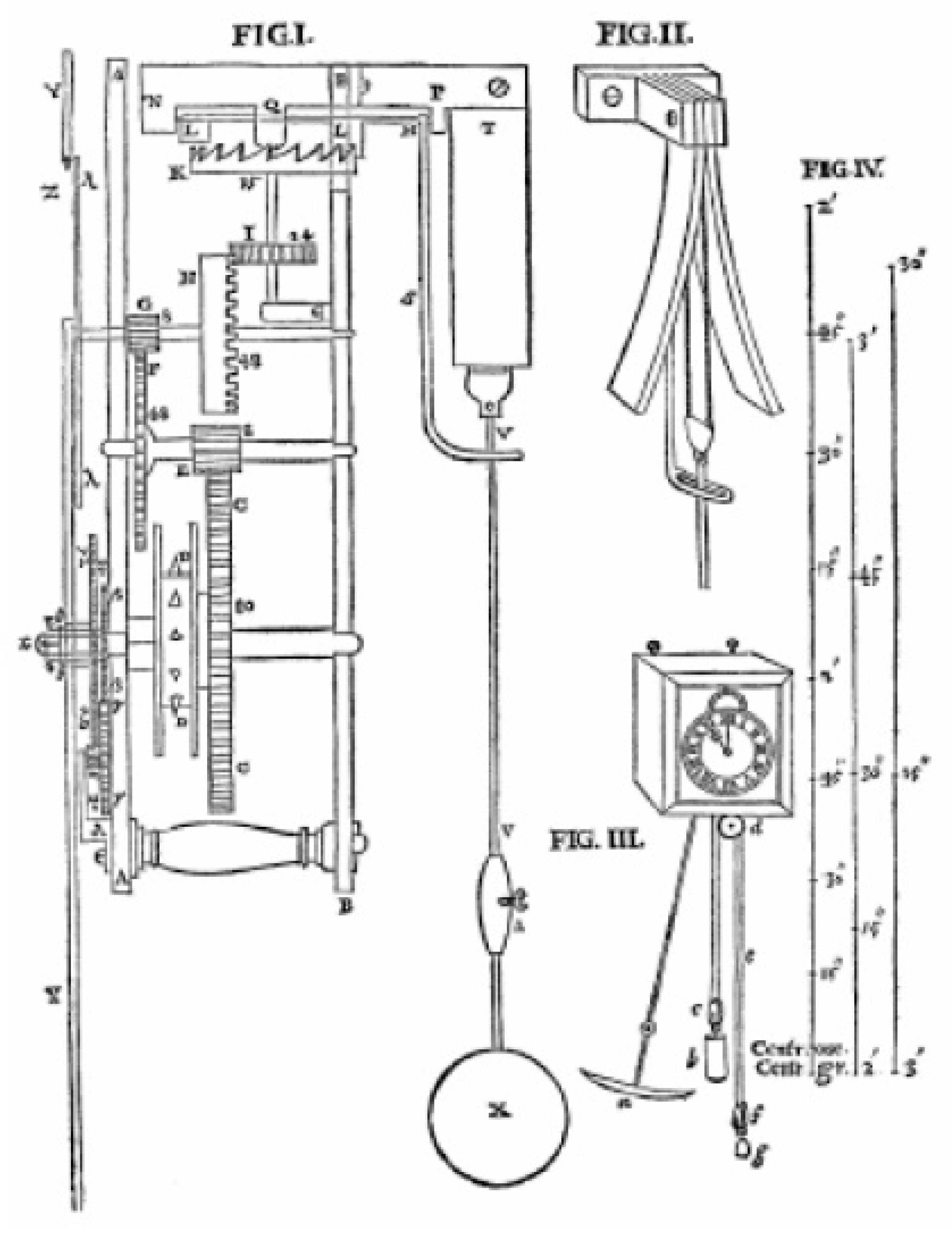
This research has been carried out based on the first three parts of the book. The first describes the clock (Figure 1) as consisting of three main subsets: The gear train, the mechanism of transformation of the circular movement into an oscillatory movement, and the elements associated with the movement of the pendulum.
The gear train is configured on three axes interconnected by wheel-pinion assemblies that are responsible for managing the clock hands. The mechanism of the transformation of the circular movement into an oscillatory movement is composed of a crown wheel, K, that rotates around the vertical axle and transforms its rotation into oscillation of the rod, S, thanks to a horizontal axle with vanes, LM, held by the so-called ‘Gnomons’ (parts where the axles are housed). Finally, the elements associated with the pendulum are the pendulum itself, its support, and the cycloidal blades that limit its movement on either side, transmitted thanks to the rod, S.
In the second and third parts of the work, the theoretical foundations are enunciated and demonstrated to achieve the isochrony of the pendulum, by forcing the pendulum to move tangent to two cycloidal blades, which describe its extremes, the cycloid, and, therefore, a tautochronous trajectory (isochronous movement). In this way, the pendulum achieves a constant period (one second) independent of the amplitude of the movement.
The understanding of the operation of the mechanism was not easy, although the main challenges faced in this research include the creation of the designs of the gears of different tooth profiles, the design of the two cycloidal blades (two coupled escapement-driven blades), the simulation of the pendulum movement, and especially, the behaviour of the strings that support the bob of the pendulum.
3. Sizing, Design, and Assembly of the Elements of the Isochronous Pendulum Clock
The clock design has been carried out independently for each of the three component parts: The gear train; the pendulum with the cycloidal blades; and the clamp (Gnomon P), the dimensions of which are explained in detail in the Horologium Oscillatorium. For this modelling phase, the Sketcher and Part Design modules of CATIA V5 were applied. These 3D CAD modelling techniques provide a fundamental tool in the process of designing of technical historical heritage, for example, in aerospace heritage [33], as a previous stage of CAE (computer-aided engineering) analysis [34,35] and, in general, as an application for any example of cultural heritage [36].
The only information available regarding the operation of the pendulum clock appears as a brief description of the component parts: The number of teeth of each wheel, the speed that each axle must have, and the dimensions that the pendulum must have in order to mark seconds. However, there is no information available regarding the shape and dimension of each piece, and hence the design proposed in this research has been made only with the graphic information available in Figure 1.
It is well-known that pendulum clocks are characterized by using an oscillating weight to measure time accurately, and that they enjoy the advantage that the pendulum behaves like a harmonic oscillator, that is, its oscillation cycles are produced in equal time intervals (periods), and only depend on its length (isochrony). For this reason, these pendulum clocks must remain in a fixed position, since any displacement would affect the movement of the pendulum and the accuracy of its operation. Therefore, the sizing of a pendulum clock is completely parametric, and depends only on the length of the pendulum, which uniquely implies a gear ratio.
The pendulum clock can therefore be considered as being divided into two distinct parts: on the one hand, there is gear train and, on the other hand, the pendulum which is made up of the cycloidal blades and the clamp (Gnomon P), the sizing of which is explained in detail in the book.
3.1. Gear Train
The gear train design is undoubtedly the first step in the redesign phase of the clock: It is decisive in the size of the resulting clock, since the distance between the axles is directly related to their primitive diameter. The gear train can be differentiated from the rest of the gears because the speed ratio of each pair of gears that are geared is directly related to the ratio of the diameters of the wheels, and this, in turn, is related to the ratio of the number of teeth. Therefore, the different speeds of rotation of each axle will be the speeds of the hands of the clock, which depends on the relation of the number of teeth and not of the size.
To obtain the speed ratios between gears, it suffices to use wheels whose number of teeth are in an inverse relationship, and the size of these gears will be determined by their own modulus (the gearing wheels have the same modulus).
Given the absence of detailed information regarding the dimensions of the elements, it has been assumed that the gear train as a whole would measure vertically one third or, at most, half the length of the pendulum. This assumption has enabled us to estimate that the primitive diameter, d, of the largest wheel (C—crown wheel), which has 80 teeth, is 240 mm, for which the modulus, m (the quotient between the primitive diameter and the number of teeth), is 3. It is known that the modulus is a standardized parameter, since it is decisive in the construction and calculation of gears, in such a way that all the data of the gearwheels is expressed as a function of said parameter. Thus, the complete pendulum clock design is based on this unit of measure.
Once all the gearing wheels were defined, the distance between the axles could be determined as the semi-sum of the primitive diameters of said wheels. Additionally, the decision was taken that the gear pressure angle should be the same, with the objective of transmitting movements and not forces and, on the other hand, considering that the distance between the AA and BB plates that form the structure of the clock (Figure 1) is 150 mm and the dimensions are 200 mm wide by 552 mm high.
Since the transmission between the gears must be carried out continuously to allow uniform movements, any of several curves could be chosen for the design of the tooth profile: The cycloid, the epicycloid, the hypocycloid, and the involute of the circle [37]. Finally, the profile of the involute of the circle was chosen because it can be traced with arcs of circumference, thereby obviating the freehand trace, and with it the error introduced [38].
To this end, our method of choice was that of Grant’s odontograph [39], which results in a curve that is a very good approximation to the theoretical profile. The design parameters of wheels and sprockets were chosen while taking into account both the requirements of the chosen tracing method and the basic conditions of the wheels and sprockets that engage [39,40].
Likewise, the 3D modelling of all teeth followed a common pattern of operation: First, a sketch was made, in which the tooth profile was drawn; secondly, an extrusion (pad) of that sketch was performed, to subsequently produce a circular matrix (circular pattern) of the extrusion; finally, a hole was made to accommodate the corresponding axle.
Once all the gears were defined, the positions of each of the five axles of the mechanism were determined by means of the semi-sum of the primitive diameters of each gear. This design was completely satisfactory, since it was verified that there were interferences between the gears by sliding the teeth between them, and allowing the precise operation of the clock.
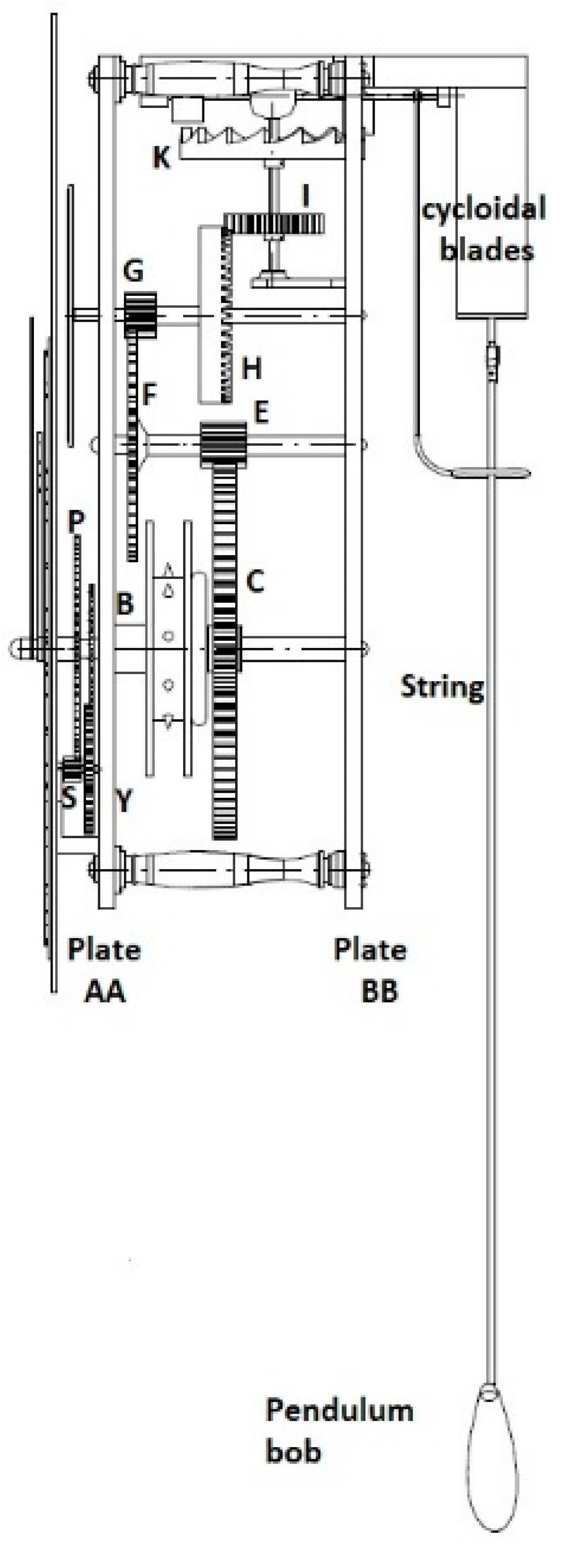
Due to the complexity of the final model (consisting of 49 different components), and to the fact that presenting the assembly plan would be extremely extensive, as would the detailed drawings of each dimensioned piece and the exploded view of the assembly to show its order of assembly in the search for the reproducibility of the work, we opted to include Figure 2, which shows only the front view of the 3D CAD model and indicates the nine wheels (I, H, G, F, E, C, B, Y, and P) and the pinion, S, as well as other main parts of the assembly. Likewise, Table 1 shows the main dimensional values determined in this study for all nine wheels and the pinion.
3.2. Cycloidal Blades
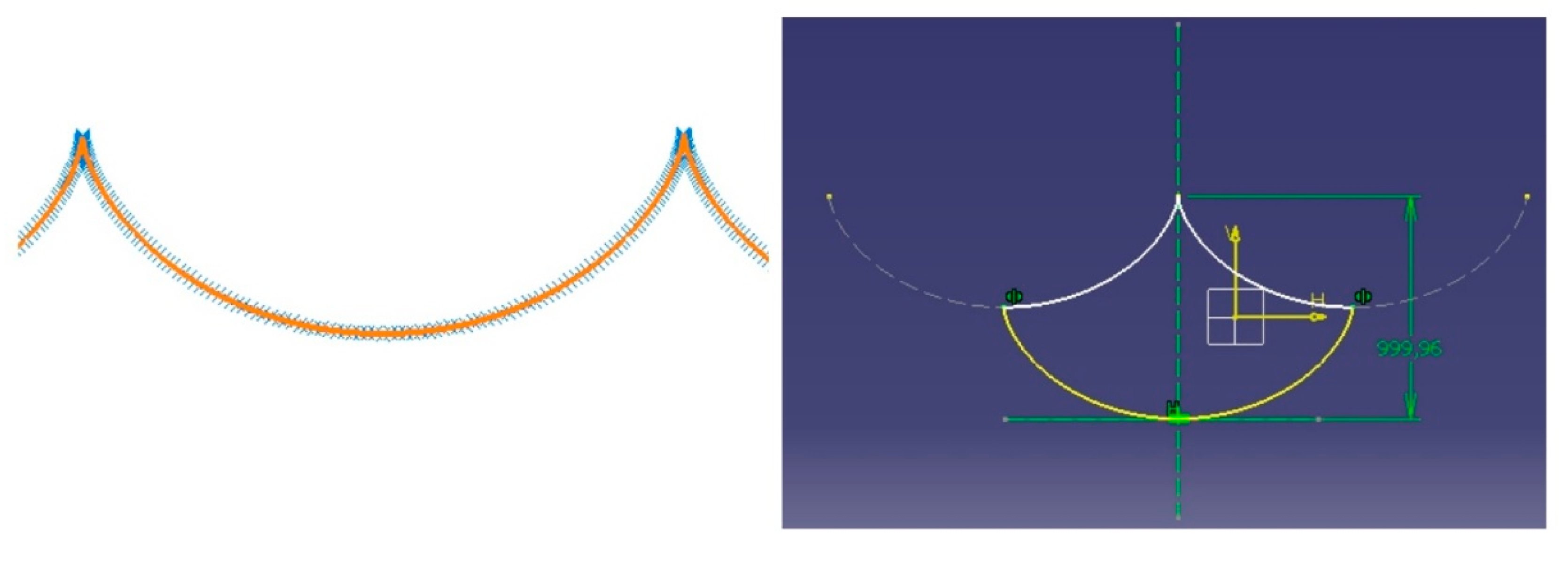
These elements constitute the key to the success of this pendulum clock. The cycloid is traced by faithfully following the method explained by Christiaan Huygens in his book Horologium Oscillatorium, where it is defined as the cyclic curve that is generated by a point when rolling (without sliding) a circle along a line (Figure 3).
This curve can be obtained in the DMU Kinematics Simulator module of CATIA V5, in which the software is instructed to draw the trajectory of a previously defined point of the circle, whereby this cycloidal curve describes a succession of points joined by a spline (Figure 4).
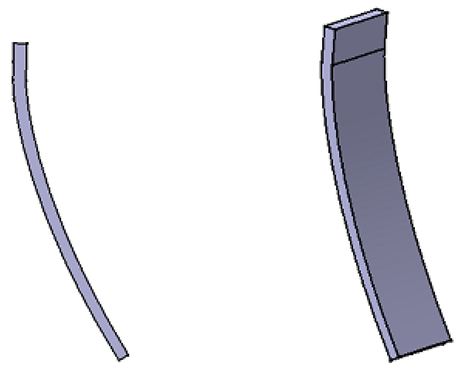
Once the cycloidal curve is obtained, and by extrusion of a closed sketch that is created from the cycloid, the 3D models of the two cycloid blades can be obtained (Figure 5).
3.3. Assembly of Subsets and Final Set
This operation was carried out in the CATIA V5 Assembly Design module through the application of a series of geometric and movement restrictions (degrees of freedom) to the different parts, which place them in their final positions. Thus, once each of the subsets was assembled, the final set could be assembled.
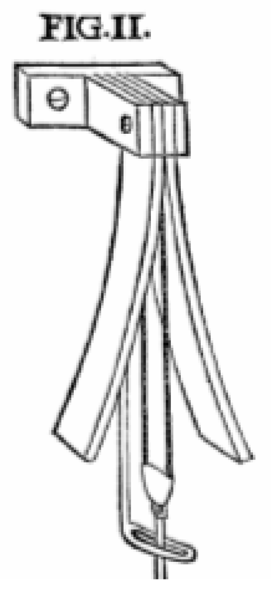
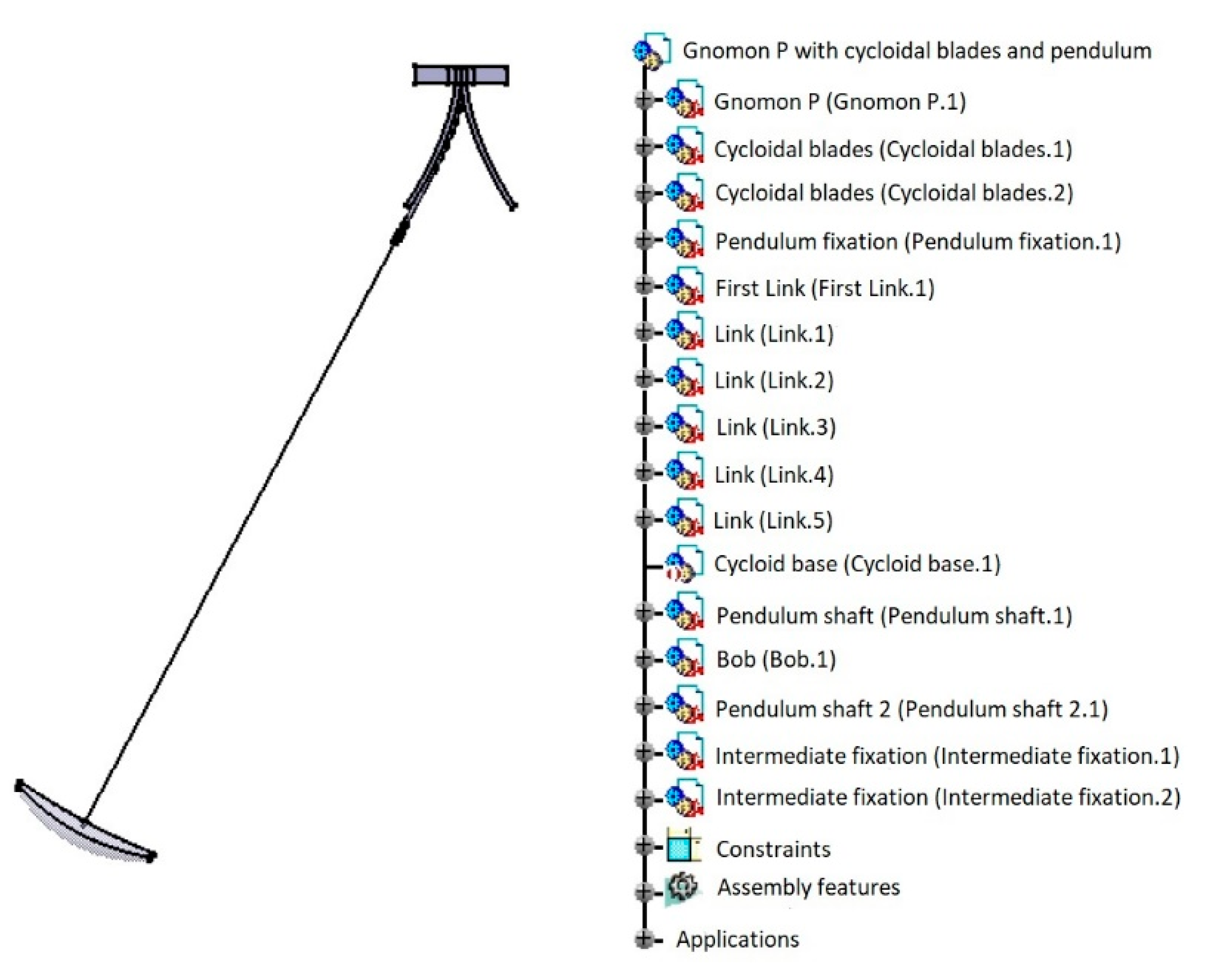
Among all the subsets, the pendulum is perhaps the most complicated. Since the pendulum is suspended by two strings between the cycloidal blades (Figure 6), and since CATIA V5 cannot model flexible elements such as the string, this difficulty was resolved by assimilating it into a chain formed by seven links, which represents an acceptable approximation of the real behaviour of the string. Figure 7 shows the pendulum geometry tree, where the various parts of this subset can be observed.
CATIA V5 considers each sub-assembly in a rigid way; if it becomes flexible and becomes an independent mechanism, then the possibility of relating it to another mechanism is lost, which is inconvenient for kinematic simulation.
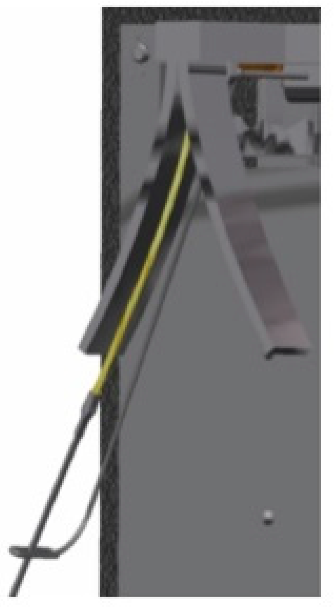
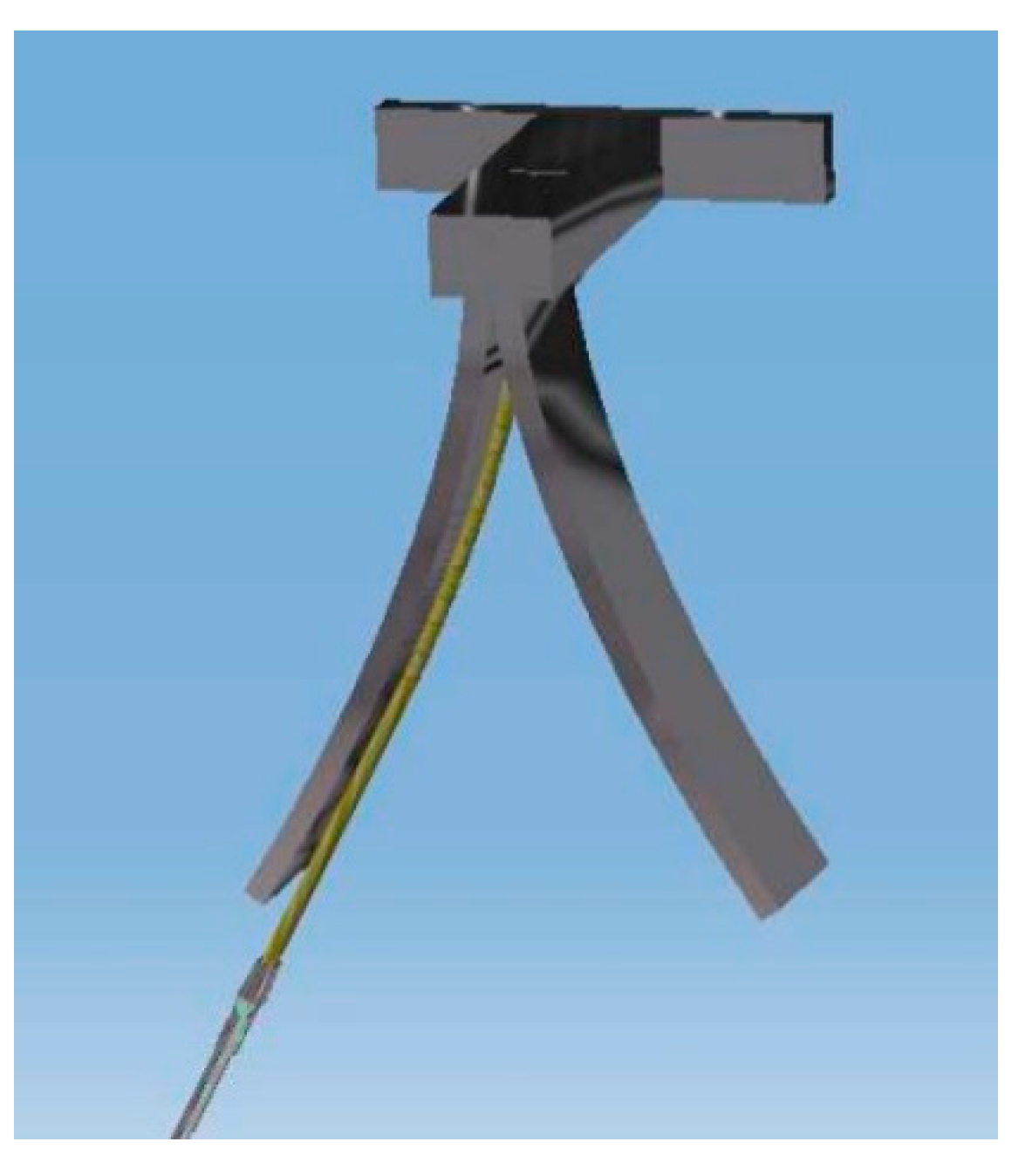
Likewise, the model of the chain (simulated string) was given a real look (Figure 8), in order to attain a satisfactory result.
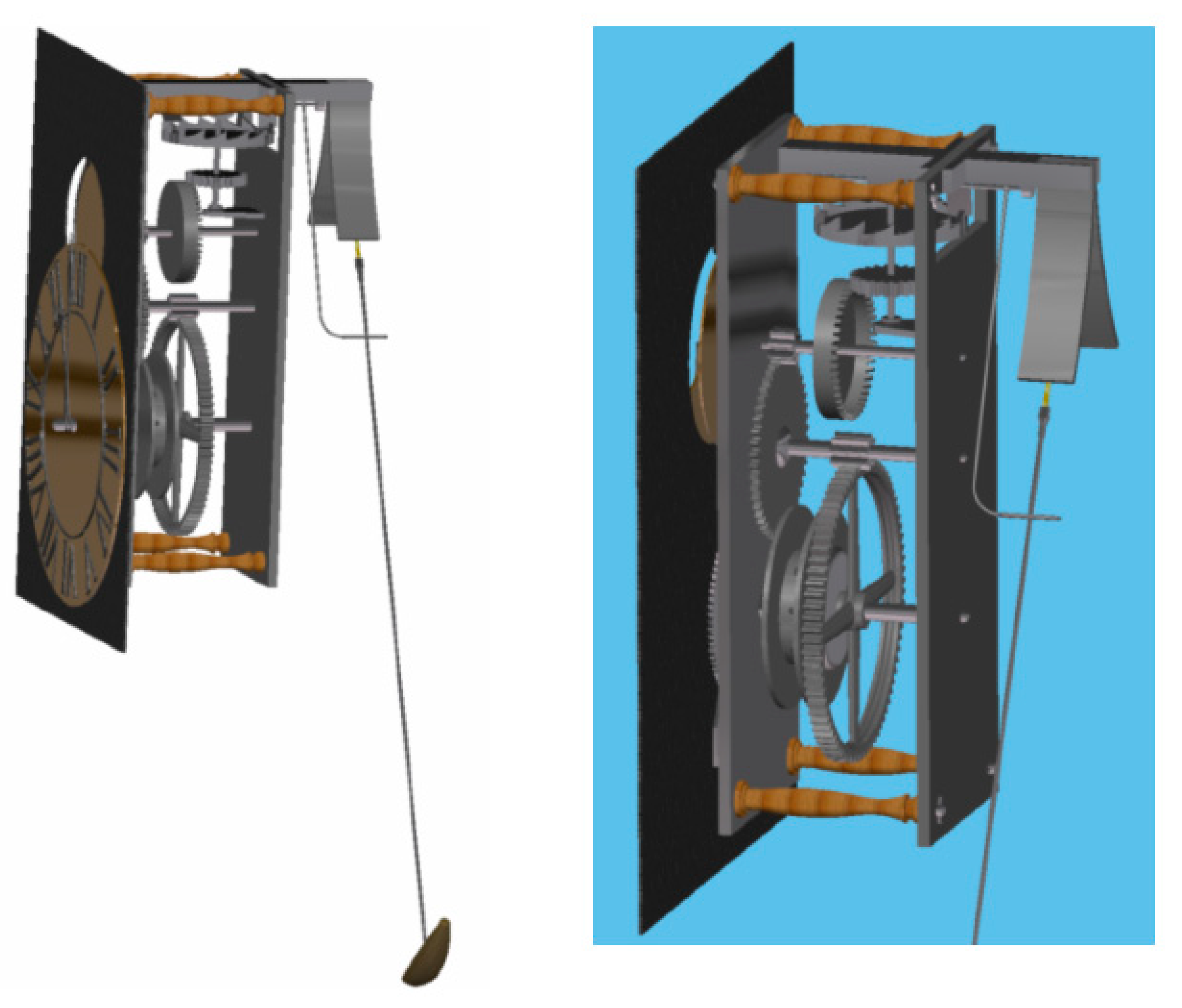
Finally, before obtaining the complete assembly of the isochronous pendulum clock (Figure 9), various sub-assemblies were made, such as that of the spheres, the second disk, and the pendulum.
4. Simulation of Pendulum Kinematics
For the kinematic simulation of the pendulum (the movement of which posed the most problematic phase), the DMU Kinematics Simulator module of CATIA V5 was applied. This module requires the existence of a fixed part for the simulation of a mechanism, and it was established at the beginning as a restriction, and subsequently the unions between the different parts were defined. Without doubt, the simulation of the movement of the pendulum presented the greatest difficulty.
This simulation raised two main drawbacks. In the first place, CATIA V5 fails to allow flexible elements, such as the string, to be modelled, which has been solved by approaching the string as a chain of seven links. Secondly, the possibility that the chain adapts to the cycloidal blades in its periodic movement should also be borne in mind. CATIA has the capability for contact detection, but if this option is activated, then at the moment it detects a contact, the simulation would halt.
The movement of the pendulum was resolved in two ways: By means of commands, that is, by conveniently moving each degree of freedom; and by means of functions, that is, by imposing a function on each degree of freedom of the driving mechanism. Therefore, since the string was modelled as a seven-link chain, at each point of connection between the links there is a degree of freedom of rotation, which are the drivers of the pendulum movement.
By means of command simulation (Figure 10), one of the properties of the cycloid discovered by Huygens is verified: “The evolute of a cycloid is the displaced cycloid itself”, since it can be observed that the cycloid of the wooden base and the cycloid of the cycloidal blades are the same but displaced.
To this end, the simulation of a single movement period is edited with commands. One by one the degrees of freedom are moving, in the most similar way to reality, in the ‘Kinematic Simulation’ window. At the same time, in the ‘Edit Simulation’ window, frames are successively inserted for each movement of a degree of freedom made.
Subsequently, the commands were gradually moved, so that when they reach the cycloidal blades, the links adapted to them as much as possible, thereby ensuring, as far as possible, the tangency of the links to the corresponding cycloidal blade, in such a way that the behaviour closely resembled that of a string. The simulation was then compiled, and an animated film generated, thereby obviating the need for the computer to create it every time a visualization is desired, which would greatly slow down the movement.
Subsequently, the generated animation was cyclically reproduced in order to attain the periodic movement of the pendulum, since only one period of the movement was inserted, and the film is captured in a video.
Finally, in this video it can be seen that the property enunciated by Huygens is fulfilled and that the pendulum model is a very good approximation for the result obtained, although a small error is introduced due to the existence of the clamp that must be used for the chain to exit between the cycloid blades, which means that a small part of the cycloid is neglected (Figure 11).
By means of simulation through functions, the animation of the clock as a whole is made possible; however, due to the high number of parts that each move at a different speed, and with respect to the other parts, a discrete synchronization by means of commands of the complete mechanism becomes practically impossible.
When a mechanism is created with CATIA V5, the reference between elements is set as the position they have at the time of creating the joint, and hence, before creating the joints in the Assembly Design module, the links are placed tangentially to one of the cycloidal blades (Figure 12), and it is at that moment when the joints between the different links are created.
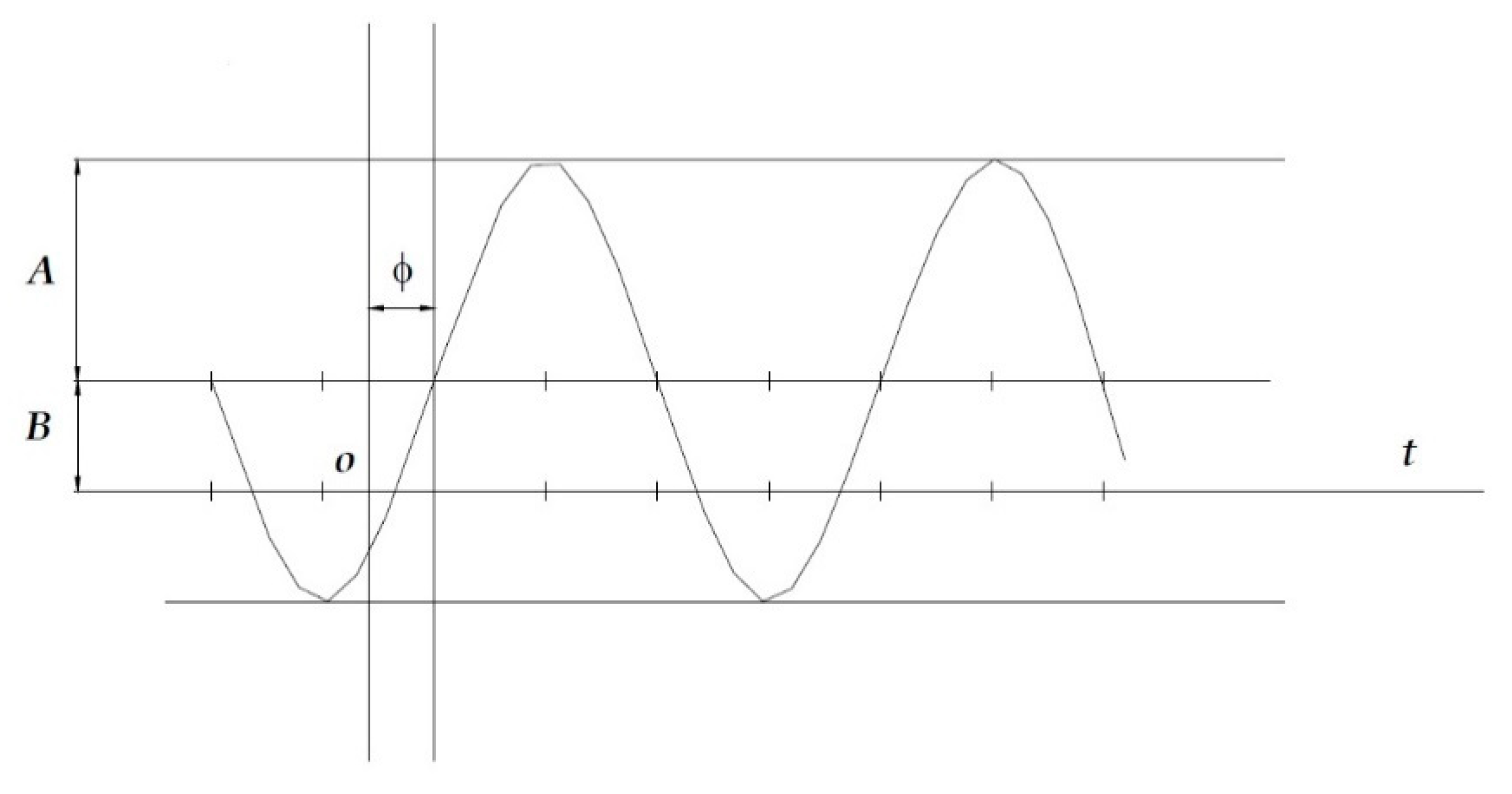
The function (Figure 13) that describes the movement of a simple pendulum (simple periodic movement or simple harmonic movement) is [41]
where A is the amplitude of the periodic movement and Φ is the offset.
y (t) = A sin (ωt + Φ)
For the pendulum to start moving at its point of maximum amplitude (Φ = ± 90°), and since the pendulum must mark seconds, ω must be 180°/s.
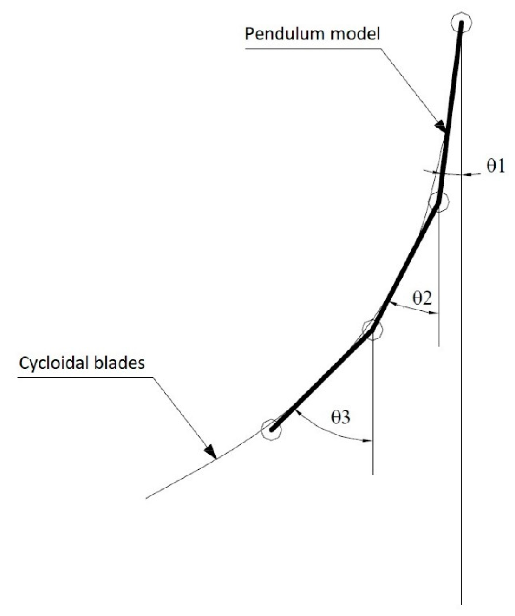
In this case, the chain of seven links has been modelled as a composite pendulum, in which each link describes a simple periodic movement with respect to the previous link. Therefore, the angular functions that simulate the movement of these links are
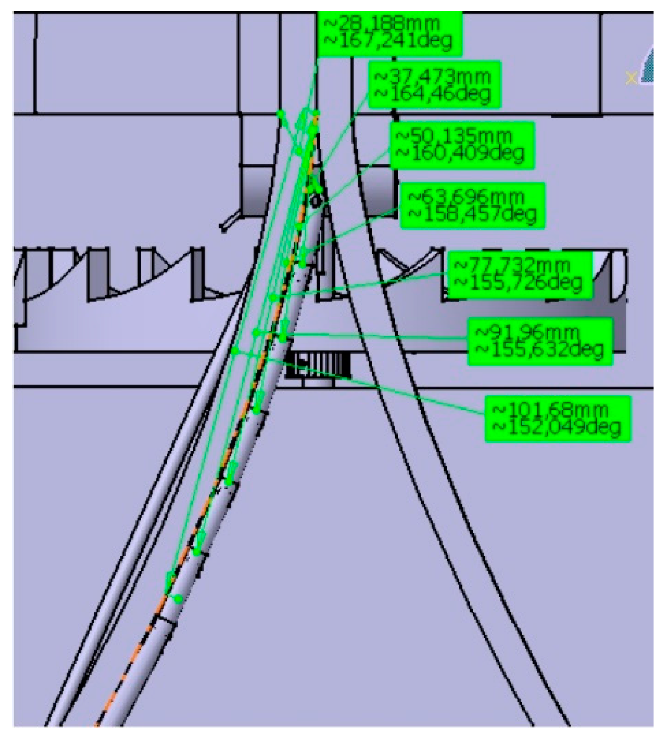
where j is a link and i is the link immediately before. In order to fully define the links, it suffices to measure the angles with respect to the vertical in the initial position of tangency to the cycloidal blade (Figure 14 and Figure 15).
For the first link: θ1 (t) = θ1 sin (180t − 90) + θ1
For the remaining links: θj (t) = (θj − θi) sin (180t − 90) + (θj − θi)
Therefore, the laws that describe the movement of the links are:
θ1 (t) = (180 − 167.241) sin (180t − 90) + θ1 = 12.759 sin (180t − 90) + θ1
θ2 (t) = (167.241 − 164.460) sin (180t − 90) + θ1 = 2.781 sin (180t − 90) + θ1
θ3 (t) = (164.460 − 160.409) sin (180t − 90) + θ1 = 4.051 sin (180t − 90) + θ1
θ4 (t) = (160.409 − 158.457) sin (180t − 90) + θ1 = 1.952 sin (180t − 90) + θ1
θ5 (t) = (158.457 − 155.726) sin (180t − 90) + θ1 = 2.731 sin (180t − 90) + θ1
θ6 (t) = (155.726 − 155.632) sin (180t − 90) + θ1 = 0.094 sin (180t − 90) + θ1
θ7 (t) = (155.632 – 152.049) sin (180t − 90) + θ1 = 3.583 sin (180t − 90) + θ1
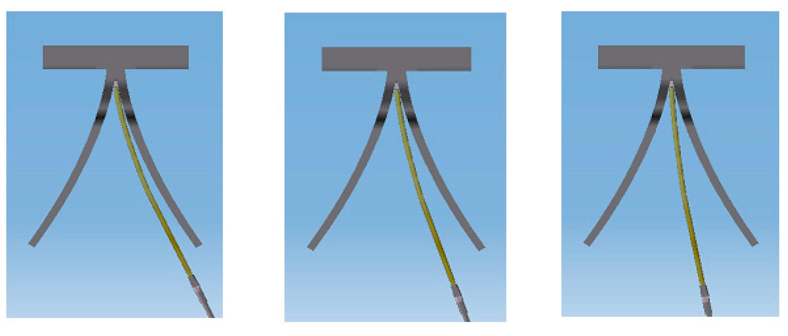
Finally, the process that follows is analogous to the previous process: In the simulation with commands a simulation is edited, and a film is then created or a video is generated. As can be observed in Figure 16, the string is curved before reaching the cycloidal blade, and precisely at the moment of arrival it adopts the shape of the blade, which represents a good approximation.
In the screenshots of the animation of Figure 16, the good approximation of this model can be appreciated: The chain (simulated string) is curved before reaching the cycloidal blade, and, exactly at the moment of arrival, its form is adopted. Although the chain does not move exactly like a string, the pendulum shaft carries the necessary movement to regulate the march of the clock. The reason why a greater number of links was not been chosen, which in principle would appear to guarantee a greater reliability of the model, lies in dimensional and geometric causes. From the dimensional point of view, the pendulum section that was represented (which was small in size), could not be easily represented with more than seven links, while from the geometric point of view, seven links sufficiently rectified the cycloid, a curve to which the pendulum had to adapt geometrically. Thus, seven links provides a working scenario of relative comfort and, as seen in the videos and animations obtained, the pendulum describes the cycloid very closely.
Furthermore, the kinematic relationships between the various gears are established by their transmission ratios and it is, therefore, only necessary to establish motion simulation functions for the remaining degrees of freedom. Once these degrees of freedom have been set, the clock can then be simulated and various animations of its operation can be generated.
5. Conclusions
In this article, the three-dimensional modelling of the isochronous pendulum clock of Christiaan Huygens is presented, together with the kinematic simulation of the pendulum using the CATIA V5 software.
The 3D model of the isochronous pendulum clock has been obtained with exactly the same proportions as those described in the work Horologium Oscilatorium, thanks to the sizing criteria adopted. However, the only information available regarding the operation of the pendulum clock appears as a brief description of the parts that compose it, the number of teeth of each wheel, the speed at which each axle should move, and the dimensions that the pendulum should have to mark the seconds. There is no information regarding the shape or dimensions of each piece, and hence the design proposed in this research has been created with only the graphic information available in Figure 1. Specifically, given the absence of detailed information regarding the dimensions of the elements, it has been assumed that the gear train as a whole measured vertically one third or, at most, half the length of the pendulum, which has enabled the primitive diameter of the largest wheel (crown wheel), C, of the gear train to be estimated as being 240 mm. From this dimension, it has been possible to define the dimensions of the rest of the wheels and the positioning of the axles, since the dimensioning of a pendulum clock is totally parametric, and depends solely on the length of the pendulum, which univocally implies a relationship of gears.
On the other hand, the main challenges faced in this investigation include the design of the gears of different tooth profiles, the design of the two cycloidal blades, the simulation of the pendulum movement, and, especially, the behaviour of the strings that support the bob of the pendulum. Moreover, one of the main limitations is that presented by CATIA V5 for the modelling of flexible elements such as strings, an inconvenience successfully resolved by approaching the string as a simple chain of seven links that behave as a composite pendulum. The rationale for choosing the number of links lies in dimensional and geometric causes. From the dimensional point of view, the pendulum section that was represented (which was small in size), could not be easily represented with more than seven links, while from the geometric point of view, seven links sufficiently rectified the cycloid, a curve to which the pendulum had to adapt geometrically.
The kinematic simulation of the pendulum was also performed, whereby the exactitude of the clock in the measurement of time was verified and the pendulum was described with close approximation to the cycloid. Furthermore, thanks to CAD and kinematic simulation techniques, it has been possible to understand and interpret the operation of Huygens’s isochronous pendulum clock, which in turn has enabled virtual recreations to be generated that can serve as educational tools in the museum of Science History, and has facilitated the dissemination of technical historical heritage. Moreover, future uses may involve the development of applications of virtual reality and augmented reality, the incorporation of the WebGL model into a website, and the ability to print in 3D using additive manufacturing techniques.
Author Contributions
Investigation, J.I.R.-S. and F.J.G.-C.; Methodology, F.J.G.-C. and G.D.R.-C.; Validation, F.J.G.-C.; Writing—original draft, J.I.R.-S. and F.J.G.-C.; Writing—review & editing, J.I.R.-S., F.J.G.-C. and G.D.R.-C. All authors have read and agreed to the published version of the manuscript.
Funding
This research received no external funding.
Acknowledgments
We sincerely appreciate the work of the reviewers of this manuscript.
Conflicts of Interest
The authors declare there to be no conflicts of interest.
References
- Baillie, G.H. Huygens’ pendulum clock. Nature 1941, 148, 412. [Google Scholar] [CrossRef]
- Lepschy, A.M.; Mian, G.A.; Viaro, U. Feedback-control in ancient water and mechanical clocks. IEEE Trans. Educ. 1992, 35, 3–10. [Google Scholar] [CrossRef]
- Senator, M. Synchronization of two coupled escapement-driven pendulum clocks. J. Sound Vibr. 2006, 291, 566–603. [Google Scholar] [CrossRef]
- Rojas-Sola, J.I.; De la Morena-De la Fuente, E. The Hay inclined plane in Cooalbrookdale (Shropshire, England): Geometric modeling and virtual reconstruction. Symmetry 2019, 11, 589. [Google Scholar] [CrossRef] [Green Version]
- Rojas-Sola, J.I.; Galán-Moral, B.; De la Morena-De la Fuente, E. Agustín de Betancourt’s double-acting steam engine: Geometric modeling and virtual reconstruction. Symmetry 2018, 10, 351. [Google Scholar] [CrossRef] [Green Version]
- Rojas-Sola, J.I.; De la Morena-de la Fuente, E. Digital 3D reconstruction of Agustín de Betancourt’s historical heritage: The dredging machine of the port of Krondstadt. Virtual Archaeol. Rev. 2018, 9, 44–56. [Google Scholar] [CrossRef] [Green Version]
- Rojas-Sola, J.I.; De la Morena-de la Fuente, E. Geometric modeling of the machine for cutting cane and other aquatic plants in navigable waterways by Agustín de Betancourt y Molina. Technologies 2018, 6, 23. [Google Scholar] [CrossRef] [Green Version]
- Rojas-Sola, J.I.; De la Morena-de la Fuente, E. Agustín de Betancourt’s wind machine for draining marshy ground: Approach to its geometric modeling with Autodesk Inventor Professional. Technologies 2017, 5, 2. [Google Scholar] [CrossRef] [Green Version]
- Río-Cidoncha, G.; Martínez-Palacios, J.; González-Conde, L. Torriani’s mechanical device for cartying water to Toledo. Ing. Hidráulica Mex. 2008, 23, 33–44. [Google Scholar]
- Pennestri, E.; Pezzuti, E.; Valentini, P.P.; Vita, L. Computer-aided virtual reconstruction of Italian ancient clocks. Comput. Animat. Virtual Worlds 2006, 17, 565–572. [Google Scholar] [CrossRef]
- Herrmann, J. Atlas de Astronomía; Alianza: Madrid, Spain, 1987. (In Spanish) [Google Scholar]
- Moore, P. Astronomía; Vergara: Barcelona, Spain, 1963. (In Spanish) [Google Scholar]
- Clagett, M. Ancient Egyptian Science: Calendars, Clocks, and Astronomy; American Philosophical Society: Philadelphia, PA, USA, 1995; Volume 2. [Google Scholar]
- Arago, F. Grandes Astrónomos Anteriores a Newton; Espasa-Calpe: Buenos Aires, Argentina, 1962. (In Spanish) [Google Scholar]
- Model of Huygens’ Pendulum Clock, as Illustrated in His ‘Horologium’ of 1658. Available online: https://collection.sciencemuseumgroup.org.uk/objects/co817/model-of-huygens-pendulum-clock-as-illustrated-in-his-horologium-of-1658-pendulum-clock-reconstruction (accessed on 24 December 2019).
- Tait, H. Clocks and Watches; Harvard University Press: London, UK, 1983. [Google Scholar]
- Wenham, E. Old Clocks; Spring Books: London, UK, 1951. [Google Scholar]
- Britten, F.J. Watch & Clockmakers’ Handbook. Dictionary and Guide; Antique Collectors´ Club Ltd.: Suffolk, UK, 1993. [Google Scholar]
- Bennett, M.; Schatz, M.F.; Rockwood, H.; Wiesenfeld, K. Huygens’s clocks. Proc. R. Soc. A 2002, 458, 563–579. [Google Scholar] [CrossRef]
- Klarreich, E. Huygens’s clocks revisited. Am. Sci. 2002, 90, 322–323. [Google Scholar]
- Huygens, C. Horologium. 1658; An English Translation Together with the Original Latin Text in Facsimile by Ernest, L. Edwardes; Antiquarian Horological Society: Ticehurst, UK, 1970. [Google Scholar]
- Edwardes, E.L. The Story of the Pendulum Clock; Sherratt and Son: Altrincham, Manchester, UK, 1977. [Google Scholar]
- Huygens, C. Horologium Oscillatorium, siue, De motu Pendulorum ad Horologia Aptato Demonstrationes Geometricae; Facsimile Reprint of the Text in Latin of Paris: Apud, F. Muguet, 1673; Culture et civilisation: Bruxelles, Belgium, 1966. [Google Scholar]
- Huygens, C. Horologium Oscillatorium; An English Facsimile Reprint of the 1673 Paris Edition; Dawsons: London, UK, 1966. [Google Scholar]
- Huygens, C. Christiaan Huygens’ the Pendulum Clock or Geometrical Demonstrations Concerning the Motion of Pendula as Applied to Clocks; Translated into English of Horologium Oscillatorium with Notes by R.J. Blackwell and Introduction by H.J. Bos; The Iowa State University Press: Ames, IA, USA, 1986. [Google Scholar]
- Popular Mechanics: Leonardo da Vinci’s Mechanical Lion. Available online: https://www.popularmechanics.com/technology/a29020685/leonardo-da-vinci-mechanical-lion-display (accessed on 24 December 2019).
- Betancourt’s Project. Available online: http://fundacionorotava.es/betancourt/machines (accessed on 24 December 2019).
- Juanelo Turriano’s Device to Raise the Water from the Tagus River to the City of Toledo (Spain). Available online: https://www.youtube.com/watch?v=_qTYt6drnOU (accessed on 24 December 2019).
- Antelo’s Clock: The Clock of the Cathedral of Santiago (Spain). Available online: https://parpatrimonioytecnologia.wordpress.com/2016/05/23/el-reloj-de-antelo-santiago-de-compostela-modelado-texturizado-y-visor-3d-galicia100/#more-2409 (accessed on 24 December 2019).
- Virtual Reconstruction of the Visigoth Church of Santa María de Melque (Toledo, Spain). Available online: https://www.artstation.com/artwork/v1DD0d (accessed on 24 December 2019).
- Virtual Reconstruction of the Church of San Agustín de la Laguna (Tenerife, Spain). Available online: https://www.youtube.com/watch?v=QEM_ZV3vLPU&feature=emb_title (accessed on 24 December 2019).
- Cozzens, R. Advances CATIA V5 Workbook: [Releases 8 & 9]; Schroff Development Corporation: Mission, KS, USA, 2002. [Google Scholar]
- Saorin, J.L.; Lopez-Chao, V.; De la Torre-Cantero, J.; Diaz-Aleman, M.D. Computer-aided design to produce high-detail models through low cost digital fabrication for the conservation of aerospace heritage. Appl. Sci. 2019, 9, 2338. [Google Scholar] [CrossRef] [Green Version]
- Rojas-Sola, J.I.; De la Morena-de la Fuente, E. The Hay inclined plane in Coalbrookdale (Shropshire, England): Analysis through computer-aided engineering. Appl. Sci. 2019, 9, 3385. [Google Scholar] [CrossRef] [Green Version]
- Rojas-Sola, J.I.; De la Morena-de la Fuente, E. Agustin de Betancourt’s double-acting steam engine: Analysis through computer-aided engineering. Appl. Sci. 2018, 8, 2309. [Google Scholar] [CrossRef] [Green Version]
- Tashi; Ullah, A.M.M.S.; Watanabe, M.; Kubo, A. Analytical point-cloud based geometric modeling for additive manufacturing and its application to cultural heritage preservation. Appl. Sci. 2018, 8, 656. [Google Scholar] [CrossRef] [Green Version]
- Pezzano, P.; Klein, A. Serie Elementos de Máquina: Engranajes y Poleas; Librería el Ateneo: Buenos Aires, Argentina, 1980; Volume III. (In Spanish) [Google Scholar]
- Carrera, T. Engranajes: Trazado Teórico y Práctico. 1ª y 2ª Parte; Carrera Soto: Sevilla, Spain, 1987. (In Spanish) [Google Scholar]
- Merrit, H.E. Gear Engineering; John Wiley & Sons: New York, NY, USA, 1971. [Google Scholar]
- Litvin, F.L. Gear Geometry and Applied Theory; Prentice Hall: Englewood Cliffs, NJ, USA, 1994. [Google Scholar]
- Maiztegui, A.P.; Sábato, J.A. Introducción a la Física; Kapeluz: Buenos Aires, Argentina, 1966. (In Spanish) [Google Scholar]
- GrabCAD: Free CAD Library. Available online: https://grabcad.com/library (accessed on 24 December 2019).
- Thingiverse: Models. Available online: https://www.thingiverse.com/explore/newest/models (accessed on 24 December 2019).
Figure 1.
Isochronous pendulum clock of Christiaan Huygens according to Horologium Oscillatorium.

Figure 2.
Front view of the 3D CAD model with an indication of all wheels and the pinion, as well as the main parts.
Figure 2.
Front view of the 3D CAD model with an indication of all wheels and the pinion, as well as the main parts.

Figure 3.
Tracing the cycloid with CATIA V5 according to Horologium Oscillatorium and a 3D CAD model.
Figure 3.
Tracing the cycloid with CATIA V5 according to Horologium Oscillatorium and a 3D CAD model.

Figure 4.
Generation of the cycloid by means of a spline.

Figure 5.
Cycloidal blade.

Figure 6.
Pendulum between cycloidal blades according to Horologium Oscillatorium.

Figure 7.
Pendulum geometry tree.

Figure 8.
Rendering of the chain with a real string appearance.

Figure 9.
Rendering of the complete assembly of the isochronous pendulum clock.

Figure 10.
Command simulation.

Figure 11.
Detail of the chain clamp between the cycloidal blades.

Figure 12.
Position of the links tangential to the cycloid blade.

Figure 13.
Function describing the movement of the simple pendulum.

Figure 14.
Modelling of the seven-link chain as a composite pendulum.

Figure 15.
Values of the angles that form the links with respect to the vertical in their initial position of tangency to the cycloidal blade.
Figure 15.
Values of the angles that form the links with respect to the vertical in their initial position of tangency to the cycloidal blade.

Figure 16.
Sequence of chain curvature (simulated string) before reaching the cycloidal blade.


Table 1.
Main dimensional values determined for all wheels and pinion.
| Wheels | Number of Teeth | Primitive Diameter (m) | Modulus | Pressure Angle (°) |
|---|---|---|---|---|
| S (Pinion) | 6 | 0.012 | 2 | 26 |
| G & E | 8 | 0.024 | 3 | 23 |
| I | 24 | 0.060 | 2.5 | 14.5 |
| Y & B | 30 | 0.078 | 2.6 | 14.5 |
| H | 48 | 0.120 | 2.5 | 14.5 |
| F | 48 | 0.144 | 3 | 23 |
| P | 72 | 0.144 | 2 | 26 |
| C (Crown wheel) | 80 | 0.240 | 3 | 23 |
© 2020 by the authors. Licensee MDPI, Basel, Switzerland. This article is an open access article distributed under the terms and conditions of the Creative Commons Attribution (CC BY) license (http://creativecommons.org/licenses/by/4.0/).
Share and Cite
MDPI and ACS Style
Del Río-Cidoncha, G.; Rojas-Sola, J.I.; González-Cabanes, F.J. Computer-Aided Design and Kinematic Simulation of Huygens’s Pendulum Clock. Appl. Sci. 2020, 10, 538. https://0-doi-org.brum.beds.ac.uk/10.3390/app10020538
AMA Style
Del Río-Cidoncha G, Rojas-Sola JI, González-Cabanes FJ. Computer-Aided Design and Kinematic Simulation of Huygens’s Pendulum Clock. Applied Sciences. 2020; 10(2):538. https://0-doi-org.brum.beds.ac.uk/10.3390/app10020538
Chicago/Turabian StyleDel Río-Cidoncha, Gloria, José Ignacio Rojas-Sola, and Francisco Javier González-Cabanes. 2020. "Computer-Aided Design and Kinematic Simulation of Huygens’s Pendulum Clock" Applied Sciences 10, no. 2: 538. https://0-doi-org.brum.beds.ac.uk/10.3390/app10020538
Note that from the first issue of 2016, this journal uses article numbers instead of page numbers. See further details here.