Modeling and Simulation of a Flexible Manufacturing System—A Basic Component of Industry 4.0


Faculty of Technological Engineering and Industrial Management, Transilvania University of Brasov, 500036 Brasov, Romania
*
Author to whom correspondence should be addressed.
Appl. Sci. 2020, 10(22), 8300; https://0-doi-org.brum.beds.ac.uk/10.3390/app10228300
Submission received: 30 September 2020
/
Revised: 14 November 2020
/
Accepted: 19 November 2020
/
Published: 23 November 2020
(This article belongs to the Special Issue Advanced Manufacturing Technologies and Their Applications)
Abstract
:The field of Flexible Manufacturing Systems (FMS) has seen in recent years a dynamic development trend and can now be considered an integral part of intelligent manufacturing systems and a basis for digital manufacturing. Developing the factory of the future in an increasingly competitive industrial environment involves the study and analysis of some FMS key elements and managerial, technical, and innovative efforts. Using a new approach, thus paper presents a material flow design methodology for flexible manufacturing systems in order to establish the optimal architecture of the analyzed system. The research offers a solution for modeling and optimizing material flows in advanced manufacturing systems. By using a dedicated analysis and simulation software, the structure of the system can be established and specific technical and economic parameters can be determined for each processing and transport capacity. Different processing scenarios will be evaluated through virtual modeling and simulations in order to increase the performance and efficiency of the system. Thus, an interactive tool useful in the design and management of flexible manufacturing lines will be developed for companies operating in the industrial sector. The application of this paper is mainly in the field of development of intelligent manufacturing systems, where the control system will make and use simulations in order to analyze current parameters and to predict the future.
1. Introduction
The integration of intelligent machine tools and industrial robots in flexible production systems and the development and use of new software for simulating, monitoring, and controlling production processes require profound transformations in the industry. Given the complexity of these systems, aiming at increasing production capacity in the context of diversifying production, shortening the life cycle of products, and increasing competitiveness, the strategic decision to implement a Flexible Manufacturing System (FMS) in an intelligent manufacturing system is currently an important goal.
The development of the IT sector has led in recent years to the development of integrated production systems and advanced production technologies, where a special place is given to the flexible manufacturing system. Increasing the competitive edge, the performance of companies, especially in the industrial sector, requires innovations and continuous adaptations of production systems and business processes for products and services [1,2].
In order to respond effectively to new market requirements, companies need to rethink their entire production process by implementing digital technologies [3,4]. The digital transformation will improve the competitiveness of industrial organizations while strengthening their ability to make optimal decisions. Kaltum et al. (2016) considered that “digital transformation is a profound change and accelerates business activities, processes, competencies, and models to fully exploit the changes and opportunities in digital technology and its impact on society in a strategic and prioritized way” [5]. Through a new approach [6], based on a review of current literature, Bican et al. (2020) proposed and developed a conceptual framework for integration in the digital transformation process of several “digital” terms not connected until now (digital readiness, digital technology, digital business models, and digital entrepreneurship). The aim was to provide companies with a uniform framework of sustainable development and digital transformation [7].
Human creativity, correlated with the desire to permanently raise the standard of living, is the basis for the development of a society. Seen as a new paradigm in the field of manufacturing, the concept of Industry 4.0 creates an opportunity to revamp and relaunch production by means of a new vision of a company and the digitization of current production systems.
The new Industry 4.0 concept consists of developing digital manufacturing in the enterprise by creating smart grids across the entire value chain, which can independently control each other, networks formed by interconnecting intelligent machines, and advanced manufacturing systems and products. Tools and embedded components are Industry 4.0 concepts: Cyber-Physical Systems (CPS), Internet of Things (IoT), cloud computing, robotics, systems based on artificial intelligence, and cognitive computation [8,9,10]. Studies and research developed in recent years [11] bring important scientific contributions in the field of mechatronics and robotics, presenting advanced methods of design, simulation modeling, and control in complex robotics systems.
In a recent and complex study, the authors Culot, G. et al. (2020) [12] identified and analyzed nearly 100 Industry 4.0 definitions and related concepts. The consistency of the study is given by the review of several academic publications and the consultation of some governmental organizations and of some companies specialized in the field. The stated goal was to provide several researchers approaching Industry 4.0 with a common basic framework for future research on tackling the phenomenon in its many facets.
The authors Arnold and Kiel (2016) considered that “the new paradigm of digitization and connected manufacturing called Industry 4.0 brings profound transformations on factories, through intelligent and autonomous production” [13]. The applicability of Industry 4.0 in the field of manufacturing aims at industrial development, simultaneously with increasing competitiveness of companies, as highlighted in the paper [14,15]. This paper focuses on the development of the fundamental concept of Industry 4.0 and presents a current stage of development of manufacturing systems, identifying the research gaps that exist in the operation of FMSs. It also presents a framework model with several layers of implementation of Industry 4.0 and the requirements of this system.
Recent research [16,17,18] analyzes the perception of different companies on the opportunities and challenges of implementing Industry 4.0, depending on their specificities. The authors of the paper [19] emphasized the need to develop advanced technologies, reconfigurable machine tools (RMT), with a high degree of flexibility integrated in manufacturing systems and to develop models of numerical simulations on production lines.
A basic component of Industry 4.0 is the flexible manufacturing system (FMS), an advanced production system that interconnects machines, workstations, and logistics equipment, the entire manufacturing process being coordinated with the computer. This manufacturing system is intended for manufacturing tasks of large typological diversity, for high complexity, for ensuring time delivery, and for minimal manufacturing costs, while production is unpredictable, being organized in small batches, with frequent changes.
The experience of large industrial companies has shown that they have gradually reached advanced manufacturing systems, going through a series of steps: simplification, integration, and automation. Two important elements, “flexibility” and “adaptability”, characterize these systems with the ability to quickly adapt to an environment in which continuous, variable, and unpredictable changes take place. In addition, FMS is considered the only manufacturing system that has resolved the contradiction over time between flexibility–adaptability–productivity by responding effectively to market requirements [20,21]. Important contributions in the current development of the flexible manufacturing have been made by Diaz, Ocampo-Martinez, and Olaru (2020) [22] by developing a dual-mode control strategy based on two control approaches to minimize the energy consumption of flexible manufacturing systems without affecting their productivity. The authors consider that “the manufacturing industry is moving towards intelligent production, in which both energy efficiency and flexibility are some of the main objectives of this transformation”. In the paper [23], the authors Seebacher and Herwig (2018) considered flexibility to be a “key objective of many manufacturing systems” and presented a procedure for assessing flexibility and calculation steps.
From a systemic perspective, FMS can be assimilated with Cyber-Physical Systems (CPS) [24] that have the possibility, at higher stages of organization (CIM (Computer Integrated Manufacturing)) to self-regulate and lead to the optimization of manufacturing processes. By integrating elements of artificial intelligence into their structure, FMSs, as intelligent manufacturing systems, can be considered a part of the new concept structure, the Industry 4.0.
In their evolution [9,20,25], there can be noticed efficient flexible systems implemented for processing/assembly and many failures, determined most of the times by an over evaluation of technical solutions, by the impossibility of managing efficiently these systems which are extremely complex, and by the huge investment they need.
Following a review of the literature in the field [26,27], it can be stated that adoption of modeling and simulation techniques and their implementation in the industrial sector in order to digitize production and business processes is done differently; there is no an unanimously accepted methodology. In the literature, in recent years, papers have been published on modeling and simulating systems with discrete events, including FMS [28,29], but approaches to the analysis of complex phenomena are only intuitive, as there are no mathematical models for configuring these systems.
In this context, the research undertaken in this scientific paper is focused on the study and analysis of FMSs in order to know their behavior and performance as well as possible, based on the establishment of mathematical models of configuration and simulation, for further integration into intelligent manufacturing systems. Lack of consecrated mathematical models in the design of flexible fabrication systems makes the creation of such systems difficult, with consequences upon their performance.
While being imposed as the new property of fabrication systems, “flexibility”, some conception errors may occur and designers cannot anticipate precisely the optimal flexibility degree. As far as the approach method of the large topic of flexible fabrication systems is concerned, it should be noted that there still are different methods and interpretations, but no model has been imposed as proven.
The concept of flexibility involves the complete study of manufacturing systems, which can be achieved only from the considerations of a complex system. By analyzing the system in such a conception, it is possible to establish the conditions by which to meet the requirements of flexibility and automation. It should be noted that the study of the flexibility of the manufacturing system derived the study requirement for the component subsystems. Obviously, for the flexibility of the system, the flexibility of the subsystems that compose it will be defining. At the moment, the flexible manufacturing systems operation modeling represents the most dynamic and controversial research area. The need for and opportunity of research studies are oriented, in recent years, to intelligent production as an emerging form of production, and the application of the concept of Industry 4.0 also results from the study of representative works in the field [22,30,31,32]. Integrated platforms, sensors, artificial intelligence, and advanced manufacturing systems are presented. However, it is emphasized [30] that there are still phenomena to be investigated, in particular, by finding appropriate mathematical modeling techniques in the design and configuration of current manufacturing systems. So far, there is no formal method, no generalized design methodology for setting up an FMS.
Mathematical modeling of complex systems and flexible fabrication systems as well leads in general to large-scale models [33,34]. There are problems concerning the model scale, more precisely, even if this model is very large, it cannot include all the interactions between component subsystems and between those systems and the exterior environment. If a larger model is to be realized and its precision degree must be high, it can be difficult to be completed and the relevance of the problems to be solved decreases, a fact which is mentioned in the literature as well [35].
This paper proposes a mathematical model for the analysis of flexible manufacturing systems by decomposing the complex system and by coupling the component subsystems using the matrix mathematical calculation. Based on this model, the configuration and simulation of the system operation was performed in order to identify the problems that appear, as a result of the random and unpredictable variables that act on the system. Given the whole issue of flexible manufacturing that has not yet been fully explained and taking into account the above observations, it may be the case to start the research in this direction.
Simulation studies of different phenomena, processes, and complex systems represent an important objective of scientific research [36]. Virtual reality (VR) and augmented reality (AR) simulations are key technologies in Industry 4.0, which allow testing and studying new processes before implementing them. A framework for modeling industrial processes is presented in [37], a simulator for the aeronautical industry being developed. Solving some difficult problems in the area of production scheduling in advanced manufacturing systems by mathematical modeling is performed in the papers [38]. Different examples of simulations of production processes using modern software are presented in the literature [39,40,41,42], the aim being to streamline and to increase production by eliminating idle times. We can assume that there is currently no other “method” or “theory” that allows experimentation with a complex system before commissioning. A simulation model was developed as part of the study [43] that allows the identification of bottlenecks in manufacturing processes, as they have negative effects on real production lines in companies.
Simulation thus becomes an important and extremely efficient research method in the current context of manufacturing digitalization. Applied in production systems, simulation can provide answers to how they respond to the various variables and unpredictable situations that arise. Simulation models are usually used when it is impossible or very difficult to develop an analytical solution to a studied problem. Given the dynamic behavior of an FMS and the absence of “dedicated” analytical models for their design, analysis, and optimization, simulation is an appropriate method of solving difficult problems that occur in these complex systems [43].
This paper aims to analyze the technical and economic performance of a flexible manufacturing system using modeling and simulation techniques. By using a modern Tecnomatix Plant Simulation 15 software from Siemens Product Lifecycle Management Software Inc., Germany [44,45], a flexible manufacturing system is analyzed in order to identify malfunctions and to optimize the process.
2. Materials and Methods
The implementation and commissioning of a manufacturing system and, in particular, an FMS involves a large amount of f expenditures, and the expected economic level is difficult to specify. For this reason, both during the design of the structure of the flexible manufacturing system and in its operation, the modeling and simulation technique is used. This allows for reproduction or prediction of different aspects of the dynamic operation of an existing or future system by developing a mathematical model in order to optimally respond to the problems involved in its operation. Thus, modeling and simulation is considered an experimental and applied methodology that allows the development of studies on the following topics: describing the system behavior; developing theories and hypotheses for explaining the observed behavior; and using a model to analyze the following behavior or the effects produced by the changes in the system or by its operating procedures.
So far, the existence of asynchronous and concurrent events in a complex system, such as FMS, has made the number of its modeling techniques relatively small. However, the use of simulation techniques in the field of complex dynamical systems, including FMS, is currently widespread [46,47]. The evolution of the system over time can be described by complex algorithms or procedures, which best describe the operation in real time. The dynamic structure of the simulation introduces time into the operation of the model. This is necessary to place objects in real time and to allow progress in time from one state of the system to another state. Computer modeling and simulation allow the visualization and forecasting of the performance of a system with lower costs than when using other methods. Different processing scenarios through virtual modeling and simulations and the choice of the optimal variant are described in the paper [48].
The applicative character of the research consisted in real-time tracking of the process using the software package designed on a system designed and implemented as a modular system, based on mathematical and graphic-analytical models of sizing, configuration, optimization, and simulation [49].
2.1. Graphic-Analytical Model of FMS
In the basic literature of the FMS field [23,25,33,50,51], manufacturing flexibility expresses the capacity of the system to produce not only a typological diversity of products but also unpredictability and instability, reduced time delivery, small batch manufacturing, rapid response to changing market conditions, change in structure-insensitive manufacturing pregnancy, rapid reconfiguration of the system to change production volumes, and geometric configuration of the piece.
Flexible manufacturing systems (FMS) are oriented, open, deterministic, and complex systems. The study of such a system means to know the evolution in time of inputs/outputs and of the transfer of information. This is done using mathematical models. Developing a mathematical model consists in developing a system block diagram representation and of defining the analytical part, the graphic-analytical model developed for FMS. A system is generally defined as the set of components grouped by organizational rules which have a lot of functional relationships. The system is defined as consisting of three components: external environment (EE), composition (CS), and structure (ST).
The FMS graphic processing part revolution will be designed by highlighting the physical meaning of different types of variables involved in the system:
- Exogenous variables are variables for which behavior is dictated by external phenomena and events, variables through which the system can communicate with the external environment:
- Input variables (command) define inputs to the system (for which the values are given, known, and estimated).
- Output variables define the outputs from the system (resulting from processing).
- Disturbance variables external environmental influences on the system. The functional relationship (linked) between input and output variables can be expressed mathematically in the form of algebraic equations (inequalities), differential equations, integral equations, etc.
- Endogenous variables are those in which the behavior is dictated by the interior system phenomena and events and that describe its dynamics.
There are two such types of variables: state variables, defining the state of the system, and interaction variables (between subsystems), defining the links between subsystems.
In the external environment (outside the system EEo—exomedium), many outlets, objective functions—performance indicators (imposed, real parameters that are available) chosen from the sensitivity indicators—are found. At the output of the manufacturing system, products with determined configurations and properties, and auxiliary materials and waste are found. The energy consumed within the system during the process is released into the environment as heat. If the output size-power is considered as the default in the study of manufacturing systems, the output size-information, instead, has a special importance for the production management by expressing the real state of the system during the process evolution on which real-time and real-environment operative manufacturing management decisions are based.
Summarizing the above, it appears that the general function of a manufacturing system consists in transferring the information flow (IF) into a material flow (MF), using an energy flow (EF), so that the information creates an emerging property on input FM, transforming it into an output finished product (Pf) that can be sold on the market.
Knowing the overall system function, one can determine its structure, and their connecting and relating elements within the structure. For this, a time evolution analysis of the material, energy, and information flow on the transfer that is transferred is transformed in the manufacturing system from input to output. Finally, the overall structure of the flexible manufacturing system will be determined by allocating partial functions to some physical elements—FMS component subsystems such as machine tools, transmission, transformation and processing systems, handling, transport and storage elements, transmission and distribution of energy, and its transformation, etc. Then, the necessary links between them are established in order to achieve the overall system operation.
Input Dates and Variables
The complexity of a system is given by the number of components, the number and type of interactions, the set of system state, the nonlinearities type, and the number of inputs and outputs. During design, system decomposition S should be made in a minimum number (strictly necessary) of subsystems, so that each sub-model is globally optimal solvable. Process management subsystem (PrM) has the function of couplings coordinator between subsystems and of sharing the subsystem objectives. Coordination of interactions at the same hierarchical level is made by establishing relationships of priority between subsystems for which the number should be minimal. The processing subsystem (PrSb) has priority over other subsystems, followed by industrial logistics subsystem (ILSb) and the stocking/storage subsystem (STSb), then the measurement/control subsystem (MCSb), and ancillary subsystems (ASb).
The analyzed system is characterized by inputs (i) and outputs (o) and, therefore, by input data, output data, and information links. The system links with the external environment represent the so-called “external coupling” or “entourage”. External couplings can be found on the input, in the input external environment (EEe) and on the output, and in the output external environment (EMo). The input EEe contains “resources”, and the output EEo contains the system “target”. The dependency relations between external environment EEe (“resources”)–the system composition SC (“middle”)–external environment EEo (“target”) are shown in the figure above. For the studied case, the graphic-analytical model from Figure 1 was elaborated.
Inputs in a flexible manufacturing system that are found in the input external-environment (EEe) are the following: material flow (MF), informational flow (IF), energy flow (EF), and manpower (MP).
Outputs from the manufacturing system represent the output external environment (EEo) containing the following output flows: finished goods flow (strategic finished product for the company and finished parts for third parties); knowledge flow (know-how); waste flow (recoverable waste and residues); and secondary energy flow, formed by secondary recoverable energy and secondary dissipated energy.
A major influence on the evolution of the system in time has the appearance of random variables in the system, such as bottlenecks. They are unpredictable and require a probabilistic analysis. By simulation, they can be easily identified; then, by applying the optimization model, they can be eliminated, ensuring continuous flow operation and reducing losses on the manufacturing line.
2.2. FMS Structural Analysis
The analysis of flexible manufacturing systems is done from the point of view of system’s theory. The system is generally defined as the set of components grouped according to given ordering rules based on interaction relations. In structural analysis, two types of schemes are used: layout scheme and block scheme (structural). The layout of the system contains all the components of the system as elements and their relative arrangement in the plan, in real positions, without flows and relational connections. It is drafted using standardized or conventional symbols.
The study was performed for the integrated automated system presented in Figure 2, which is part of a flexible manufacturing system for processing bearing ring types of cylindrical parts that are to be developed in collaboration with the company [52].
The integrated automated manufacturing and assembly system in Figure 2 implements the following sequence of operations:
- -
- picking up semi-finished parts of rectangular shape from a warehouse;
- -
- feeding the parts in a in a CNC(Computer Numerical Control) milling machine with the help of an articulated robot;
- -
- processing the finished part;
- -
- extracting the finished part and putting it on a conveyor;
- -
- picking up the cylindrical part and putting it on the conveyor;
- -
- assembling with the help of a SCARA (Selective Compliance Assembly Robot Arm) robot;
- -
- putting the completed assembly in an automated warehouse with the help of a cartesian robot.
The system integrates advanced control techniques, as follows:
- -
- The pick-up of the parts by the robot from the feeding conveyor with cylindrical semi-finished products will be done on the basis of visual inspection while the parts are moving (on the go) depending on the “tracking”;
- -
- the free/occupied storage positions in the automated warehouse are indexed at the software level.
Decomposable Structural Diagram of the System
In the following, we shall develop a decomposed structural diagram of the analyzed FMS. Unlike the layout, it contains all system components (subsystems) conventionally represented by rectangles, conveniently arranged and not necessarily in the actual relative position, as well as all flows and relational connections (couplings) between all the component subsystems, explicitly and possibly not intersected.
The decomposable structural diagram corresponding to the considered system is presented in Figure 3. The diagram shows all the component subsystems, all inputs and outputs, and all couplings.
The diagram shows all the component subsystems, all inputs and outputs and, all couplings. The notations of FMS subsystems components correspond to the layout of the system. Thus, in the scheme of Figure 3, the FMS processing subsystems components of items were numbered from 1 to 7. The subsystem process management (PrM) coordinates all component subsystems: IR—Industrial robot; M—Machine tool; WD—Working device; StTL—Tool supply station; StLSf—Semi-finished delivery station; PrDg—Process Diagnosis; StEvFP—Finished product evacuation station. All information couplings are of a two-way type.
The symbols for simple and combined flows in the diagram are as described in Table 1.
The tool flow is also schematically represented, even if the issue of tools is not a distinct objective of this paper. In the diagram, for simplicity, the energy flow related to each subsystem was not rigorously represented, but it is known that any component of the FMS where a part is processed or transported is performed with energy consumption, therefore, by energy flow. It is considered that the energy system is central and common to all subsystems and that it exists and operates. Thus, the focus in the modeling and simulation stage of FMS was put on the material and information flows [53].
A useful tool in the analysis is the mathematical modeling of coupling the component subsystems, applied for the previously designed structure.
2.3. Mathematical Model of System Coupling
The mathematical model uses a block diagram for the representation of a system, where one can define input vector, output vector, and transfer function (expressing the dependence of output vector on the input vector and system structure). The structure of a system is given by the nature of its subsystems, their number, the nature, and the number of relationships that exist between subsystems.
There is a coupling relationship between two subsystems if at least one output of a system represents the input of the other system. The coupling of two systems represents the systemic connection between them, regardless of the material nature.
In the decomposable structural diagram in Figure 3, the pairs of input and output quantities in/from the subsystems were noted:
- -
- inputs (Xci), where (c) is the number of components and (i) is the number of coupling
- -
- outputs (Ypj), where (p) is component part number; (i) is the number of coupling; and p, q, i, and j ∈ N.
The system coupling can be in series or in parallel. The mathematical relation of coupling of two systems in series is characterized by Relation (1), in which
After drawing the decomposable structural scheme (based on the principle of decomposability and optimality) and the establishment and representation of couplings between subsystems, we move on to the next stage of determining coupling matrices and structure matrix.
2.3.1. System Coupling Matrix
Coupling matrices indicate the interactions in vectorial meaning from system S1 to the system S2 (S1 outputs connected to S2 inputs). By its elements, the coupling matrix expresses all couplings between the two subsystems.
For two systems S1 and S2 coupled in series, the coupling matrix (Kei), o (output), and i (input) will be an (m × n) sized matrix, with the following ordination:
Binary matrix. The matrix elements () are defined binary variables, according to Equation (3):
These elements describe the coupling states according to the following rules:
- If there are connections (couplings), then and
- If there are no connections (couplings), then and
- The rules were also established:
- when the connection between is defined;
- when the connection is undefined.
The resulting Equations (4) is as follows:
For a system of (r) order, consisting of (N) subsystems of (r + 1) orders, the maximum number of links (couplings) will be N(N − 1). Because many couplings are identical and repeated, in reality, the number of coupling is small. The structure of a system S of (r) order is given by the type and number of component subsystems as well as by the type and number of the relations existing between them.
Between two coupled subsystems (ordinates 1 and 2), the linking relationship will be as follows:
Writing coupling matrix can be made directly from the decomposable structural diagram or by separating each subsystem, therefore, by drawing component block diagrams. The following symbols are used for subsystems and for input (i) or output flows (s) (Table 2).
To write the coupling matrices, the block diagrams of the components were drawn using the decomposition methodology of the large system into subsystems. For the flexible manufacturing system analyzed, the result was 25 coupling matrices (Kci), making up the structure matrix (KSTR).
2.3.2. Structure Matrix of the System
The structure matrix is determined based on a decomposable structural diagram of the system (Figure 3) and includes all the couplings in the system. This matrix, together with the decomposable structural diagram, describes the organization and operation of flexible manufacturing systems for bearing ring manufacturing
The structure matrix (KSTR) is the matrix for which the elements are the coupling matrices (Kci) of all component subsystems in the lower levels and is a zero-diagonal dimension matrix (N × N).
The elements of the structure matrix exist if .
For example,
For the analyzed FMS (Figure 3), the following dimension structure matrix (N × N) resulted, where N = 7. The expressions of the coupling matrices corresponding to the decomposed structural diagram of the FMS were elaborated by the authors in previous papers [49].
Based on the decomposed structural diagram (Figure 3), it was possible to develop the model to be used for the simulation program, a program based on sets of rules for each subsystem (workstations, robots, conveyors, and storage). We have found that, of all the system components, those having the most couplings are the most complex components. From the decomposed structural diagram, it results that one of the most complex components subsystems is the industrial robot.
3. Simulation Model Results
Using the simulation techniques and the modern Tecnomatix Plant Simulation 15 software from Siemens [44], the operating processes of all FMS component subsystems could be visualized and analyzed for the case study considered, respecting the accuracy and taking into account calculation of the interaction between system components and the external environment. Thus, the evolution in time of the state of the system could be described as a dynamic system, being described as operating in a real environment.
Plant Simulation software from Siemens PLM(Product Lifecycle Management) [45] as an important tool in a digital factory allows dynamic, object-oriented simulation of complex systems with discrete events. The choice of the Tecnomatix Plant Simulation software took into account the possibility of applying it to the analyzed real issues. In the field of flexible manufacturing, several software packages (Arena Simulation Software, Rockwell Automation, Austin, TX, USA; FlexSim Software Products, Inc., Orem, Utah, USA; AutoMod Simulating Reality, Salt Lake City, Utah, USA; Simul 8, Corporate Headquarters Boston, MA, USA; Enterprise Dynamics and ShowFlow, INCONTROL Simulation Solution, Utrecht, The Netherlands Matlab Simulink, The MathWorks, Inc., USA) [48,54,55] are known and implemented.
The simulation allowed for definition of the initial conditions: the states of the system components at the start of the simulation, the positions of the system components, the analysis of the system disturbances, and the final states at the exit from the system. Thus, it was possible to control at any time during the simulation the state of the components of the analyzed flexible manufacturing system. Also, the presented simulation program performs the animation function of the movements performed within the FMS.
The simulation model was based on the whole theoretical concept developed in the previous paragraphs. Its validation was done by computer simulation for real physical applications, consisting of the complete processing of several types of parts from the family of parts circulating in the process. Following simulation of the FMS operation, the validity of the models, their utility in design and the management of processes in the environment and real time resulted.
3.1. Design of the Simulation Model—Case Study
The design of the simulation model and the actual simulation were performed in order to verify and confirm the theoretical model, using a real case study, in the manufacture of bearing ring type cylindrical parts, requiring adequate knowledge of the modelled object. The model was designed according to the events and processes that take place in the system and the technological operations (processing of flat surfaces, processing of running channels, turning, grinding, and superfinishing/honing) needed to achieve the analyzed part and the constraints imposed on manufacturing.
The use of modern state-of-the-art software in designing and studying advanced production systems represents an important step towards digitizing the production and integrating it into the industry of the future: Industry 4.0. Using Tecnomatix/Siemens Product Lifecycle Management Software Inc. (2015) [44], the plant simulation module performed the system simulation with discrete events on a case study—a flexible manufacturing system (Figure 4).
The goal was to achieve the simplest possible model of the designed system. The manufacturing system model (Figure 4) is based on an example of a real production department by using the Tecnomatix Plant Simulation software/Siemens, the input data being collected directly from the respective process. Data on costs, energy consumption, and labor were not taken into account.
The simulation technique can graphically model asynchronous/synchronous concurrent events, manufacturing processes, real-time control systems, and real-time decision concepts within a flexible manufacturing system. The simulation model presents a detailed description of the alternative of flexible manufacturing systems considered, having the role of reproducing the dynamic performances of the system. The relevant evaluation criterion (average waiting time of the parts in the system) is then deduced from these dynamic observations.
The manufacturing flow was organized on the principle of workstation compatibility. Following this criterion, the principle of technological compatibility and functional compatibility as well as the related information exchange were respected.
Finally, the general structure of the FMS was determined by allocating partial functions to some physical elements—component subsystems: machine tools, information transmission, transformation and processing stations, elements for handling, transport, storage, energy transmission and distribution systems, and its transformation, etc. Then, the necessary connections between them were established in order to obtain the general system operation.
The analyzed process contains 8 workstations and handling elements of industrial robot type and transport with conveyor as well as storage elements at the system entrance and exit. Only one work shift was considered for the analysis. Logistics and equipment such as loading station, conveyor, industrial robot, sorting station, and loading station were also designed and integrated in the system.
3.2. Simulation Results
Based on the analytical model previously developed, a simulation model of the system operation was made, using the simulation software from Tecnomatix Plant Simulation, with a 2D simulation sequence being presented in Figure 5. A digital model makes it possible to perform several scenarios, tests, or experimentation both in the design phase and in the implementation phase without directly intervening in the production process. The simulation analysis tools offered by this software allowed quick and easy interpretation of the simulation results. The simulations performed indicated the bottlenecks of the entire production process and allowed the experimentation of optimizations to ensure continuous flow in manufacturing.
The input database contains the following information about the analyzed system:
- production volume, expressed as a number of processed parts;
- generalized technological sheets for processing of the representative items to represent the generalized item of the manufacturing task (family of parts) taken into account;
- types of technological handling and processing equipment, and other specific FMS components;
- typological diversity of the items processed in the system; and
- frequency of visits of any item to any workstation in the system.
Identification of Production Bottlenecks
A major influence on the system evolution is represented by the development of disturbances (functional or organizational bottlenecks, blocking times (tbi), auxiliary times (taux i),adjustment times (tad i), the number of blockage cases (nbi), the frequency of blockages (fbi), the number of workstations (qk), blocking probability (pi), asynchrony size (tik), etc., that occur in the system and can be found in the disturbing external environment (EEd). Unlike the input quantities in the system, for whcich the influence can be modeled by various methods, disturbances cannot be modeled and they influence the output sizes in a way that we cannot control because they are unpredictable, random, and variable in time. To prevent the disturbances from causing unwanted developments of the output sizes, the system is provided with a feedback loop.
For the analyzed manufacturing system, the bottlenecks in production were identified. The diagram in Figure 6 shows the results collected during the simulation. Advanced analytical tools, such as bottlenecks analysis, statistics, and diagrams, can be used to perform different production scenarios. In this way, the resources at the level of the manufacturing process can be optimized.
The simulation results showed that it is possible to increase the reduced capacity of the process by adding another parallel workstation for the operation that induces the biggest bottleneck. In the analyzed process, it is the grinding station of the bearing rings (“Parallel Station” in Figure 6).
In Figure 6, small charts are shown over each station showing the amount of time that the station spends in each state. The diagram can be analyzed as time spent in each work station in each state, with the following colors:
- gray bar—waiting, green bar—working, and yellow bar—blocked;
- red bar—failed and blue bar—paused.
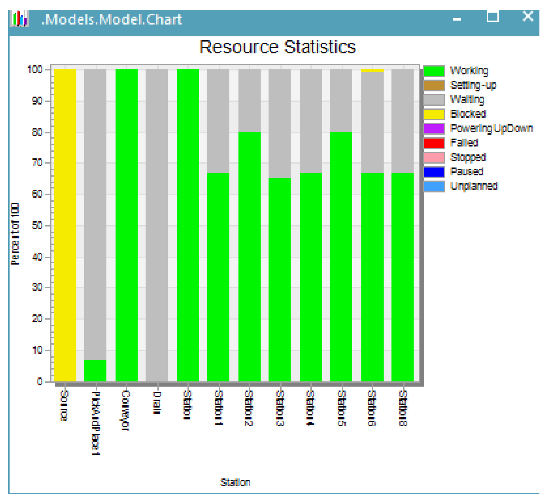
Follow the trail of blocked (yellow) stations to the station that is working 100% (green) and is followed by a station that is waiting (gray). Figure 7 shows the performance graphs of the individual workstations in the analyzed production process.
Statistical analysis of each workstation performed for the entire production process showed that only an average of 25% of production capacities are used. This is a phenomenon that adversely affects the dynamic operation of the system. It means that the stations are underloaded, only one being fully loaded. It is necessary to balance the production line.
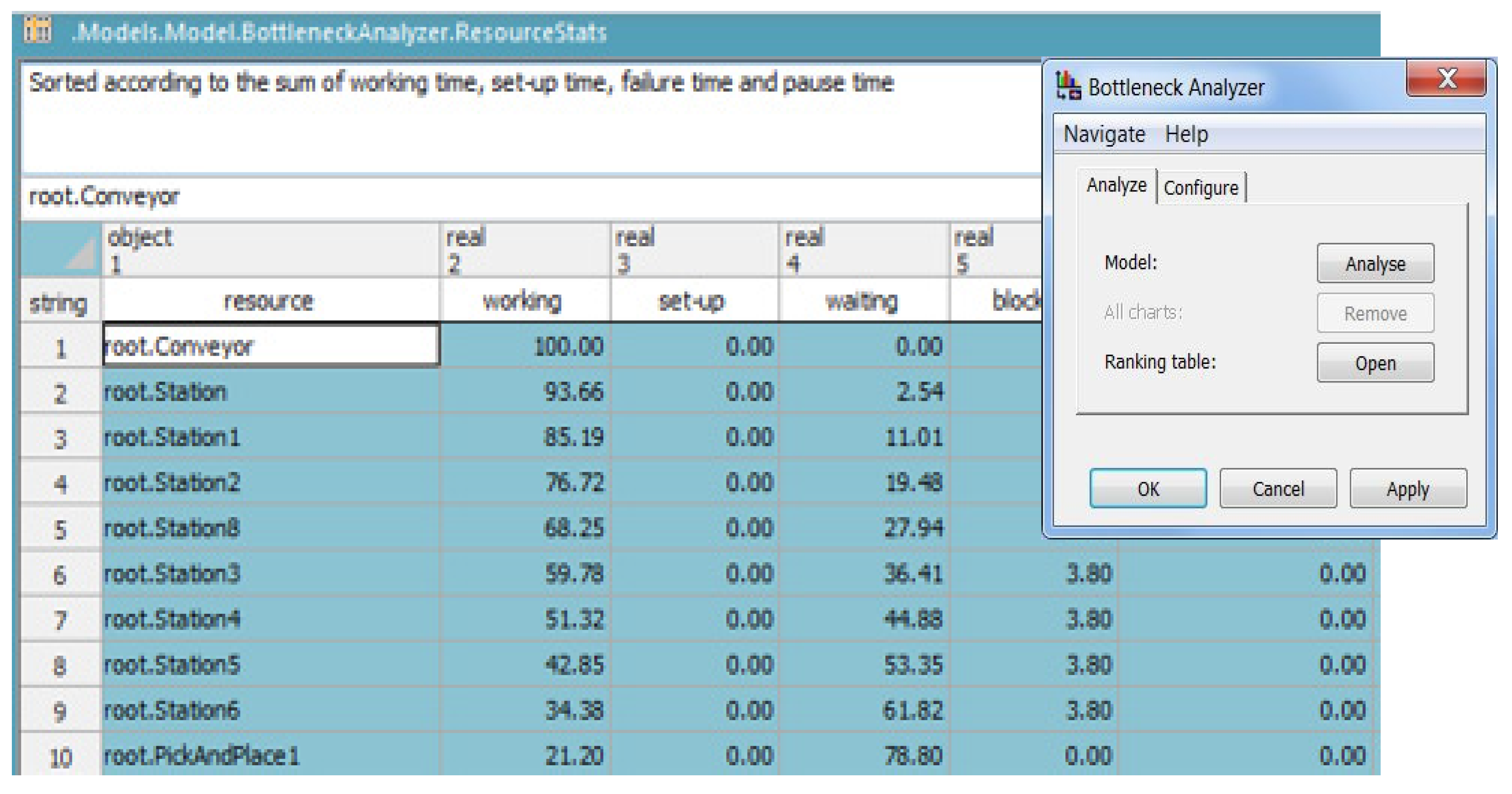
The values, the percentages of these bottlenecks in the total production time, and the loading degrees of the workstations are presented in Figure 8. All material flow objects and all moving objects enter their statistics values into the Resource Statistics Table, the Product Statistics Table, or the Complete Statistics Table.
After running the simulation, there is a relatively large dispersion of the loading degrees of the workstations in the system (21.20–100%), a feature of a flexible manufacturing system. It expresses the level at which production capacities are used. For ideal operation, it is 95–100%; the rest are auxiliary times. The lower the load levels, the higher the asynchronisms in the system and interruptions in operation. Management measures are required to reduce wait times in the system.
By running simulations considering another scenario of real-time operation, improvements can be achieved. This solution has produced favorable effects in terms of balancing the production line, trying to equalize the load of workstations and ensuring a continuous flow of production (Figure 9). At this stage, in order to simplify the process, neither the input sources of the parts in the system (Source) nor the output sources of the system (Drain) were taken into account.
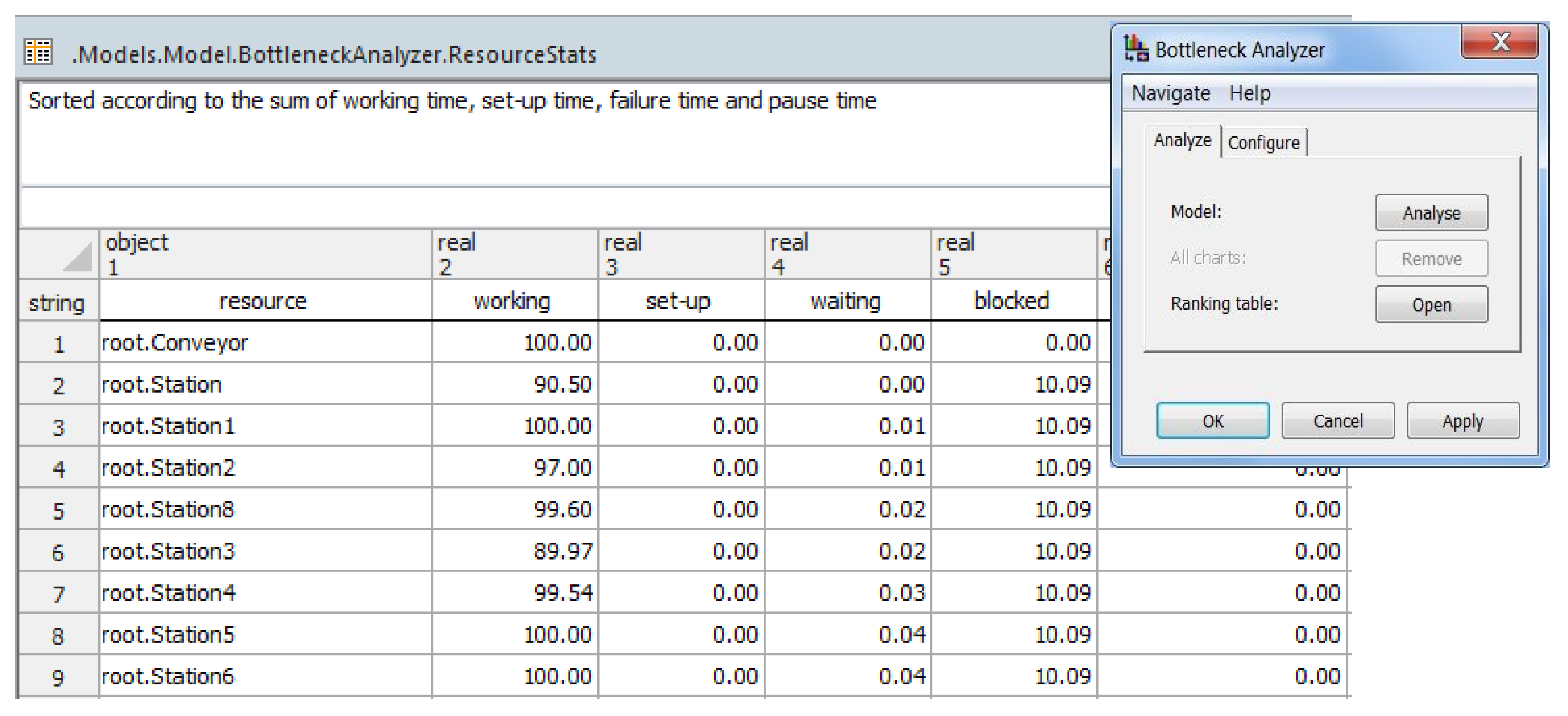
Figure 9 shows statistics for improving workstation activity by optimizing production time and by reducing wait times in the production process. Plant Simulation opens a table that contains all values it collected during a simulation run (Figure 10). The statistics tab displays a snapshot in time. Each time that you view this tab, while a simulation is running, the statistics change.
Figure 10 shows statistics obtained from optimization by increasing the working times on each workstation and by reducing the wait times in the production process. It can be seen that all of the workstations in the system work at maximum capacity (90–100%). By running the simulation and by balancing the system using several scenarios, visible improvements were obtained in terms of blockage rate and workstation loading. The presented simulation program also performs animation features of movements carried out into the flexible manufacturing line. All material flow objects and all moving objects enter their statistics values into the Resource Statistics Table, the Product Statistics Table, or the Complete Statistics Table (Siemens AG 2015, Siemens Product Lifecycle Management Software Inc., Germany [44]).
Tests that can be performed by computer simulations lead to solutions to optimize the operation of FMS and thus to eliminate bottlenecks. Among the solutions for solving and eliminating a bottleneck, the following can be mentioned: increasing the number of overtime hours, working in several shifts, arranging workstations in parallel, implementing quality control methods, implementing automations, and using modern management methods such as Lean Production, issues that will be addressed in future research projects.
In many companies, there is a lack of a support framework between engineers and process information. The creation of this framework could contribute to the elimination of waste, wait times in attempts to balance production lines, and reconfiguration of the system.
4. Conclusions
The mathematical model of system coupling expresses the operating program of the entire system. The matrix method for modeling flexible manufacturing systems is easy to use for computer simulation of the system operation. This mathematical model of system coupling is at the base of the development of the FMS simulation algorithm for processing cylindrical parts, such as bearing rings.
The resulting matrices provide an overview of the entire manufacturing system, allowing rapid error detection and prompt corrective action. It was thus possible to study the complex interactions within the flexible manufacturing system analyzed, which contributed to increasing the performance of the system. The model allowed for knowing the number of processing subsystems, their appearance, and their diversity. Through the designed graphic-analytical model, the interactions between the subsystems, system inputs, and the outputs were defined and analyzed. The configuration of the system structure of the processing systems and the logistics subsystem had a direct influence on the production capacity and adaptability by reconfiguration. In the simulation phase, the evaluation of the performance criteria allowed the introduction of system resource planning strategies.
By implementing the developed mathematical models, the major problems of flexible manufacturing systems were solved:
- -
- adequate representation of the large system (with customization for FMS design for processing parts of the revolution), development of the system architecture, and its configuration: sizing, configuration, and reconfiguration
- -
- dynamic modeling of the behavior of large systems and therefore of FMS (Flexible Manufacturing System) and finding the appropriate mathematical formulae for model representation: the static and the dynamical simulations
- -
- study of the evolution and the spatial and temporal behavior of flexible manufacturing systems: dynamic simulation.
- -
- decomposition of the system into subsystems and coordination of them by establishing interactions and causal links, resulting in the designed analytical model being implemented in the management of flexible manufacturing systems, as a future direction of research
The verification and validation of the model were confirmed by using existing software and modern equipment in the modeling and simulation laboratory of production systems and in the research center. The developed research has generated useful results with an impact on the industrial reality, narrowing the gap between theory and practice and opening other research directions, having as a cumulative effect the reduction of the degree of indeterminacy that exists in the field of flexible manufacturing.
Based on the mathematical and graphic-analytical models of sizing, configuration, optimization, and original simulation, a modularized system for simulating the manufacture of bearing rings was designed and developed. The original software package for simulation applications in the design of flexible manufacturing systems came from the need to describe and study the behavior of a real system in order to control and manage the system in the future. Aspects concerning programming of flexible manufacturing systems with the aid of virtual reality will be developed.
Following validation of the system operation, utility in the design and management of the processes in the environment and real time resulted regarding the influence of the changes in the structure of the system on its behavior, the influence of the evolutions of the commands and the states of the system on its outputs, and the influence of the initial conditions or of some parameters on the FMS behavior. Thus, one can explore without interruption the ongoing operations, new operating procedures, decision rules, information flows, material flows, etc. for the system analyzed by simulation.
Future research will be more focused not only on the practical use of these methodologies but also on the development of new methods for analysis of the efficiency of the technological transfer in the context of the new world of IT and automation. The research will go beyond the field of FMSs management and control in real environment. The implementation of an FMS in an integrate manufacturing system represents an important result, which leads to optimization of the entire material and information flux of the enterprise. Moreover, by this study, we identified the possibilities of consolidating research and of applying it in industry on the purpose of issuing possible further contracts.
Author Contributions
Conceptualization, A.F. and S.A.B.; methodology, A.F.; software, A.F. and S.A.B.; validation, A.F. and S.A.B.; formal analysis, S.A.B.; investigation, A.F. and S.A.B.; resources, S.A.B. and A.F.; data curation, A.F. and S.A.B.; writing—original draft preparation, A.F. and S.A.B.; writing—review and editing, A.F.; visualization, S.A.B.; supervision, A.F.; project administration, A.F. and S.A.B.; funding acquisition, A.F. and S.A.B. All authors have read and agreed to the published version of the manuscript.
Funding
This research has been supported by funding from Transilvania University of Brasov, Romania.
Conflicts of Interest
The authors declare no conflict of interest.
References
- Moeuf, A.; Pellerin, R.; Lamouri, S.; Tamayo-Giraldo, S.; Barbaray, R. The industrial management of SMEs in the era of Industry 4.0. Int. J. Prod. Res. 2018, 56, 1118–1136. [Google Scholar] [CrossRef] [Green Version]
- Schallmo, D.; Williams, C.A.; Boardman, L. Digital Transformation of Business Models—Best Practice, Enablers, and Roadmap. Int. J. Innov. Manag. 2017, 21, 1740014. [Google Scholar] [CrossRef] [Green Version]
- Li, H.; Wu, Y.; Cao, D.; Wang, Y. Organizational mindfulness towards digital transformation as a prerequisite of information processing capability to achieve market agility. J. Bus. Res. 2020; in press. [Google Scholar]
- Planing, P. Will digital boost circular? Evaluating the impact of the digital transformation on the shift towards a circular economy. Int. J. Manag. Cases 2017, 19, 22–31. [Google Scholar]
- Kaltum, U.; Widodo, A.; Widiasmono, A. Local TV Goes to Global Market through Digital Transformation. Acad. Strateg. Manag. J. 2016, 15, 221–229. [Google Scholar]
- Bican, P.M.; Brem, A. Digital Business Model, Digital Transformation, Digital Entrepreneurship: Is There A Sustainable “Digital”? Sustainability 2020, 12, 5239. [Google Scholar] [CrossRef]
- Holmström, J.; Liotta, G.; Chaudhuri, A. Sustainability outcomes through direct digital manufacturing-based operational practices: A design theory approach. J. Clean. Prod. 2017, 167, 951–961. [Google Scholar] [CrossRef]
- Gania, I.P.; Stachowiak, A.; Oleśków-Szłapka, J. Flexible manufacturing systems: Industry 4.0 solution. In Proceedings of the 24th International Conference on Production Research (ICPR), Posnan, Poland, 30 July–3 August 2017; ISBN 978-1-60595-507-0. [Google Scholar]
- Yin, Y.; Stecke, K.E.; Li, D. The evolution of production systems from Industry 2.0 through Industry 4.0. Int. J. Prod. Res. 2018, 56, 848–861. [Google Scholar] [CrossRef] [Green Version]
- Pilloni, V. How Data Will Transform Industrial Processes: Crowdsourcing and Big Data as Pillars of Industry 4.0. Future Internet 2018, 10, 24. [Google Scholar] [CrossRef] [Green Version]
- Yang, R.C.; Takeda, Y.; Zhang, C.; Fang, G. Robotics and Mechatronics: Proceedings of the Fifth IFToMM International Symposium on Robotics & Mechatronics (ISRM); Springer: Berlin/Heidelberg, Germany, 2017. [Google Scholar]
- Culot, G.; Nassimbeni, G.; Orzes, G.; Sartor, M. Behind the definition of Industry 4.0. Analysis and open questions. Int. J. Prod. Econ. 2020, 226, 107617. [Google Scholar] [CrossRef]
- Arnold, C.; Kiel, D.; Voigt, K.I. How the Industrial Internet of Things Changes Business Models in Different Manufacturing Industries. Int. J. Innov. Manag. 2016, 20, 1640015. [Google Scholar] [CrossRef]
- Qin, J.; Liua, Y.; Grosvenor, R. A Categorical Framework of Manufacturing for Industry 4.0 and Beyond. Procedia CIRP 2016, 52, 173–178. [Google Scholar] [CrossRef] [Green Version]
- Tran, L.V.; Huynh, B.H.; Akhtar, H. Ant Colony Optimization Algorithm for Maintenance, Repair and Overhaul Scheduling Optimization in the Context of Industry 4.0. Appl. Sci. 2019, 9, 4815. [Google Scholar] [CrossRef] [Green Version]
- Santos, K.; Loures, E.; Piechnicki, F.; Canciglieri, O. Opportunities Assessment of Product Development Process in Industry 4.0. Procedia Manuf. 2017, 11, 1358–1365. [Google Scholar] [CrossRef]
- Müller, J.M.; Kiel, D.; Voigt, K.I. What Drives the Implementation of Industry 4.0? The Role of Opportunities and Challenges in the Context of Sustainability. Sustainability 2018, 10, 247. [Google Scholar] [CrossRef] [Green Version]
- Motyl, B.; Baronio, G.; Uberti, S.; Speranza, D.; Filippi, S. How will change the future engineers’ skills in the industry 4.0 framework? A questionnaire survey. Procedia Manuf. 2019, 11, 1501–1509. [Google Scholar] [CrossRef]
- Liu, P.; Zhang, Q.; Pannek, J. Development of Operator Theory in the Capacity Adjustment of Job Shop Manufacturing Systems. Appl. Sci. 2019, 9, 2249. [Google Scholar] [CrossRef] [Green Version]
- Groover, M.P. Automation, Production Systems, ad Computer-Integrated Manufacturing, 4th ed.; Pearson Higher Eduation, Inc.: London, UK, 2015. [Google Scholar]
- Fragapane, G.; Ivanov, D.; Peron, M.; Sgarbossa, F.; Strandhagen, J.O. Increasing flexibility and productivity in Industry 4.0 production networks with autonomous mobile robots and smart intralogistics. Ann. Ope. Res. 2020. [Google Scholar] [CrossRef] [Green Version]
- Diaz, J.L.; Ocampo-Martinez, C.; Olaru, S. Dual mode control strategy for the energy efficiency of complex and flexible manufacturing systems. J. Manuf. Syst. 2020, 56, 104–116. [Google Scholar] [CrossRef]
- Seebacher, G.; Herwig, W. Evaluating flexibility in discrete manufacturing based on performance and efficiency. Int. J. Prod. Econ. 2014, 153, 340–351. [Google Scholar] [CrossRef]
- Lezzi, M.; Lazoi, M.; Corallo, A. Cybersecurity for Industry 4.0 in the current literature: A reference framework. Comput. Ind. 2018, 103, 97–110. [Google Scholar] [CrossRef]
- Tempelmeier, H.; Kuhn, H. Flexible Manufacturing Systems: Decision Support for Design and Operation; Wiley Series in Systems Engineering; Wiley: New York, NY, USA, 1993. [Google Scholar]
- Canetta, L.; Barni, A.; Montini, E. Development of a digitalization maturity model for the manufacturing sector. In Proceedings of the 2018 IEEE International Conference on Engineering, Technology and Innovation, Stuttgart, Germany, 17–20 June 2018. [Google Scholar]
- Parida, V.; Sjödin, D.; Reim, W. Reviewing literature on digitalization, business model innovation, and sustainable industry: Past achievements and future promises. Sustainability 2019, 11, 391. [Google Scholar] [CrossRef] [Green Version]
- Sahu, A.; Pradhan, S.K. Quantitative analysis and optimization of production line based on multiple evaluation criteria using discrete event simulation: A review. In Proceedings of the International Conference on Automatic Control and Dynamic Optimization Techniques (ICACDOT), Pune, India, 9–10 September 2016; pp. 612–617. [Google Scholar]
- Karnon, J.; Stahl, J.; Brennan, A.; Caro, J.J.; Mar, J.; Möller, J. Modeling using discrete event simulation: A report of the ISPOR-SMDM Modeling Good Research Practices Task Force—4. Value Health 2012, 15, 821–827. [Google Scholar] [CrossRef] [PubMed] [Green Version]
- Yadav, A.; Jayswal, S.C. Modelling of flexible manufacturing system: A review. Int. J. Prod. Res. 2018, 56, 2464–2487. [Google Scholar] [CrossRef]
- Kusiak, A. Smart manufacturing. Int. J. Prod. Res. 2018, 56, 508–517. [Google Scholar] [CrossRef]
- Smuts, S.; van der Merwe, A.; Smuts, H.A. Strategic Organizational Perspective of Industry 4.0: A Conceptual Model. In I3E 2020: Implementation and Use of Information and Communication Technology; Lecture Notes in Computer Science; Springer: Cham, Switzerland, 2020; Volume 12066. [Google Scholar]
- Reddy, B.S.P.; Rao, C.S.P. FMS modelling and performance evaluation using Autmod. Int. J. Sim. Model. 2011, 10, 78–90. [Google Scholar] [CrossRef]
- Song, B.; Hutabarat, W.; Tiwari, A.; Enticott, S. Integrating Optimisation with Simulation for Flexible Manufacturing System; Advances in Transdisciplinary Engineering; IOS Press: Amsterdam, The Netherlands, 2016. [Google Scholar] [CrossRef]
- Dubey, R.; Ali, S.S. Identification of flexible manufacturing system dimensions and their interrelationship using total interpretive structural modelling and fuzzy MICMAC analysis. Glob. J. Flex. Syst. Manag. 2014, 15, 131–143. [Google Scholar] [CrossRef]
- Ottogalli, K.; Rosquete, D.; Amundarain, A.; Aguinaga, I.; Borro, D. Flexible Framework to Model Industry 4.0 Processes for Virtual Simulators. Appl. Sci. 2019, 9, 4983. [Google Scholar] [CrossRef] [Green Version]
- Souravlas, S.; Katsavounis, S.; Anastasiadou, S. On Modeling and Simulation of Resource Allocation Policies in Cloud Computing Using Colored Petri Nets. Appl. Sci. 2020, 10, 5644. [Google Scholar] [CrossRef]
- Toader, F.A. Production scheduling in flexible manufacturing systems: A state of the art survey. J. Electr. Eng. Electron. Control Comput. Sci. 2017, 3, 1–6. [Google Scholar]
- Qin, W.; Zhang, J.; Song, D. An improved ant colony algorithm for dynamic hybrid flow shop scheduling with uncertain processing time. J. Intell. Manuf. 2018, 29, 891–904. [Google Scholar] [CrossRef]
- Jus, M. Modeling with Tecnomatix Plant Simulation. Univ. Rev. 2017, 11, 12–15. [Google Scholar]
- Blaga, F.; Stanăşel, I.; Hule, V.; Pop, A. Balancing the manufacturing lines through modelling and simulation using Tecnomatix Plant Simulation. In Proceedings of the 21st Innovative Manufacturing Engineering & Energy International Conference, Iasi, Romania, 24–27 May 2017; Volume 112, p. 06012. [Google Scholar] [CrossRef] [Green Version]
- Lidberg, S.; Aslam, T.; Pehrsson, L.; Ng, A.H. Optimizing real‑world factory fows using aggregated discrete event simulation modelling. Flex. Serv. Manuf. J. 2019. [Google Scholar] [CrossRef] [Green Version]
- Kikolski, M. Identification of production bottlenecks with the use of Plant Simulation software. Econ. Manag. 2016, 8. [Google Scholar] [CrossRef] [Green Version]
- Siemens, A.G. Plant Simulation Basics, Methods, and Strategies, Student Guide, MT46101—Version 12; Siemens Product Lifecycle Management Software Inc.: Plano, TX, USA, 2015. [Google Scholar]
- Tecnomatix Plant Simulation Step-by-Step Help; Siemens Product Lifecycle Management Software Inc., 2011; Available online: https://docs.plm.automation.siemens.com/content/plant_sim_help/15/plant_sim_all_in_one_html/en_US/tecnomatix_plant_simulation_help/step_by_step_help/step_by_step_help.html (accessed on 7 July 2020).
- Smith, J.S. Survey on the use of simulation for manufacturing system design and operation. J. Manuf. Syst. 2013, 22, 157–171. [Google Scholar] [CrossRef]
- Khaleel, A. Modeling and Optimization in a new Machining Production Line by using Manufacturing System Simulation. In Proceedings of the International Conference on Industrial Engineering and Operations Management, Detroit, MI, USA, 23–25 September 2016. [Google Scholar]
- Kikolsk, M. Study of Production Scenarios with the Use of Simulation Models, 7th International Conference on Engineering, Project, and Production Management. Procedia Eng. 2017, 182, 321–328. [Google Scholar] [CrossRef]
- Fota, A. Flexible Manufacturing Systems Design. Modeling and Simulation; Transilvania University of Brasov Publishing House: Brașov, Romania, 2004. (In Romanian) [Google Scholar]
- Chan, F. A comprehensive survey and future trend of simulation study on FMS. J. Intell. Manuf. 2004, 15, 87–102. [Google Scholar] [CrossRef]
- Wu, C.; Fan, Y.S.; Xiao, D.Y. Computer Integrated Manufacturing. In Handbook of Industrial Engineering, 3rd ed.; John Wiley &Sons: Hoboken, NJ, USA, 2007. [Google Scholar]
- CIT Automations—Smart Electric Drives. Available online: https://actionarielectrice.ro/roboti-industriali-yamaha/ (accessed on 7 July 2020). (In Romanian).
- Florescu, A.; Barabas, S. Decision models in designing flexible production systems. In Proceedings of the 4th International Conference on Computing and Solutions in Manufacturing Engineering, Rome, Italy, 3–5 January 2017; Volume 94, p. 79406007. [Google Scholar]
- Krauszová, A. Use of plant simulation in area of storage. Acta Simul. Int. Sci. J. Simul. 2015, 1, 1–5. [Google Scholar]
- Kelton, W.D.; Sadowski, R.P.; Swets, N.B. Simulation with ARENA, 5th ed.; McGraw-Hill: New York, NY, USA, 2010. [Google Scholar]
Figure 1.
Graphic model of the system.

Figure 2.
Integrated automated manufacturing system (Source: CIT Automatizari—Actionari electrice inteligente (in Romanian) [52]).
Figure 2.
Integrated automated manufacturing system (Source: CIT Automatizari—Actionari electrice inteligente (in Romanian) [52]).

Figure 3.
The decomposable structural diagram of the designed system.

Figure 4.
The sequence from the simulation in Tecnomatix of the designed system.

Figure 5.
Simulation model 2D: A intermediate sequence.

Figure 6.
Identification of production bottlenecks.

Figure 7.
Statistics concerning the work of machines in the current production process.

Figure 8.
Bottleneck Analyzer: the percentage of workstation usage.

Figure 9.
Statistics concerning the work of machines in the production process. after optimization.

Figure 10.
Bottleneck Analyzer after optimization.


Table 1.
Flow symbols.
| Flow Type | Symbol |
|---|---|
| Information flow (IF) |  |
| Energy flow (EF) |  |
| Semi-finished product flow (SF) |  |
| Finished parts/flow parts (FF) |  |
Table 2.
Symbols for subsystems and flows.
| Subsystem Type | Symbol |
|---|---|
| Input subsystem (Si) |  |
| Output subsystem (So) |  |
Publisher’s Note: MDPI stays neutral with regard to jurisdictional claims in published maps and institutional affiliations. |
© 2020 by the authors. Licensee MDPI, Basel, Switzerland. This article is an open access article distributed under the terms and conditions of the Creative Commons Attribution (CC BY) license (http://creativecommons.org/licenses/by/4.0/).
Share and Cite
MDPI and ACS Style
Florescu, A.; Barabas, S.A. Modeling and Simulation of a Flexible Manufacturing System—A Basic Component of Industry 4.0. Appl. Sci. 2020, 10, 8300. https://0-doi-org.brum.beds.ac.uk/10.3390/app10228300
AMA Style
Florescu A, Barabas SA. Modeling and Simulation of a Flexible Manufacturing System—A Basic Component of Industry 4.0. Applied Sciences. 2020; 10(22):8300. https://0-doi-org.brum.beds.ac.uk/10.3390/app10228300
Chicago/Turabian StyleFlorescu, Adriana, and Sorin Adrian Barabas. 2020. "Modeling and Simulation of a Flexible Manufacturing System—A Basic Component of Industry 4.0" Applied Sciences 10, no. 22: 8300. https://0-doi-org.brum.beds.ac.uk/10.3390/app10228300
Note that from the first issue of 2016, this journal uses article numbers instead of page numbers. See further details here.