Effect of Rejuvenation Heat Treatment on the Creep Property and Microstructural Evolution of a Ni-Base Superalloy

1
School of Mechanical Engineering, Tianjin University of Technology and Education, Tianjin 300222, China
2
College of Aeronautical Engineering, Civil Aviation University of China, Tianjin 300300, China
3
Institute of Metal Research, Chinese Academy of Sciences, Shenyang 110016, China
*
Author to whom correspondence should be addressed.
Appl. Sci. 2020, 10(3), 1187; https://0-doi-org.brum.beds.ac.uk/10.3390/app10031187
Submission received: 13 January 2020
/
Revised: 31 January 2020
/
Accepted: 3 February 2020
/
Published: 10 February 2020
(This article belongs to the Special Issue Microstructural and Mechanical Properties of Metallic Materials)
Abstract
:Interrupted creep tests were performed on a polycrystalline Ni-base superalloy, and rejuvenation heat treatment (RHT) was carried out to restore the creep resistance. During creep deformation, the microstructural evolution can be characterized as coarsening and rafting of γ′ precipitates, formation of dislocation networks in matrix channels, γ′ shearing by dislocations and carbides transformation from MC to M6C type. In the sample with low precrept strain, the dislocation networks can be effectively removed after RHT and the size and morphology of γ′ particles were similar to that just after heat treatment. However, the microstructure in the sample with higher creep strain after RHT cannot be fully restored to the original state in terms of dislocations and distribution of γ′ particles. The subsequent creep results exhibit that creep property is also relevant to the precrept strain, which exhibits a good agreement with microstructure observations. In addition, RHT cannot reverse the carbide transformation from MC to M6C type but enhances this process, which can be evident by the change of the area fraction of these two types of carbides. The effect of carbides transformation on the creep resistance of K465 alloy is not pronounced.
1. Introduction
Microstructure characteristics play the most important role in determining the mechanical properties of materials at room temperature and elevated temperatures. Many works have been dedicated to the modification of microstructures and improvement of mechanical properties in the past decade [1,2,3,4]. In the case of materials used at elevated temperatures, Ni-base superalloy is widely utilized in crucial components such as blades and vanes in gas turbine engines due to its superior high-temperature properties [5]. These components are usually operated in severe circumstances combining elevated temperatures and complicated stress states, which induces significant microstructural degradation and leads to the failure of these components. To evaluate the high-temperature properties of Ni-base superalloy, the creep rupture test is primarily considered since these components are subjected to high centrifugal forces during operation [6,7,8].
The excellent high-temperature strength of nickel-based superalloy is predominantly derived from the solid-solution strengthening of refractory chemical elements, homogeneous distribution of ordered γ′ precipitates embedded in the γ matrix and precipitation of carbides [9,10]. Under the high stress loads at elevated temperatures, the microstructure of the superalloy undergoes significant changes, such as transformation of carbides [11,12,13], coarsening or rafting of γ′ precipitates [14], formation of dislocation networks and shearing of γ′ precipitates by dislocation pairs [15,16,17], which lead to the ultimate failure of these components. Therefore, these components must be replaced when the microstructural degeneration has been accumulated to a certain extent, which is quite costly. On the other hand, rejuvenation heat treatment (RHT) provides a way to reduce the cost of this replacement [18,19,20,21,22,23,24]. If a degraded microstructure as well as the high-temperature property of a Ni-base superalloy can be restored to its pre-service condition by performing a specific RHT, the service life of these components can be substantially extended.
To verify the effectiveness of RHT, one has to consider the microstructure evolutions during creep and RHT. Therefore, the rafted γ′ precipitates, decomposition of carbides and change of dislocation configuration must be compared at different stages. In the present study, a polycrystalline cast Ni-base superalloy K465 was used in a creep test. After heat treatment, finely distributed γ′ precipitates and a large amount of carbides are formed in the matrix. RHT was carried out on the crept samples with different levels of accumulated strain. The samples were tested again to evaluate the effectiveness of RHT. At each state, the microstructure in the dendrite core (DC) and in the interdendritic region were investigated respectively. The effect of RHT on microstructure rejuvenation was discussed based on the morphology of γ′ precipitates, area fraction of carbides and dislocation configuration.
2. Materials and Methods
The material investigated in the present study is a cast polycrystalline superalloy K465, and the nominal chemical composition (wt %) of K465 alloy is shown in Table 1. After vacuum induction melting (VIM) and casting, alloy bars received a conventional solution treatment at 1210 °C for 4 h. The temperature for heat treatment was controlled within ±1 °C. These alloy bars were then machined into cylindrical specimens with the gauge length of 25 mm and diameter of 5 mm. In the present study, all creep tests were conducted at 975 °C with applied stress of 225 MPa by following the International Organization for Standardization (ISO) standard [25]. This accelerated creep condition was chosen to reduce the change of specimen geometry induced by oxidation. Before precrept test and RHT, four specimens with the same casting conditions were creep-tested to fracture. The average creep life of this alloy is 110 ± 10 h. A number of specimens were creep-tested with an accumulated strain of 0.03, 0.05, and 0.07 respectively. After that, the specimens underwent rejuvenation treatment in a furnace with vacuum circumstance. The RHT was carried out at 1220 °C for 6 h in order to restore the microstructure, and then the specimens were creep-tested again. Before performing the creep test, the surfaces of all the samples were carefully polished to remove the thin oxidation layers formed during the accumulated test and RHT. The gauge length and diameter of cross section were then measured again to ensure that the applied stress was the same as the first creep test.
For microstructural examination, all samples were cut from the gauge section of crept samples and mechanically polished. After chemically etching in a solution mixture of 40 mL C2H5OH, 1.5 g CuSO4 and 20 mL deionized water, all samples were observed by a JSM-6301F field-emission scanning electron microscope (SEM) (JEOL, Tokyo, Japan). Back scattering electron (BSE) images and electron probe microanalysis (EPMA) (JEOL, Tokyo, Japan) were used to identify the types of carbides. To quantitatively evaluate the area fraction of carbides, we used an image analysis system, and at least 6 images were taken from one sample. Thin foils were also prepared for transmission electron microscope observation by using the twin-jet thinning method in 7 % perchloric acid ethanol solution at −20 °C, 15 V. All transmission electron microscope (TEM) micrographs were taken using a TECNAI 20 (FEI, Eindhoven, Netherlands) instrument operating at 200 kV.
3. Results and Discussion
3.1. Initial Microstructure and Creep Property of K465 Alloy
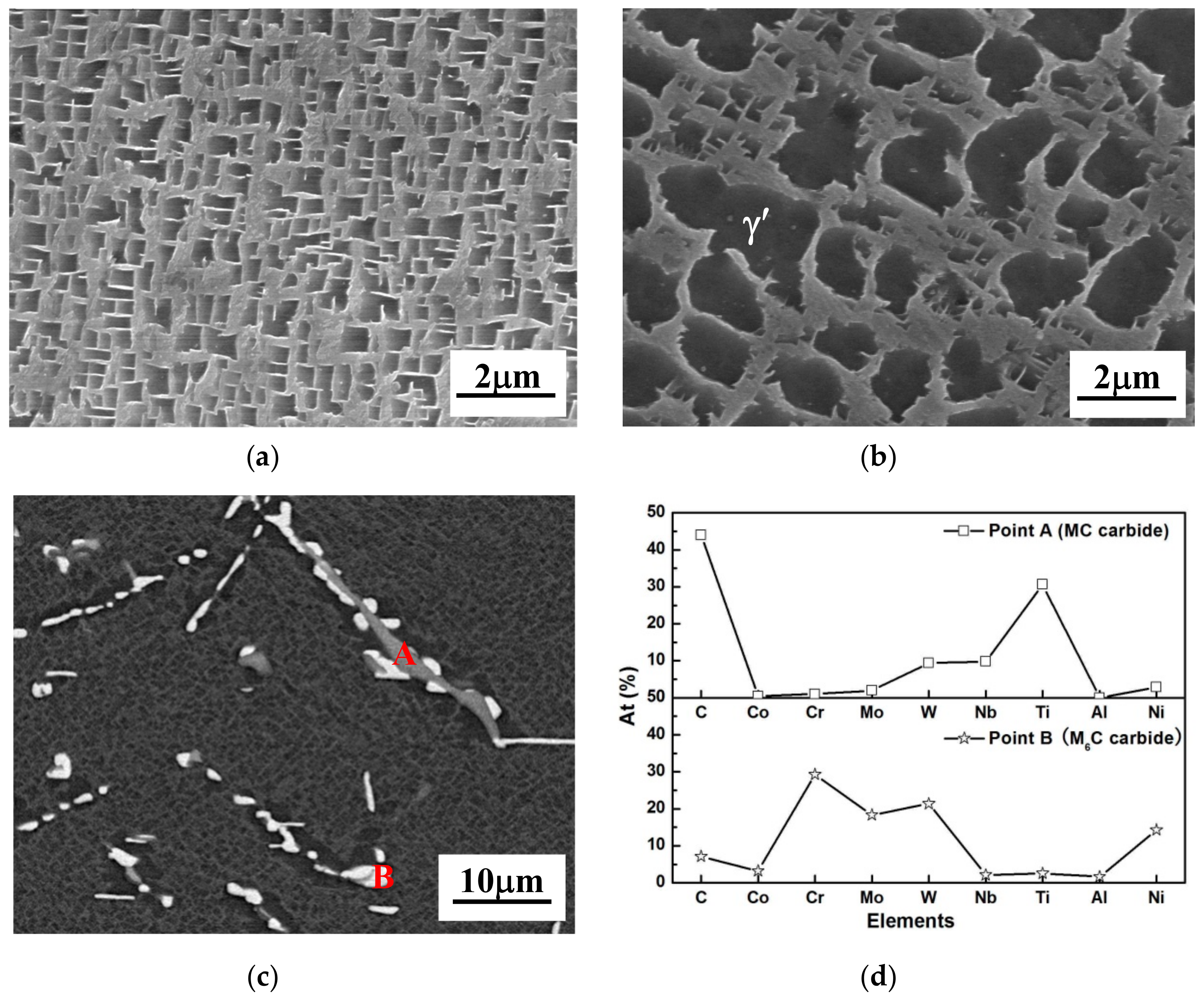
The grain size of as-cast K465 alloy is about 1.2 mm. After conventional heat treatment, the microstructure was observed by a SEM. From Figure 1a, it can be seen that the cuboidal γ′ particles in the dendritic core (DC) are homogeneously embedded in the γ matrix, the size of which ranges from 300 to 600 nm, which is evaluated by the linear intersection approach. However, the precipitation of γ′ in the interdendritic region (ID) is quite different from that in the DC, which is likely caused by chemical segregation during dendritic solidification, as can be seen in Figure 1b. Two types of γ′ particles formed in the ID, namely, large ones with an irregular shape and small ones with a size similar to those in the DC.
Apart from the precipitation of γ′, there is a large number of carbides which form in the ID after heat treatment. The BSE SEM image shown in Figure 1c reveals that these carbides have different contrast and can be classified into two types. Based on the Energy Dispersive X-ray spectroscopy (EDS) analysis, one can be identified as an MC-type carbide, which is rich in Ti, Nb, and W. The other is M6C, which is rich in Mo, W, and Cr. Both of these carbides contribute to the high temperature strength of K465 alloy during creep. Due to the variation in chemical composition, these carbides exhibit a different contrast in the BSE micrograph. To further confirm the type of carbides, the chemical composition of these carbides was analyzed by EPMA, the result of which is shown in Figure 1d. This observation indicates a good agreement with the carbides analysis reported in previous studies [26,27].
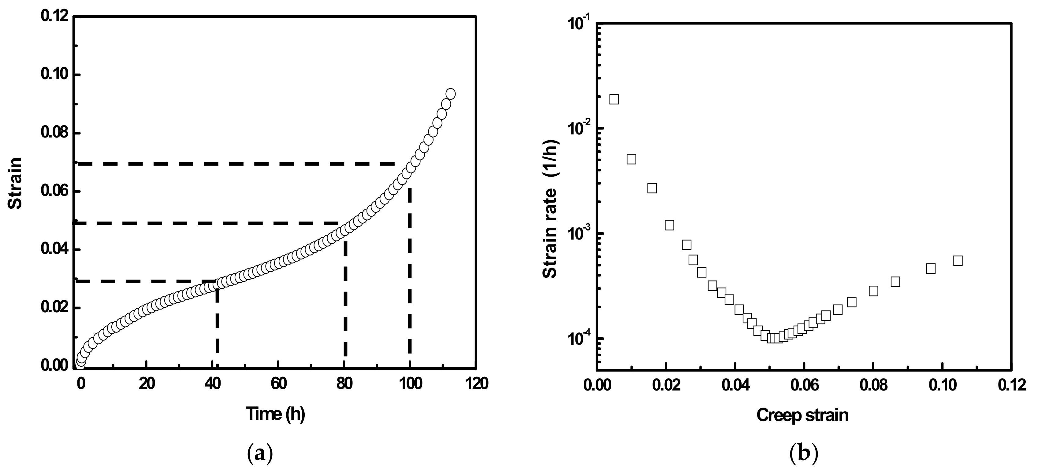
Figure 2a shows one typical creep curve of K465 alloy tested to fracture. The creep strain vs. strain rate curve of the same specimen is shown in Figure 2b. It can be seen that creep strain rate initially declines to a minimum value with the increase of creep strain and then gradually rises until a rupture occurs. On the basis of this curve, creep tests were interrupted with the creep strain reaching 0.03, 0.05, and 0.07 respectively, which roughly corresponds to the 40%, 60%, and 80% of total creep rupture time, and are indicated by the dashed lines in Figure 2a. These samples subsequently received RHT and were creep-tested again to evaluate the effectiveness of RHT.
3.2. Microstructure Examination of K465 Alloy after Interrupted Creep Test
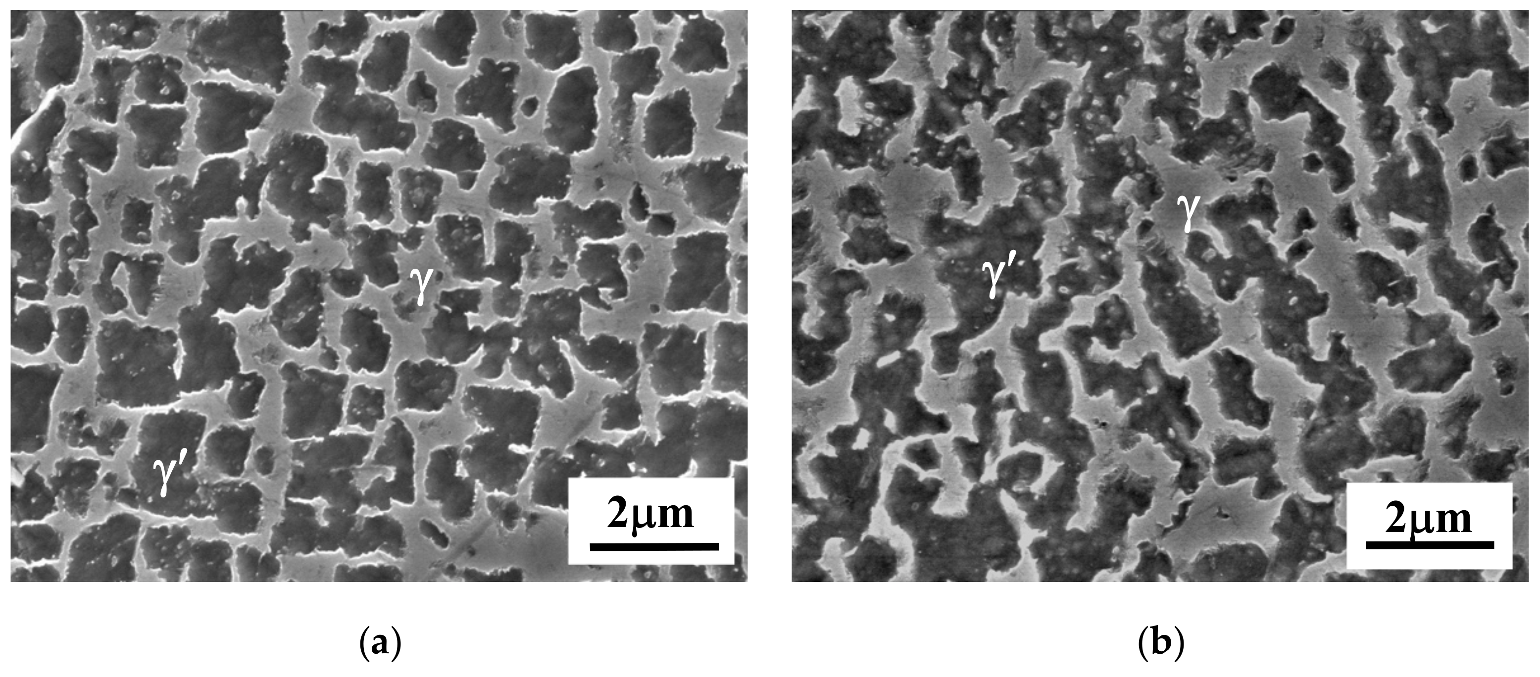
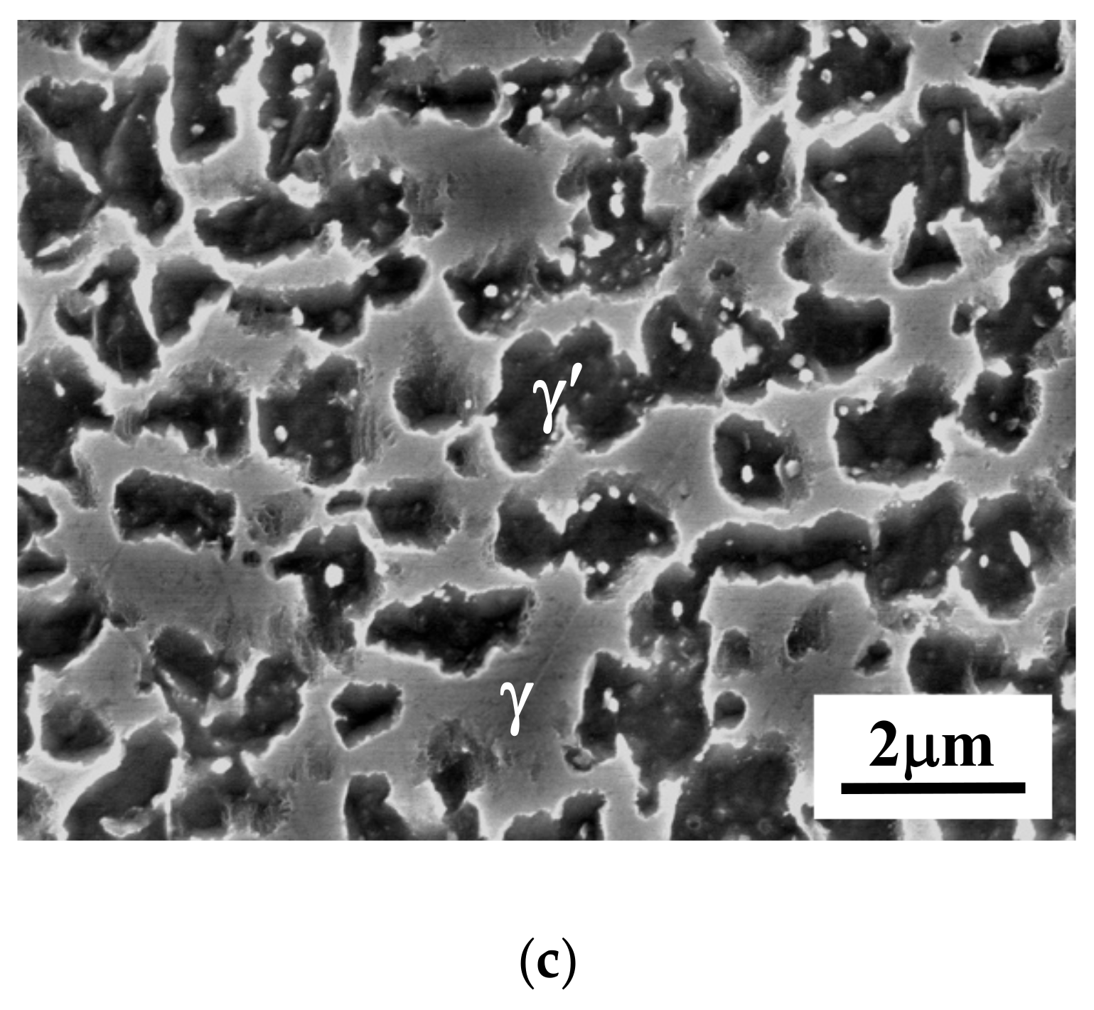
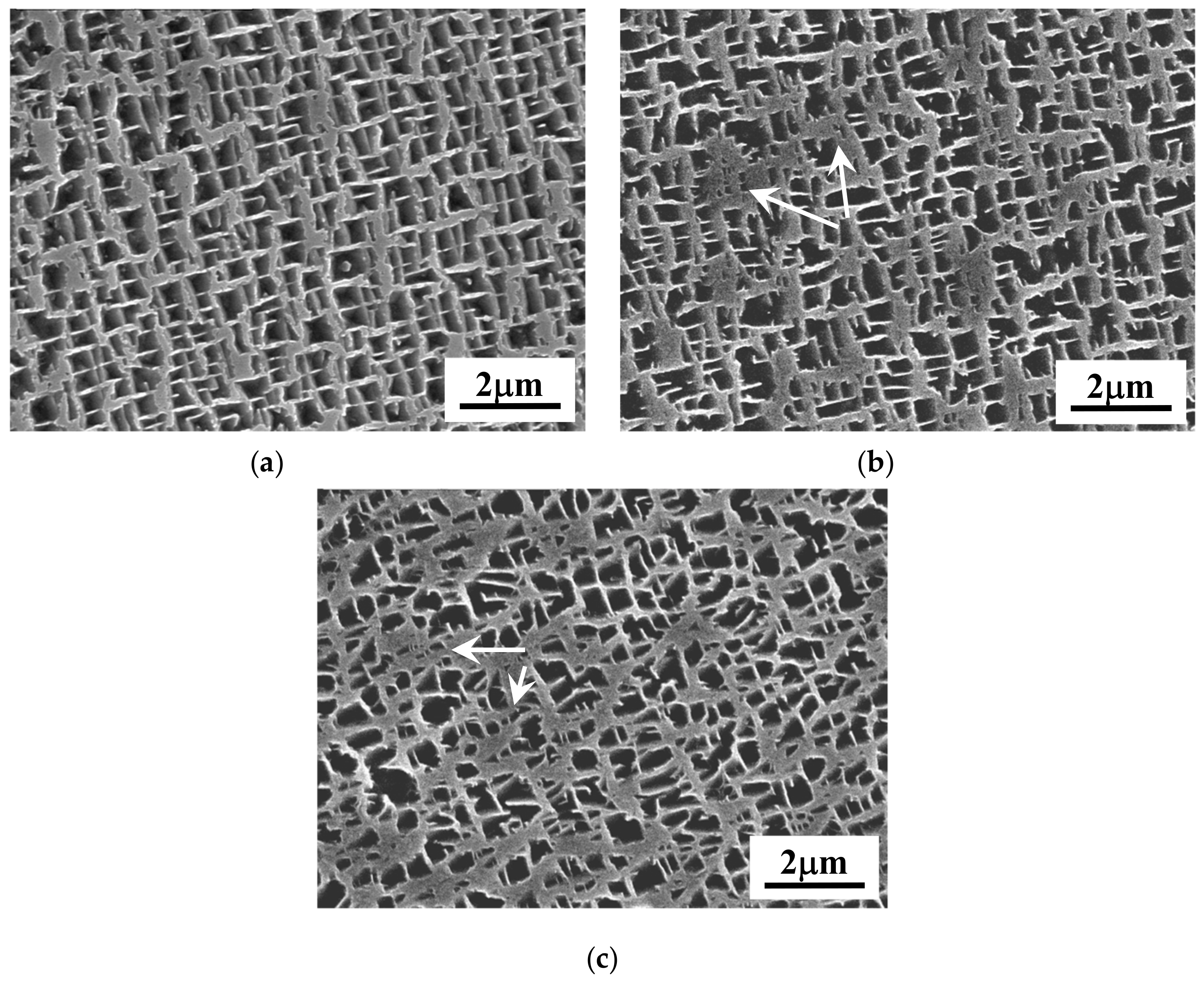
After interrupted creep, samples for microstructure examination were cut longitudinally from the gauge section of crept specimens. The SEM micrographs shown in Figure 3 demonstrate that the evolution of γ′ precipitates in the DC with different creep strains is quite pronounced. Some of the γ′ particles lost their cuboidal shape, and the coarsening of γ′ precipitate was obvious even in the sample with a relatively low creep strain of 0.03. The size of γ′ in this sample increased to 1 μm. With the increase of creep strain to 0.05, the morphology of all γ′ precipitates had become irregular, and they had coalesced with each other. Namely, the rafted γ′ microstructure was completely formed at this creep stage. In the sample with accumulated strain of 0.07, broadening of matrix channels was also apparent apart from the rafted microstructure. The analogous evolution of γ′ precipitates also occurred in the ID region. One typical microstructure in the interdendritic region after creep is shown in Figure 4. It can be seen that similar microstructural evolution also took place in the interdendritic region during creep, even though the original precipitation of γ′ was different in these two regions.
TEM micrographs in Figure 5 show the dislocation configuration of different samples. It can be seen that a large amount of dislocations were produced and the motion of these dislocations was confined by the γ/γ′ interfaces. As a consequence, dense dislocation networks were generated in the matrix channels even in the sample with creep strain of 0.03. This observation also demonstrated that creep deformation is mainly concentrated in the γ matrix, which is a softer phase compared to γ′ phase. The formation of these networks will change the γ/γ′ interfaces and retard the motion of dislocations in the matrix channels. This phenomenon was commonly observed in all of the samples, and it is the fundamental mechanism for creep deformation of Ni based superalloys [28,29]. In terms of dislocation networks, no apparent difference can be detected with respect to the creep strain. However, with the accumulation of creep strain, a larger number of dislocations were found to penetrate into γ′ precipitates, as indicated by the arrows in Figure 5c, which displays that these γ′ particles were sheared by dislocations in order to accommodate higher creep strain.
3.3. Microstructure Observation after RHT
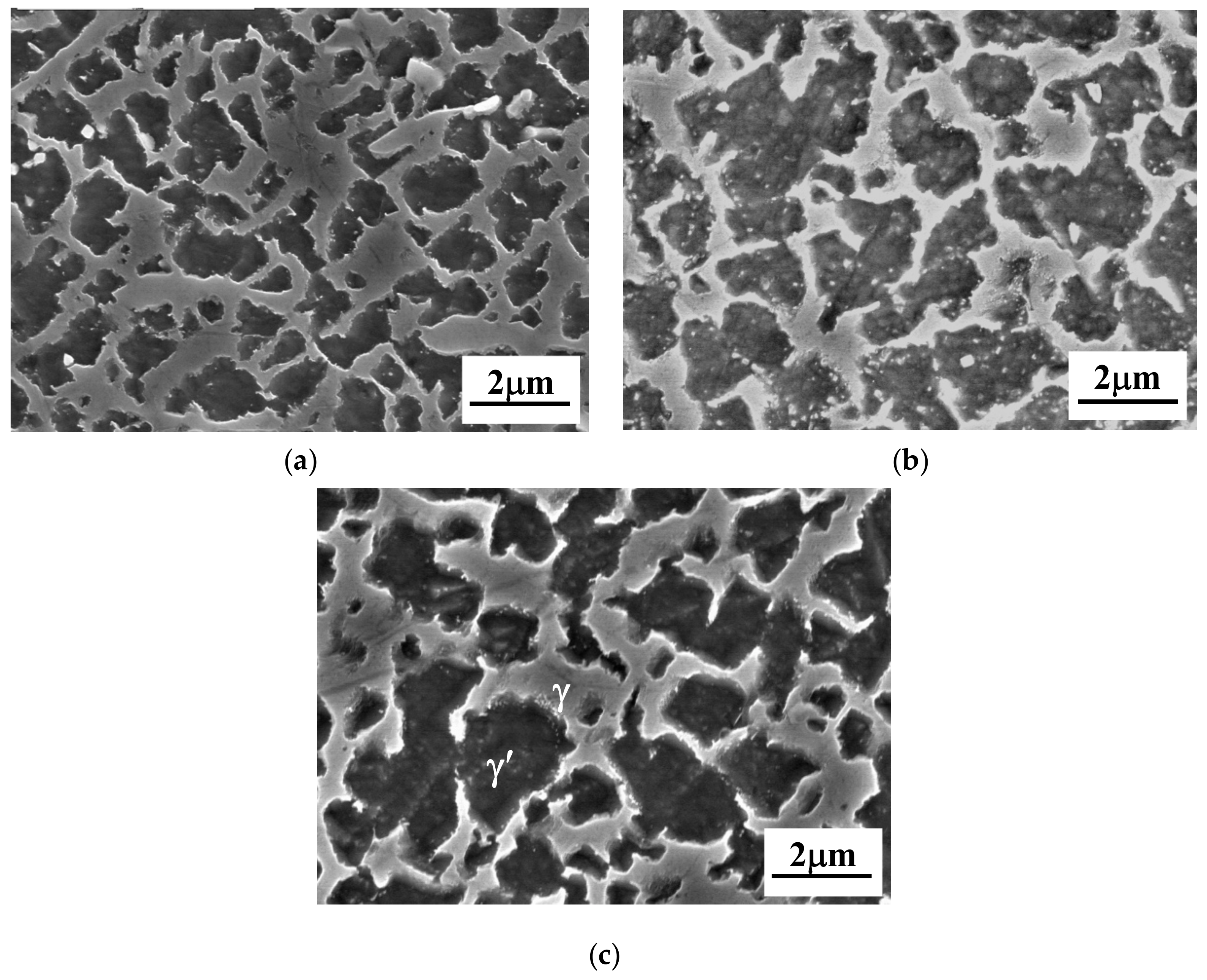
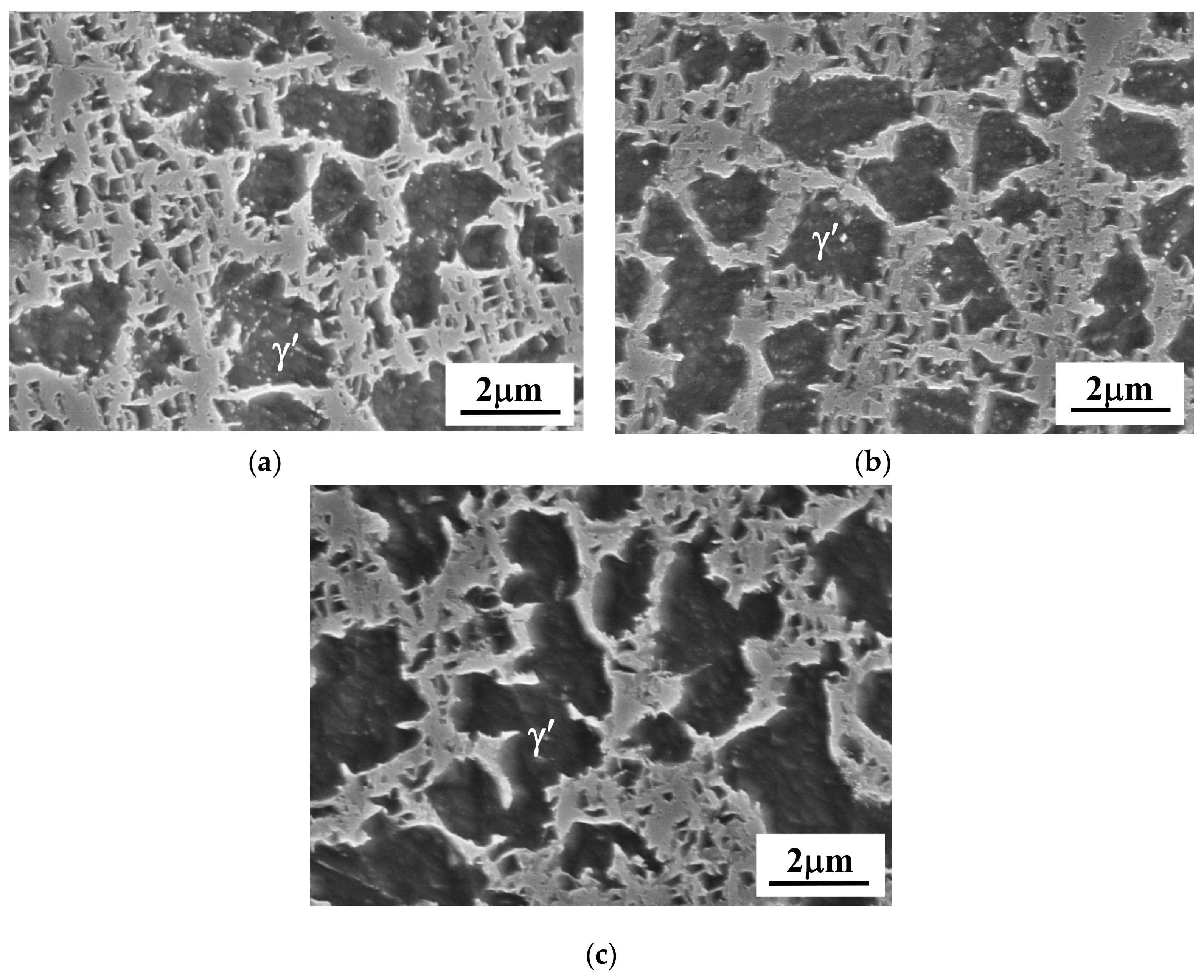
RHT was carried out on the precrept specimens with different levels of strain. To clarify the microstructural evolution during RHT, samples were taken and inspected by SEM and TEM, and a comparison was made among samples at different stages. First of all, the grain size of different samples after RHT was examined by optical microscope, and no substantial difference was detected compared with the initial microstructure. Figure 6 shows the morphology of γ′ precipitates in the DC with different creep stain. It can be seen that rafted γ′ was absent and cuboidal γ′ precipitates were uniformly dispersed in the γ matrix in the sample with accumulated strain of 0.03, which is almost similar to those of original microstructure. With the increase of accumulated strain to 0.05 or above, some γ′ precipitates of a smaller size were found in some localized regions, as indicated by the arrows shown in Figure 6b and c. Moreover, the morphology of these precipitates appears to be irregular. A similar phenomenon was also reported previously [30]. It was found that the γ′ particles in the sample prepared by epitaxial laser metal forming also had an irregular morphology after heat treatment, which was associated with the internal stress induced by rapid cooling. In the present study, creep deformation was induced, and internal stress may still remain after RHT, especially in the sample with high creep strain. The morphology and distribution of γ′ particles in the ID region after RHT is shown in Figure 7. Two types of particles of different size coexisted, which was similar to that in the initial microstructure. However, the shape of precipitates became more irregular, especially in the sample with large precrept strain as can be seen in Figure 7c. Moreover, the size of γ′ particles in this sample seems to be still larger than that of the initial microstructure.
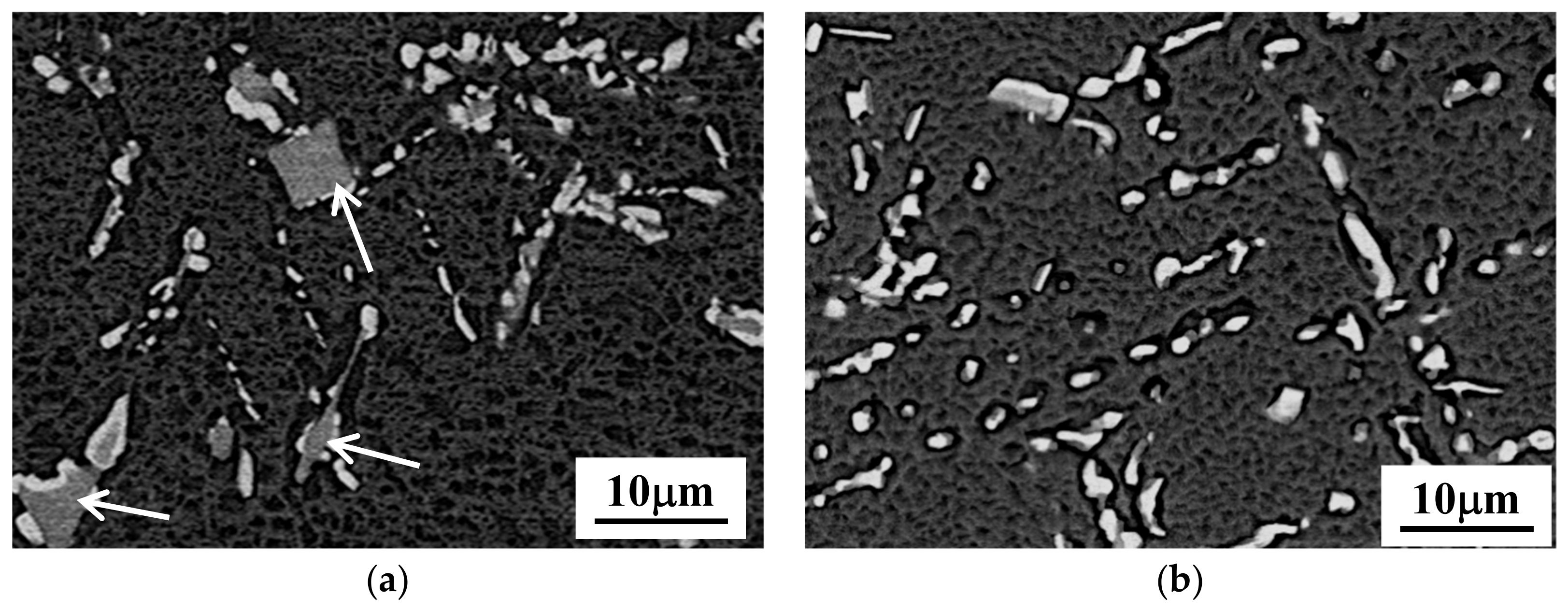
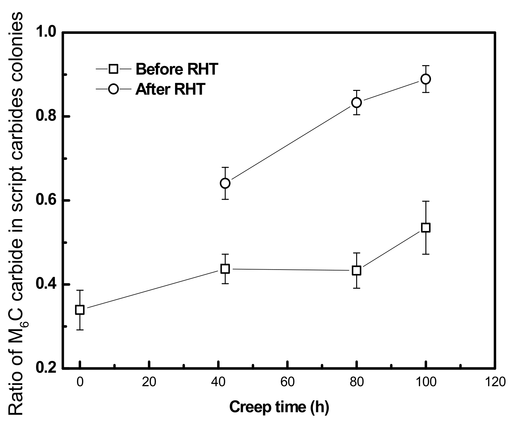
The carbide transformations before and after RHT were also examined in different samples. The SEM micrographs shown in Figure 8 provide one typical example for revealing the carbide transformation in the sample with precrept strain of 0.07. In Figure 8a, the blocky MC carbides can be easily found in the ID region, which is indicated by the arrows. However, the MC type carbides were almost absent after RHT in the same sample, as can be seen in Figure 8b. This implies that the MC type carbides transformed into M6C carbides during RHT. The dissolution temperature for MC carbides is above 128 °C according to the differential thermal analysis (DTA) results. Therefore, it is unlikely that RHT in the present study induced the dissolution of MC carbides but rather enhanced their decomposition. To quantitatively evaluate the transformation of carbides, the ratio of area fraction of M6C carbides to the total area fraction of carbide colonies within five inspected areas was measured by an image analysis approach. The result is summarized in Figure 9. It can be seen that the ratio of M6C carbides was increased gradually during the creep test. With the subsequent RHT, the ratio of M6C carbides significantly increases. This result demonstrates that MC type carbides will continuously transform into M6C type carbides with the thermally-aided diffusional process. RHT cannot reverse the carbide transformation.
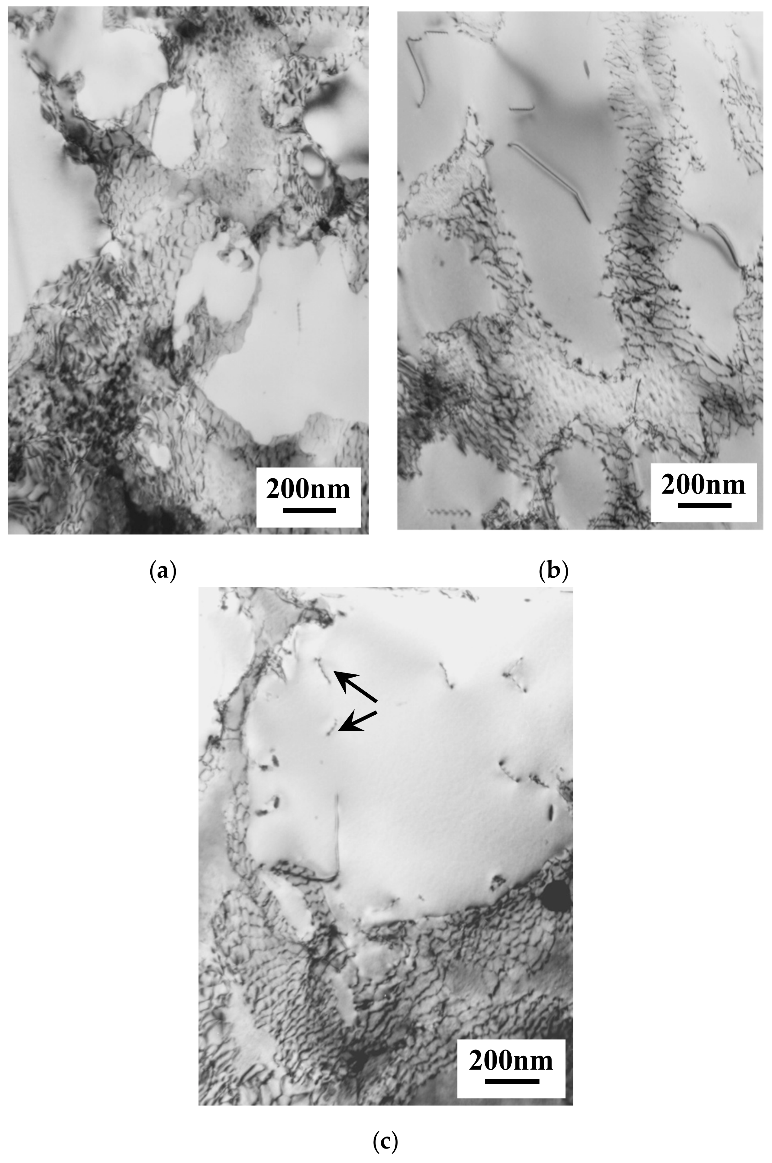
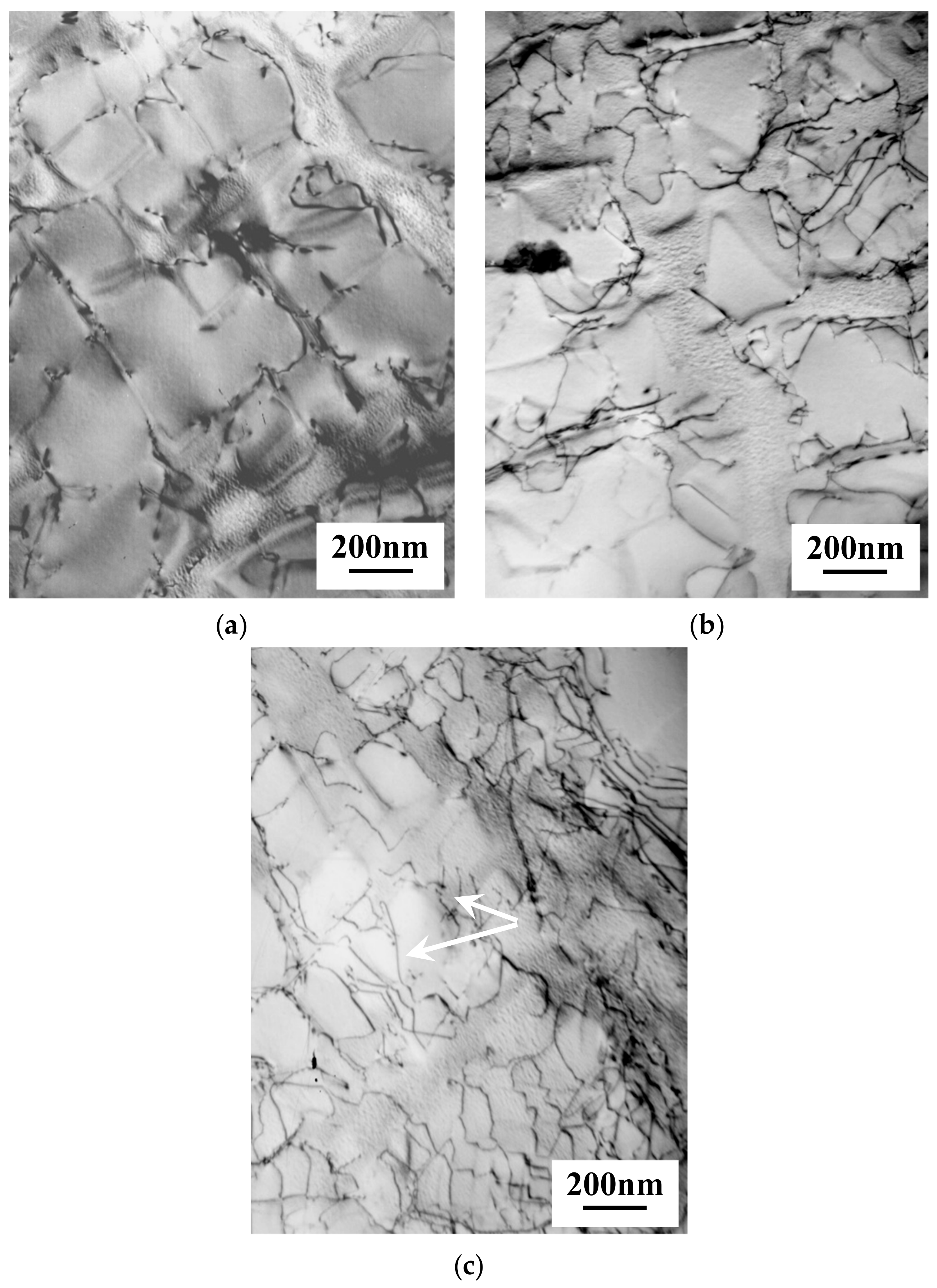
TEM micrographs shown in Figure 10 demonstrate the dislocation configuration in different samples after RHT. From these micrographs, we can see that dislocation networks formed during creep deformation were substantially removed after RHT regardless of the accumulated strain. However, it should be noticed that some dislocations still remain in the γ matrix channels and the γ/γ′ interfaces, especially in the sample with high accumulated creep strain, which is indicated by the arrows in Figure 10c. Survival of these dislocations from RHT may have an impact on the re-precipitation of γ′ particles during RHT. As mentioned above, there are some small γ′ precipitates presented in localized regions within the sample with high accumulated strain. These dislocations are regarded to be accountable for the formation of these small γ′ particles. It may provide preferential sites for the nucleation of γ′ particles and enhance the nucleation process. On the other hand, the γ′ precipitate sheared by dislocation pairs is not observed in these samples because the γ′ precipitates were newly formed during RHT. From this observation, we can see that RHT can effectively remove the dislocation networks in the sample with low accumulated creep strain. With the increase of precrept strain, a number of dislocations were still retained in the matrix channels after RHT.
3.4. Effect of RHT on the Creep Behavior of K465 Alloy
To evaluate the effectiveness of RHT, all precrept samples after RHT were creep-tested again at the same creep condition. The creep strain vs. strain rate curves of different samples are shown in Figure 11. The creep rupture time and minimum creep rate of samples with different accumulated strain are summarized in Table 2. From this result, we can see that the creep strain rate of all samples firstly declines to a minimum value and then rises with the increase of creep strain. This phenomenon can be explained by the movement of dislocations, namely, the mobile dislocation density and velocity of dislocations. It is of interest to note that the minimum creep strain rate of RHT samples is strongly dependent on the precrept strain. For instance, the strain rate curve of the sample with precrept strain of 0.03 is analogous to the sample with an unaltered initial microstructure. The minimum creep strain of these two samples is also found to be similar. With the increase of precrept strain, there is an apparent increase in the minimum creep strain rate when the RHT samples are crept again. On the other hand, the minimum creep rate is reversely proportional to the creep rupture time, which can be rationalized by the Monkman–Grant empirical relationship [31].
The present results manifest that the creep property of precrept K465 alloy can be rejuvenated to a certain level by performing RHT. With low accumulated strain, the creep resistance of K465 alloy after performing RHT is almost equivalent to the sample after standard heat treatment. However, RHT cannot fully rejuvenate the creep property when the accumulated strain reaches a certain level, which roughly corresponds to minimum strain rate of samples with initial microstructure. In other words, the effectiveness of RHT is strongly dependent on the accumulated strain level, which can be interpreted by the microstructure observation after RHT. Through performing RHT on samples with low accumulated strain, the precipitation behavior of γ′was almost similar to that after heat treatment, and dislocation networks were fully eliminated as is shown in Figure 6a and Figure 10a. On the other hand, the homogeneous precipitation was not reproduced in the samples with high accumulated strain after RHT, as is evident in Figure 6b,c. Moreover, a number of dislocations still remained in matrix channels. Therefore, this degraded microstructure will deteriorate the creep property of K465 alloy. Similar results were also previously reported on a single crystal Ni-base superalloy [32]. However, it is still not clear why the creep property of a sample with high accumulated strain cannot be fully rejuvenated by performing RHT. Perhaps some special measures should be taken during RHT—future work is needed to clarify this issue.
It should be noted that there is a large amount of carbides formed in the matrix, which also contribute to the high temperature strength of K465 alloy. As mentioned above, The MC type carbides tended to transform continuously into M6C carbides during creep, and RHT cannot alter this transformation behavior of carbides. As a consequence, the area fraction of M6C carbides increases noticeably. However, the carbides’ transformation may not significantly impair the creep resistance of K465 alloy concerning the creep results shown in Table 2 and Figure 11. One previous study claimed that the creep voids were prone to initiate in the vicinity of MC carbides during creep deformation, whereas M6C carbides reduced the stress concentration at the interfaces and inhibited the formation of creep voids [13]. The carbide transformation was partially beneficial to improving the creep property. However, this effect should be further verified in a long-term creep test.
4. Conclusions
Rejuvenation heat treatment is carried out on a polycrystalline Ni-based superalloy K465 in the present study. Based on the microstructure examination and creep property after RHT, the conclusions which can be obtained are as follows:
- During creep deformation, the γ′ precipitates in the dendritic core underwent severe changes, and γ′ rafting occurred with the increase of creep strain. Meanwhile, the formation of dislocation networks was observed even in the sample with low creep strain. With the accumulation of creep strain, γ′ precipitates were sheared by a larger number of dislocations. Simultaneously, MC carbides continuously transformed into M6C during creep.
- By performing RHT, the distribution and size of γ′ in the dendrite core could be reproduced to be almost similar to the heat-treated condition, and dislocation networks were effectively eliminated in the sample with low accumulated strain. However, the microstructure of samples with high accumulated creep strain was not fully restored to the original status after RHT. On the other hand, the carbides transformation from MC to M6C was further enhanced during RHT.
- The creep property after RHT is closely associated with the precrept strain. A critical value exists for K465 alloy, which roughly corresponds to the minimum creep rate of a sample with initial microstructure. If accumulated strain exceeds this value, the creep property cannot be fully re-established. The carbide transformation from MC to M6C to some extent may contribute to the improvement of creep resistance of K465 alloy. However, this effect should be further verified by long-term creep tests.
Author Contributions
L.W.; methodology, data collection and formal analysis, Y.L.; manuscript preparation, J.L.; project management, manuscript revision. All authors have read and agreed to the published version of the manuscript.
Funding
This research received no external financial support.
Acknowledgments
The fruitful discussion with Qi Zheng is gratefully acknowledged.
Conflicts of Interest
The authors declare no conflict of interest.
References
- Linul, E.; Movahedi, N.; Marsavina, L. On the lateral compressive behavior of empty and ex-situ Al foam-filled tubes at high temperature. Materials 2018, 11, 554. [Google Scholar] [CrossRef] [PubMed] [Green Version]
- Szlanscik, A.; Katona, B.; Majlinger, K.; Orbulov, I.N. Compressive behavior and microstructural characteristics of iron hollow sphere filled Al matrix syntactic foams. Materials 2015, 8, 7926–7937. [Google Scholar] [CrossRef] [Green Version]
- Movahedi, N.; Murch, G.E.; Belova, I.V.; Fiedler, T. Effect of heat treatment on the compressive behavior of Zn alloy ZA27 syntactic foam. Materials 2019, 12, 792. [Google Scholar] [CrossRef] [PubMed] [Green Version]
- Movahedi, N.; Taherishargh, M.; Belova, I.; Murch, G.E.; Fiedler, T. Mechanical and microstructure characterization of an AZ91-activated carbon syntactic foam. Materials 2019, 12, 3–10. [Google Scholar]
- Ewans, R.W.; Wilshire, B. Creep of Metals and Alloys; Institute of Metals: Chicago, IL, USA, 1985. [Google Scholar]
- Reed, R.C.; Cox, D.C.; Rae, C.M.F. Damage accumulation during creep deformation of a single crystal superalloy at 1150 °C. Mater. Sci. Eng. A 2007, 448, 88–96. [Google Scholar] [CrossRef]
- Steuer, S.; Hervier, Z.; Thabart, S.; Castaing, C. Creep behavior under isothermal and non-isothermal conditions of AM3 single crystal superalloy for different solutioning cooling rates. Mater. Sci. Eng. A 2014, 601, 145–152. [Google Scholar] [CrossRef]
- Liu, L.R.; Jin, T.; Zhao, N.R.; Wang, Z.H.; Sun, X.F.; Guan, H.R.; Hu, Z.Q. Effect of carbon addition on the creep properties in a Ni-based single crystal superalloy. Mater. Sci. Eng. A 2004, 385, 105–112. [Google Scholar] [CrossRef]
- Kim, I.S.; Choi, B.G.; Seo, S.M.; Kim, D.H.; Jo, C.Y. Influence of heat treatment on microstructure and tensile properties of conventionally cast and directionally solidified superalloy CM247LC. Mater. Lett. 2008, 62, 1110–1113. [Google Scholar] [CrossRef]
- Graverend, J.-B.L.; Cormier, J.; Kruch, S.; Gallerneau, F.; Mendez, J. Microstructural parameters controlling high-temperature creep life of the nickel-base single-crystal superalloy MC2. Metall. Mater. Trans. A 2012, 43, 3988–3997. [Google Scholar] [CrossRef]
- Acharya, M.V.; Fuchs, G.E. The effect of long-term thermal exposures on the microstructure and properties of CMSX-10 single crystal Ni-base superalloy. Mater. Sci. Eng. A 2004, 381, 143–153. [Google Scholar] [CrossRef]
- Choi, B.G.; Kim, I.S.; Kim, D.H.; Jo, C.Y. Temperature dependence of MC decomposition behavior in Ni-base superalloy GTD 111. Mater. Sci. Eng. A 2008, 478, 329–335. [Google Scholar] [CrossRef]
- He, L.Z.; Zheng, Q.; Sun, X.F.; Guan, H.R.; Hu, Z.Q.; Tieu, A.K.; Lu, C.; Zhu, H.T. Effect of carbides on the creep properties of a Ni-base superalloy M963. Mater. Sci. Eng. A 2005, 397, 297–304. [Google Scholar] [CrossRef]
- Henderson, P.; Berglin, L.; Jansson, C. On rafting in a single crystal nickel-base superalloy after high and low temperature creep. Scr. Mater. 1999, 40, 229–234. [Google Scholar] [CrossRef]
- Shui, L.; Xu, Y.C.; Hu, Z.Q. Dislocation structure in a single crystal nickel base superalloy during high cycle fatigue at 870 °C. Rare Met. Mater. Eng. 2018, 47, 1054–1058. [Google Scholar]
- Nategh, S.; Sajjadi, S.A. Dislocation network formation during creep in Ni-base superalloy GTD-111. Mater. Sci. Eng. A 2003, 339, 103–108. [Google Scholar] [CrossRef]
- Lu, X.D.; Du, J.H.; Deng, Q. High temperature structure stability of GH4169 superalloy. Mater. Sci. Eng. A 2013, 559, 623–628. [Google Scholar] [CrossRef]
- Kim, M.T.; Chang, S.Y.; Won, J.B. Effect of HIP process on the microstructure evolution of a Ni-base superalloy. Mater. Sci. Eng. A 2006, 441, 126–134. [Google Scholar] [CrossRef]
- Bor, H.Y.; Hsu, C.; Wei, C.N. Influence of HIP on the fracture transitions in the fine grain Mar-M247 superalloys. Mater. Chem. Phy. 2004, 84, 284–290. [Google Scholar] [CrossRef]
- Shi, Z.; Liu, S.; Li, J. Rejuvenation Heat Treatment of the Second-Generation Single-Crystal Superalloy DD6. Acta Metall. Sin. 2015, 28, 1278–1285. [Google Scholar] [CrossRef] [Green Version]
- Stevens, R.A.; Flewitt, P.E. Intermediate regenerative heat treatment for extending the creep life of the superalloy IN-738. Mater. Sci. Eng. 1981, 50, 271–284. [Google Scholar] [CrossRef]
- Mathew, M.D.; Bhanu Sankara Rao, K.; Mannan, S.L. Creep properties of service-exposed alloy 625 after re-solution annealing treatment. Mater. Sci. Eng. A 2004, 372, 327–333. [Google Scholar] [CrossRef]
- Girdwood, R.B.; Evans, R.W. Recovery of creep properties of the nickel-base superalloy nimonic 105. Int. J. Press. Vessel. Pip. 1996, 66, 141–153. [Google Scholar] [CrossRef]
- Yao, Z.; Degnan, C.C.; Jepson, M.A.E.; Thomson, R. Microstructure and chemical rejuvenation of a Ni-based superalloy. Metall. Mater. Trans. A 2016, 47, 6330–6338. [Google Scholar] [CrossRef] [Green Version]
- GB/T2039:2012—Metallic Materials—Uniaxial Creep Testing Method in Tension; The Technical Committee on Steels of Standardization of China: Beijing, China, 2012.
- He, L.Z.; Zheng, Q.; Sun, X.F.; Guan, H.R.; Hu, Z.Q.; Tieu, A.K.; Lu, C.; Zhu, H.T. Effect of heat treatment on microstructures and tensile properties of Ni-base superalloy M963. Mater. Sci. Eng. A 2005, 398, 128–136. [Google Scholar] [CrossRef]
- Yang, J.X.; Zheng, Q.; Sun, X.F.; Guan, H.R.; Hu, Z.Q. Relative stability of carbides and their effects on the properties of K465 superalloy. Mater. Sci. Eng. A 2006, 429, 341–347. [Google Scholar] [CrossRef]
- Zhang, J.X.; Murakumo, T.; Koizumi, Y.; Kobayashi, T.; Harada, H.; Masaki, S. Interfacial dislocation networks strengthening a fourth-generation single-crystal TMS-138 superalloy. Metall. Mater. Trans. A 2002, 33, 3741–3746. [Google Scholar] [CrossRef]
- Lasalmonie, A.; Strudel, J.L. Interfacial dislocation networks around precipitatesin nickel-base alloys. Philos. Mag. 1975, 32, 937–949. [Google Scholar] [CrossRef]
- Gaumann, M.; Henry, S.; Cleton, F.; Wagniere, J.D.; Kurz, K. Epitaxial laser metal forming: Analysis of microstructure formation. Mater. Sci. Eng. A 1999, 271, 232–241. [Google Scholar] [CrossRef]
- Monkman, E.C.; Grant, N.J. An Empirical Relationship between Rupture Life and Minimum Creep Rate in Creep-Rupture Tests. Proc. ASTM 1956, 56, 593–620. [Google Scholar]
- Ruttert, B.; Horst, O.; Lopez-Galilea, I.; Langenkamper, D.; Kostka, A.; Somsen, C.; Goerler, J.V.; Ali, M.A.; Shchyaglo, O.; Steinbach, I.; et al. Rejuvenation of single-crystal Ni-base superalloy turbine blades: Unlimited service life? Metall. Mater. Trans. A 2018, 426, 4262–4273. [Google Scholar] [CrossRef]
Figure 1.
SEM micrographs showing the initial microstructure of K465 alloy after heat treatment: (a) γ′ precipitates in the dendrite core (DC); (b) γ′ precipitates in interdendritic region; (c) back scattering electron (BSE) SEM image showing the different types of carbides and (d) EPMA analysis on the composition of carbides.

Figure 2.
Typical creep time vs. strain curve (a) and strain vs. strain rate curve (b) of K465 alloy, dashed lines showing the interrupted test with different creep strain.
Figure 2.
Typical creep time vs. strain curve (a) and strain vs. strain rate curve (b) of K465 alloy, dashed lines showing the interrupted test with different creep strain.

Figure 3.
SEM micrographs showing the morphology of γ′ phase in the DC with creep strain of (a) 0.03, (b) 0.05, and (c) 0.07.
Figure 3.
SEM micrographs showing the morphology of γ′ phase in the DC with creep strain of (a) 0.03, (b) 0.05, and (c) 0.07.


Figure 4.
SEM micrograph showing the morphology of γ′ phase in interdendritic region of the sample with creep strain of (a) 0.03, (b) 0.05, and (c) 0.07.
Figure 4.
SEM micrograph showing the morphology of γ′ phase in interdendritic region of the sample with creep strain of (a) 0.03, (b) 0.05, and (c) 0.07.

Figure 5.
TEM micrographs showing the dislocation configuration in the samples with creep strain of (a) 0.03, (b) 0.05, and (c) 0.07. The arrows indicate the dislocations cutting into γ′ particles.
Figure 5.
TEM micrographs showing the dislocation configuration in the samples with creep strain of (a) 0.03, (b) 0.05, and (c) 0.07. The arrows indicate the dislocations cutting into γ′ particles.

Figure 6.
SEM micrographs showing the morphology of the γ′ phase in the dendritic core with creep strain of (a) 0.03, (b) 0.05, and (c) 0.07 after rejuvenation heat treatment (RHT). Arrows indicate the γ′ particles with small size and irregular morphology.
Figure 6.
SEM micrographs showing the morphology of the γ′ phase in the dendritic core with creep strain of (a) 0.03, (b) 0.05, and (c) 0.07 after rejuvenation heat treatment (RHT). Arrows indicate the γ′ particles with small size and irregular morphology.

Figure 7.
SEM micrographs showing the morphology of the γ′ phase in the interdendritic region of sample with precrept strain of (a) 0.03, (b) 0.05, and (c) 0.07 after RHT.
Figure 7.
SEM micrographs showing the morphology of the γ′ phase in the interdendritic region of sample with precrept strain of (a) 0.03, (b) 0.05, and (c) 0.07 after RHT.

Figure 8.
SEM micrographs showing the carbides distribution in the sample with precrept strain of 0.07(a) before RHT and (b) after RHT. Arrows indicate the blocky MC carbides.
Figure 8.
SEM micrographs showing the carbides distribution in the sample with precrept strain of 0.07(a) before RHT and (b) after RHT. Arrows indicate the blocky MC carbides.

Figure 9.
Carbides transformation behavior during creep and RHT.

Figure 10.
TEM micrographs showing the dislocation configuration in the samples with strain of (a) 0.03, (b) 0.05, and (c) 0.07 after RHT. Arrows pointing out the dislocations retained in matrix.
Figure 10.
TEM micrographs showing the dislocation configuration in the samples with strain of (a) 0.03, (b) 0.05, and (c) 0.07 after RHT. Arrows pointing out the dislocations retained in matrix.

Figure 11.
Creep rate curves of the samples after RHT.


Table 1.
Nominal chemical composition of K465 alloy (wt %).
| C | Cr | Al | Ti | Mo | W | Co | Nb | Ni |
|---|---|---|---|---|---|---|---|---|
| 0.20 | 8.95 | 5.76 | 2.90 | 2.06 | 11.0 | 9.80 | 1.12 | Balanced |
Table 2.
Creep property of samples after RHT.
| Samples | Creep Rupture Time, h | Minimum Creep Rate,1/h |
|---|---|---|
| After heat treatment | 112 | 1.01 × 10⁻⁴ |
| With 0.03 creep strain + RHT | 105 | 1.31 × 10⁻⁴ |
| With 0.05 creep strain + RHT | 84 | 2.73 × 10⁻⁴ |
| With 0.07 creep strain + RHT | 38 | 5.24 × 10⁻⁴ |
© 2020 by the authors. Licensee MDPI, Basel, Switzerland. This article is an open access article distributed under the terms and conditions of the Creative Commons Attribution (CC BY) license (http://creativecommons.org/licenses/by/4.0/).
Share and Cite
MDPI and ACS Style
Wang, L.; Liu, Y.; Liang, J. Effect of Rejuvenation Heat Treatment on the Creep Property and Microstructural Evolution of a Ni-Base Superalloy. Appl. Sci. 2020, 10, 1187. https://0-doi-org.brum.beds.ac.uk/10.3390/app10031187
AMA Style
Wang L, Liu Y, Liang J. Effect of Rejuvenation Heat Treatment on the Creep Property and Microstructural Evolution of a Ni-Base Superalloy. Applied Sciences. 2020; 10(3):1187. https://0-doi-org.brum.beds.ac.uk/10.3390/app10031187
Chicago/Turabian StyleWang, Linning, Yuan Liu, and Jingjing Liang. 2020. "Effect of Rejuvenation Heat Treatment on the Creep Property and Microstructural Evolution of a Ni-Base Superalloy" Applied Sciences 10, no. 3: 1187. https://0-doi-org.brum.beds.ac.uk/10.3390/app10031187
Note that from the first issue of 2016, this journal uses article numbers instead of page numbers. See further details here.