Article

Experimental and Numerical Investigations on the Local Direct Leakage Process of Rotary Regenerative Air Preheater

1
State Key Laboratory of Multiphase Flow in Power Engineering, Xi’an Jiaotong University, Xi’an 710049, China
2
Dongfang Electric Corporation Dongfang Boiler Group Co., Ltd., Chengdu 611731, China
*
Author to whom correspondence should be addressed.
Submission received: 10 January 2020 / Revised: 12 February 2020 / Accepted: 19 February 2020 / Published: 23 February 2020

Abstract

:
An inherent defect of the operating rotary air preheaters (RAPH) is known as leakage, which seriously hinders the efficient and safe operation of RAPH. It is significant for the estimation of the direct leakage to determine the effects of different structure parameters of sealing sheets and different operation parameters of a RAPH. A direct leakage set-up was built and a three-dimensional numerical model was established to explore the local direct air leaking process of rotary regenerative air preheater and study the effects of geometrical and operational parameters on the leakage. The numerical simulation using the transition k-kl-ω turbulence model was verified by the experimental results. The results show that the local direct air leakage mainly depends on the total pressure difference between the two sides of the seal instead of the one-side pressure. The air leakage can be significantly reduced by narrowing the leakage gap. The increase in the number of sealing sheets can reduce the air leakage own to the increase in the leakage resistance. The increase in the spacing between the adjacent sealing sheets can enlarge the recirculation zone and increase the energy loss of mainstream, greatly reducing the local direct air leakage. Due to the different size recirculation zone formation and streamline curvature induced by sealing sheet, the effect of bending angle on the direct air leakage varies. To obtain lower leakage rate, it is recommended for the rotor of tri-sectional air preheater to pass through flue gas section, secondary-air section, and primary-air section in sequence.

1. Introduction

The improvement of the energy conversion efficiency in the process of energy consumption is of great significance and has attracted increasing attention in the global energy shortage scenario [1]. As an indispensable device in the coal-fired power plant, rotary air preheaters (RAPH) are widely applied to recover the waste heat from flue gas and heat combustion air owing to its compactness and superior performance [2,3]. The combustion air heated by RAPH can not only enhance the combustion, but also is necessary for drying and transportation of the pulverized coal [4]. The efficient operation of RAPH can improve the overall efficiency of the boiler by 5–10% [5]. However, an inherent defect of the operating RAPH is known as leakage, which would seriously hinder the efficient and safe operation of RAPH.
The leakage in the RAPH includes the direct and entrained parts. As shown in Figure 1a, there are six general leakage paths in the RAPH. Under certain pressure differences, the leak streams 1–2 and 3–4 take place in the gap between the stationary and rotating structures, which are called the direct leakage. The leak streams 5–6 represent the leakage carried by the rotor void during rotor rotation, called entrained leakage [6,7]. The air leakage of RAPH will cause a series of problems, such as the decrease in heat transfer efficiency, increase in fan power consumption, and aggravation of low-temperature corrosion [8]. To reduce the indirect leakage, the rotational speed of RAPH is usually set as low as possible under the premise of efficient operation. By contrast, owing to the mushroom deformation of the rotor and the fouling of the matrix, both of the leaking area and the pressure difference would be enlarged [9,10,11,12], which would result in a large direct leakage accounting for almost 80% of the whole [13]. To reduce the direct leakage, a number of methods have been proposed, among which multi-seal sealing system (Figure 1b) has more advantages and is most widely employed.
Much work has been done on the leakage distributions and their effects on the efficiency of the RAPH. Faris et al. [14] proposed a method to measure the gap size of direct air leakage by installing probes on each sector plate. Several studies have been conducted on air leakage by Skiekpo, including the methods for the gap monitoring [15], the evaluation of leakage distribution [16], the effect of leakage distribution on the thermal performance [17], as well as the effect of the reduction in sealing gap size on RAPH [6]. They found that radial gap has a significant effect on leakage and the reduction in radial gap size would improve the efficiency of the power plant. Shah et al. [18] showed that various leakages could cause significant decrease in the heat transfer efficiency of the RAPH, and the decline in effectiveness depends on the leakage type. Boštjan et al. [5] investigated the effect of air leakage on the flue gas composition and the outlet temperature of the RAPH. Their results showed that the cold end leakage could significantly reduce the flue gas temperature, whereas the hot end leakage has less effect on the flue gas temperature. Maharaj et al. [19] established a simplified flow path model for numerical calculation of direct air leakage. It is found that the results calculated by empirical formula are lower than the simulated values due to the ignorance of the gradual change of the gap size along the radial direction. Zhang et al. [20] proposed an online application approach to monitor the gap size and estimate the direct leakage of the air preheater. Du et al. [21] established a model by coupling the air leakage and the thermodynamics to investigate the leakage matter. The results show that the total leakage of quad-sectional air preheater is less than that of tri-sectional by 33.1%. Gao et al. [22] conducted an analysis of the air leakage on boiler efficiency, and indicated that the change of the air leakage coefficient of the hot end has a greater impact on the boiler efficiency than the cold end. However, several studies have considered the effects of different structure parameters of sealing sheets, which are quite important for the estimation and calculation of the direct leakage. Cai et al. [13] carried out numerical simulation and experimental research on the direct air leakage in an RAPH. They assumed that the orifice coefficient and the engineering modifying factor are related to the inlet pressure and sealing gap size, and neglected the effect of the spacing value of adjacent sealing sheets, whereas some other factors, i.e., the bending angle of the sealing sheets and the spacing between the adjacent sealing sheets, could also greatly affect the direct leakage, which are not reported in previous studies.
Therefore, the investigations on the multi-seal sealing system are far from meeting the application requirements. In this study, the effects of the gap size, the pressure difference, the spacing between the adjacent sealing sheets, the number and bending angle of the sealing sheets on the direct leakage and the orifice coefficient of the preheater have been experimentally and numerically investigated. The aim of this paper is to provide a reference for the accurate prediction of the direct air leakage of the regenerative rotary air preheater.

2. Experimentation

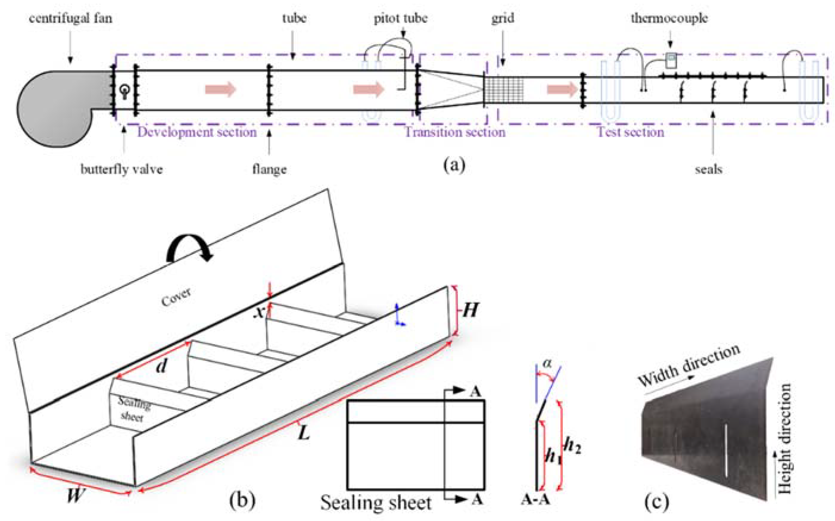
2.1. Experimental System

As shown in Figure 2a, the experimental system is mainly composed of a centrifugal fan, a developing section, a transition section and a test section. Driven by the pressure difference, direct leakage occurs from the high pressure air side to the low pressure gas side through the gap between the sealing sheets and the outer casing. The centrifugal fan can ensure adequate pressure and flow rate of air. A butterfly valve by which the air pressure can be adjusted was installed between the outlet of the centrifugal fan and the inlet of the developing section. The developing section was to ensure air reach the fully developed state and ensure accurate measurement. The transition section was installed between the developing section and the test section to ensure a good connection. In addition, a grid was installed at the entrance of the transition section to obtain uniform and stable flow field at the inlet of the test section. The test section (Figure 2b) is rectangular cross section with a width and a height of 400 mm and 175 mm, respectively. The inner upper surface of the test section was to model the inner surface of the sector plate or circular arc plate of the actual air preheater. The distance between the upper end of the sealing sheets and the inner upper surface of the cover plate could be adjusted to model the leakage gap size of the actual air preheater. The relevant parameters of the sealing sheets were also adjustable. Besides, all connecting flanges in the experimental system were sealed with ethylene-vinyl acetate copolymer sponge. The practical sealing sheet (Figure 2c) was made of Corten Steel and characterized by high strength and corrosion resistance.
The distance (d) between adjacent sealing sheets gradually increases along the radial direction, so the sealing sheet length of 400 mm is selected to study the direct air leakage at different segmentation in the radial direction. As shown in Table 1, the structural and operating parameters in the experiment, the distance between adjacent sealing sheets d, the sealing number Z, the gap size x, the bending angle α, and the total pressure difference Δptot were set based on the widely used real RAPH.

2.2. Experimental Principles

The air mass flow rate was measured by the Pitot tube installed on the fully developed region of the round pipe. The static pressure on both sides of the sealing sheets was measured by using a U-type pressure gauge. The temperature of the air was measured by a K-type thermocouple installed at the entrance of the experimental section. The air density at the inlet of the test section can be calculated based on the local absolute pressure and temperature.
According the Bernoulli equation, the air mass flow rate can be calculated by using the measured dynamic pressure and the cross-sectional area of the flow path. Due to the energy loss in the real process, the measured flow rate is always not equal to the calculated one. The orifice coefficient Cd is defined to correct the flow rate calculated from the Bernoulli equation:
C d = Q exp / Q i d e
Q i d e = A 2 ρ Δ p t o t / Z
where Qexp and Qide are the mass flow rates of air leakage by the measurement and the calculation, respectively; A is the leakage area; ρ is the air density; Z is the number of sealing sheets; and Δptot is the total pressure difference between the inlet and outlet of flow path.

3. Simulation

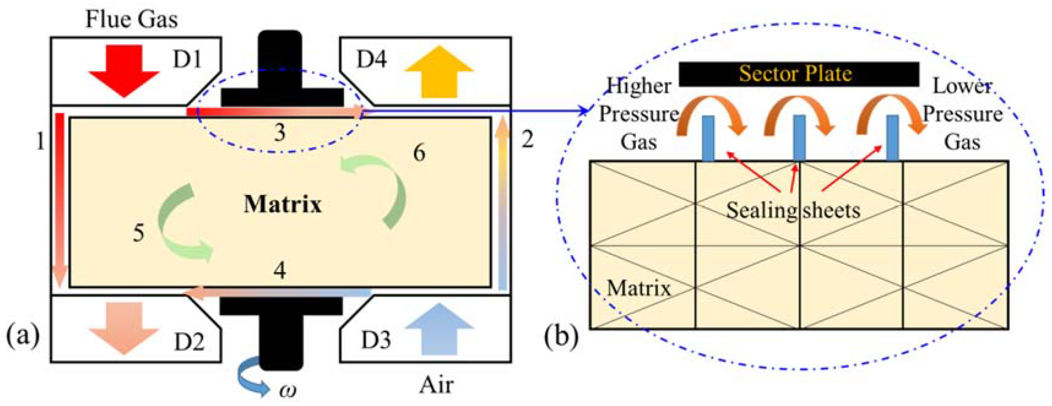
3.1. Physical Model and Governing Equations

As shown in Figure 2b, a physical model used for numerical simulation is a rectangular cross section flow path in which the sealing sheets are embedded. The flow path length L, the width W, and the heights h2 and h1 are 1300 mm, 400 mm, 150 mm, and 120 mm, respectively. The height of the flow path H can be adjusted to change the gap size.
The following simplifications and assumptions are made in the numerical simulation calculation.
  • Both the spacing of the adjacent sealing sheets and the gap size between sector plate and sealing sheet top end keep constants at a position of short length along the radial direction.
  • The fluid is an incompressible Newtonian fluid.
  • The fluid flow is in a turbulent state.
Continuity, energy, momentum, and gas state equations to describe the leakage process are as follows,
div ( ρ U ) = 0
div ( ρ U T ) = ρ div U + div ( λ grad U ) + Φ
div ( U U ) = div ( υ grad U ) 1 ρ p x i
p = R T V m b a T 0.5 V m ( V m + b )
where υ, λ, and Φ are the kinematic viscosity, the thermal conductivity, and the dissipation function, respectively; a and b are van der Waals constants. Other main symbols can be seen in the Appendix A.
Because the pressure of leaking air is higher than that of atmospheric pressure, the ideal gas state equation is not proper anymore in calculation the gas pressure. Equation (6) is also called the R-K equation, which is generally used to predict the pressure of non-ideal gas and the prediction accuracy is better for non-polar gas. As the air contains a lot non-polar gas N2 and O2, almost 4 to 1 in volume ratio, we applied the R-K equation to calculate the air pressure. In the computation, the quadratic upstream interpolation for convective kinetic scheme is used to interpolate the convective terms. The semi-implicit method for pressure-linked equations consistent algorithm is used for the pressure-velocity decoupling.

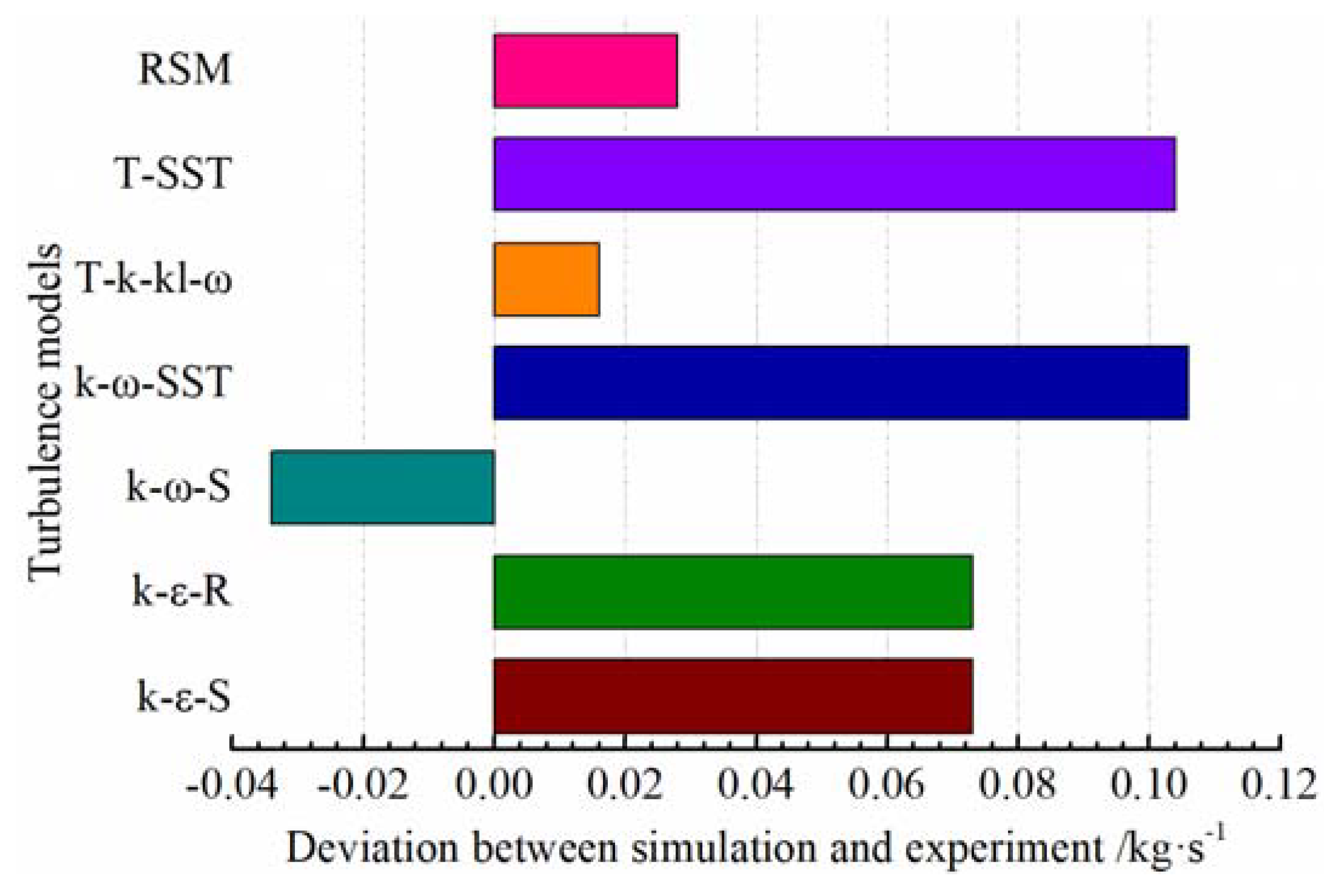
3.2. Turbulence Model and Boundary Conditions

Each turbulence model has its own application scope. The k-ε model and the k-ω model are two-equation eddy viscosity models widely used for incompressible and compressible flow close to the wall, and the accuracy and stability of the Transition-SST model in the near-wall region is superior to the standard k-ω model. The three-equation Transition k-kl-ω model based on the standard k-ω model is applicable to wall-constrained and jet flow, as the effect of disturbance to the Reynolds stress is added into this model [23].
The inlet and outlet of the flow path were set as the pressure inlet and the pressure outlet, respectively. The wall surface is adiabatic. The inlet air temperature is 308.15 K. All the numerical simulations will be performed on the software Fluent 16.0. The preparatory works before the simulation are supported by the software SolidWorks and ICEM. The steady-state solver based on pressure is used to solve the governing equations in this study.

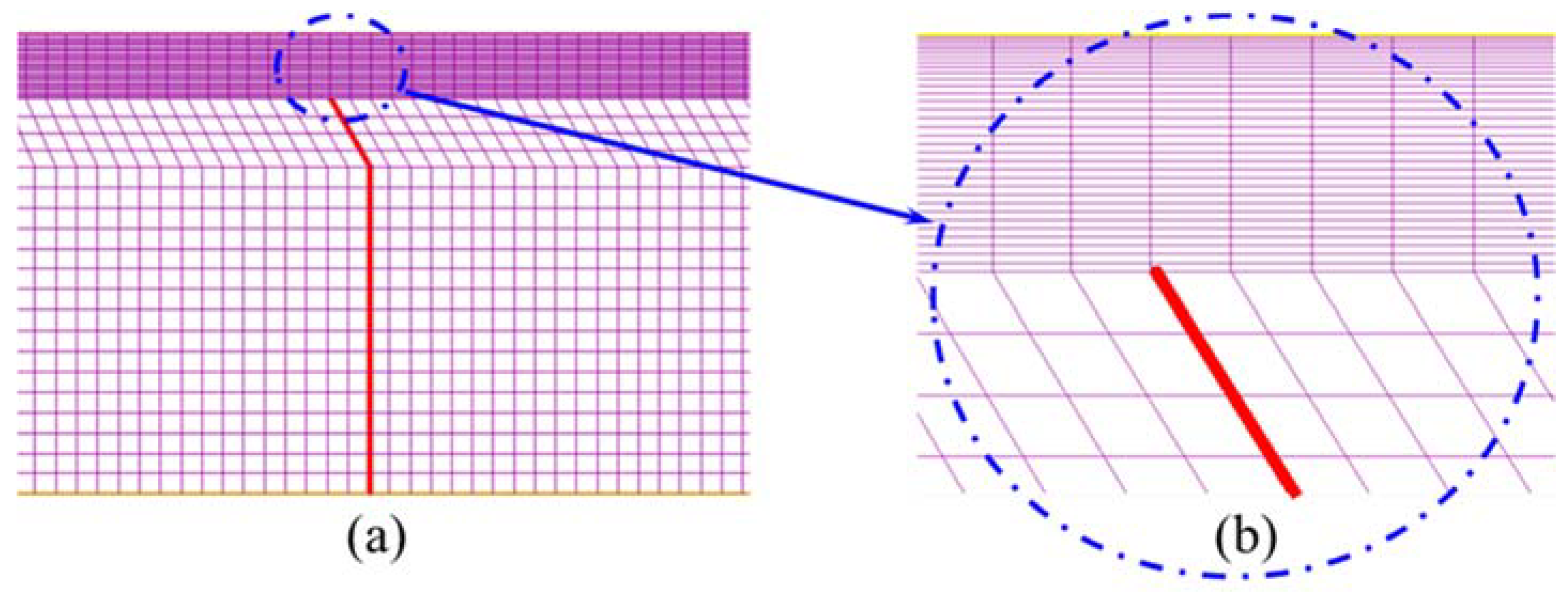
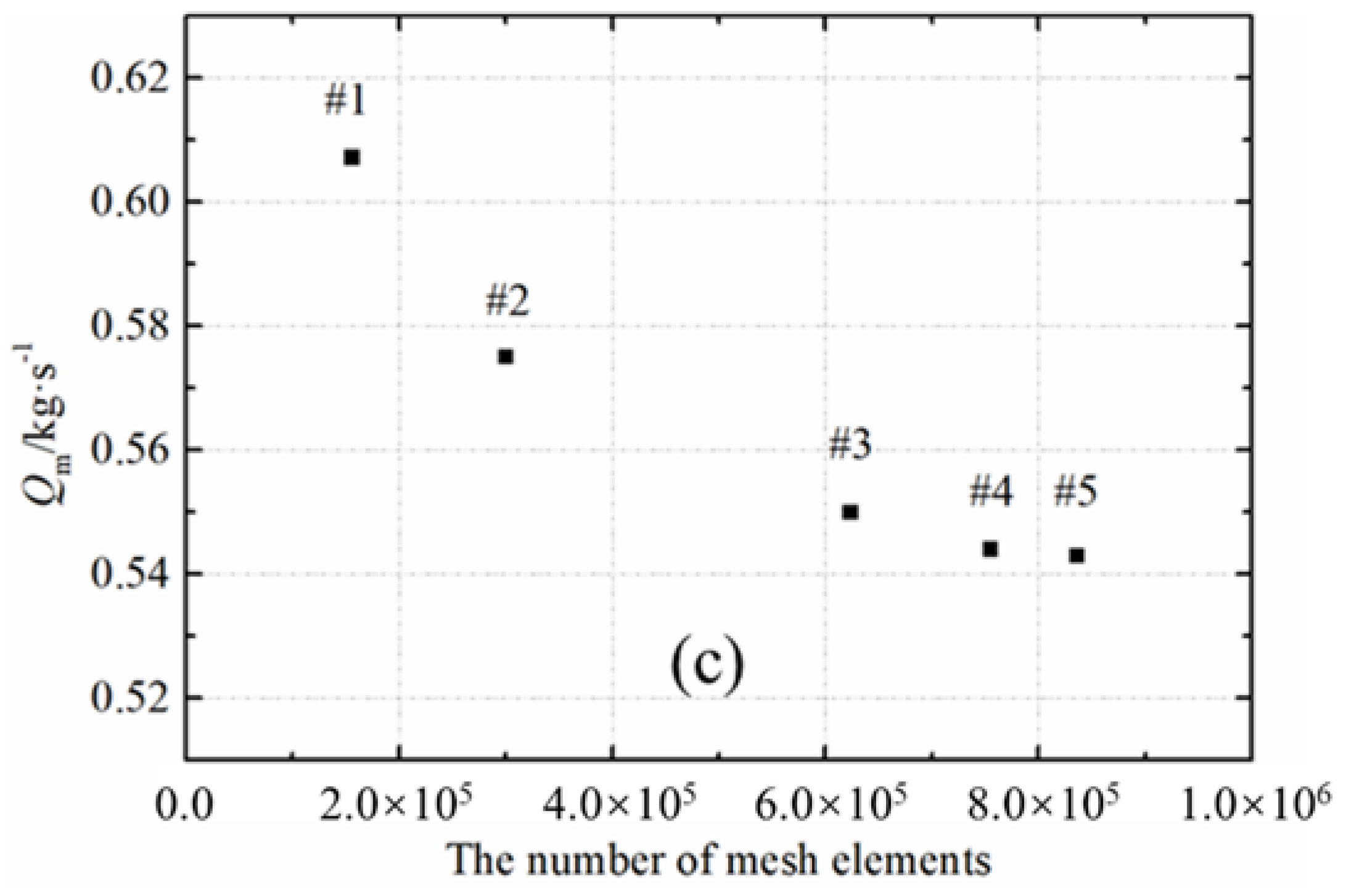
3.3. Meshing and Independence Verification

In this study, the structured mesh (Figure 3a) is used and local mesh at the position of the gap is refined (Figure 3b). As shown in Figure 3c, mesh independence test is performed and the results show that the grid-independent results can be obtained when the mesh element number exceeds 750,000.
To achieve the most suitable turbulence model, different turbulence models were used to perform the simulation under same boundary conditions. The comparison between the simulation results of different turbulence models and the experimental data was performed, and the leakage deviation between the simulation value and the experimental data is shown in Figure 4. It can be found that the simulation value of Transition k-kl-ω model agrees well with the measured data. First, the Transition k-kl-ω model is generally applied in the simulation of jet flow and wall constrained flow. Then, it is found that the difference is the least between experiment and Transition k-kl-ω model. Therefore, the Transition k-kl-ω model is used for simulation.

4. Results and Discussion

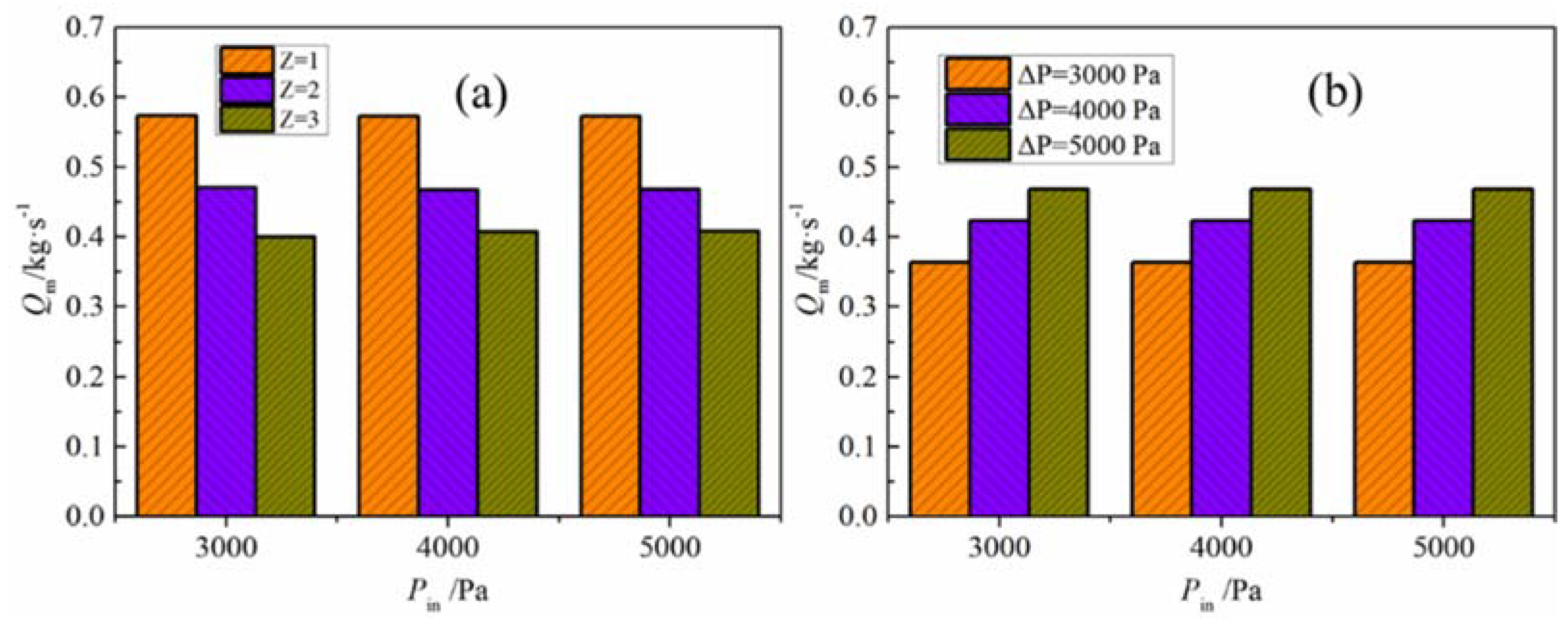
4.1. Effect of Pressure

As shown in Figure 5, the inlet pressure has little effect on the amount of direct leaked air in either different sealing number case or different pressure difference case. By contrast, the leakage amount gradually increases with the pressure difference. The leakage in the case of Δptot = 5 kPa is larger than that of Δptot = 4 kPa and Δptot = 3 kPa by 10.6% and 28.9%, respectively. In the process of direct air leakage, the pressure difference between air and flue gas is main cause of the leak. According to the Bernoulli equation, a portion of the pressure energy will be converted into kinetic energy during the airflow passing through the gap of the sealing sheets [24]. Thus, in our study, the pressure difference rather than the inlet pressure would be regarded as a factor affecting the direct leakage of the RAPH.

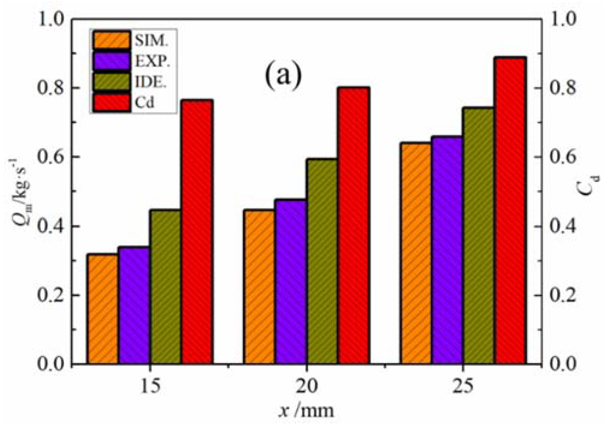
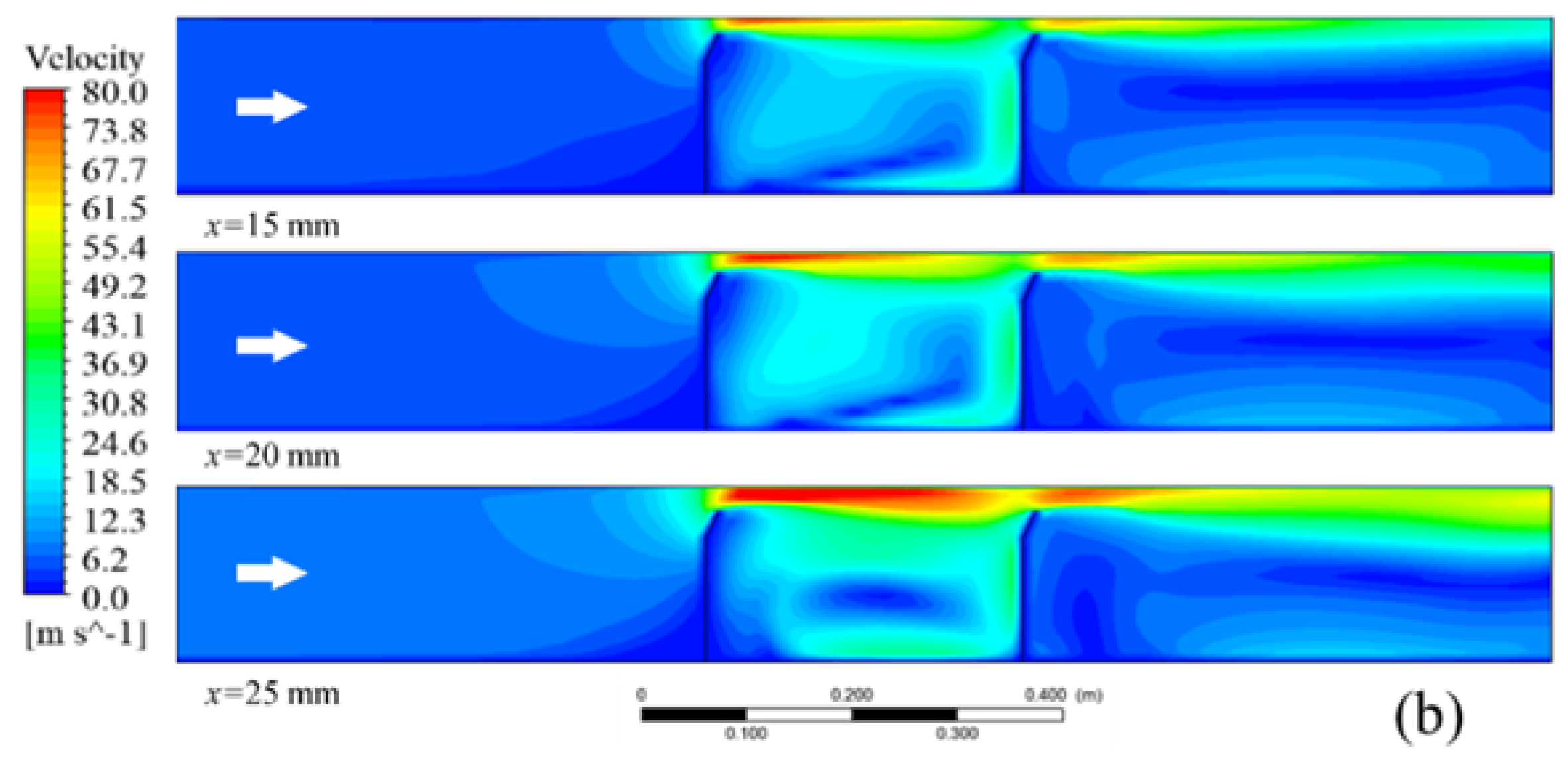
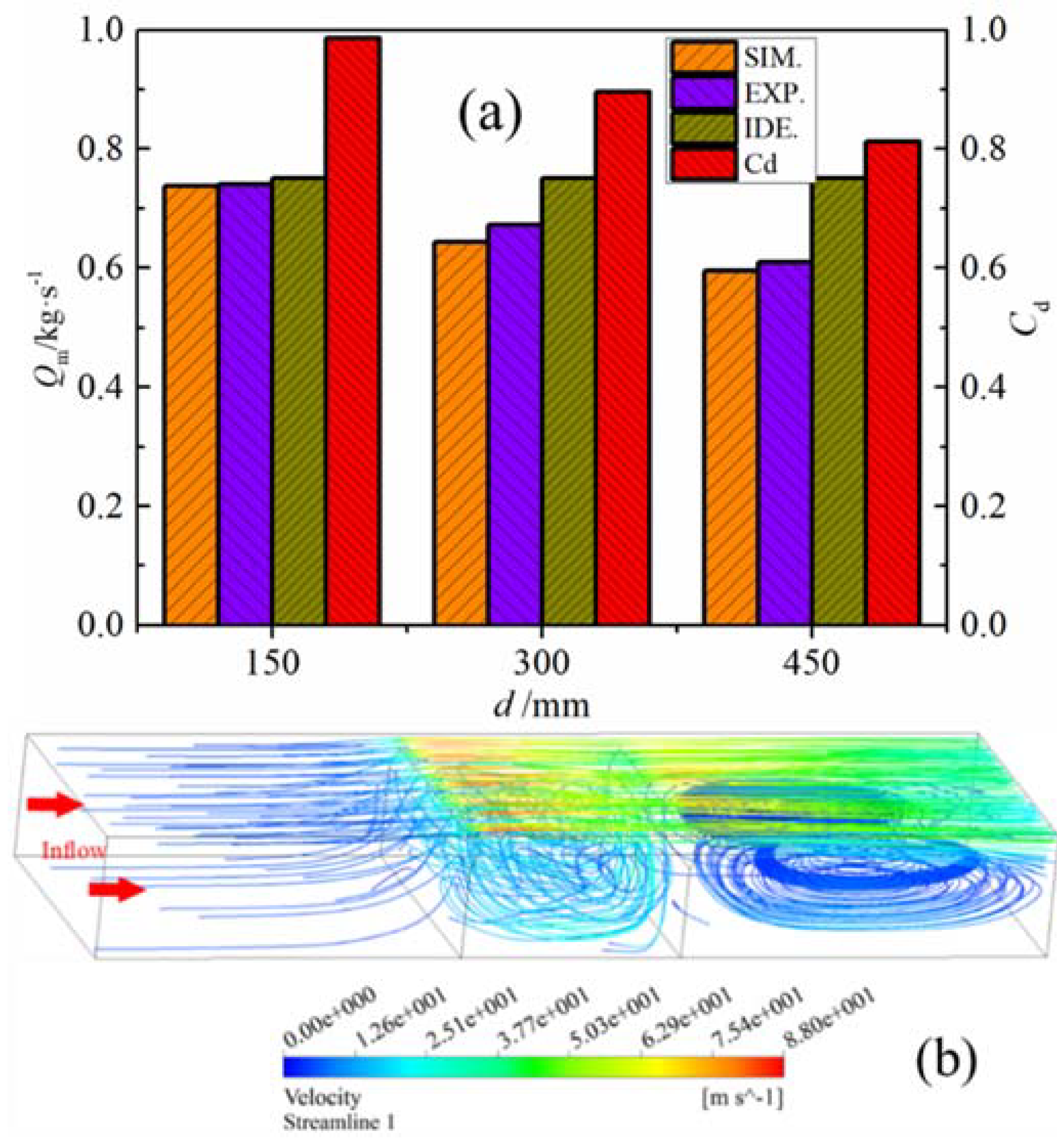
4.2. Effect of Sealing Gap

The effects of the gap size on leakage amount and orifice coefficient are shown in Figure 6a. The results were obtained under the condition that the spacing of 300 mm, the total pressure difference of 5 kPa, the sealing number of 2, and the bending angle of 25°. The abbreviation SIM, EXP, and IDE refer to the leakage results by simulation, experiment, and ideal gas calculation, respectively. The results show that both the leakage amount and the orifice coefficient increase with the leakage gap size. In the operation of RAPH, thermal stress deformation of the rotor would cause an increase in the gap size and lead to a larger leakage rate. The installation of sealing sheet in the flow path facilitates the formation of throttling structure. The well-known continuum theory tells us that when the fluid flows through a gap, the flow area gets smaller and the velocity gets larger at the gap position [25]. In the front of gap, the flow is in a stable state, which means that the fluid particles are in a balanced state. At the gap position, the fluid particles are sped up and fluid velocity is larger than that of the position in the front of gap. It can be clearly seen from the velocity contours (Figure 6b) that the velocity at the gap of 25 mm is greater than that of 15 mm.

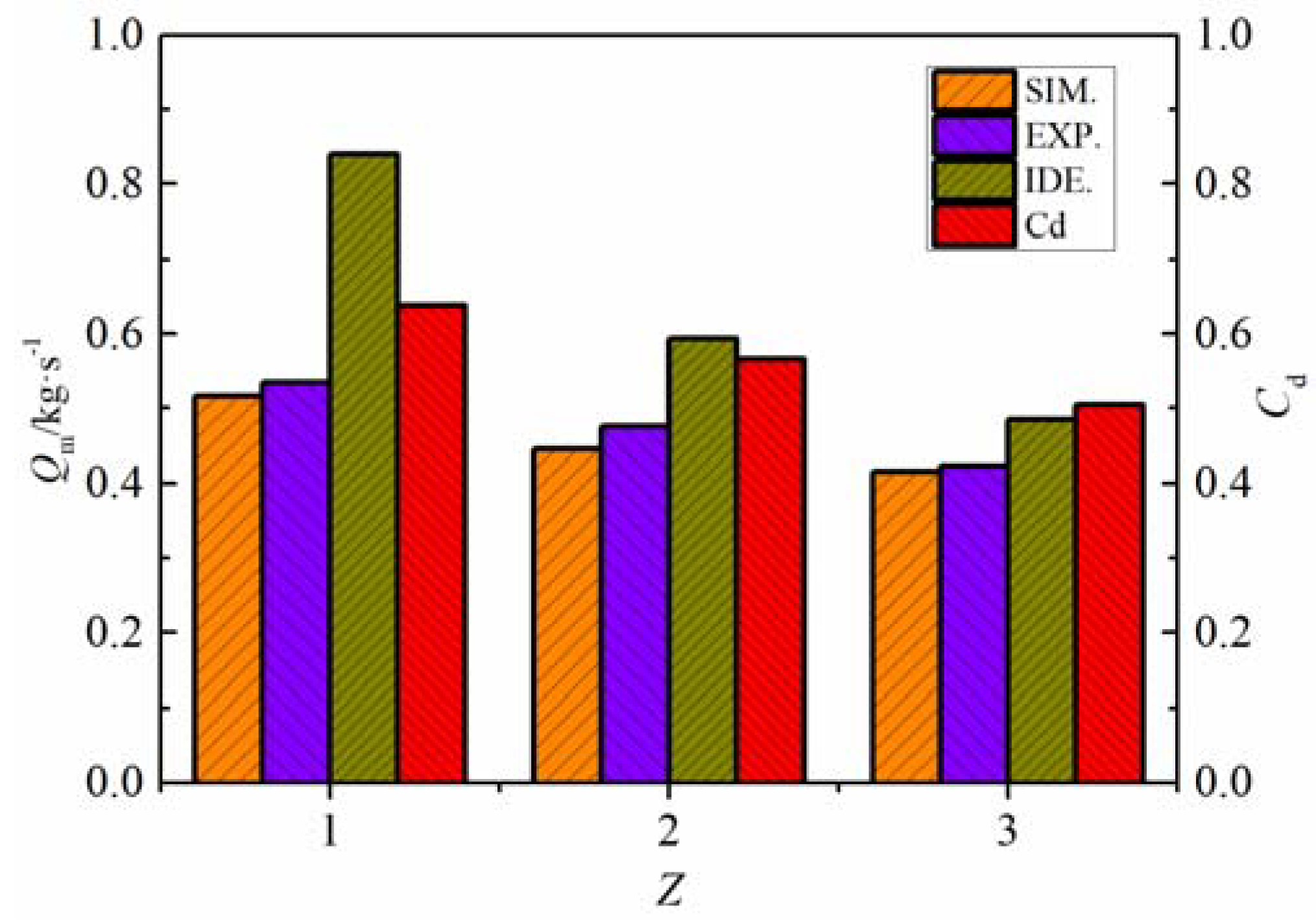
4.3. Effect of Sealing Sheets Number

Figure 7 shows the effect of the number of sealing sheets on air leakage under the condition that the spacing, the total pressure difference, the gap size, and the bending angle are 300 mm, 5 kPa, 20 mm, and −25°, respectively. Obviously, the effect of the number of sealing sheets can significantly influence the air leakage. Compared with the single-seal and double-seal cases, the tri-seal has the best sealing performance under the same total pressure difference Δptot. The leakage of tri-seal is less than that of the single and the double seals by 27.9% and 14.9%, respectively. Besides, the orifice coefficient would decrease with the increase in the number of sealing sheets. Therefore, the increase in the number of sealing sheets can reduce the leakage and enhance the sealing performance.
If there is no throttling device in the flow path, the pressure drop is mainly caused by the viscosity and roughness of the inner wall surface of the flow path. In the boundary layer, there is a high velocity gradient perpendicular to the mainstream direction, and there is a high pressure gradient in the mainstream direction. The presence of the sealing sheets in the flow path can have a large disturbing effect on the incoming flow, vortexes will be generated in front and rear of the throttling device [26]. The theory of wall vortex generation indicates that the fluid particles on the wall surface cannot be linearly translated under viscous conditions, and they will rotate under the action of the shear force [27]. The mainstream energy would be continuously reduced by the vortexes which are generated by the viscous force [28].

4.4. Effect of the Spacing of Adjacent Sealing Sheets

As the relative position of the sealing sheets is determined by the arrangement of the radial segmental plates in the RAPH, the spacing between adjacent sealing sheets would gradually increase in the radial direction. Figure 8a shows the effect of the spacing on air leakage under the condition that the number, the total pressure difference, the gap size, and the bending angle are 2, 5 kPa, 25 mm, and −25°, respectively. According to the ideal calculation results, the spacing value does not affect the air leakage, whereas the air leakage and the orifice coefficient decrease dramatically with the spacing value. In Figure 8b, when fluid passes through a slit, part of the streamlines will curve under the velocity gradient perpendicular to the mainstream direction. The vortex in the flow boundary layer will also diffuse into the mainstream region under the action of a velocity gradient perpendicular to the mainstream direction. The loss of mainstream energy would be enlarged by the streamline curvature, the recirculation zone and vortexes [27]. The vortex converts the kinetic energy of the gas into other forms of energy, resulting in a reduction of the leakage amount.

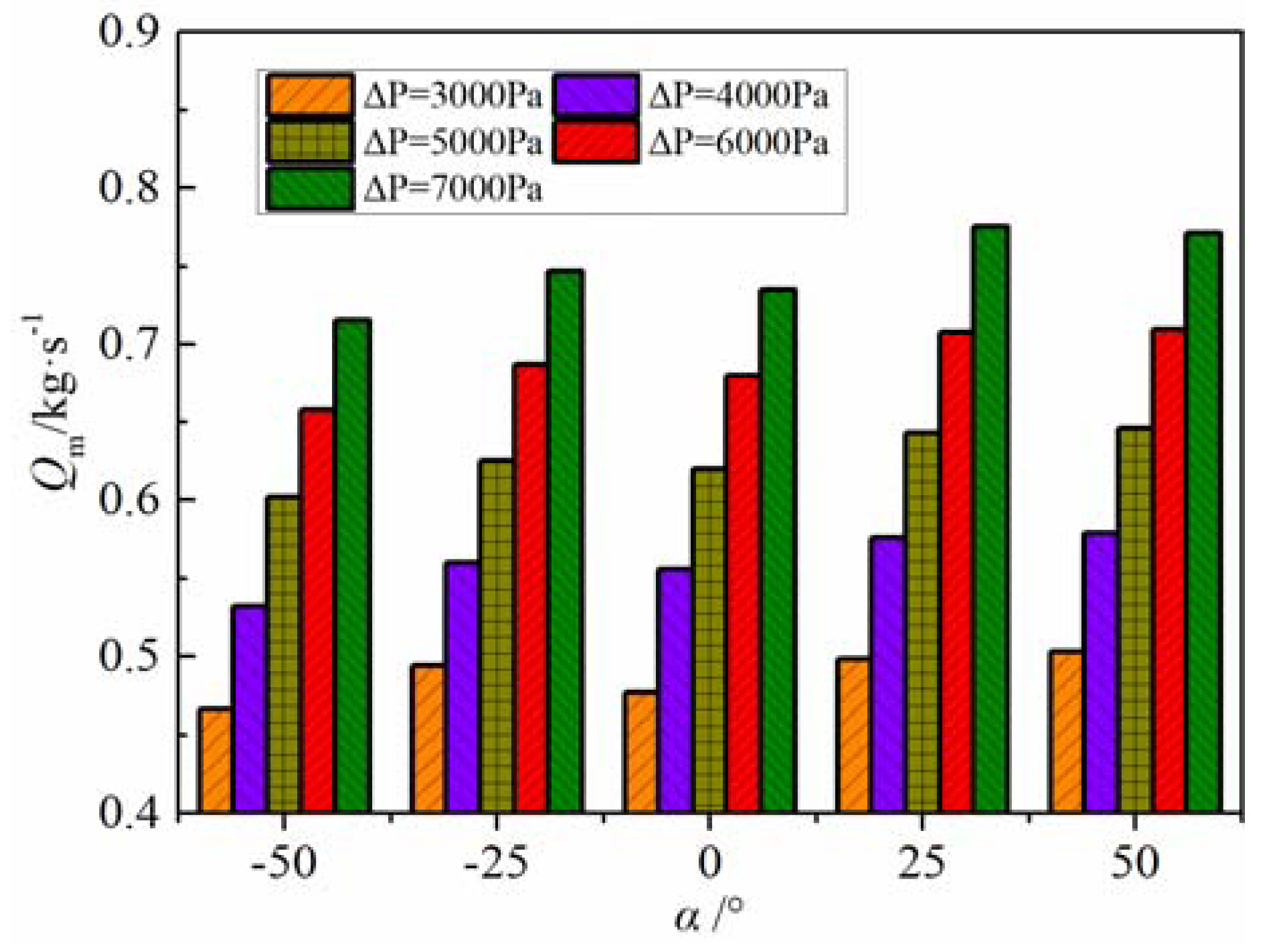
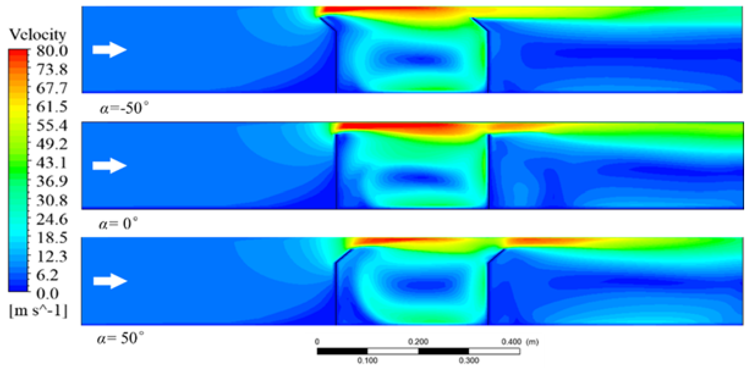
4.5. Effect of the Bending Angle of Sealing Sheets

The sealing sheet usually has a bending angle (Figure 2b) along the rotation direction of the rotor to prevent mechanical wear between the sealing sheets and the sector plate. Figure 9 shows the effects of different bending angle on the air leakage in different pressure difference cases. Obviously, the leakage amount at the negative bending angle is smaller than that at the positive bending angle. When the fluid flows to the second sealing sheet, a recirculation zone was formed between the sealing sheets under the action of the bending angle, where the energy of mainstream was dissipated and the leakage was reduced. For the tri-sectional RAPH, the direct radial leakage takes place at two locations. One is the interface between the primary air and the flue gas section and the other is the interface between the secondary air and flue gas. The leakage at the former location should be handled first, because the higher primary air pressure can cause more serious leakage problem. Therefore, it is recommended for the rotor of tri-sectional air preheater to pass through flue gas section, secondary air section, and primary air section in sequence. In addition, with the pressure difference increasing, the inertial force gradually becomes much larger than the viscous force. As a result, the air leakage gradually increases.
Figure 10 shows the contours of velocity at different bending angles. The bending angle has great effect on the distribution of flow field and the generation of recirculation zone, resulting in the difference of leakage. In the positive bending angle case, the streamlined structure cause less energy loss. By contrast, the sheets with negative bending angel would generate a local recirculation zone in front of the sealing sheet, resulting in greater resistance.

4.6. Correlation for Orifice Coefficient

Engineers usually pay more attention to the correlation between the orifice coefficient and the geometrical and operational parameters in application. Though the orifice coefficient was usually expressed as the function of Reynolds number [26], which is not easy to obtain in the leakage process of RAPH, a dimensionless correlation was proposed to evaluate effects of the gap size, seal sheets number, spacing of adjacent sealing sheets, and the total pressure difference on the orifice coefficient.
C d = ( x h 2 ) A ( Δ p t o t p 0 ) B ( Z ) C ( d W ) D
where p0 (101.325 kPa) is the ambient pressure; h2 (150 mm) and W (400 mm) are the height and weight of the seal sheet, respectively; and the power values of A, B, C, and D are assumed constant. These values were determined by using nonlinear fitting according to the data obtained. Table 2 presents the power values in Equation (7) for the most common cases of α = ±25° in application, which would provide theoretical reference for the design and improvement of seal system in the rotary regenerative air preheater.

5. Uncertainty Analysis

As the experimental data were obtained in such a non-universal setup in somewhere experiment operated, the uncertainty analysis can be of great significance in each part of the measurements. The uncertainty analysis can offer an effective way for the people who will read the work credibly to judge if the information presented is helpful. Also, the analysis of the experimental data is a crucial method to valid the measurement. Moffat [29] has proposed an uncertainty analysis method, the overall uncertainty can be expressed as a function of individual terms need to be measured in the experiment. The individual terms are generally combined by a root-sum-square method, which is expressed as the following equation,
δ Q m = { i = 1 N ( Q X i δ X i ) 2 } 1 / 2
where the partial derivative of Qm with respect to Xi is the sensitivity and the term δXi is the uncertainty of variable Xi.
In our experiment, the variables gap size x, the pressure p, and the air temperature T are directly measured. The uncertainty of response parameter mass flow rate Qm can be expressed as a function of aforementioned variables. The accuracy of tape, pressure gauge, and thermocouple are 0.001 m, 10 Pa, and 0.1 °C, respectively, based on which the maximum uncertainties of fluid density ρ (the effect of pressure on ρ is neglected) and mass flow rate Qm are 0.03% and 5.8%, respectively. Table 3 shows the measured parameter, the used devices and its range, accuracy and the corresponding uncertainty.

6. Conclusions

In this study, the effects of the gap size, spacing between the adjacent sealing sheets, sealing number, bending angle of sealing sheets, and pressure difference on direct air leakage and orifice coefficient are experimentally and numerically studied. The numerical results using the Transition k-kl-ω turbulence model are in good agreement with experimental data.
The flow resistance decreases with the gap size, which leads to an increase in direct leakage. The sealing performance is enhanced by increasing the spacing of adjacent sealing sheets. The sealing sheets with positive bending angle have less air resistance in the flow path, which would lead to larger leakage. The increase in the number of sealing sheets gives rise to an increase in the generation probability of recirculation zone and vortex, which aggravates the mainstream energy loss.
To obtain lower leakage rate, it is recommended for the tri-sectional air preheater that the rotor passes through flue gas section, secondary air section, and primary air section in sequence.
As listed in Table 2, we can rank all parameters base on its absolute value. Thus, the pressure difference has a dominant position, the next are the number of sealing sheets and the spacing of adjacent sealing sheets, the last is the gap size. Here, we do not consider the importance of bending angle, which remains to be further studied.

Author Contributions

Conceptualization, H.Z. and H.P.; data curation, D.L. and Y.H.; formal analysis, D.L.; funding acquisition, L.W.; investigation, D.L. and Y.H.; methodology, D.L., L.W., Y.H., and Y.B.; project administration, L.W.; resources, H.Z. and H.P.; supervision, D.C.; writing—original draft, H.Z.; writing—review and editing, D.L. All authors have read and agreed to the published version of the manuscript.

Funding

This research was funded by the Fundamental Research Funds for the Central University, grant number XJJ2018071; China Postdoctoral Science Foundation, grant number 2019M653625; and National Natural Science Foundation of China, grant number 51806171.

Acknowledgments

The authors would like to thank the State Key Laboratory of Multiphase Flow in Power Engineering for offering the centrifugal fan, and thank Zhang for his conscientious help and works.

Conflicts of Interest

The authors declare no conflicts of interest.

Appendix A

avan der Waals constant
Aleakage area, (m2)
bvan der Waals constant
Cdorifice coefficient
dspacing of adjacent sealing sheets, (mm)
h1straight height of sealing sheet, (mm)
h2total height of sealing sheet, (mm)
Hheight of flow path, (mm)
Llength of flow path, (mm)
Qmmass flow rate, (kg·s−1)
Qexpmass flow rate of experimental measurement, (kg·s−1)
Qidemass flow rate of ideal gas, (kg·s−1)
ppressure, (Pa)
pininlet pressure of flow path, (Pa)
Δppressure difference, (kPa)
Δptottotal pressure difference, (kPa)
Rmolar gas constant, (J·K−1·mol−1)
Tfluid temperature, (K)
Ufluid velocity, (m·s−1)
Vmmolar volume of the actual gas, (m3·mol−1)
Wwidth of flow path, (mm)
xgap size, (mm)
Znumber of sealing sheet
Greek symbols
αbending angle of sealing sheet, (°)
λthermal conductivity energy dissipation, (W·m−1·K−1)
ρfluid density, (kg·m−3)
υkinematic viscosity, (m2·s−1)
Φdissipation function
Subscripts
d discharge
tot total
exp experiment
ide ideal

References

  1. Bp Energy. Bp Energy Outlook—2019 Editionn; British Petroleum: London, UK, 2019. [Google Scholar]
  2. Warren, I. Ljungstrom Heat Exchangers for Waste Heat Recovery. J. Heat Recovery Syst. 1982, 2, 257–271. [Google Scholar] [CrossRef]
  3. Wang, H.Y.; Zhao, L.L.; Zhou, Q.T.; Xu, Z.G.; Kim, H.T. Exergy Analysis on the Irreversibility of Rotary Air Preheater in Thermal Power Plant. Energy 2008, 33, 647–656. [Google Scholar] [CrossRef]
  4. Wang, H.Y.; Zhao, L.L.; Xu, Z.G.; Chun, W.G.; Kim, H.T. The Study on Heat Transfer Model of Tri-Sectional Rotary Air Preheater Based on the Semi-Analytical Method. Appl. Therm. Eng. 2008, 28, 1882–1888. [Google Scholar] [CrossRef]
  5. Drobnič, B.; Oman, J.; Tuma, M. A Numerical Model for the Analyses of Heat Transfer and Leakages in a Rotary Air Preheater. Int. J. Heat Mass Transf. 2006, 49, 5001–5009. [Google Scholar] [CrossRef]
  6. Skiepko, T. Effect of Reduction in Seal Clearances on Leakages in a Rotary Heat Exchanger. Heat Recovery Syst. Chp 1989, 9, 553–559. [Google Scholar] [CrossRef]
  7. Skiepko, T. Experimental Results Concerning Seal Clearances in Some Rotary Heat Exchangers. Heat Recovery Syst. Chp 1988, 8, 577–581. [Google Scholar] [CrossRef]
  8. Lidia, F.; Claudio, Z.; Valerio, M. Aerodynamic Study for Air to Gas Leakage Reduction in a Typical Rotary Regenerative Air Preheater of Coal-Fired Steam Generators. Infect. Immun. 2010, 68, 994–998. [Google Scholar]
  9. Wang, H.Y.; Bi, X.L.; Zhao, L.L.; Zhou, Q.T.; Kim, H.T.; Xu, Z.G. A Study on Thermal Stress Deformation Using Analytical Methods Based on the Temperature Distribution of Storage Material in a Rotary Air-Preheater. Appl. Therm. Eng. 2009, 29, 2350–2357. [Google Scholar] [CrossRef]
  10. Wang, H.Y.; Zhao, L.L.; Xu, Z.G.; Chun, W.G.; Kim, H.T. Analysis on thermal stress deformation of rotary air-preheater in a thermal power plant. Korea J. Chem. Eng. 2009, 26, 833–839. [Google Scholar] [CrossRef]
  11. Wang, L.; Deng, L.; Tang, C.; Fan, Q.; Wang, C.; Che, D. Thermal Deformation Prediction Based on the Temperature Distribution of the Rotor in Rotary Air-Preheater. Appl. Therm. Eng. 2015, 90, 478–488. [Google Scholar] [CrossRef]
  12. Bu, Y.; Wang, L.; Chen, X.; Wei, X.; Deng, L.; Che, D. Numerical Analysis of Abs Deposition and Corrosion on a Rotary Air Preheater. Appl. Therm. Eng. 2018, 131, 669–677. [Google Scholar] [CrossRef]
  13. Cai, M.; Wang, X.; Zhao, S.; He, S. A Study on the Direct Leakage of Rotary Air Preheater with Multiple Seals. Appl. Therm. Eng 2013, 59, 576–586. [Google Scholar] [CrossRef]
  14. Faris, G.J. Clearance Monitoring Probe for Rotary Regenerative Heat Exchanger. U.S. Patent No. 3,968,569, 13 July 1976. [Google Scholar]
  15. Skiepko, T. Method of Monitoring and Measuring Seal Clearances in a Rotary Heat Exchanger. Heat Recovery Syst. Chp 1988, 8, 469–473. [Google Scholar] [CrossRef]
  16. Skiepko, T. Indirect Estimation of Leakage Distribution in Steam Boiler Rotary Regenerators. Heat Transf. Eng. 1997, 18, 56–81. [Google Scholar] [CrossRef]
  17. Skiepko, T. Some Essential Principles for Adjustment of Seal Clearances in Rotary Regenerators. Heat Transf. Eng. 2007, 14, 27–43. [Google Scholar] [CrossRef]
  18. Skiepko, T.; Shah, R.K. Modeling and Effect of Leakages on Heat Transfer Performance of Fixed Matrix Regenerators. Int. J. Heat Mass Transf. 2005, 48, 1608–1632. [Google Scholar] [CrossRef]
  19. Maharaj, A.; Schmitz, W.; Naidoo, R.; Jestin, L.; Fuls, W.; Pronobis, M. A Numerical Study of Air Preheater Leakage. Energy 2015, 92, 87–99. [Google Scholar] [CrossRef]
  20. Zhang, X.; Yuan, J.; Tian, Z.; Wang, J. Estimation of the Direct Leakage of Rotary Air Preheaters Based on Temperature Distribution Modeling. Int. J. Heat Mass Transf. 2019, 134, 119–130. [Google Scholar] [CrossRef]
  21. Du, X.; Shi, Y.; Wang, X. Coupled Characterization and Experimental Verification of Heat Transfer and Air Leakage in a Quad-Sectional Rotary Air Preheater. Appl. Therm. Eng. 2019, 159, 113923. [Google Scholar] [CrossRef]
  22. Jianqiang, G.; Shufang, T.; Xianling, L.; Zhifu, H. Influence of Air Leakage of Different Parts of the Air Preheater to Boiler Efficiency. Electr. Power Sci. Eng. 2011, 6, TK227. [Google Scholar]
  23. Kožíšek, M.; Příhoda, J.; Fürst, J.; Straka, P. Numerical Simulation of Transitional Flows with Heat Transfer. AIP Conf. Proc. 2016, 1745, 020029. [Google Scholar]
  24. Betchelor, G.K. An Introduction to Fluid Dynamics; Cambridge University Press: Cambridge, UK, 1994. [Google Scholar]
  25. Shen, W.; Tong, J. Engineering Thermodynamics, 5th ed.; High Education Press: Beijing, China, 2015. (In Chinese) [Google Scholar]
  26. Wu, D.; Burton, R.; Schoenau, G. An Empirical Discharge Coefficient Model for Orifice Flow. Int. J. Fluid Power 2002, 3, 13–19. [Google Scholar] [CrossRef]
  27. Hunt, J.C.R.; Vassilicos, J.C. Turbulence Structure and Vortex Dynamics; Cambridge University Press: Cambridge, UK, 2010. [Google Scholar]
  28. Zhang, Z.; Dong, Z. Viscous Fluid Mechanics; Tsinghua University Press: Beijing, China, 2011. (In Chinese) [Google Scholar]
  29. Moffat, R.J. Describing the Uncertainties in Experimental Results. Exp. Therm. Fluid Sci. 1988, 1, 3–17. [Google Scholar] [CrossRef] [Green Version]
Figure 1. Sketch of (a) general leakage paths in the rotary air preheater (RAPH) and (b) tri-seal sealing system.
Applsci 10 01523 g001
Figure 2. Sketch of (a) direct air leakage test system: (b) test section and (c) real sealing sheet.
Applsci 10 01523 g002
Figure 3. Mesh management: (a) mesh generation, (b) local mesh refine, and (c) mesh-independent verification.
Applsci 10 01523 g003aApplsci 10 01523 g003b
Figure 4. Comparison of simulation and experiment: Z = 2; d = 300 mm; x = 25 mm; Δptot= 4 kPa and α = 25°.
Applsci 10 01523 g004
Figure 5. Effect of inlet pressure on leakage in (a) different sealing number and in (b) different pressure difference.
Applsci 10 01523 g005
Figure 6. Effect of gap size: (a) numerical, experimental, and calculated results, and (b) contours of velocity.
Applsci 10 01523 g006aApplsci 10 01523 g006b
Figure 7. Effect of the number of sealing sheets on leakage.
Applsci 10 01523 g007
Figure 8. Sketch of (a) the effect of spacing of adjacent sealing sheets on direct leakage and (b) fluid streamline.
Applsci 10 01523 g008
Figure 9. Effect of different bending angle on leakage.
Applsci 10 01523 g009
Figure 10. Contours of velocity at different bending angles.
Applsci 10 01523 g010
Table 1. Conditions for experiments.
Descriptionx/mmΔptot/kPaZd/mmα
Value range15~253~71~3150~450−50~50
Table 2. Power values for the correlation at different restrictions.
αABCDR2
25°0.172340.002380.0914−0.23960.924
−25°0.205010.01240.14665−0.24520.951
Table 3. The main parts for the uncertainty analysis.
ParameterDevice UsedDevice RangeDevice AccuracyUncertainty
Gap sizeTape0–5 m±0.001 m0.02%
Static pressurePressure gauge0–99,990 Pa±10 Pa0.01%
Air temperatureThermocouple-50–150 °C±0.1 °C0.05%

