Monolitic Hybrid Transmitter-Receiver Lens for Rotary On-Axis Communications

 ,
,
Abstract
:
1. Introduction
2. Materials and Methods
2.1. Fundamental Concepts
2.1.1. Channel Model
2.1.2. Ideal Arrangement
2.1.3. Geometrical Arrangements
2.2. Hybrid Lens
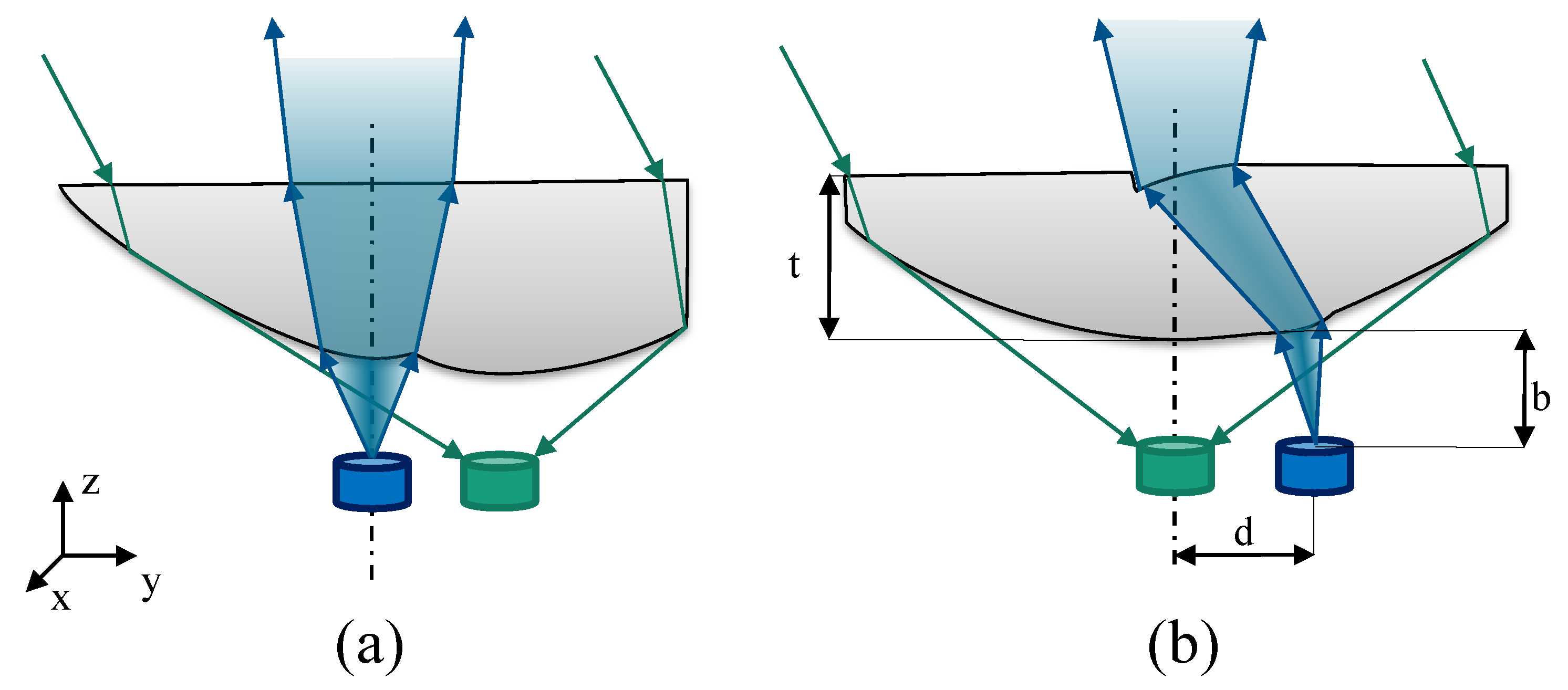
2.2.1. Concept
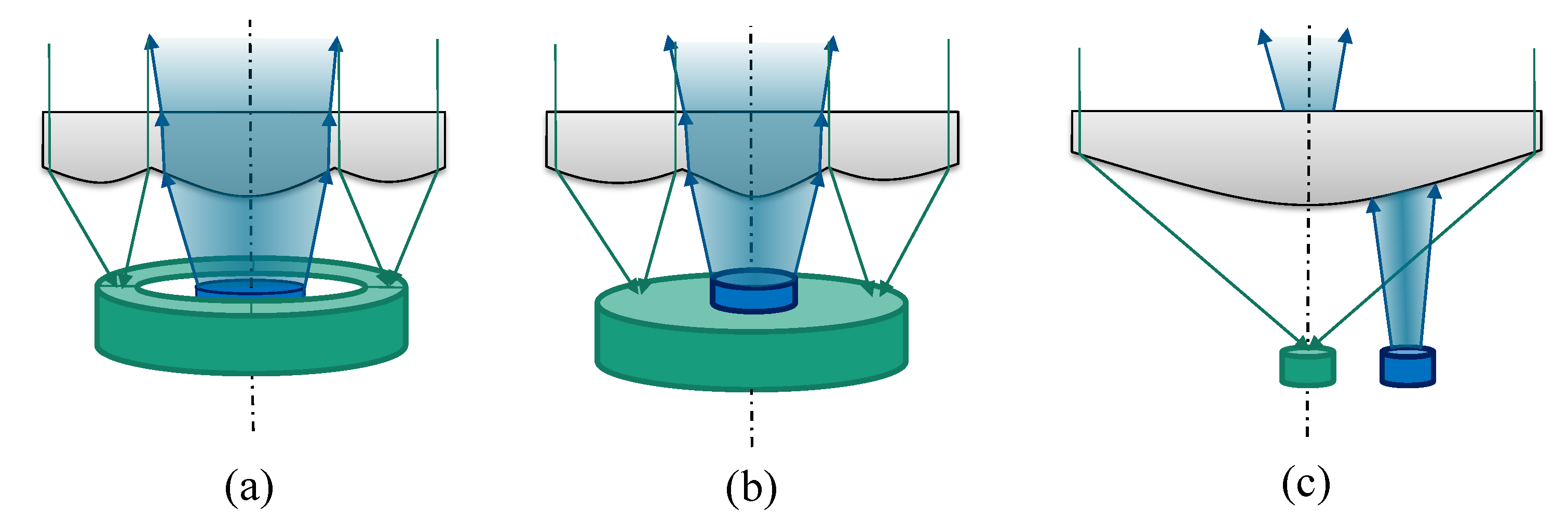
- The emitter is placed centrally and the PD is positioned off-axis as depicted in Figure 4a. In this case only the emission profile of the emitter has to be adjusted. This includes the homogenization of the profile and an adjustment of the angle . This can ideally be achieved with a single freeform interface. Therefore, the lower surface can be used for beam shaping and the top surface can be flat. The downside of this approach is a challenging RX lens design: the focus point of the RX lens part is off-axis.
- The PD is placed centrally and the emitter is positioned off-axis as shown in Figure 4b. The TX lens part fulfills two tasks: first, it compensates the displacement of the ray bundle regarding the optical axis. Second, it reshapes the ray bundle to the anticipated FOV. Because two surfaces are required, the top aperture of the lens cannot be flat. On the other hand, the design of the RX lens part is simplified, because the focal point is on the optical axis. If the TX part is neglected, the RX lens can be designed to be rotationally symmetrical. However, the shadowing effect of the TX part introduces a nonrotationally symmetric factor. Theoretically, this can be partly compensated by a nonrotationally symmetric RX lens part. The shadowing effect is also mitigated by minimizing the size of TX.
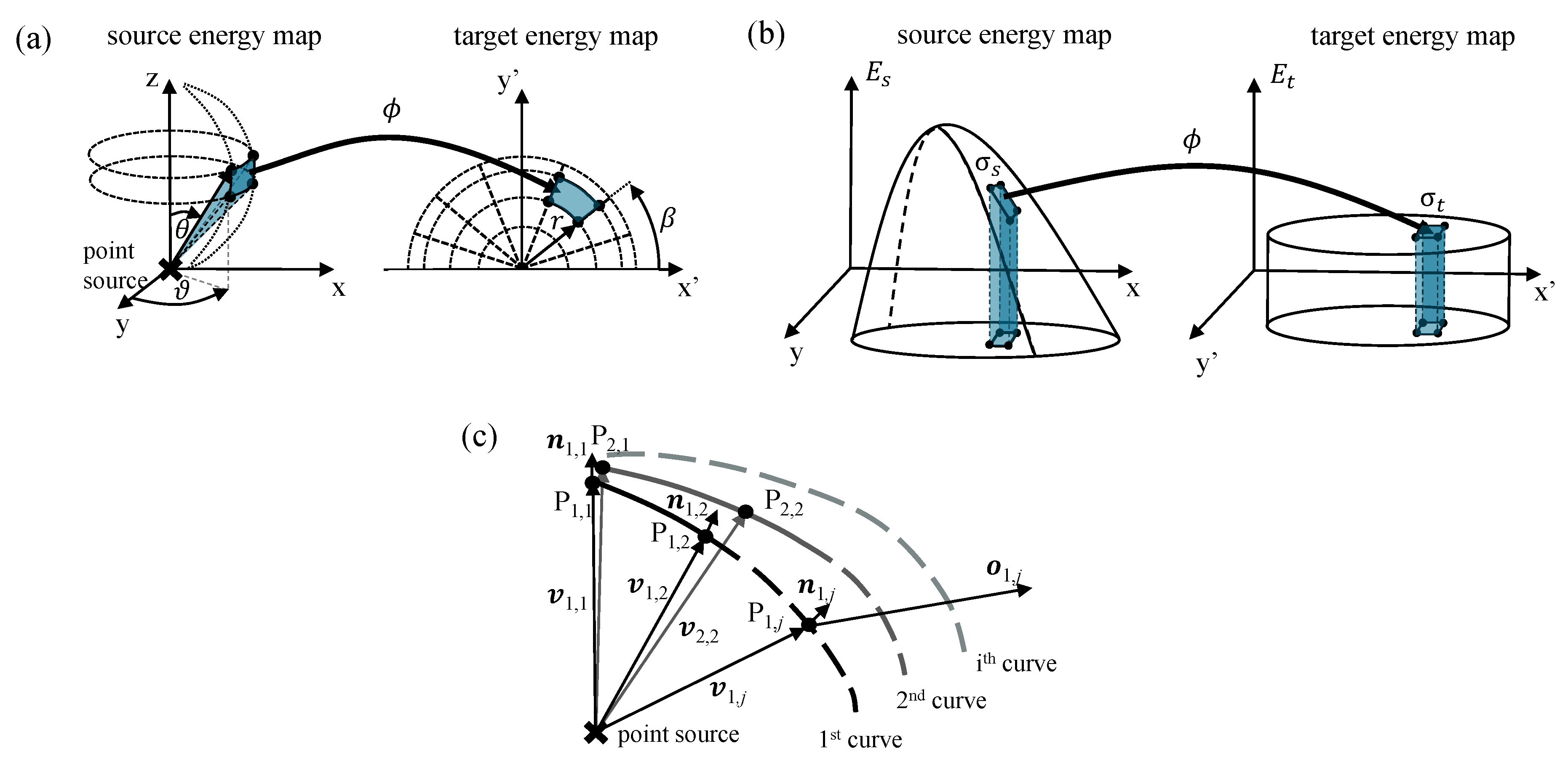
2.2.2. Optic Design Methods
2.3. System with Separated TX and RX
2.4. Simulation Parameters
3. Results
3.1. TX Performance
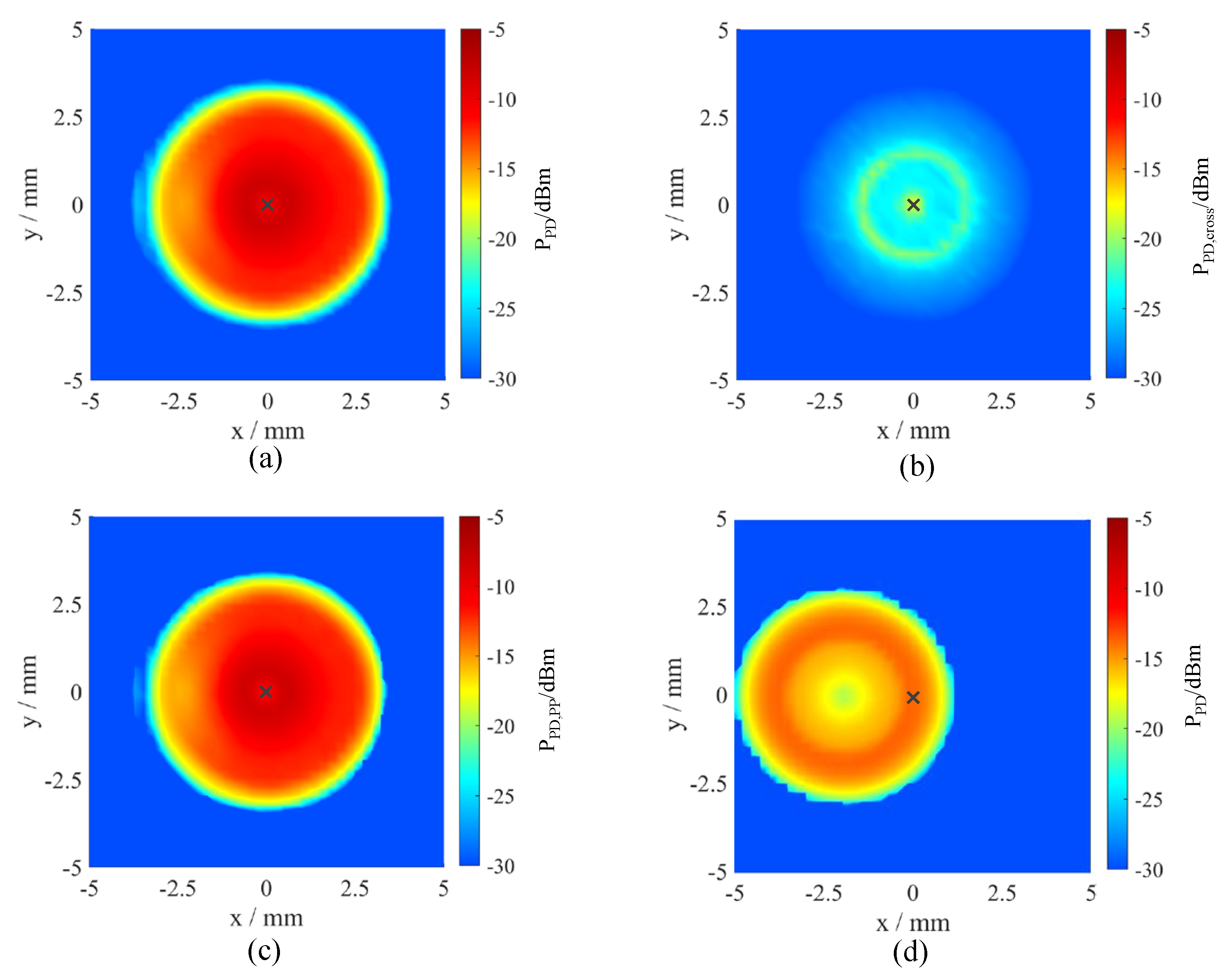
3.2. Full-Channel Performance
4. Discussion
4.1. TX Performance
4.2. Full-Channel Performance
4.3. Suitability for Rotary Scenarios
5. Conclusions
6. Patents
Author Contributions
Funding
Conflicts of Interest
Abbreviations
| BER | bit error rate |
| BW | bandwidth |
| EM | emitter |
| FORJ | fiber optic rotary joint |
| FOV | field of view |
| H TX-RX | hybrid transmitter-receiver lens system |
| LED | light emitting diode |
| LD | laser diode |
| NURBS | nonuniform rational B-splines |
| OWC | optical wireless communications |
| PD | photodetector |
| RF | radio frequency |
| S TX-RX | separate transmitter-receiver lens system |
| SNR | signal-to-noise ratio |
| RX | receiver |
| TIR | total internal reflection |
| TX | transmitter |
References
- Astier, R.; Capitaine, T.; Bourny, V.; Dubois, J.; Fortin, J. Technological leap of signal transfer system: CONTACTLESS. In Proceedings of the 38th Annual Conference on IEEE Industrial Electronics Society (IECON), Montreal, QC, Canada, 25–28 October 2012; pp. 3238–3243. [Google Scholar]
- Hong, E.; Gregory, D.A.; Krishnamurthy, A. Opto-electronics based wireless slip ring system. J. Eng. Comput. Arch. 2007, 1, 1–6. [Google Scholar]
- Wang, Z.; Gu, H.; Sun, P. Contactless signal transmission for industrial bus at rotary joint. In Proceedings of the 2015 IEEE International Conference on Signal Processing, Communications and Computing (ICSPCC), Ningbo, China, 19–22 September 2015; pp. 1–6. [Google Scholar]
- Ghelfi, P.; Laghezza, F.; Scotti, F.; Serafino, G.; Pinna, S.; Onori, D.; Lazzeri, E.; Bogoni, A. Photonics in Radar Systems: RF Integration for State-of-the-Art Functionality. IEEE Microw. Mag. 2015, 16, 74–83. [Google Scholar] [CrossRef]
- Nickel, H.U.; Doleschel, A.; Schmid, M. Multichannel rotary joints for surveillance radars - State-of-the-art and future trends. In Proceedings of the 14th International Radar Symposium (IRS), Dresden, Germany, 19–21 June 2013; pp. 282–287. [Google Scholar]
- Nickel, H.U.; Zovo, J.; Schmid, M. Refining Radar Architectures: Multichannel Rotary Joints for Surveillance Radars. IEEE Microw. Mag. 2016, 17, 60–74. [Google Scholar] [CrossRef]
- Vollbracht, D.; Gekat, F.; Hilger, D.; Hille, M. Waveguide fibre optic rotary joint for antenna mounted radar receivers. In Proceedings of the 34th Conference on Radar Meteorology, Poster, Williamsburg, VA, USA, 5–9 October 2009. [Google Scholar]
- Mi, L.; Yao, S.-L.; Sun, C.-D.; Sun, B.; Zhang, H.-J. A single-channel fiber optic rotary joint on the basis Of TEC fiber collimators. In Proceedings of the International Conference on Optical Communications and Networks (ICOCN 2010), Nanjing, China, 24–27 October 2010; pp. 437–440. [Google Scholar]
- Roberts, G.; Hadfield, P.; Humphries, M.E.; Bauder, F.; Izquierdo, J.M.G. Design and evaluation of the power and data contactless transfer device. In Proceedings of the 1997 IEEE Aerospace Conference, Snowmass, Aspen, CO, USA, 10 Febuary 1996; Volume 3, pp. 523–533. [Google Scholar]
- Song, Y.; Wang, S.; Feng, Y. Stable and Secure Contactless Connectivity of Power and Data in Rotational Applications. In Proceedings of the 2018 IEEE Asia-Pacific Conference on Antennas and Propagation (APCAP), Auckland, New Zealand, 5–8 August 2018; pp. 401–402. [Google Scholar]
- Patyuchenko, A. 60 GHz Wireless Data Interconnect for Slip Ring Applications; Technical Report; Analog Devices, Inc.: Norwood, MA, USA, 2019. [Google Scholar]
- Timsit, R.S.; Antler, M. Tribology of Electronic Connectors: Contact Sliding Wear, Fretting, and Lubrication: 7.4. Lubrication. In Electrical Contacts: Principles and Applications; Slade, P.-G., Ed.; CRC Press: Boca Raton, FL, USA, 2014; pp. 481–506. [Google Scholar]
- Doleschel, A.; Lege, M. Contactless solutions for radar rotary joint systems. In Proceedings of the 16th International Radar Symposium (IRS), Dresden, Germany, 24–26 June 2015; pp. 451–456. [Google Scholar]
- Panhans, C.; Stolle, R. High Bandwidth Contactless Rotary Transmitter Design Optimized for Baseband Transmission. In Proceedings of the 11th International Conference on Information Technology and Electrical Engineering (ICITEE), Pattaya, Thailand, 10–11 October 2019; pp. 1–6. [Google Scholar]
- Wageningen, D.V.; Staring, T. The Qi wireless power standard. In Proceedings of the 14th International Power Electronics and Motion Control Conference (EPE-PEMC), Ohrid, Macedonia, 6–8 September 2010; pp. S15-25–S15-32. [Google Scholar]
- Dorsey, G.F.; Coleman, D.S.; Witherspoon, B.K. High Speed Data across Sliding Electrical Contacts. In Proceedings of the 2012 IEEE 58th Holm Conference on Electrical Contacts (Holm), Portland, OR, USA, 23–26 September 2012; pp. 1–12. [Google Scholar]
- Chen, H.; Hsu, S.; Chang, T.; Chi, W.; Ma, S.; Wu, T. Signal integrity design for GHz high-speed differential wires with slip ring capsule. In Proceedings of the 2012 IEEE International Symposium on Electromagnetic Compatibility, Pittsburgh, PA, USA, 6–10 August 2012; pp. 18–21. [Google Scholar]
- Slade, P.-G. Electrical Contacts: Principles and Applications; CRC Press: Boca Raton, FL, USA, 2014. [Google Scholar]
- Faulwaßer, M.; Kirrbach, R.; Schneider, T.; Noack, A. 10 Gbit/s bidirectional transceiver with monolithic optic for rotary connector replacements. In Proceedings of the 2018 Global LIFI Congress (GLC), Paris, France, 8–9 February 2018; pp. 95–102. [Google Scholar]
- Rappaport, T.S.; Sun, S.; Mayzus, R.; Zhao, H.; Azar, Y.; Wang, K.; Wong, G.N.; Schulz, J.K.; Samimi, M.; Gutierrez, F. Millimeter Wave Mobile Communications for 5G Cellular: It Will Work! IEEE Access 2013, 1, 335–349. [Google Scholar] [CrossRef]
- Aizawa, T.; Sakai, M.; Toguchi, S.; Hirohashi, K. Optical Slip Rings for Home Security High-Definition Cameras. In Proceedings of the 2007 Digest of Technical Papers International Conference on Consumer Electronics, Las Vegas, NV, USA, 10–14 January 2007; pp. 1–2. [Google Scholar]
- Guenter, J.K.; Hawthorne, R.A.; Granville, D.N.; Hibbs-Brenner, M.K.; Morgan, R.A. Reliability of proton-implanted VCSELs for data communications. In Proceedings of the SPIE 2683, Fabrication, Testing, and Reliability of Semiconductor Lasers, San Jose, CA, USA, 4 April 1996; pp. 102–113. [Google Scholar]
- Christou, A.; Unger, B.A. Semiconductor Device Reliability; Christou, A., Unger, B.A., Eds.; Springer: Dordrecht, The Netherlands, 1990; p. 60. [Google Scholar]
- Vinh, Q.T.; Khanh, T.Q.; Ganev, H.; Wagner, M. Measurement and Modeling of the LED Light Source. In LED Lighting: Technology and Perception, 1st ed.; Khanh, T.Q., Bodrogi, P., Vinh, Q.T., Winkler, H., Eds.; John Wiley & Sons, Ltd: Hoboken, NJ, USA, 2014; pp. 214–222. [Google Scholar]
- Dorsey, G.F. Fiber Optic Rotary Joints - A Review. IEEE Trans. Compon. Hybrids Manuf. Technol. 1982, 5, 37–41. [Google Scholar] [CrossRef]
- Säckinger, E. Analysis and Design of Transimpedance Amplifiers for Optical Receivers, 1st ed.; John Wiley and Sons: Hoboken, NJ, USA, 2018; pp. 46, 48, 56, 120–127, 197–199, 469–474. [Google Scholar]
- Safety of Laser Products - Part 1: Equipment Classification and Requirements; IEC 60825-1:2014; IEC: Geneva, Switzerland, 2014.
- Kirrbach, R.; Jakob, B.; Noack, A. Introducing Advanced Freeform Optic Design to Li-Fi Technology. In Proceedings of the 7th International Conference on Photonics, Optics and Laser Technology (PHOTOPTICS 2019), Prague, Czech Republic, 25–27 February 2019; pp. 249–250. [Google Scholar]
- Kahn, J.; Barry, J.R. Wireless Infrared Communications. Proc. IEEE 1997, 85, 265–298. [Google Scholar] [CrossRef] [Green Version]
- Welford, W.T.; Winston, R. High Collection Nonimaging Optics, 1st ed.; Academic Press Inc.: San Diego, CA, USA, 1989; pp. 1–28, 54. [Google Scholar]
- Kirrbach, R.; Faulwaßer, M.; Jakob, B. Non-rotationally Symmetric Freeform Fresnel-Lenses for Arbitrary Shaped Li-Fi Communication Channels. In Proceedings of the 2019 Global LIFI Congress (GLC), Paris, France, 12–13 June 2019; pp. 103–108. [Google Scholar]
- Stepniak, G.; Kowalczyk, M.; Maksymiuk, L.; Siuzdak, J. Transmission Beyond 100 Mbit/s Using LED Both as a Transmitter and Receiver. IEEE Photonics Technol. Lett. 2015, 27, 2067–2070. [Google Scholar] [CrossRef] [Green Version]
- Serial Infrared Transceiver (SIR), 115.2 kbit/s, 2.4 V to 5.5 V Operation TFBS4711, Vishay Semiconductors, rev. 3.3, 08.04.2019. Available online: http://www.vishay.com (accessed on 30 November 2019).
- Faulwaßer, M.; Deicke, F.; Schneider, T. 10 Gbit/s bidirectional optical wireless communication module for docking devices. In Proceedings of the 2014 IEEE Globecom Workshops (GC Wkshps), Austin, TX, USA, 8–12 December 2014; pp. 512–517. [Google Scholar]
- Manousiadis, P.; Rajbhandari, S.; Mulyawan, R.; Vithanage, D.; Chun, H.; Faulkner, G.; O’brien, D.; Turnbull, G.; Collins, S.; Samuel, I. Wide field-of-view fluorescent antenna for visible light communications beyond the étendue limit. Optica 2016, 3, 702–706. [Google Scholar] [CrossRef]
- Naumann, H.; Schröder, G.; Löffler-Mang, M. Handbuch Bauelemente der Optik: Grundlagen, Werkstoffe, Geräte, Messtechnik, 7th ed.; Carl Hanser Verlag: Munich Vienna, Germany, 2014; pp. 69–70, 81–83. [Google Scholar]
- Mäkinen, J.-K. Cost Modeling of Injection-Molded Plastic Optics. In OECC Handbook of Plastic Optics, 2nd ed.; Bäumer, S., Ed.; WILEY-VCH Verlag GmbH and Co. KGaA: Weinheim, Germany, 2010; p. 229. [Google Scholar]
- Miñano, J.C. SMS 3D Design Method. In Illumination Engineering: Design of Nonimaging Optics; Anderson, J., Ed.; Wiley-IEEE Press: Hoboken, NJ, USA, 2013; p. 102. [Google Scholar]
- Wang, K.; Liu, S.; Xiaobing, L.; Wu, D. Basic Algorithms of Freeform Optics for LED Lighting. In Freeform Optics for LED Packages and Applications, 1st ed.; John Wiley and Sons: Singapore, 2017; pp. 25–69. [Google Scholar]
- Ma, D. Exploration of Ray Mapping Methodology in Freeform Optics. Ph.D. Thesis, The University of Arizona, Tucson, AZ, USA, 2015. [Google Scholar]
- Bruneton, A.; Bäuerle, A.; Wester, R.; Stollenwerk, J.; Loosen, P. Limitations of the ray mapping approach in freeform optics design. Opt. Lett. 2013, 38, 1945–1947. [Google Scholar] [CrossRef]
- Desnijder, K.; Hanslaer, P.; Meuret, Y. Flexible design method for freeform lenses with an arbitrary lens contour. Opt. Lett. 2017, 42, 5238–5241. [Google Scholar] [CrossRef]
- Desnijder, K.; Hanslaer, P.; Meuret, Y. A ray mapping method for off-axis and non-paraxial freeform illumination lens design. Opt. Lett. 2019, 44, 771–774. [Google Scholar] [CrossRef] [PubMed]
- Desnijder, K.; Ryckaert, W.; Hanslaer, P.; Meuret, Y. Luminance spreading freeform lens arrays with accurate intensity control. Opt. Express 2019, 27, 32994–33004. [Google Scholar] [CrossRef] [PubMed]
- Wu, R.; Liu, P.; Zhang, Y.; Zheng, Z.; Li, H.; Liu, X. A mathematical model of the single freeform surface design for collimated beam shaping. Opt. Express 2013, 21, 20976–20989. [Google Scholar] [CrossRef] [PubMed]
- Wu, R.; Zhang, Y.; Sulman, M.M.; Zheng, Z.; Benítez, P.; Miñano, J.C. Initial design with L2 Monge-Kantorovich theory for the Monge–Ampère equation method in freeform surface illumination design. Opt. Express 2014, 22, 16161–16177. [Google Scholar] [CrossRef]
- Michaelis, D.; Schreiber, P.; Bräuer, A. Cartesian oval representation of freeform optics in illumination systems. Opt. Lett. 2011, 36, 918–920. [Google Scholar] [CrossRef]
- Winston, R.; Minano, J.C.; Benitez, P.G.; Shatz, N.; Bortz, J.C. Nonimaging Optics, 1st ed.; Academic Press: Burlington, MA, USA, 2005; pp. 181–218. [Google Scholar]
- Benitez, P.G.; Miñano, J.C.; Blen, J.; Arroyo, R.M.; Chaves, J.; Dross, O.; Hernandez, M.; Falicoff, W. Simultaneous multiple surface optical design method in three dimensions. Opt. Eng. 2004, 43, 1489–1502. [Google Scholar] [CrossRef]
- Ries, H.; Muschaweck, J. Tailored freeform optical surfaces. J. Opt. Soc. Am. 2002, 19, 590–595. [Google Scholar] [CrossRef]
- Wallhead, I.; Jiménez, T.M.; Ortiz, J.V.G.; Toledo, I.G.; Toledo, C.G. Design of an efficient Fresnel-type lens utilizing double total internal reflection for solar energy collection. Opt. Express 2010, 20, A1005–A1010. [Google Scholar] [CrossRef]
- Piegl, L.; Tiller, W.J. The NURBS Book, 2nd ed.; Springer: Berlin/Heidelberg, Germany, 1995. [Google Scholar]
- Ning, X.; Winston, R.; O’Gallagher, J. Dielectric totally internally reflecting concentrators. Appl. Opt. 1987, 26, 300–305. [Google Scholar] [CrossRef]
- Tzeng, L.D.; Mizuhzra, O.; Nguyen, T.V.; Ogawa, K.; Watanabe, I.; Makita, K.; Tsuji, M.; Taguchi, K. A high-sensitivity APD receiver for 10-Gb/s system applications. IEEE Photonics Technol. Lett. 1996, 8, 1229–1231. [Google Scholar] [CrossRef]
- Gomez, A.; Shi, K.; Quintana, C.; Maher, R.; Faulkner, G.; Bayvel, P.; Thomsen, B.C.; O’Brien, D. Design and Demonstration of a 400 Gb/s Indoor Optical Wireless Communications Link. J. Lightw. Technol. 2016, 34, 5332–5339. [Google Scholar] [CrossRef]
- Schneider, T. Optische Sende-/Empfangs-Einheit und Vorrichtung zur Signalübertragung. DE102018205559 B3, 12 April 2018. [Google Scholar]
- Schneider, T. Optical Transceiver Unit and Device for Signal. Transmission. Patent No. WO19197343A1, 8 April 2019. [Google Scholar]


| Group | Contact | Contactless | ||||
|---|---|---|---|---|---|---|
| Type | Slip Ring | Capacitive | RF | Fiber (FORJ) | OWC | |
| Single | Multi | |||||
| Ref. | [5,6,16,17,18] | [6,9,11,13] | [1,6,10,11,13] | [4,7,8] | [6,13] | [19] |
| data rate/ | ... 3 | ... | ...5 | 10...40 | * | |
| max speed / rpm | >1400 * | |||||
| max revolutions | > | > | > | > | > | |
| cost (initial) | medium | low/medium | low/medium | high | very high | low |
| cost (maintenance) | high | low | low | low | high | low |
| RF immunity | weak | medium | weak | strong | strong | strong |
| on-/off axis | off-axis | off-axis | off-axis | on-axis | on-axis | on-axis |
| Merit | Unit | LD | H TX-RX | S TX-RX |
|---|---|---|---|---|
| Emin | 14.6 | 117 | 25.9 | |
| % | ||||
| % | ||||
| % | ||||
| % | 0 | |||
| % |
| Misalignment/mm | −0 | −0.5 | −1 | −1.5 | −2 | −2.5 | −3 | −3.5 |
|---|---|---|---|---|---|---|---|---|
| H TX-RX: | ||||||||
| H TX-RX: | ||||||||
| H TX-RX: | ||||||||
| S TX-RX: | < | < | < | < | < |
© 2020 by the authors. Licensee MDPI, Basel, Switzerland. This article is an open access article distributed under the terms and conditions of the Creative Commons Attribution (CC BY) license (http://creativecommons.org/licenses/by/4.0/).
Share and Cite
Kirrbach, R.; Faulwaßer, M.; Schneider, T.; Meißner, P.; Noack, A.; Deicke, F. Monolitic Hybrid Transmitter-Receiver Lens for Rotary On-Axis Communications. Appl. Sci. 2020, 10, 1540. https://0-doi-org.brum.beds.ac.uk/10.3390/app10041540
Kirrbach R, Faulwaßer M, Schneider T, Meißner P, Noack A, Deicke F. Monolitic Hybrid Transmitter-Receiver Lens for Rotary On-Axis Communications. Applied Sciences. 2020; 10(4):1540. https://0-doi-org.brum.beds.ac.uk/10.3390/app10041540
Chicago/Turabian StyleKirrbach, René, Michael Faulwaßer, Tobias Schneider, Philipp Meißner, Alexander Noack, and Frank Deicke. 2020. "Monolitic Hybrid Transmitter-Receiver Lens for Rotary On-Axis Communications" Applied Sciences 10, no. 4: 1540. https://0-doi-org.brum.beds.ac.uk/10.3390/app10041540