Agustín de Betancourt’s Optical Telegraph: Geometric Modeling and Virtual Reconstruction


1
Department of Engineering Graphics, Design and Projects, University of Jaén, Campus de las Lagunillas, s/n, 23071 Jaén, Spain
2
Engineering Graphics and Industrial Archaeology Research Group, University of Jaén, Campus de las Lagunillas, s/n, 23071 Jaén, Spain
*
Author to whom correspondence should be addressed.
Appl. Sci. 2020, 10(5), 1857; https://0-doi-org.brum.beds.ac.uk/10.3390/app10051857
Submission received: 20 February 2020
/
Revised: 1 March 2020
/
Accepted: 3 March 2020
/
Published: 9 March 2020
(This article belongs to the Special Issue Applied Sciences to the Study of Technical Historical Heritage and/or Industrial Heritage)
Abstract
:This article shows the geometric modeling and virtual reconstruction of the optical telegraph by Agustín de Betancourt and Abraham Louis Breguet developed at the end of the 18th century. Autodesk Inventor Professional software has been used to obtain the three-dimensional (3D) model of this historical invention and its geometric documentation. The material for the research is available on the website of the Betancourt Project of the Canary Orotava Foundation for the History of Science. Thanks to the three-dimensional modeling performed, it has been possible to explain in detail both its operation and the assembly system of this invention in a coherent way. After carrying out its 3D modeling and functional analysis, it was discovered that the transmissions in the telegraph were not performed by hemp ropes but rather by metal chains with flat links, considerably reducing possible error. Similarly, it has also been found that the use of the gimbal joint facilitated the adaptability of the invention to geographical areas where there was a physical impediment to the alignment of telegraph stations. In addition, it was not now necessary for the telescope frames to be located parallel to the mast frame (frame of the indicator arrow) and therefore they could work in different planes.
1. Introduction
The present study is part of the research line of industrial archeology whose purpose is the systematic study of the industrial memory of an era. Addressing industrial archaeology from the point of view of engineering provides a necessary vision for the correct understanding of industrial heritage, since in many occasions this study is carried out in an unscientific way, the written record of said heritage being incomplete and with the consequent risk of loss.
The work presented in this article has been developed within a research project on the work of an outstanding Spanish Enlightenment engineer, Agustín de Betancourt [1,2], analyzing his best-known inventions from an engineering graphics standpoint in order to obtain his geometric modeling [3,4,5,6,7].
As is well known, a first step for the recovery and study of historical technical heritage is the creation of realistic three-dimensional (3D) models. The article shows the 3D digital restitution of Betancourt’s optical telegraph. This 3D model has been obtained using CAD (computer-aided design) techniques, following the objectives established in the document Principles of Seville [8] on virtual archeology which cites the London Charter [9] regarding the computer-based visualization of cultural heritage.
In 1791, the first telegraph using optical signals appeared in the work of the French Claude Chappe and his four brothers. It consisted of a dial similar to that of a watch with a moving hand that could adopt 16 positions, which each corresponded to a symbol. To indicate that the next telegraph station had received the message, it emitted an acoustic signal. However, the main drawback was in distinguishing precisely the exact position of the needle due to its size and the separation between symbols [10].
Subsequently, he developed an optical telegraph model based on five panels of the binary type (all or nothing) that assigned a code to each of the 32 possible combinations (25), but the results were not as expected.
Finally a third model was proposed which ignited the interest of the National Assembly of France and led to the Paris-Lille line coming into operation in 1794 along 230 km of telegraph line and 22 towers, the last one located in the dome of the Louvre, transmitting the first telegram in history [11]. Construction of the mechanisms that moved the telegraph relied on the knowledge of the Swiss watchmaker Abraham Louis Breguet, so the optical telegraph would come to be called Chappe–Breguet. The system was quite effective, although it faced the limitation that visibility between stations was not always optimal, a situation which caused numerous errors in transmission.
Simultaneously, Chappe’s technological advances were widespread in numerous countries in Europe and the United States. Thus, in Sweden in 1794 Abraham Edelcrantz developed another type of telegraph that consisted of a system of 10 screens that could rotate 90º to be ‘seen’ or ‘not seen’. Thus, the different positions of the screens formed combinations of numbers that were translated into letters, words or phrases through code books.
In the same year, 1794, the Englishman George Murray developed another telegraph, inspired by that of Edelcrantz, which consisted of six screens arranged around two columns, being able to form up to 64 possible combinations (26) to transmit messages [10].
In Spain the figure of the engineer Agustín de Betancourt stood out and during his stay in Paris he met Abraham Louis Breguet, with whom he could analyze in detail Chappe’s telegraph. Between 1793 and 1796, Betancourt also traveled to London where he delved into Murray’s telegraphic model. These visits allowed him to develop his own optical telegraph model [12], which improved on Chappe’s telegraph in certain aspects.
Moreover, on 17 February 1799 King Carlos IV approved a project for the implementation of the optical telegraph in Spain, and in 1800 the first telegraph line that connected Madrid with Aranjuez began operating. However, the economic crisis that the country was going through did not allow Betancourt’s invention to thrive [13].
After a review of the state of the art of the technical studies related to the Betancourt optical telegraph, only a single and interesting mechanical study has been found in the case that the telegraph stations are not aligned [14]. However, there is no study from the point of view of engineering graphics, that allows the reader to understand perfectly and in detail the operation of this historical invention that marked a milestone in the field of telecommunications. The main objective of this research is to obtain a reliable 3D CAD model of this historical invention that allows us to know in detail this outstanding engineering work. The originality and novelty of this research is that there is no existing 3D CAD model of this historical invention with this degree of detail, so it will help in an outstanding way in the detailed understanding of its operation. An educational goal is also pursued, through its exhibition on the websites of the foundations that have supported this research (Fundación Canaria Orotava de Historia de la Ciencia [15] and Fundación Agustín de Betancourt [16]), as well as in other museums of the history of technology. On the other hand, the impact of this research depends on its future uses. Among these, we can highlight:
- Performing a static analysis with CAE (computer-aided engineering) techniques in order to determine whether the invention was well dimensioned and supported the demands of its operation.
- Developing applications of virtual reality and augmented reality to promote the interaction of the user with the model that will help them to better understand its operation and appreciate for each element or system its denomination and the materials from which it was manufactured.
- Incorporating WebGL models into a website.
- Printing in 3D using additive manufacturing together with an animation created by a photorealistic organizer for its exhibition in a museum, interpretation center, or foundation.
The remainder of the paper is structured as follows: Section 2 presents the materials and methods used in this investigation. Section 3 includes the main results of the process of geometric modeling and discussion of them in order to explain the operation of this device, and Section 4 states the main conclusions.
2. Materials and Methods
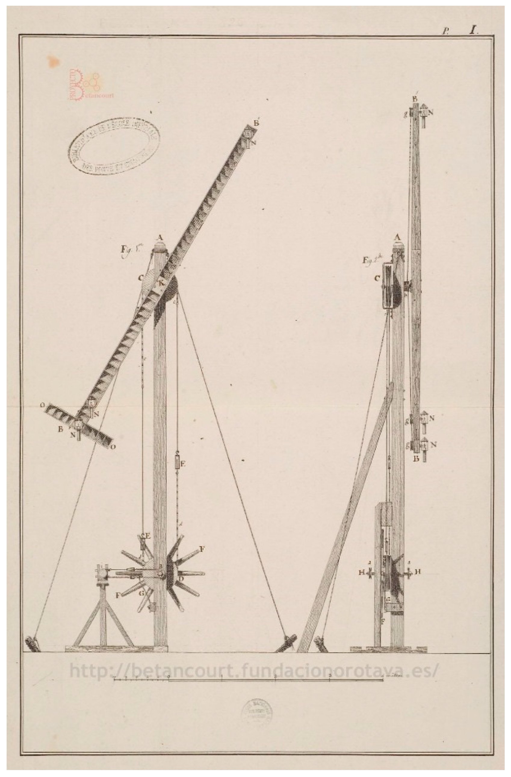
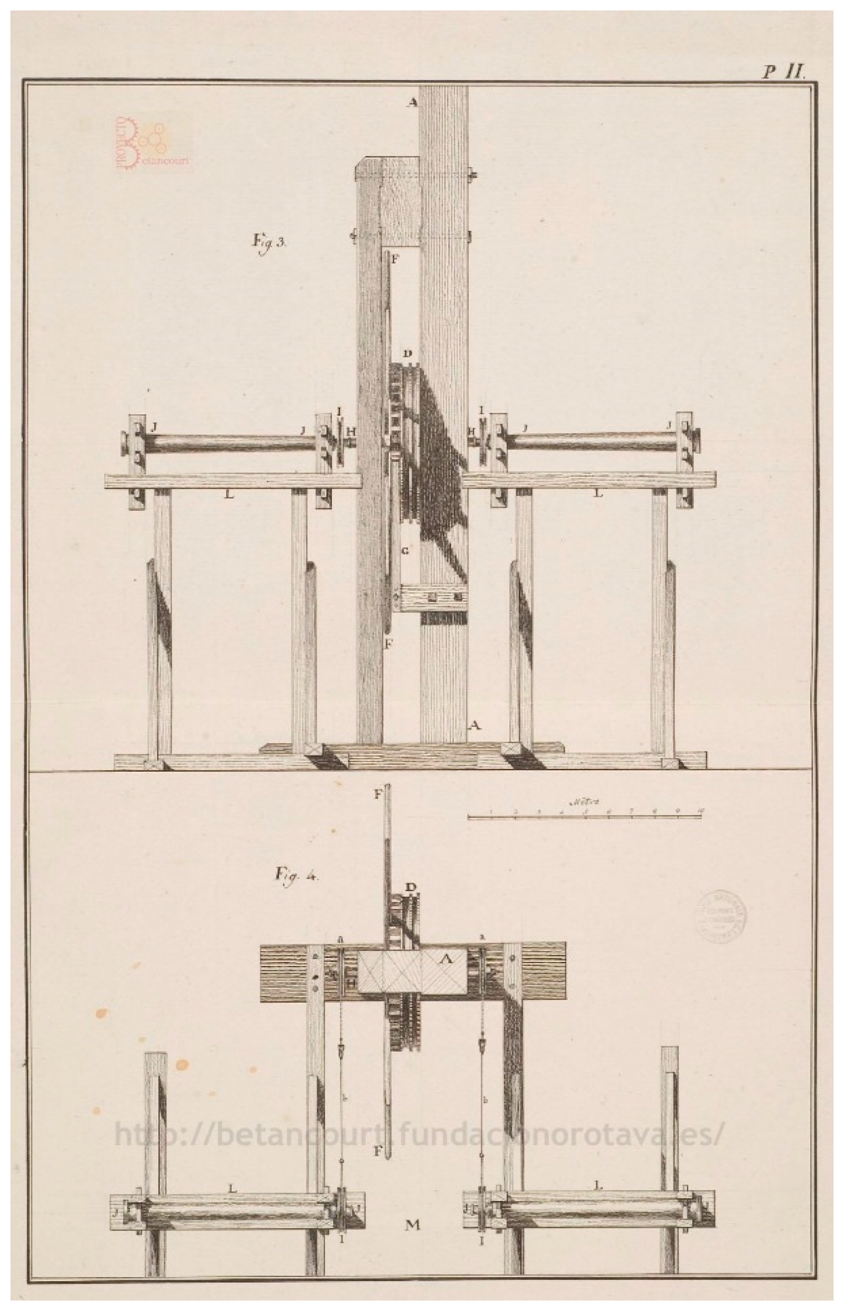
The material used in this research was obtained from two files on the Betancourt Digital Project website of the Canary Orotava Foundation for the History of Science [17], assigned for its digitalization by the National School of Bridges and Roads of ParisTech University. The first of these is manuscript 826 (MS 826), consisting of 3 sheets (Figure 1, Figure 2 and Figure 3), and a descriptive memory of 26 pages written by Betancourt and Breguet [18] and divided into two parts: one dedicated to the explanation of the 3 sheets and the operation of the optical telegraph, and a second where the authors defend their ideas on how telegraphic language should be. The second is the 1806 (MS 1806) which contains several documents related to the optical telegraph [19].
The drawings used to model the telegraph appear with their respective graphic scales, which has greatly facilitated the correct dimensioning of each of the telegraph elements. The drawings, despite being plans as they are conceived today, are rich in constructive detail and surprise with their clarity. The possible doubts that have been generated, in some cases, by the lack of orthographic views are resolved thanks to the memory written by Betancourt, which details the operation and purpose of each element.
The first sheet (Figure 1) presents a general view of the elevation and the profile of the optical telegraph. In some parts, it omits details of the frame or support, which can hide important parts of the mechanism. The second sheet (Figure 2) shows a longitudinal and a cross section that highlight the relationship between the frames, showing in detail the transmission from one to the other by means of the transmission that joins the pulleys. The third sheet (Figure 3) is divided into two parts: the left part shows the elevation and plan views of the gimbal joint, while the right part illustrates the positions that the optical telegraph can take. The upper right part shows how the optical telegraph can be placed on a different work plane from the immediate telegraph stations (previous and rear), while the lower right part details the signs transmitted by the optical telegraph according to the direction the indicator arrow adopts.
Thanks to these drawings it has not been necessary to make assumptions about the geometry of the elements to be modeled, a rare aspect in other inventions of the same author, since the function of the plans at the time was to describe the function of the invention and not the to give details regarding its construction.
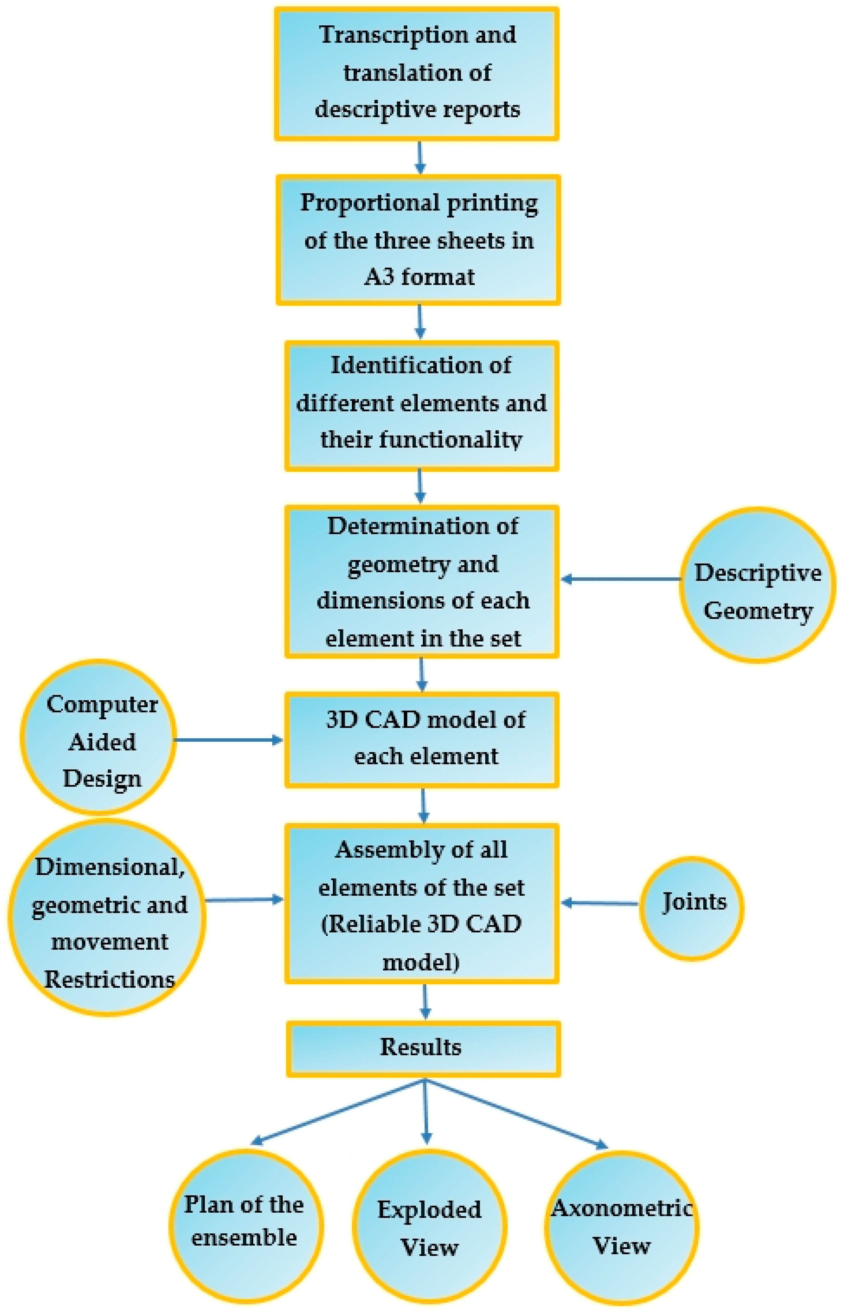
The research methodology has followed these steps:
- Transcription and translation of the descriptive reports of the two files described above (MS 826 and MS 1806).
- Proportional printing of the three sheets of the MS 826 file in an A3 format to directly take the measurements of the elements and apply the graphic scale present in the drawings.
- Identification of the different elements and their functionality in the set.
- Determination of the geometry and dimensions of each element, once its dihedral projections have been identified thanks to our knowledge of descriptive geometry [4].
- Obtaining the 3D model of each element using parametric CAD software.
- Assembly of all elements of the set by applying restrictions and joints. The restrictions (dimensional, geometric and of movement) allow us to define the degrees of freedom that the adjacent elements must have in their movement, while the joints do not present degrees of freedom. All this has allowed us to obtain a 3D CAD model of the set that is coherent and functional, reflecting the mechanical and structural characteristics of the mechanism.
The entire process described above is shown as a summative flowchart in Figure 4.
For CAD modeling tasks the software used has been Autodesk Inventor Professional [20] which has allowed us to obtain the 3D CAD models of each element, generating a file with extension (.ipt) and finally the assembly of the whole, generating a file with extension (.iam). Moreover, each element has been assigned material with certain physical properties in order to obtain a model that is closest to reality.
Three-dimensional CAD modeling techniques constitute a very important tool in the process of the study and design of historical heritage, for example, in the fields of cultural heritage [21], aerospace [22], civil [23], horological [24], architectural [25], and more generally, in the study of any virtual model [26,27,28], as a previous step to CAE analysis [29,30].
3. Results
3.1. Considerations and Functioning
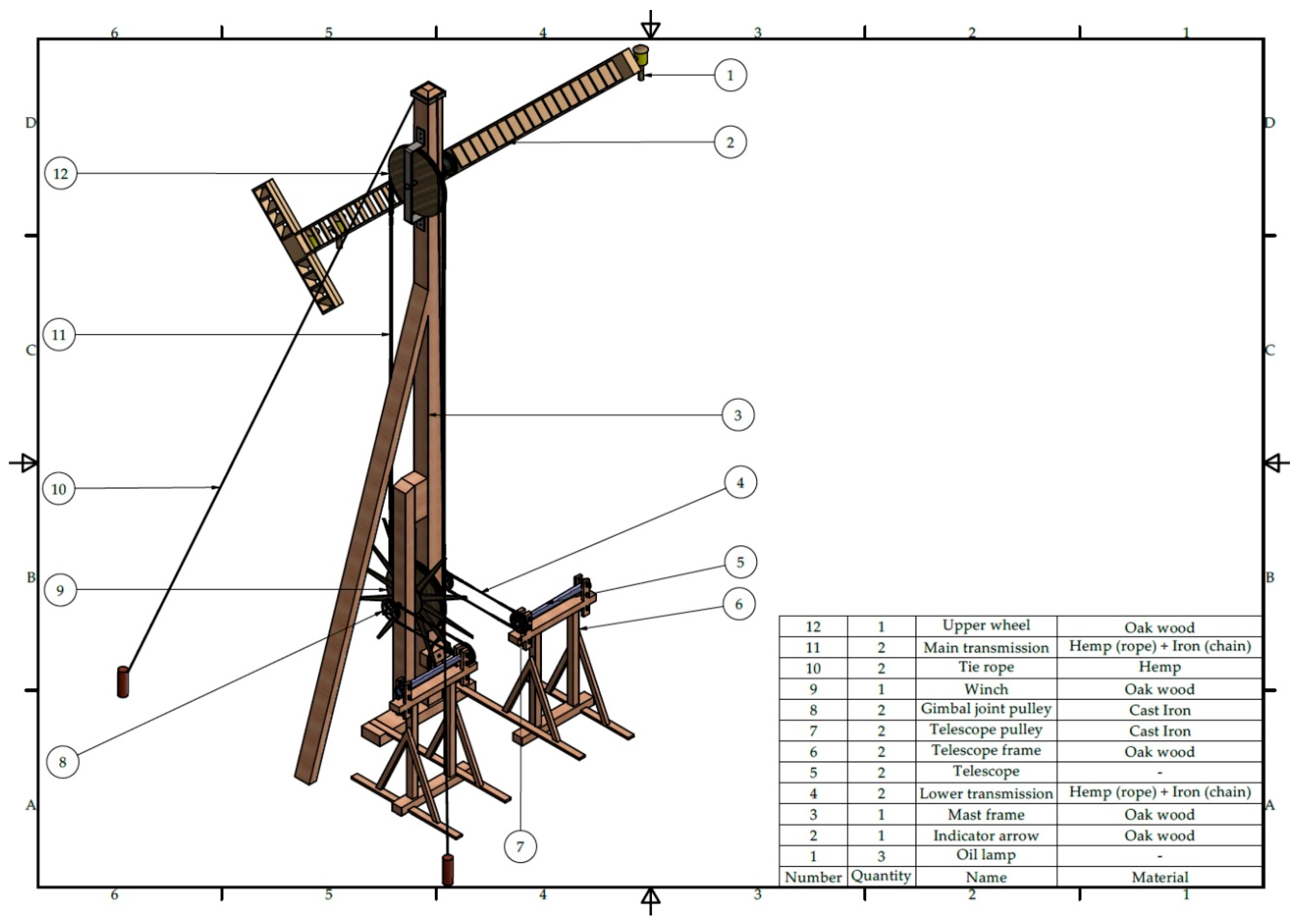
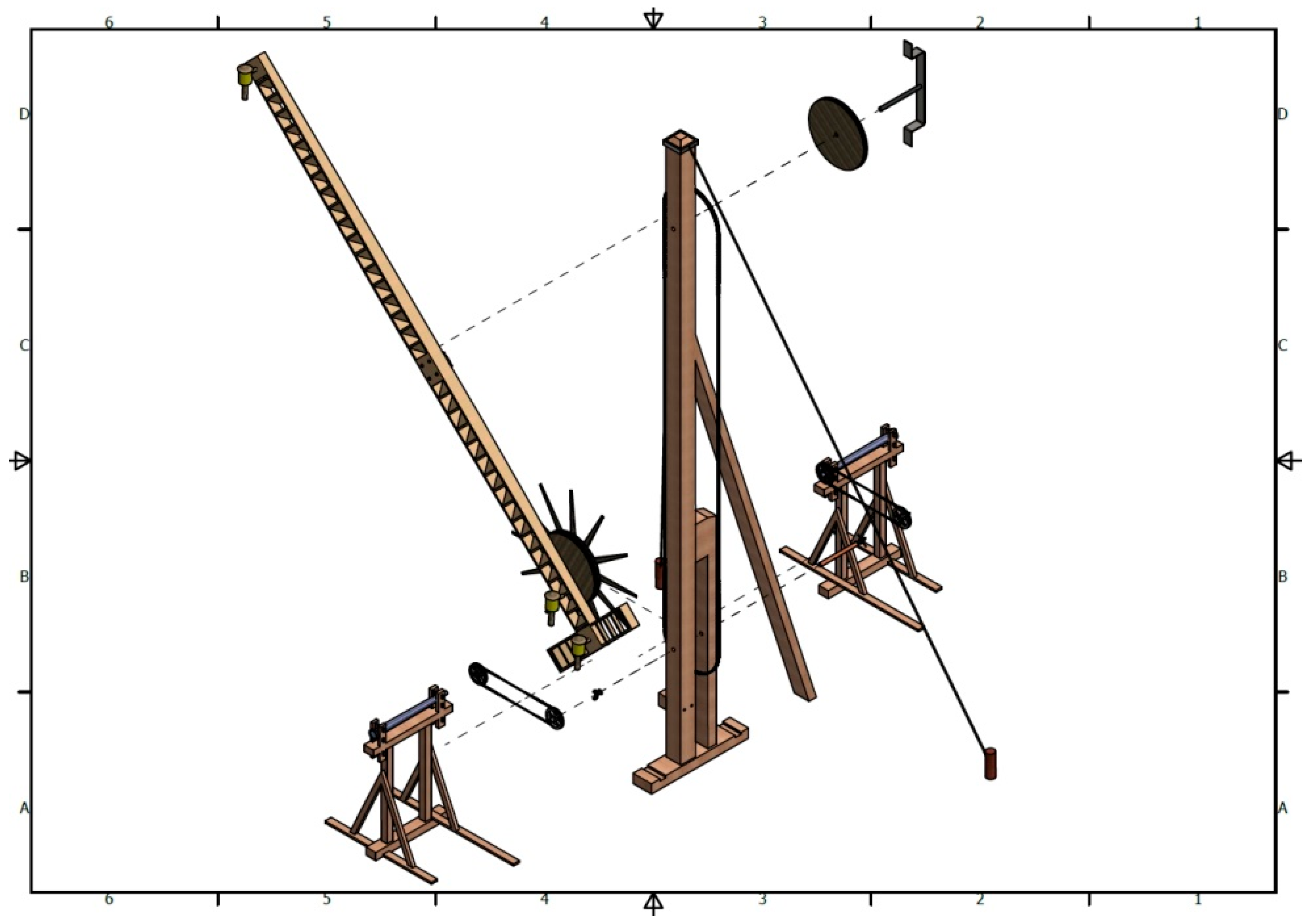
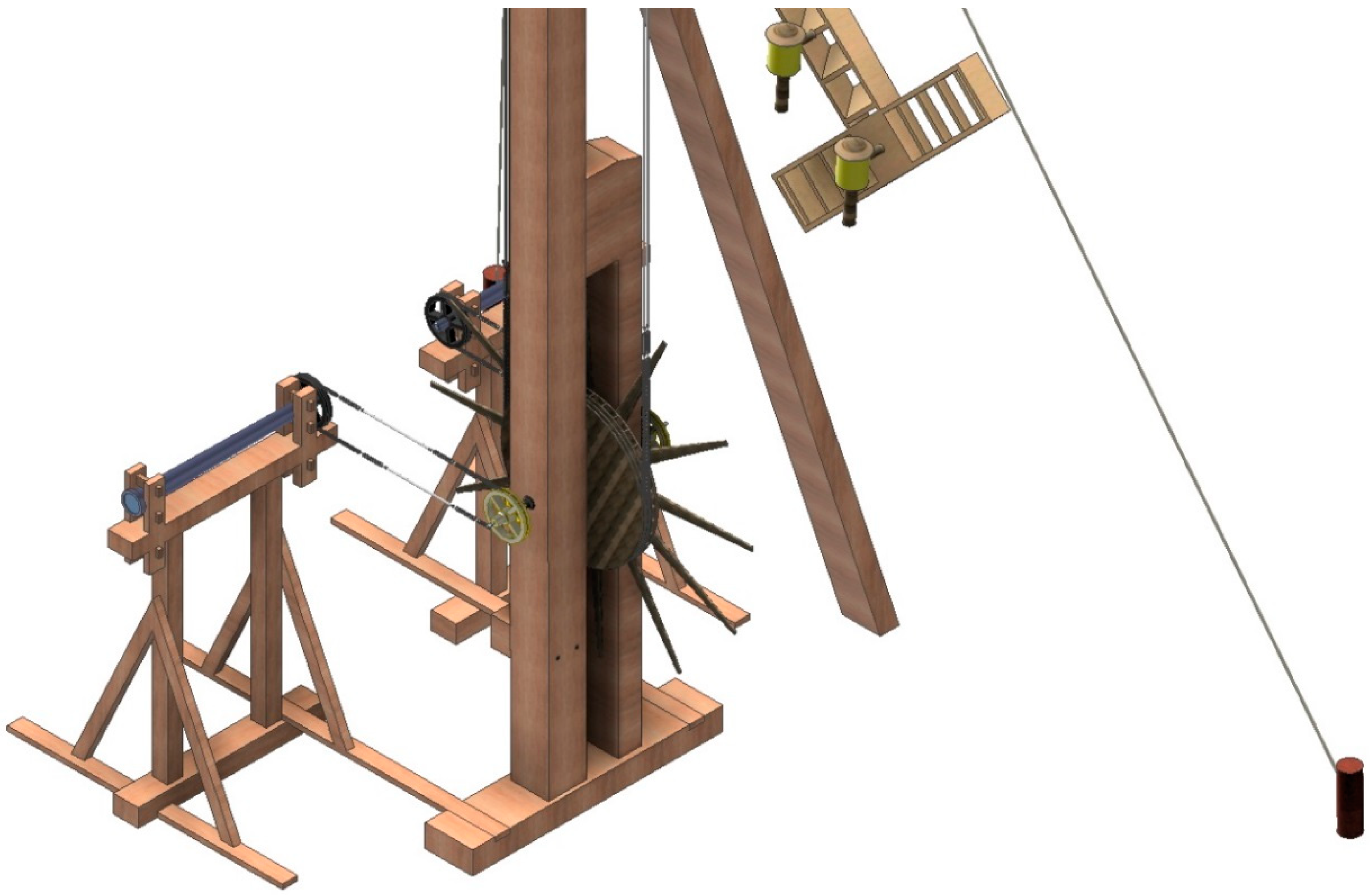
In order to give the reader a complete idea about the analysis of the invention of Agustín de Betancourt it is necessary to explain its operation. Figure 5 shows a plan of the ensemble with an indicative list of the different elements that form it which will serve to illustrate the operation of the mechanism, and Figure 6 shows an exploded view of the overall invention for a better understanding of the direction and order of assembly of the different parts of the optical telegraph.
The operation of the Betancourt optical telegraph is based on the relationship between the indicator arrow (2) and the mast (3) with which it forms a certain angle easily visible over large distances. The directions that the arrow can adopt are taken over preset positions corresponding to the transmission code signs. The indicator arrow revolves around an axle that allows it to adopt any direction of an imaginary circle, dividing it into thirty-six sectors which correspond to numbers or letters of the alphabet. Comprising 36 divisions, each sector covers an angle of 10° sexagesimal: the first positions correspond to letters of the alphabet and the rest to ten figures (from 0 to 9).
Firstly, in order to change the position of the indicator arrow a manually operated main transmission (11) is necessary. In the lower part of the mast, there is a winch (9) with 36 slots, which was operated by the operator until the tip of said indicator arrow was placed on the slot with the mark of the alphanumeric character to be transmitted. In a similar way, the main transmission (11) communicates the movement of the winch (9) to the upper wheel (12) which is integrated with the axle of the indicating arrow so that turning the winch rotates the arrow, adopting a certain position. The aforementioned main transmission (11) is singular, since it is formed by two long pieces of hemp rope fastened at its ends by a chain of flat links joined by bolts, very similar to those used in current transmissions. Finally, the telegraph operator looks through the telescope’s eyepiece (5) for the arrow position of the preceding telegraph to make sure that its arrow has the same position.
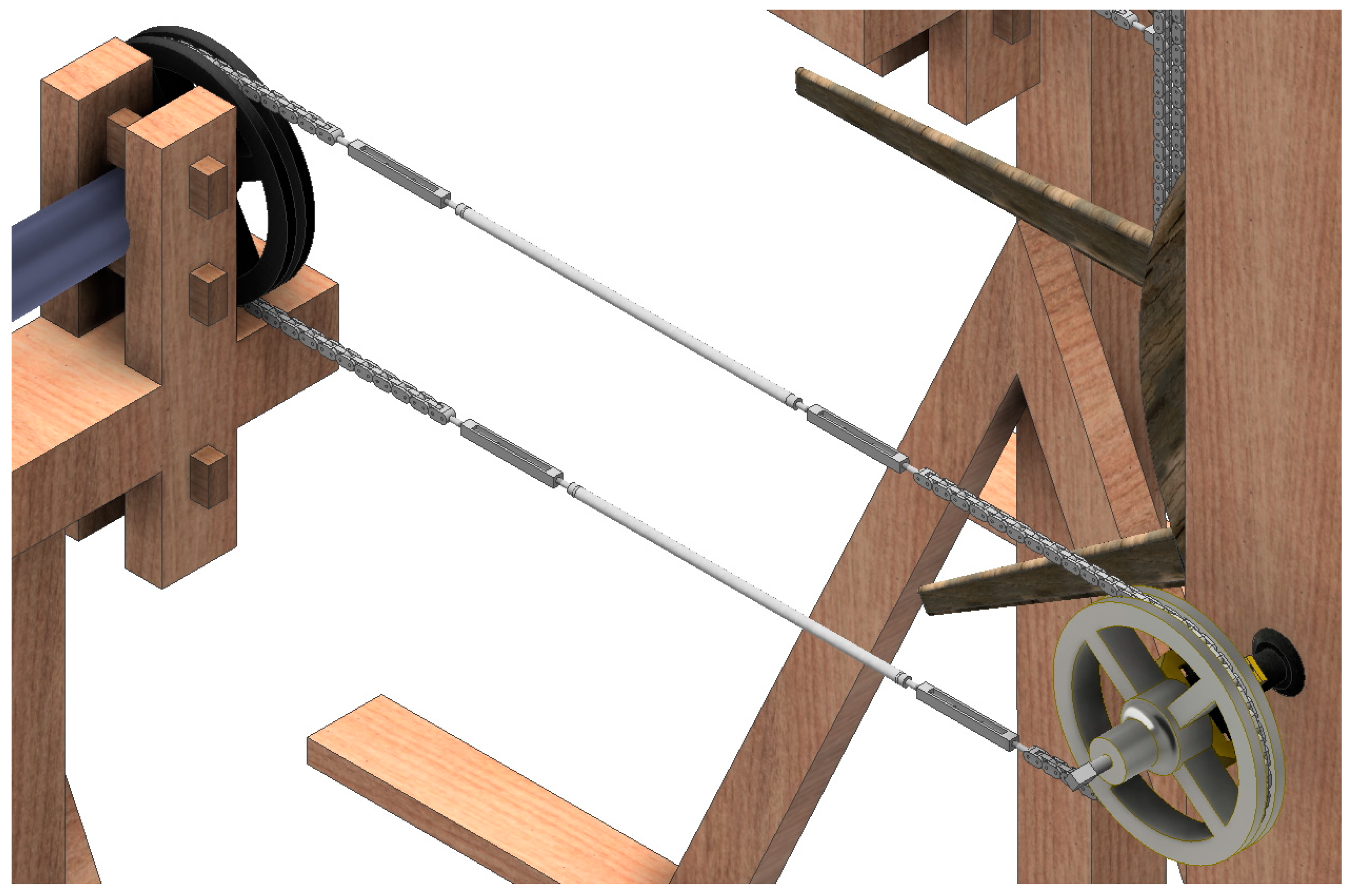
Each telegraph has two telescopes perfectly fixed in two wooden frames (6), which gives them stability and serves to keep them pointing in a certain direction (the one of the nearest telegraph: before or after). This telescope can rotate on its longitudinal axle without ever losing the direction of the immediate telegraph, and in addition it is housed in a pulley (7) arranged transversely to its main axle. This pulley (7) is also joined by a transmission to another pulley (8) joined in turn by a gimbal joint to the axle of the winch. This gimbal joint allows the telescopes to be rotated at the same time as the winch, thanks to a lower transmission (4) existing between them, similar to the main transmission (11) mentioned above.
Furthermore, the telescope’s eyepiece is provided with a meridian wire that serves to show the position of the indicator arrow of the telegraph itself. Thus, if the operator observes that the indicator arrow of the preceding telegraph changes the winch will rotate until the position of its arrow is the same as that of the preceding telegraph. In the same way, the operator can see if the rear telegraph station indicates the position that he has transmitted and will not change position until it is transmitted correctly.
An important consideration is that telegraph stations do not have to be perfectly aligned for proper operation, that is to say that it is not necessary that the frames be arranged in parallel, since the gimbal joint allows the transmission work plane to be different from that of the circle formed by the indicator arrow.
Finally, the indicator arrow has three oil lamps (1) that allow the telegraph to continue operating at night, since they indicate the direction of the arrow in the dark, the operating mode being the same as in full daylight.
3.2. Optical Telegraph Assembly Process
The Betancourt and Breguet optical telegraph was a simpler mechanism to assembly than any of the contemporary telegraphs, although in any case it is a structure that when its mast and arrow are aligned has a minimum total height of 9.85 m (if it is true that, depending on the needs of the location, it could reach more than twenty meters high). A precision mechanism of these dimensions requires a fairly careful assembly, and therefore the study of the mechanism and its modeling using CAD techniques has enabled the authors of the article to gain a special awareness of the delicate assembly of the telegraph which we will now describe.
In the first place, for the correct assembly of the telegraph, it is necessary to judiciously choose the location of the telegraph station. The operator should have a direct and clear view of the immediate stations. Thus, a location aligned as much as possible with respect to the preceding and subsequent station was chosen, facilitating installation and reducing the possible optical error. Once this location was chosen the plane of the telegraph (plane defined by the circumference described by the indicator arrow) was located as parallel as possible to the planes of the immediate telegraphs, and if this was impossible to measure (there were already compasses at the time), taking the direction perpendicular to the one drawn by the segment that joined the immediate telegraphs. Thus, the frame that held the mast (3) should be perfectly aligned knowing these data, and the structure of the mast should not be raised until a series of elements were placed on it, since once it was lifted it, would be necessary to place a large structure to assemble the rest of the elements.
With the mast on the ground, the first element that was to be placed was the winch (9) with its axis, positioning it perpendicular to the structure of the mast. Once in position the shaft had to be fixed by placing the two gimbal joints on the outer faces of the frame, which do not prevent the shaft from rotating but do prevent its axial movement.
The next operation was to place the upper wheel (12) with its own axle. In order to do this, the axle had to be placed in its exact location, the wheel housed and finally the metal structure fixed which gave a second point of support to the axle. Thus, the wheel and the winch were still in place to insert the main transmission (11) before lifting the mast. The main transmission was one of the most delicate elements to place in the mechanism. As explained in the description of the invention, the main transmission was formed of a middle zone and two extreme zones. The middle zone was constituted by a hemp rope and the extreme zones were two chains of flat links, and the join of both elements was achieved by means of a tensor that when turned moved its ends closer together. For the assembly of the main transmission one of the tensors needed to be detached from the two ends. Thus, the part of the chain transmission was placed both in the groove of the wheel (12) and in the groove of the winch (9) and once in position the tensor was put in place and the main transmission tensioned (11). This operation had to be performed at least twice since the transmission was double, that is to say there were two main transmissions in parallel. Once it had been verified that, when turning the winch, the upper wheel turned in the same direction, it was time to lift the structure.
In order to raise and fix the structure two ropes (10) were necessary, acting as struts of about 12 m in length, which served to give stability to the structure and prevent its swaying. One end of the rope was tied to the head of the mast while the other was attached to an anchor in the ground. Moreover, the structure of the mast has a counterweight on the side opposite the arrow that also supports the mast, which also helps to gain stability in the structure. Finally, once the structure was lifted, it was fixed to the ground by two long anchor bolts.
After this operation the frames (6) of the telescopes were installed. This was one of the most delicate tasks since the frame had to be fixed to the ground once the telescope was pointing in the right direction, something that was also achieved by means of anchor bolts, and in order to obtain the correct direction it was essential to have a signal indicating at least the position of the immediate telegraphs. Thus, once the two frames were oriented, the telescopes were placed and fixed (5) by means of a wooden clamp which allowed them to rotate but not to move axially. The telescopes on the other hand were not normal since the end of the telescope’s eyepiece was housed in a pulley (7). Once the telescope was placed and after making sure that it pointed clearly to the nearest station, it was rotated until the meridian wire in the eyepiece was arranged vertically.
The transmission mechanism between the telescope pulley and the winch made it easy to control the position of the telescopes from the winch. The gimbal joint was connected by a pin to a pulley (8), and this through a lower transmission (4) communicated the movement to the telescope pulley (7). The assembly process, therefore, was very similar to that of the main transmission: first the gimbal joint pulley (8) was mounted by the aforementioned pin, and then the transmission was placed on them, inserting the chain into the grooves perimeter of both pulleys. The transmission also had a central part of hemp rope and two extreme zones of flat metal links. In the assembly process, it was very important that both the telescope and the winch were fixed in the same position (the meridian wire in vertical position and the winch pointing to the vertical position of the indicator arrow). Again, one of the two link chain tensors had to be detached from it while the lower transmission was placed in its position and tightened until it was tight. This operation had to be performed twice, once for each telescope.
The final step to finishing the assembly was the placement of the indicator arrow (2) on its axle. Obviously this process was simple if the mast measured only a few meters, but if the mast measured more than 10 m the process presented more complexity, since it was necessary to install the structure using a crane and with the help of many operators, because the indicator arrow alone measured 6.60 m. The indicator arrow mounted separately with its three oil lamps (1) and its transverse base should be placed on its axle in an upright position and with the horizontal arm in the position closest to the ground. Once inserted it should be fixed to the horizontal axle by four bolts in order to secure it perfectly. This horizontal axle was undoubtedly the piece that was going to endure the majority of the stresses to which the mechanism would be subjected, and the useful life of the mechanism depended on its correct installation. After this step, the mechanism would be in perfect condition for use.
3.3. Three-Dimensional Modeling of the Parts and Final Assembly of the Three-Dimensional CAD Model
The modeling process of the optical telegraph is long and should be performed in great detail, paying close attention to the detailed information offered by the drawings.
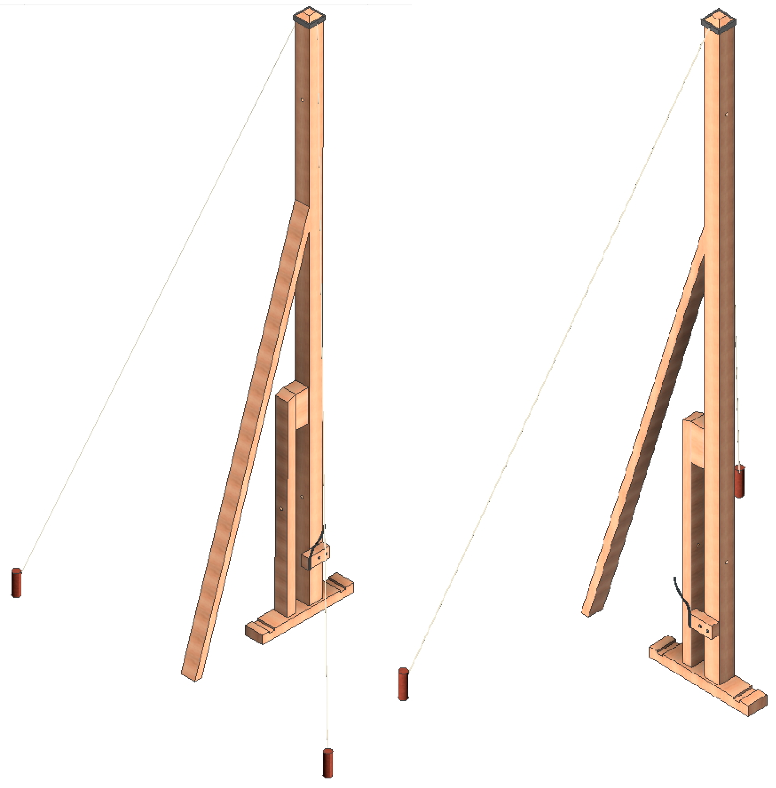
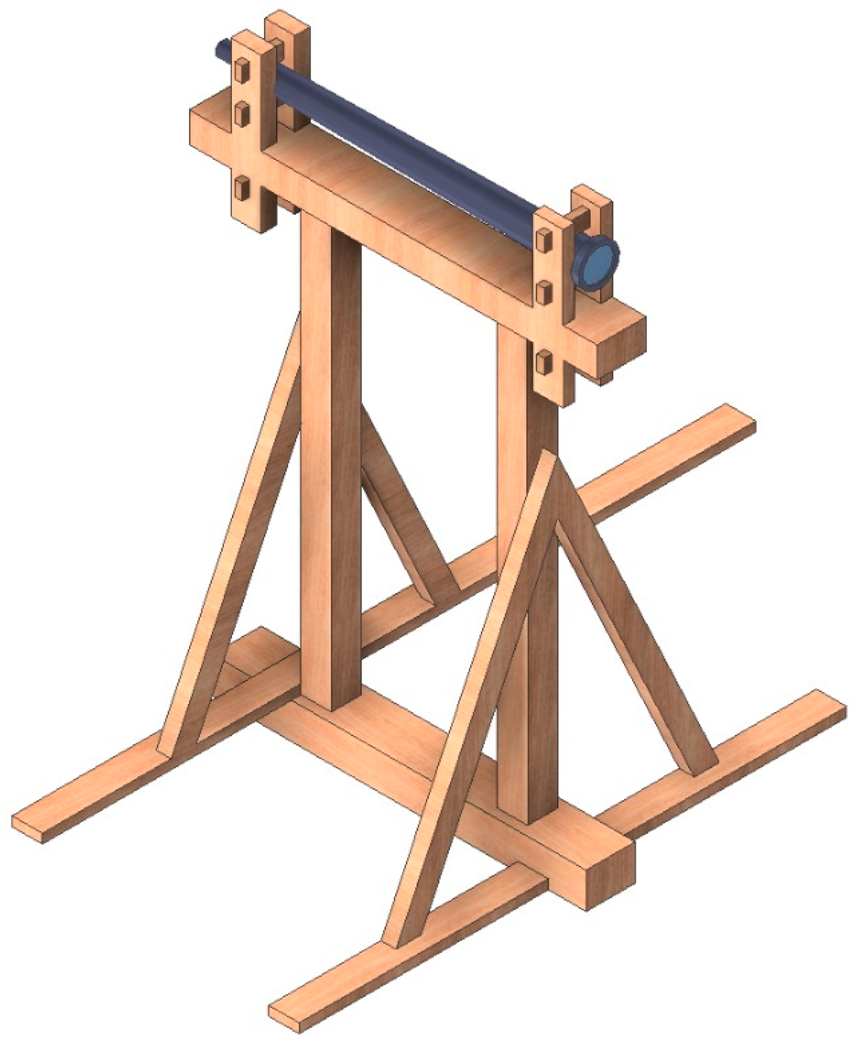
First, the mast frame is modeled (Figure 7). This wooden structure is the skeleton of the invention, and it is important to respect the distances of the holes where the different axes will be housed. The mast is 7.45 m high and rests on a support that is 1.32 m long. This structure is not enough to give stability to the mast, therefore, from the central body of the mast, there is a support that allows the base to be extended to 2.27 m. In a similar manner, Betancourt, aware of the wind resistance that the structure presents, proposed a system of supports to guarantee the stability of the structure, and on the other hand the proposed dimensions of the mast and its structure will always depend on the topographic conditions of the environment. Its function is structural, but it must also be able to place the indicator arrow at a sufficient height, and if the conditions require it to be extended.
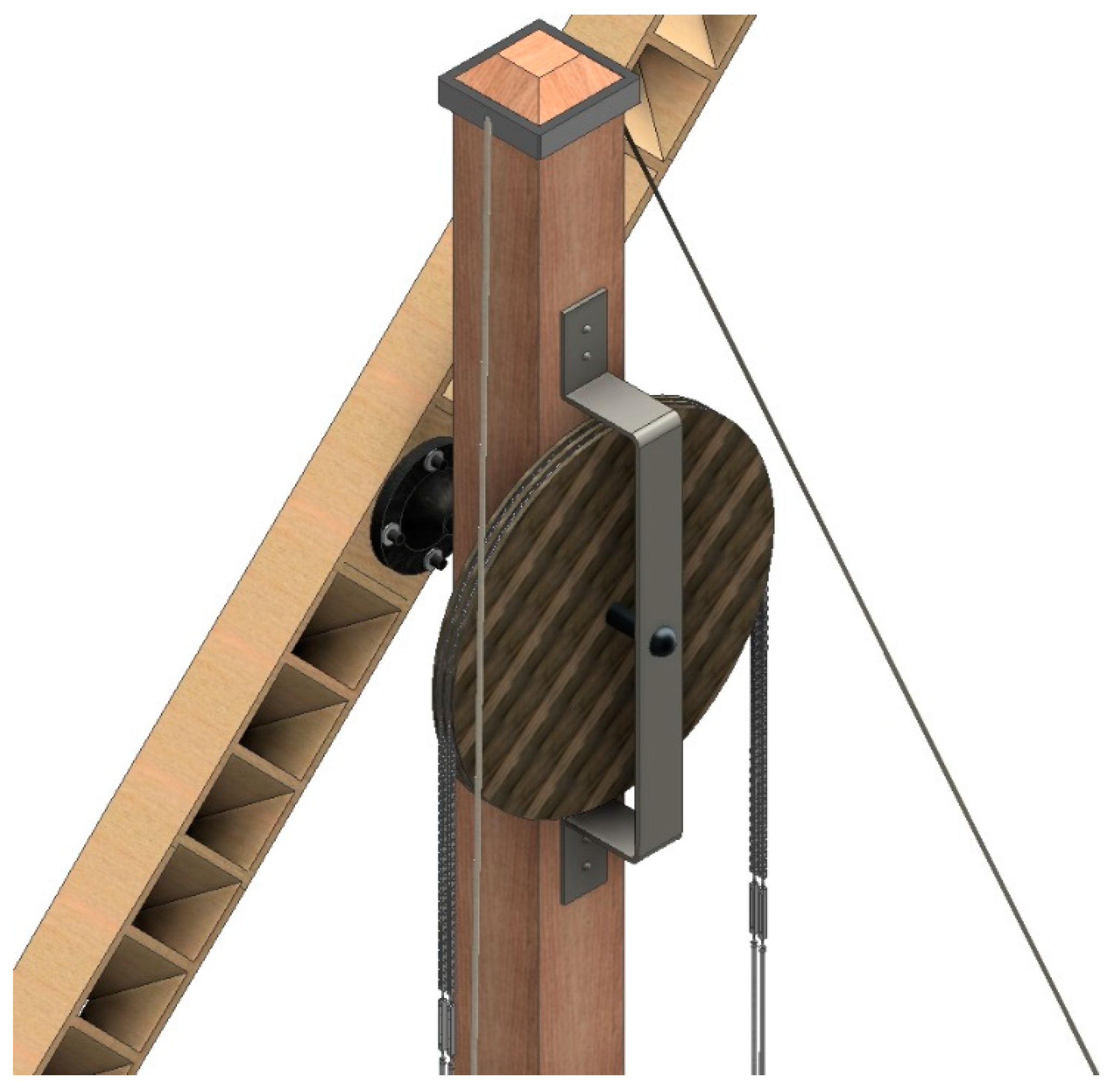
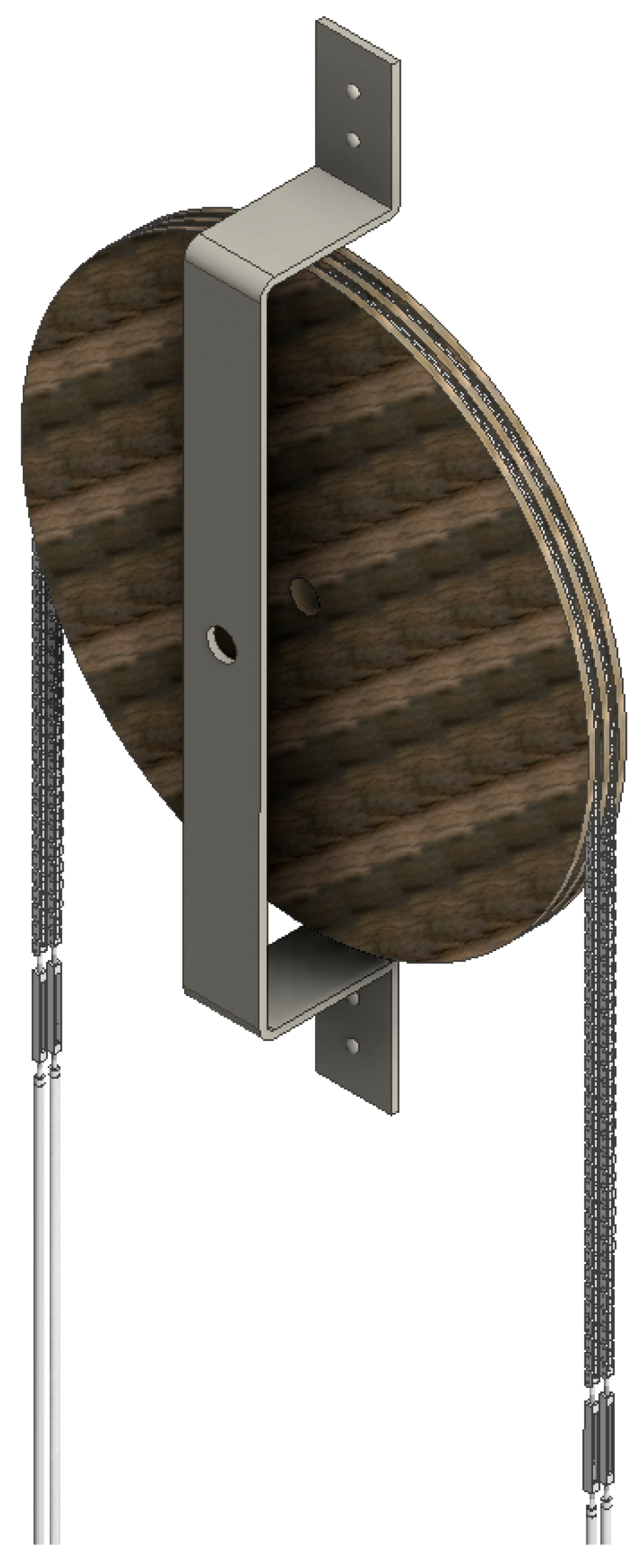
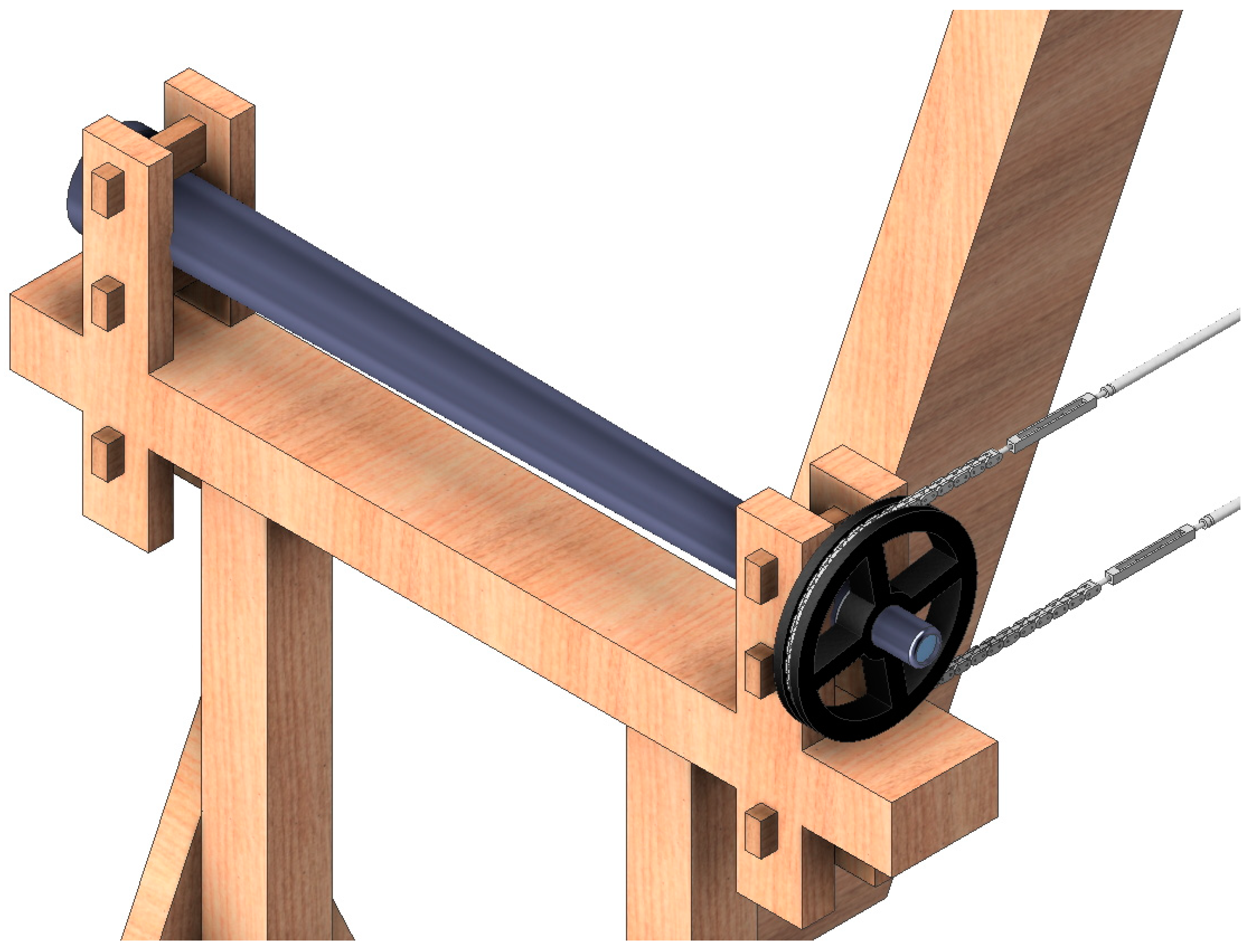
The next structure to model is the upper wheel (Figure 8). This is a wooden pulley of 75 cm in diameter in whose perimeter there are two grooves where the main transmission chain will be housed. This wheel is fixed to the mast thanks to a metal axle, and this in turn is supported externally by a metal structure that is screwed to the mast. The structure allows the axle to be perfectly horizontal and the wheel to rotate freely.
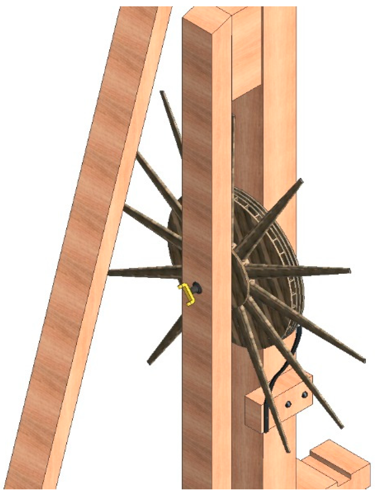
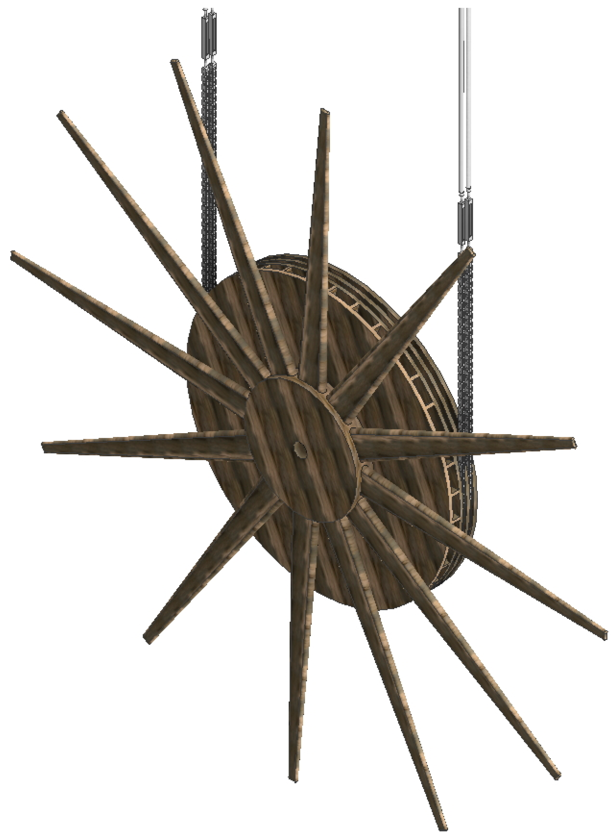
On the other hand, there is the wooden winch, which is one of the most important elements of the mechanism (Figure 9). This is a wooden wheel of 75 cm in diameter in which there are also two grooves in the perimeter zone, as in the upper wheel, but not in the middle area of the wheel rather towards one side. The other part of the wheel is drilled every 10º so that the sectors in which the wheel is divided can be perfectly distinguished. These divisions will be used to position the indicator arrow in a certain direction. The winch in addition has 12 arms of 1 m in length that facilitate its maneuverability, and in turn is crossed by a metal shaft that has a double function, positioning the winch in the mast support and allowing it to rotate freely.
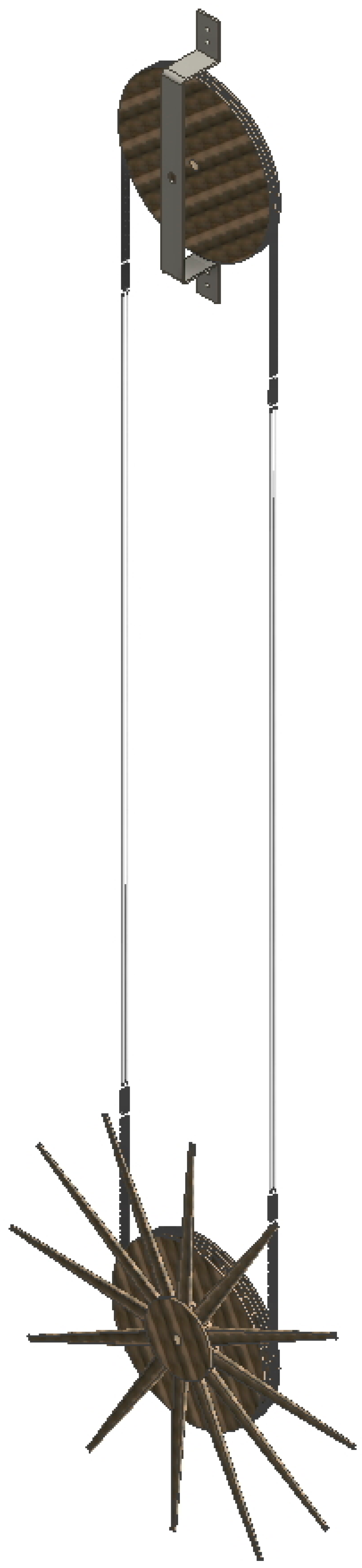
Figure 10 shows the position of the winch on the mast frame, giving a very clarifying overall view.
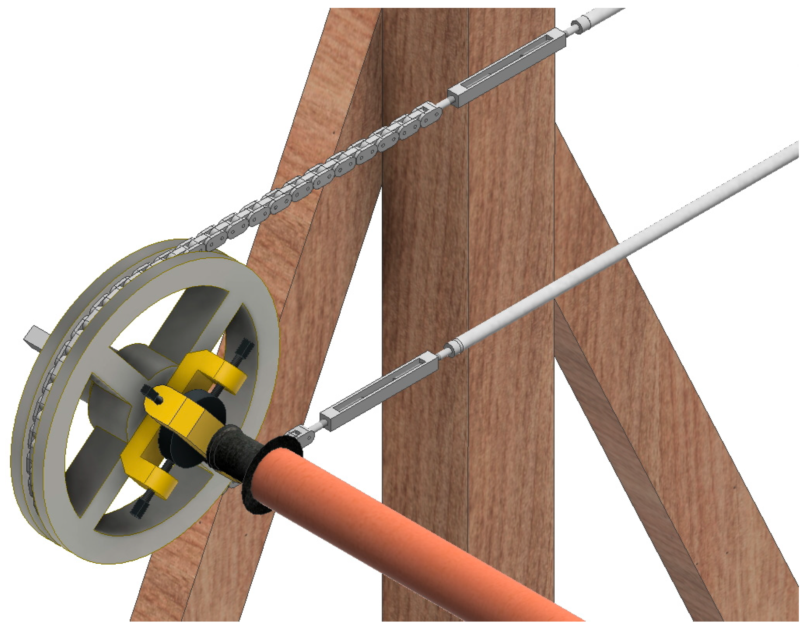
The main transmission, the one that connects the upper wheel and the winch (Figure 11, Figure 12 and Figure 13), is the most complex modeling element of the mechanism. If the drawings and Betancourt’s memory are taken carefully, it is discovered that the transmission that communicates the movement from one to the other is not achieved by a simple hemp rope, since the use of a rope presents the inconvenience of its sliding inside the slit due to the inertia of the movement of the indicator arrow. In order to avoid this slippage, Betancourt proposes a mixed rope-chain transmission system. The belt-like transmission has a central part of the rope and a part of the metal chain that comes into contact with the pulleys. Between them, there is a metal tensor whose mission is to provide greater tension to the transmission or to facilitate its repair tasks.
The modeling of the hemp rope is simple, although from the structural point of view it is very problematic. Most CAD software represent ropes as static elements when their behavior is dynamic. Also, the section and the length of the rope change as a tension is applied to it and no conventional design software is able to simulate this. Therefore, from an aesthetic point of view, the design of the rope does not offer much complication, but if it is intended to use the CAD model for a subsequent CAE analysis, then the model is insufficient.
The modeling of the chain of flat links is very laborious since it is necessary to model each link with its own bolt, defining a relationship between them that allows it to rotate with respect to each other. As can be seen in Figure 14, this chain of links in its description is very similar to that of a current flat link chain transmission, although evidently Betancourt did not know this type of transmission and defines links much larger than those of a current chain.
It is known that at the time there were no standardized elements and that each metallic element had to be handmade, so a chain of these characteristics was very complex and required a great manufacturing effort. Therefore, in practice, and for a large number of telegraph stations, it is not surprising that rope transmissions were used instead of mixed transmissions. Finally, it should be noted that the transmission was double in order to ensure the correct synchronization between the indicator arrow and winch.
Next the telescope frame is modeled (Figure 15). This frame is a simple wooden structure 1.53 m high, 1.45 m wide and 1 m long, which has the function of housing the telescope through which the nearest telegraph station is observed. For this the wooden clamp must at all times allow the telescope to rotate freely while preventing its longitudinal movement, although the telescopes frames do not have to be aligned with respect to the mast frame. In this article, they are presented as aligned, but their position depends on the direction in which the nearest station is located.
Once the telescope has been modeled, a 22 cm diameter metal pulley is attached to the rear of the telescope where the eyepiece is located (Figure 16). When the pulley rotates, the telescope rotates in unison.
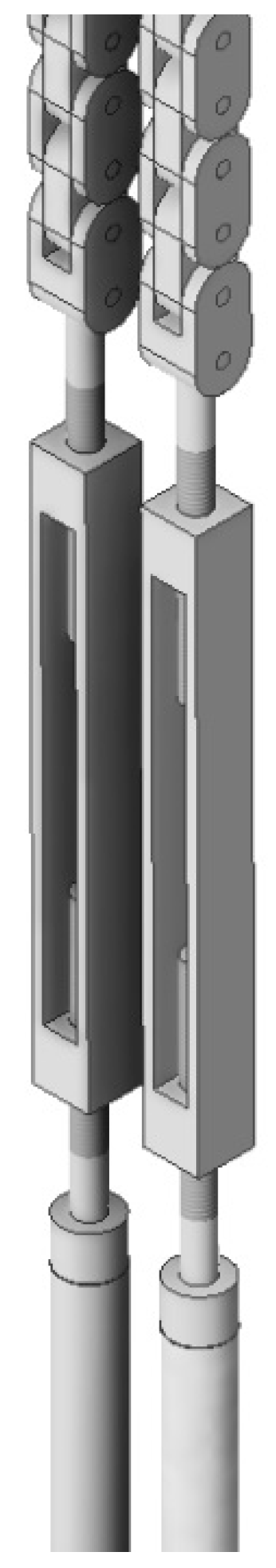
The next step in the modeling, also technically complex, is that of the pulley attached to the gimbal joint (Figure 17). The first element to model in this case is the end of the winch axle where a U-shaped metal piece with holes drilled in its two tips is to be placed. The next element is a circular piece that has two main axes, each axle being a metal rod of circular section topped by a square section that prevents it from passing through the hole. In addition, one of the axes goes through the two holes of the U-shaped metal tip mentioned above. It is important to define the relationship of these two elements correctly so as to allow the circular piece to rotate freely.
Next a metal pulley of dimensions and characteristics similar to that used in the telescope is modeled, but with a difference: located on one of its faces it has a U-shaped metal piece similar to that of the axle but placed perpendicularly and facing its ends. The tips of this piece are also drilled and its purpose is to house the free shaft that the round metal part possessed.
This articulation, made with these two U-shaped metal parts and the two-axle circular piece, is what is commonly called gimbal joint or universal articulation, and it allows the rotational movement of one axle to be converted into the rotational movement of another axis arranged in an unaligned direction. The use of this joint is what allows the telescope frame to not necessarily have to be aligned with the mast frame.
The transmission that is used between the metal pulleys (the one attached to the gimbal joint and the telescope pulley), has similar characteristics to the transmission between the upper wheel and the winch, but with a lower number of links (Figure 18).
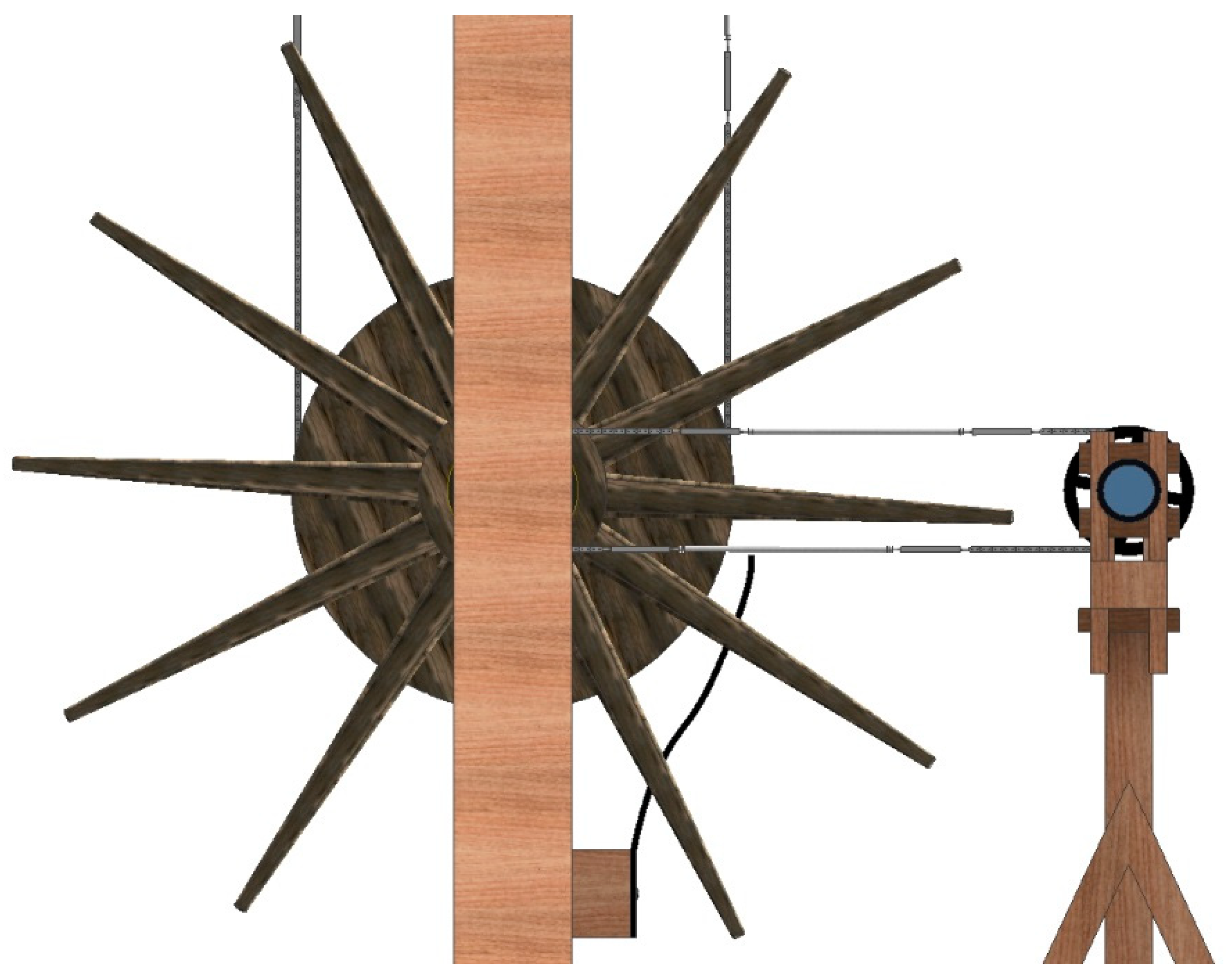
After modeling the transmission, we can see how moving the winch makes both telescopes rotate simultaneously at the same angle (Figure 19).
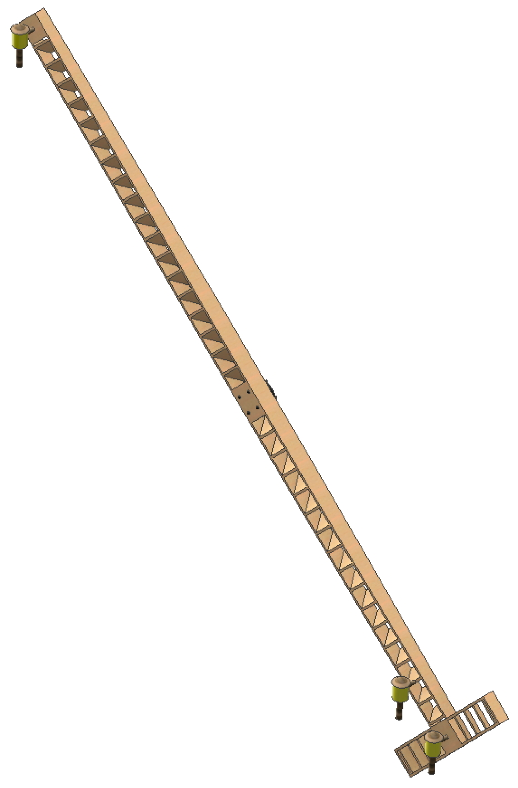
Figure 20 shows the modeled indicator arrow. As can be seen, it is a simple T-shaped structure of 6.60 m in length, with its interior emptied so that it offers less wind resistance. The indicator end is signaled by an oil lamp, which could be lit if necessary, and the transverse part of the arrow (opposite end) is in turn signaled by two oil lamps. In this way, one end was also distinguishable from the other in the dark.
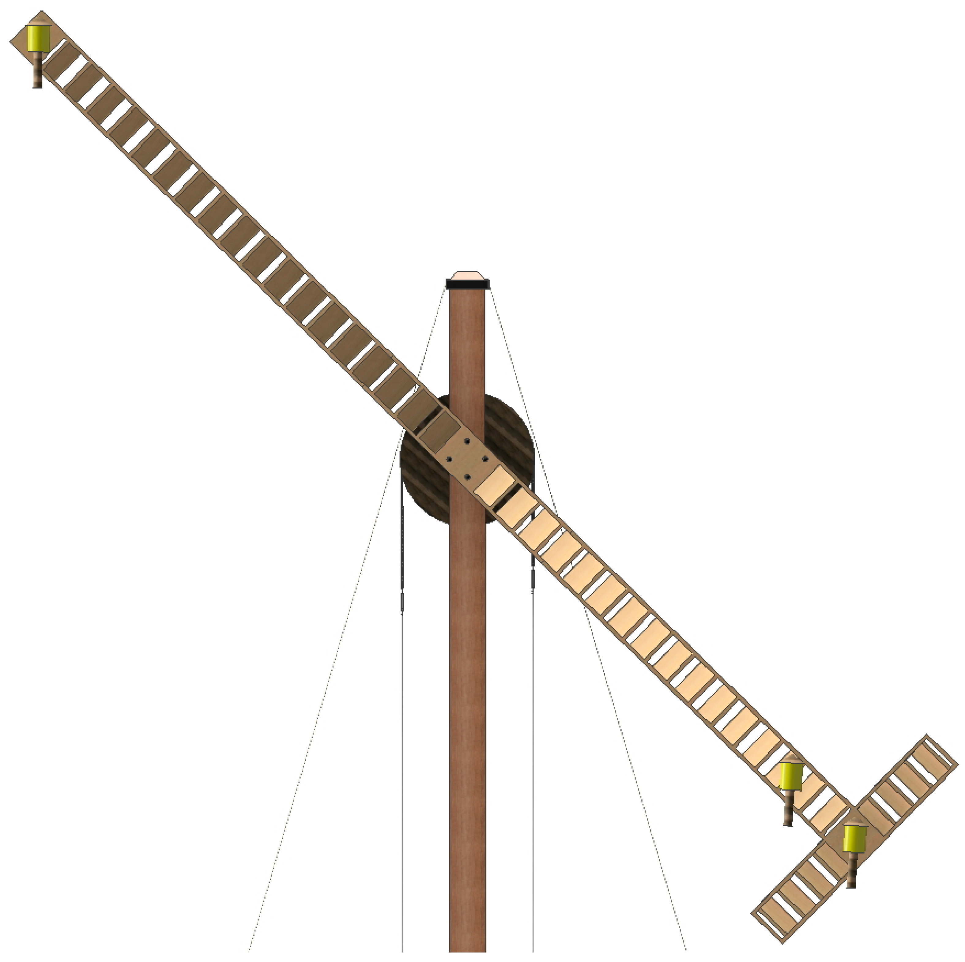
Once the indicator arrow has been modeled, it must be placed in its screwed position by means of four screws to the upper wheel (Figure 21) so that when the operator manipulates the winch the arrow rotates in unison with the upper wheel.
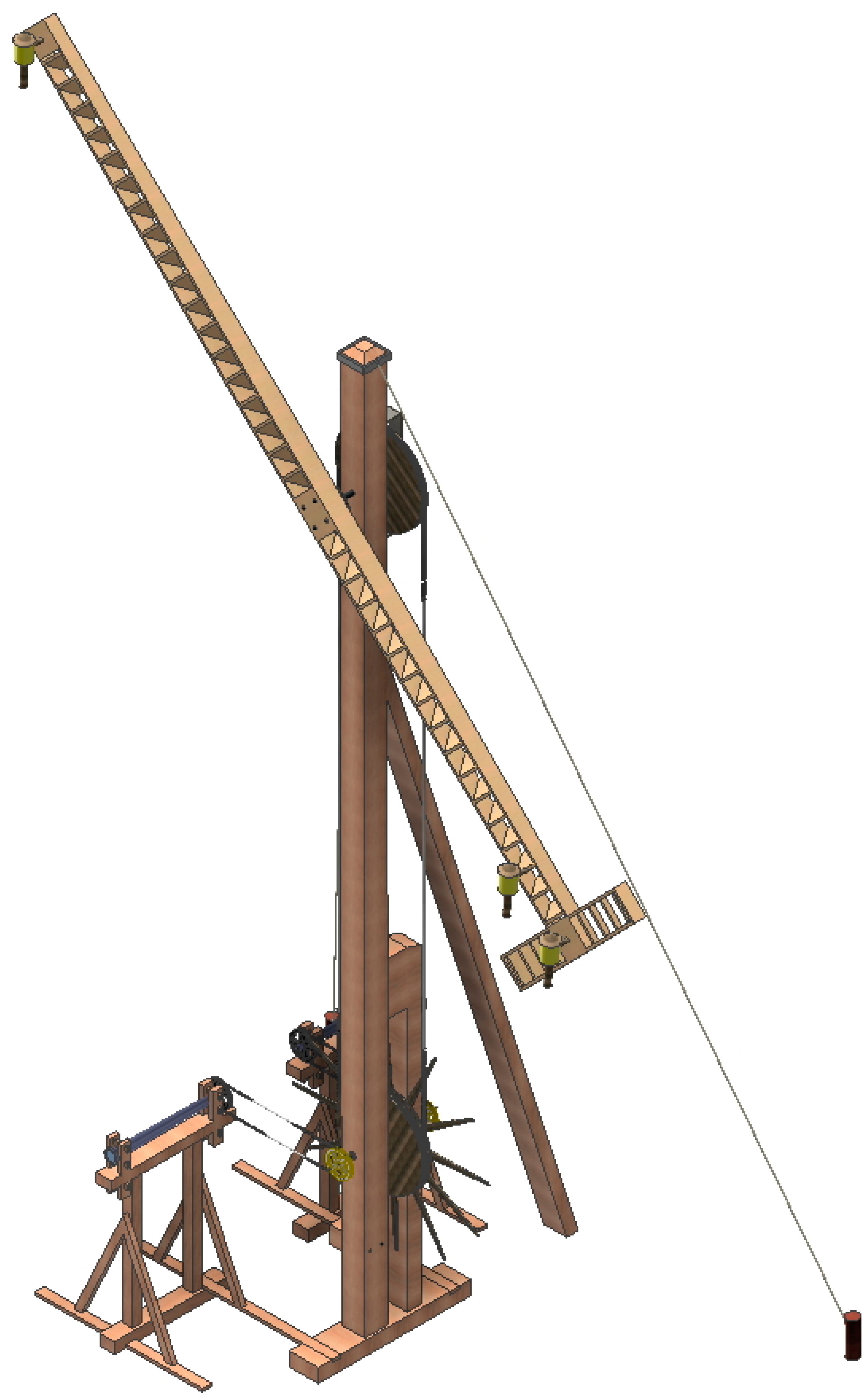
Figure 22 shows an axonometric view of the optical telegraph assembled with all its elements.
3.4. Discussion and Findings
The optical telegraph presented here possesses a series of characteristics that made it the most advantageous telegraph of its time.
First, it is a telegraph with a relatively simple assembly. The mechanism used for its operation is very basic, although somewhat more complex than that of the Edelcrantz panels, but in comparison, the set of transmissions and telescopes greatly simplifies its handling, since only one operator is needed who does not have to know the signs he transmits.
Secondly, the transmission method using only an indicator arrow makes the message clearly gain compared to the method of panels or two arms used by other telegraphs. The use of an indicator arrow allows the operator to use 36 positions, allowing him to use the conventional language of signs and numbers and not a complex network of codes.
Thirdly, the indicator arrow allowed the use of oil lamps to distinguish the signals at night, so as long as the visibility was adequate transmission of the message was not reduced to the hours of daylight.
On the other hand, the optical telegraph also presented a series of drawbacks that weighed down the life of the telegraph and that finally led it to disappear shortly after it was put into operation. Interestingly, among these drawbacks, only one is of a technical nature, and it was precisely the one that would go unnoticed at the time.
The use of telescopes entailed a small error that was not possible to avoid at the time. When sighting a telegraph at certain angles with a telescope (it has already been seen that it is not easy to accurately locate both the immediate telegraph plane and the observation plane), some optical deformation occurs in the reading. For example, for a 30° angle difference, the observation error is 4.6°. The measuring instruments of the time, especially compasses, did not allow for more precision when aligning these planes, although a 30º offset would be an excessive assumption since the sectors for the same signal are 10°. Therefore, it cannot be assured, that in any of the messages no mistake was made, although in general with that maximum error it would be perfectly acceptable.
On the other hand, the use of the gimbal joint could also generate some error in the transmission. In addition, at the time there were any mechanical studies on the movement of said gimbal joint, which is not homogeneous and, therefore, the transmission was not a synchronized movement between pulley (8) and winch (9). A study of the limits of the telegraph [14] provides more complete information on the subject, although the conclusion is that the error was negligible, partly due to the use of two gimbal joints for two telescopes.
The last drawback presented by the optical telegraph was the candle effect. A slender structure located in a geographical location with adverse atmospheric situations was subject to great stresses, although so were the structures that supported the rest of the telegraphs. To avoid this effect, Betancourt devised the indicator arrow as a lightened structure, that is, instead of being a solid wooden pole, it consisted of a wooden body, empty inside, but consistent thanks to the slats that reinforced its structure. This arrow was less resistant to wind and reduced stresses in the support structure.
However, the main problem faced by the telegraph was that it was a patented invention (Betancourt–Breguet), and the conditions of the patent (Breguet had the exclusive rights to its installation) were viewed suspiciously and judged by political interests. The installation of the telegraph was not a small cost, since it took a good number of telegraph stations to cover the routes. In Spain while the influence of Betancourt remained the optical telegraph project went ahead. Thus originally a first test line, Madrid-Cádiz, was to be implemented, although only the first phase of the Madrid-Aranjuez line was installed since the disagreements with Manuel Godoy eventually condemned the project. In France, the payment of a patent to a foreign company was the main problem they faced. From a technical point of view, Betancourt and Breguet repeatedly demonstrated that their invention had obvious advantages over the French Chappe telegraph, but Chappe’s better personal contacts gave his invention the final advantage.
When modeling the invention in 3D, it was discovered that the transmissions of the optical telegraph were not made of rope, although the models that exist of the invention in some parts of the world have not taken this aspect into account.
This observation is not an insignificant matter since if Betancourt and Breguet had proposed a telegraph with a rope transmission it would have been necessary to calibrate it every so often. The mass of the arrow with its axle is 83 kg and therefore is not excessive as it is a lightened structure, but its resistance to the wind and the arrow’s own inertia when moving would have led to the hemp rope sliding on the pulley, causing a not unsubstantial error which would need to be corrected from time to time.
Betancourt does not propose a chain transmission arbitrarily, but does so with a very clear intention. The use of a metal chain inserted into a wooden pulley (or in a wooden winch) and the tensor of this chain made the transmission translate its geometry onto the wood which acted as a mold. In this way there was no risk of the transmission sliding through the groove of the pulleys, so a correction that was costly to solve and that periodically required a large adjustment time was avoided.
Finally, the gimbal joint is another of the great contributions of the invention which demonstrates the great mastery of mechanics of the Spanish engineer. Its use facilitated the adaptability of the invention to geographical areas where there is a physical impediment for telegraph stations to be aligned, and furthermore, when using this articulation it was not necessary for the telescope frames to be parallel to the frame of the indicator arrow and they could therefore work on different planes.
4. Conclusions
The optical telegraph of Agustín de Betancourt and Abraham Louis Breguet is one of the most important legacies in the history of engineering. Not surprisingly, it was the first telegraph that operated in the Iberian Peninsula and it was one of the first in the world to operate.
This article has had as its main objective to obtain 3D modeling and virtual reconstruction of this invention respecting its original project to the maximum detail, using the Autodesk Inventor Professional software. Thanks to this 3D modeling, it has been possible to explain in detail both its operation and the assembly system of this invention in a coherent way, allowing us to discover the virtues of the invention and the advantages it presented from the point of view of engineering over its contemporary telegraphs.
The methodology employed in this research has been based on our knowledge of descriptive geometry and the use of direct empirical measurement techniques on the three drawings of the invention file which presented a graphic scale. Thus, after modeling each element of the set with the abovementioned parametric design and engineering software, it was necessary to establish restrictions (dimensional, geometric, and of movement) as well as of joints in order to obtain a coherent and fully functional 3D CAD model.
From this 3D CAD model it has been possible to obtain detailed geometric documentation of each element, as well as an axonometric view, a plan of the ensemble with an indicative list of all the elements and their material, and an exploded view with indication of each element in the assembly, which has made it very easy to fully understand the detailed operation of the assembly and the function of each element within it.
Among the main discoveries, it has been found that the transmissions in the telegraph were not performed by hemp ropes rather by metal chains with flat links, since the error introduced was much smaller than with the use of ropes. Similarly, it has also been found that the use of the gimbal joint facilitated the adaptability of the invention to geographical areas where there was a physical impediment for the telegraph stations to be aligned and, in addition, facilitated the non-obligation of the telescope frames to be parallel to the frame of the indicator arrow, thus enabling them to work in different planes.
This research methodology can be applied to a multitude of technical historical heritage inventions studied over the centuries and will allow us to rescue these notable contributions of technology to society, highlighting their legacy thanks to the techniques of modeling and virtual reconstruction as a first step towards a CAE study.
Author Contributions
Formal analysis, E.D.l.M.-D.l.F.; funding acquisition, J.I.R.-S.; investigation, J.I.R.-S. and E.D.l.M.-D.l.F.; methodology, J.I.R.-S. and E.D.l.M.-D.l.F.; project administration, J.I.R.-S.; supervision, J.I.R.-S.; validation, E.D.l.M.-D.l.F.; visualization, J.I.R.-S.; writing—original, draft, J.I.R.-S. and E.D.l.M.-D.l.F.; writing—review and editing, J.I.R.-S. and E.D.l.M.-D.l.F. All authors have read and agreed to the published version of the manuscript.
Funding
This research was supported by the Spanish Ministry of Economic Affairs and Competitiveness under the Spanish Plan of Scientific and Technical Research and Innovation (2013–2016), and the European Fund for Regional Development (EFRD) under grant number [HAR2015-63503-P].
Acknowledgments
We are very grateful to the Fundación Canaria Orotava de Historia de la Ciencia for permission to use the material of Project Betancourt available at their website. Similarly, the authors of the article express their sincere thanks to Pedro Jesús Pancorbo Rico for his work with the initial CAD model used in this research. Also, we sincerely appreciate the work of the reviewers of this article.
Conflicts of Interest
The authors declare no conflicts of interest.
References
- Muñoz Bravo, J. Biografía Cronológica de Don Agustín de Betancourt y Molina en el 250 Aniversario de su Nacimiento; Acciona Infraestructuras: Murcia, Spain, 2008. (In Spanish) [Google Scholar]
- Martín Medina, A. Agustín de Betancourt y Molina; Dykinson: Madrid, Spain, 2006. (In Spanish) [Google Scholar]
- Rojas-Sola, J.I.; De la Morena-de la Fuente, E. The hay inclined plane in Coalbrookdale (Shropshire, England): Geometric modeling and virtual reconstruction. Symmetry 2019, 11, 589. [Google Scholar] [CrossRef] [Green Version]
- Rojas-Sola, J.I.; Galán-Moral, B.; De la Morena-de la Fuente, E. Agustín de Betancourt’s double-acting steam engine: Geometric modeling and virtual reconstruction. Symmetry 2018, 10, 351. [Google Scholar] [CrossRef] [Green Version]
- Rojas-Sola, J.I.; De la Morena-de la Fuente, E. Digital 3D reconstruction of Agustin de Betancourt’s historical heritage: The dredging machine of the port of Krondstadt. Virtual Archaeol. Rev. 2018, 9, 44–56. [Google Scholar] [CrossRef] [Green Version]
- Rojas-Sola, J.I.; De la Morena-de la Fuente, E. Geometric Modeling of the Machine for Cutting Cane and Other Aquatic Plants in Navigable Waterways by Agustin de Betancourt y Molina. Technologies 2018, 6, 23. [Google Scholar] [CrossRef] [Green Version]
- Rojas-Sola, J.I.; De la Morena-de la Fuente, E. Agustin de Betancourt’s wind machine for draining marshy ground: Approach to its geometric modeling with Autodesk Inventor Professional. Technologies 2017, 5, 2. [Google Scholar] [CrossRef] [Green Version]
- Principles of Seville. Available online: http://smartheritage.com/wp-content/uploads/2016/06/PRINCIPIOS-DE-SEVILLA.pdf (accessed on 20 February 2020).
- London Charter. Available online: http://www.londoncharter.org (accessed on 20 February 2020).
- Villar-Ribera, R.A. Estudio del Telégrafo de Agustín de Betancourt. Ph.D. Thesis, Technical University of Catalonia, Tarrasa (Barcelona), Spain, 15 February 2013. [Google Scholar]
- Bahamonde, A.; Martínez, G.; Enrique Otero, L. Las Telecomunicaciones en España. Del Telégrafo Óptico a la Sociedad de la Información; Ministerio de Ciencia y Tecnología: Madrid, Spain, 2002. (In Spanish)
- Museo Virtual CEDEX. Available online: http://www.museovirtual.cedex.es/detalle-maqueta-cedex.html?id=140 (accessed on 20 February 2020).
- Olivé Roig, S. Historia de la Telegrafía Óptica en España; Ministerio de Transporte, Turismo y Comunicaciones: Madrid, Spain, 2010. (In Spanish)
- Villar-Ribera, R.; Hernández-Abad, F.; Rojas-Sola, J.I.; Hernández-Díaz, D. Agustin de Betancourt’s telegraph: Study and virtual reconstruction. Mech. Mach. Theory 2011, 46, 820–830. [Google Scholar] [CrossRef] [Green Version]
- Fundación Canaria Orotava de Historia de la Ciencia. Available online: http://fundacionorotava.org (accessed on 20 February 2020).
- Fundación Agustín de Betancourt. Available online: http://www.fundacionabetancourt.org (accessed on 20 February 2020).
- Proyecto Digital Betancourt. Available online: http://fundacionorotava.es/betancourt/ (accessed on 20 February 2020).
- Betancourt, A.; Breguet, A. Mémoire sur un Nouveau Télégraphe et Quelques Ideés sur la Langue Télégraphique. Available online: http://fundacionorotava.es/pynakes/lise/bregu_teleg_fr_01_1797/ (accessed on 20 February 2020).
- AA.VV. Description du Télégraphe Inventé par les Citoyens Bréguet et Betancourt. Available online: http://fundacionorotava.es/pynakes/lise/vario_teleg_fr_01_1796 (accessed on 20 February 2020).
- Shih, R.H. Parametric Modeling with Autodesk Inventor 2016; SDC Publications: Mission, KS, USA, 2015; ISBN 978-1-63057-030-9. [Google Scholar]
- Ullah, A.M.M.; Watanabe, M.; Kubo, A. Analytical point-cloud based geometric modeling for additive manufacturing and its application to cultural heritage preservation. Appl. Sci. 2018, 8, 656. [Google Scholar] [CrossRef] [Green Version]
- Saorín, J.L.; Lopez-Chao, V.; de la Torre-Cantero, J.; Díaz-Alemán, M.D. Computer aided design to produce high-detail models through low cost digital fabrication for the conservation of aerospace heritage. Appl. Sci. 2019, 9, 2338. [Google Scholar] [CrossRef] [Green Version]
- Rojas-Sola, J.I.; De la Morena-de la Fuente, E. The hay inclined plane in Coalbrookdale (Shropshire, England): Analysis through computer-aided engineering. Appl. Sci. 2019, 9, 3385. [Google Scholar] [CrossRef] [Green Version]
- Del Río-Cidoncha, G.; Rojas-Sola, J.I.; González-Cabanes, F.J. Computer-aided design and kinematic simulation of Huygens’s pendulum clock. Appl. Sci. 2020, 10, 538. [Google Scholar] [CrossRef] [Green Version]
- Manajitprasert, S.; Tripathi, N.K.; Arunplod, S. Three-dimensional (3D) modeling of cultural heritage site using UAV imagery: A case study of the pagodas in Wat Maha That, Thailand. Appl. Sci. 2019, 9, 3640. [Google Scholar] [CrossRef] [Green Version]
- Kasparova, M.; Halamova, S.; Dostalova, T.; Prochazka, A. Intra-oral 3D scanning for the digital evaluation of dental arch parameters. Appl. Sci. 2018, 8, 1838. [Google Scholar] [CrossRef] [Green Version]
- McEwen, I.; Cooper, D.E.; Warnett, J.; Kourra, N.; Williams, M.A.; Gibbons, G.J. Design & manufacturing of a high-performance bicycle crank by additive manufacturing. Appl. Sci. 2018, 8, 1360. [Google Scholar] [CrossRef] [Green Version]
- Koca, G.O.; Bal, C.; Korkmaz, D.; Bingol, M.C.; Ay, M.; Akpolat, Z.H.; Yetkin, S. Three-dimensional modeling of a robotic fish based on real carp locomotion. Appl. Sci. 2018, 8, 180. [Google Scholar] [CrossRef] [Green Version]
- Rojas-Sola, J.I.; De la Morena-De la Fuente, E. Agustin de Betancourt’s double-acting steam engine: Analysis through computer-aided engineering. Appl. Sci. 2018, 8, 2309. [Google Scholar] [CrossRef] [Green Version]
- Rojas-Sola, J.I.; De la Morena-De la Fuente, E. Agustin de Betancourt’s mechanical dredger in the port of Kronstadt: Analysis through computer-aided engineering. Appl. Sci. 2018, 8, 1338. [Google Scholar] [CrossRef] [Green Version]
Figure 1.
Elevation (left) and profile (right) views of the optical telegraph by Agustín de Betancourt and Abraham Louis Breguet [18] (Courtesy of Fundación Canaria Orotava de Historia de la Ciencia).
Figure 1.
Elevation (left) and profile (right) views of the optical telegraph by Agustín de Betancourt and Abraham Louis Breguet [18] (Courtesy of Fundación Canaria Orotava de Historia de la Ciencia).

Figure 2.
Longitudinal (top) and cross (bottom) sections of the optical telegraph by Agustín de Betancourt and Abraham Louis Breguet [18] (Courtesy of Fundación Canaria Orotava de Historia de la Ciencia).
Figure 2.
Longitudinal (top) and cross (bottom) sections of the optical telegraph by Agustín de Betancourt and Abraham Louis Breguet [18] (Courtesy of Fundación Canaria Orotava de Historia de la Ciencia).

Figure 3.
Observation angles and signal system of the optical telegraph by Agustín de Betancourt and Abraham Louis Breguet [18] (Courtesy of Fundación Canaria Orotava de Historia de la Ciencia).
Figure 3.
Observation angles and signal system of the optical telegraph by Agustín de Betancourt and Abraham Louis Breguet [18] (Courtesy of Fundación Canaria Orotava de Historia de la Ciencia).

Figure 4.
Summative flowchart of the methodology followed in the 3D modeling process.

Figure 5.
Plan of the ensemble of the optical telegraph with an indicative list of all its elements and materials.
Figure 5.
Plan of the ensemble of the optical telegraph with an indicative list of all its elements and materials.

Figure 6.
Exploded view of the 3D CAD model.

Figure 7.
Mast frame (posterior and anterior view).

Figure 8.
Detail of the upper wheel.

Figure 9.
Detail of the winch.

Figure 10.
Detail of the position of the winch on the mast frame.

Figure 11.
Detail of the upper wheel transmission.

Figure 12.
Detail of the transmission on the winch.

Figure 13.
Detail of the transmission between the upper wheel and the winch.

Figure 14.
Detail of the chain of links and tensors of the transmission.

Figure 15.
Telescope frame.

Figure 16.
Detail of the placement of the telescope pulley on its frame.

Figure 17.
Detail of the gimbal joint with its pulley.

Figure 18.
Detail of the transmission between metal pulleys.

Figure 19.
Turning ratio between the winch and the telescope pulley.

Figure 20.
Indicator arrow.

Figure 21.
Detail of the placement of the indicator arrow on the mast.

Figure 22.
Optical telegraph assembled with all its elements.

© 2020 by the authors. Licensee MDPI, Basel, Switzerland. This article is an open access article distributed under the terms and conditions of the Creative Commons Attribution (CC BY) license (http://creativecommons.org/licenses/by/4.0/).
Share and Cite
MDPI and ACS Style
Rojas-Sola, J.I.; De la Morena-De la Fuente, E. Agustín de Betancourt’s Optical Telegraph: Geometric Modeling and Virtual Reconstruction. Appl. Sci. 2020, 10, 1857. https://0-doi-org.brum.beds.ac.uk/10.3390/app10051857
AMA Style
Rojas-Sola JI, De la Morena-De la Fuente E. Agustín de Betancourt’s Optical Telegraph: Geometric Modeling and Virtual Reconstruction. Applied Sciences. 2020; 10(5):1857. https://0-doi-org.brum.beds.ac.uk/10.3390/app10051857
Chicago/Turabian StyleRojas-Sola, José Ignacio, and Eduardo De la Morena-De la Fuente. 2020. "Agustín de Betancourt’s Optical Telegraph: Geometric Modeling and Virtual Reconstruction" Applied Sciences 10, no. 5: 1857. https://0-doi-org.brum.beds.ac.uk/10.3390/app10051857
Note that from the first issue of 2016, this journal uses article numbers instead of page numbers. See further details here.