
Nonlinear Dynamic Response of a Concrete Rectangular Liquid Storage Tank on Rigid Soil Subjected to Three-Directional Ground Motion


Department of Ocean Engineering, Pukyong National University, Busan 48513, Korea
*
Author to whom correspondence should be addressed.
Appl. Sci. 2021, 11(10), 4688; https://0-doi-org.brum.beds.ac.uk/10.3390/app11104688
Submission received: 26 April 2021
/
Revised: 14 May 2021
/
Accepted: 17 May 2021
/
Published: 20 May 2021
(This article belongs to the Section Civil Engineering)
Abstract
:The dynamic responses of a concrete rectangular liquid storage tank on the surface of rigid soil subjected to three-directional earthquake ground motion are investigated with material nonlinearity taken into consideration. Material nonlinearity in concrete is considered using the concrete damage plasticity model. The hydrodynamic pressure due to earthquake ground motion is considered using a finite-element solution of the governing equation for an inviscid and incompressible ideal fluid with the fluid–structure interaction taken into consideration. It was observed from the dynamic analyses that the effects of material nonlinearity and directionality significantly affect the earthquake responses of the considered system. The relative displacement of the structure increased significantly by the nonlinearity of the material. Inclined cracks due to the increased displacement were observed on the long-sided walls. The hydrodynamic pressure can be reduced significantly by the material nonlinearity and is influenced by the directionality of an earthquake’s ground motion. The base shear and overturning moment due to the hydrodynamic pressure and the resulting impulsive mass and corresponding height for a simplified mass-spring analogy are also affected. Because the directionality was observed to have a significant influence on the peak value of the sloshing height, it must be estimated with the directionality considered.
1. Introduction
Liquid storage tanks form part of the essential infrastructure of our modern society and industries because they hold various fluids, such as water, oil, LNG and others, which are indispensable for human life. If they become damaged due to an earthquake, they can also have negative effects on the environment and bring serious losses to society and industry. Such damage can result in a loss of life in the worst cases. Therefore, the seismic safety of these tanks is very important. However, the experiences of the Alaska earthquake of 1964, the San Fernando earthquake of 1971, the Kobe earthquake of 1995, and the Chi-Chi earthquake of 1999 demonstrated that liquid storage tanks can be damaged heavily by earthquake ground motions [1]. Based on these observations, many studies have sought to reveal the dynamic behaviors of these tanks and to improve their seismic safety.
Various studies of the dynamic behaviors of liquid storage tanks induced by earthquakes have been conducted. Simplified theories were proposed by Housner to calculate the hydrodynamic pressure, which is composed of impulsive and convective components, on cylindrical or rectangular water tanks [2,3,4]. Veletsos and Yang conducted a study of the dynamic responses of liquid storage tanks considering the flexibility of the walls and simulated the impulsive and convective modes of vibration of a tank-fluid system [5]. Moreover, Veletsos et al. presented a means of evaluating the impulsive and convective components of the hydrodynamic pressure in a liquid storage tank [6]. Haroun and Housner [7,8] and Veletsos and Tang [9] investigated the effects of the flexibility of the tank wall when estimating the behaviors of these types of tanks. Haroun undertook theoretical and experimental investigations of the dynamic behaviors of an anchored, ground-supported, cylindrical tank [10].
Based on these pioneering studies, advanced studies have been done with sophisticated approaches to reveal various dynamic characteristics of fluid–structure interaction systems. Kim et al. evaluated the dynamic responses of 2D and 3D rectangular liquid containers using an analytical solution based on the Rayleigh-Ritz method and compared their solution with that from a coupled boundary element/finite element method [11]. Furthermore, the effect of wall flexibility on sloshing was investigated by Kim et al. [11]. Kianoush and Chen investigated the dynamic response of a concrete rectangular tank, including the effects of vertical acceleration and flexibility of the tank wall [12]. Kianoush and Chen investigated the dynamic responses of concrete rectangular tanks using a generalized SDOF system [13]. Liu and Lam studied the effects of lateral loading on the nonlinear behavior of liquid storage tanks by means of the FEM [14]. Park et al. [15] and Koh et al. studied the dynamic behaviors of rectangular tanks using coupled boundary-element and finite-element methods [16]. Wunderlich and Seiler presented a quasi-static approach for liquid-filled storage tanks under earthquake excitation using a nonlinear finite element procedure [17]. Kianoush and Ghaemmaghami investigated the seismic behavior of rectangular tanks on a flexible soil foundation using the FEM [18]. Spritzer and Guzey assessed storage tanks considering of a nonlinear material and the corresponding geometry properties under seismic force using the FEM [19]. Chen et al. studied nonlinear sloshing behavior in 2D containers [20]. Following this work, Celebi and Akyildiz investigated nonlinear sloshing inside a partially filled rectangular storage tank [21], and Akyildiz and Ünal conducted numerical and experimental studies of the effects of various conditions on sloshing behavior and characteristics, finding that the amplitude of the sloshing depends on the tank geometry, the liquid depth, and the amplitude and frequency of ground motion [22]. Goudarzi and Sabbagh-Yazdi [23] and Moslemi et al. [24] investigated the nonlinear sloshing responses of tanks through numerical simulations of fluid–structure interaction (FSI) in 3D rectangular tanks.
As mentioned above, many studies have attempted to investigate the effects of fluid–structure interactions on the seismic behavior of liquid storage tanks. However, the effects of fluid–structure interactions that consider material nonlinearities have not been widely considered in assessments of seismic performance outcomes, while determination of the maximum hydrodynamic pressures induced by horizontal and vertical excitation requires, in principle, the use of a nonlinear dynamic (time-history) analysis [25].
In this study, the earthquake responses of rectangular liquid storage tanks on the surface of rigid soil are investigated with material nonlinearity taken into consideration. Specifically, this study focuses on concrete structures. It is important to note that the approach considered here can be applied to structures consisting of other materials. Material nonlinearity in concrete is considered using the concrete damage plasticity (CDP) model [26]. The effects of material nonlinearity will be examined by comparing the nonlinear responses with those from linear dynamic analyses. It should be noted that earthquake responses depend on the incident angle of the bi-directional earthquake ground motion because a rectangular structure has some degree of geometric asymmetry [27]. Therefore, in this study, nonlinear earthquake responses will be calculated for three-directional earthquake ground motion with various incident angles to examine the directional effects.
2. Governing Equation for a Liquid Storage Tank Considering Material Nonlinearity
A governing equation for a rectangular liquid storage tank is derived in this section. The fluid contained in a tank is assumed to be an ideal, incompressible, and inviscid fluid. An equation of motion for such a fluid can be expressed as follows:
where is the hydrodynamic pressure of the fluid. The boundary condition on the interfaces of a structure is expressed as:
where denotes the outward direction normal to the fluid, is a directional derivative in the direction of, is the density of fluid, and is a total acceleration of the fluid in the direction of . The boundary condition on the free surface is given by:
where is the gravitational acceleration.
A solution for the governing Equation (1) with boundary conditions (2) and (3) can be obtained by adopting the finite-element approach [28]. The discretized governing equation for the fluid in this case can be written as:
where is the shape function matrix for the fluid, is the shape function matrix for the structure, is the unit normal vector in the direction of , is the total acceleration vector of the structure, is the vector of the input ground motion, and is the relative acceleration vector of the structure with respect to . The mass matrix from the sloshing is evaluated only for the elements on the free surface. In Equation (9), represents the interface element between the fluid and the structure.
The discretized equation of motion for the tank structure can be obtained using the finite-element approach as follows:
where and are the mass and damping matrices for the structure, respectively. is the elastic/inelastic internal force vector of the structure, and are the strain and stress in the structure, respectively. is the matrix which relates the displacement in the structure to its strain; i.e., , where represents the relative displacement vector of the structure with respect to the ground motion . and are the hydrodynamic force and effective earthquake force, respectively.
The governing equation for the fluid–structure system can be obtained from Equations (4) and (10).
The dynamic responses of a rectangular liquid storage tank can be obtained by solving Equation (14).
The internal force in Equation (14) is considered to be elastic when the level of input ground motion is low. An inelastic internal force must be considered, however, when inelastic behavior of the tank structure is dominant due to strong earthquake ground motion. In this study, the nonlinear stress–strain relationship will be considered with regard to inelastic behavior. The dynamic earthquake responses of a concrete tank, which is reinforced with steel, are determined by considering the inelastic behavior in reinforced concrete. The concrete damaged plasticity model will be used to reflect the material nonlinearity. This model reflects all inelastic behaviors of concrete both in tension and compression, including damage characteristics. It was proposed by Lubliner et al. [29] and modified by Lee and Fenves [30,31]. The accuracy of this model has been verified by Hafezolghorani et al. [26], Mokhatar and Abdullah [32], and Omidi et al. [33].
3. Nonlinear Earthquake Responses of a Liquid Storage Tank to a Three-Directional Input Ground Motion
Liquid storage tanks are commonly used for the storage of water, oil, and other liquids, including chemicals. Damage to these tanks is a major concern because it can lead to serious social and economic losses. Therefore, many researchers have investigated the dynamic responses of liquid storage tanks.
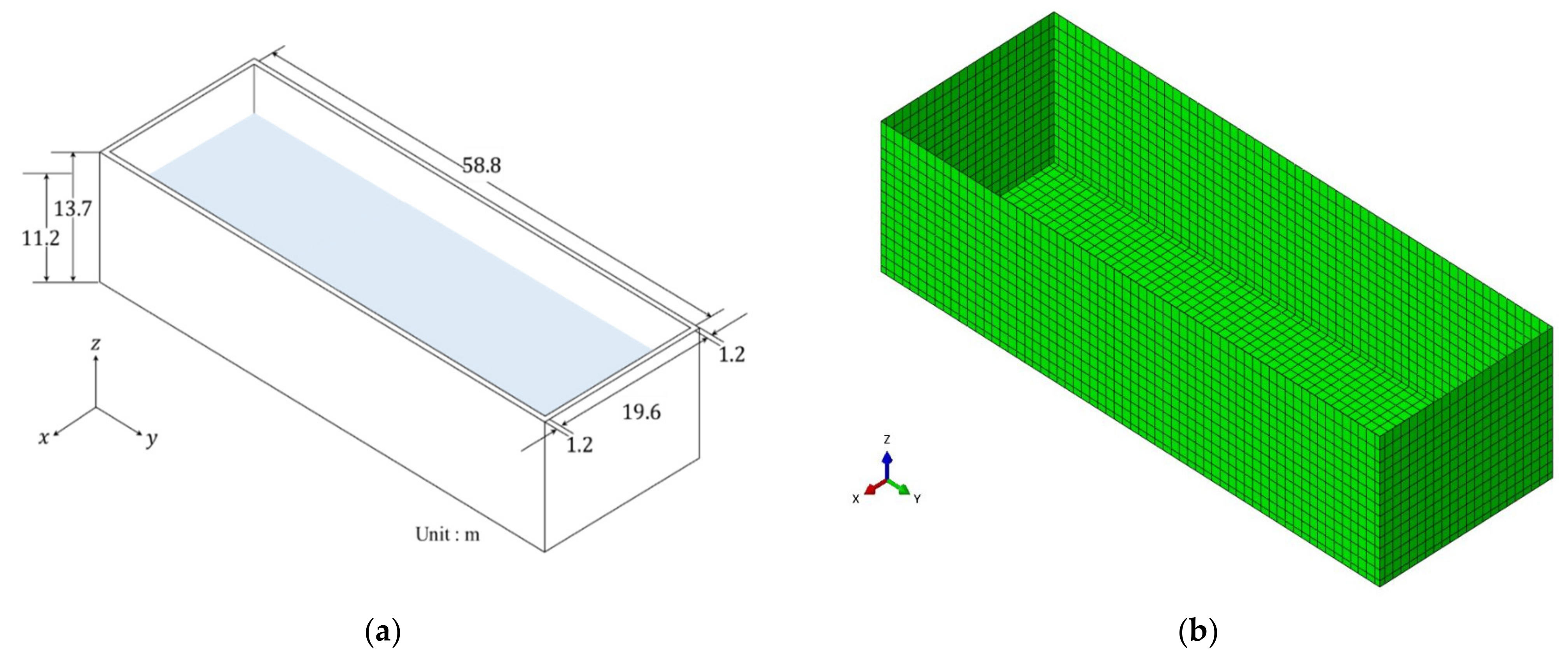
In this study, the nonlinear earthquake responses of the rectangular liquid storage tank shown in Figure 1 will be examined for various incident angles of three-directional input ground motion. The tank here is roofless and assumed to be fixed onto rigid ground, i.e., soil–structure interaction is not considered in this study. The detailed material properties of the structure and the fluid contained within it are given in Table 1. The parameters of the concrete damaged plasticity model are given in Table 2. Figure 2 shows the plasticity behavior of concrete.
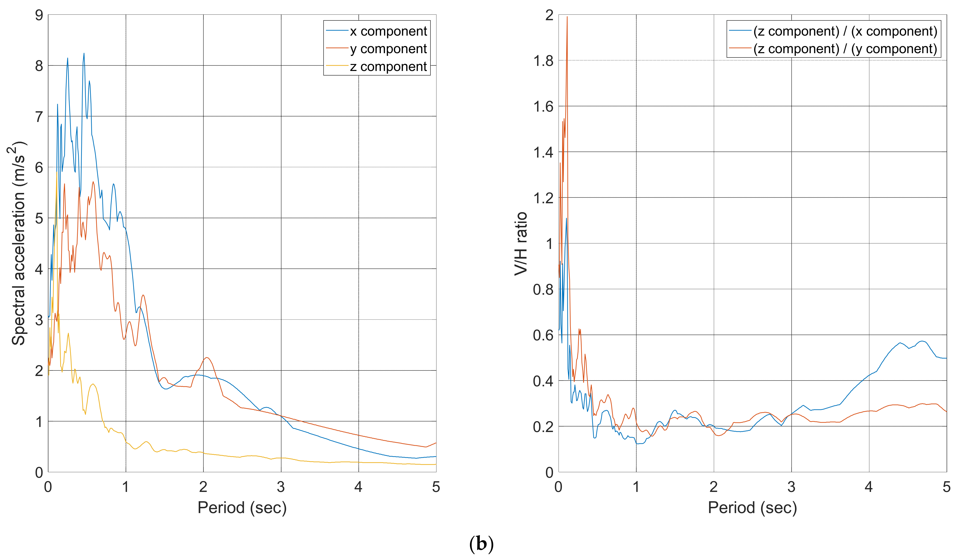
The earthquake responses of the system are obtained by the finite element analysis code ABAQUS [34]. The rectangular liquid storage tank is modeled as shown in Figure 1b. The structure is represented by the S4 elements. The *REBAR LAYER command is used to consider reinforcement. The fluid and interface elements, which are governed by Equation (4), are implemented using user-defined elements in ABAQUS. Rayleigh damping with and is employed for damping matrix in Equation (5). The three-directional El Centro earthquake ground motion in Figure 3a is considered as the input ground motion. The ground motion is the far-field motion recorded at the Imperial Valley Irrigation District station, El Centro, California during the Imperial Valley Earthquake of May 18, 1940. The response spectra for the components and the corresponding V/H ratios are also shown in Figure 3b. The V/H ratios of the peak ground accelerations are 0.6184 and 0.9069 for the x and y components, respectively.
With the aforementioned numerical model and earthquake ground motion, dynamic analyses are conducted for various incident angles of motion. The effects of static loads due to the self-weight of the structure and the hydrostatic pressure are considered before the dynamic analyses. Earthquake responses are calculated using the constant acceleration method with a time increment of 0.002 s.
3.1. Comparison of Linear and Nonlinear Analyses Results
In this subsection, the nonlinear earthquake responses of the considered system will be compared with linear responses in order to identify the effects of the nonlinearity of the material when the incident angle of the input ground motion is zero.
Figure 4 shows the time histories of the relative displacement at the highest mid-point at on the front long-sided wall. It can be observed that the material nonlinearity effects are significant for earthquake responses in the considered system. The values of the compressive damage variable from ABAQUS are zero for all calculations. This means that the inelastic responses do not develop as a result of the compressive crushing of concrete but instead develop due to tensile cracking. Figure 5 shows the deformed shapes of the structure when the maximum displacements occur at 9.46 s and 2.46 s in the nonlinear and linear analyses, respectively.
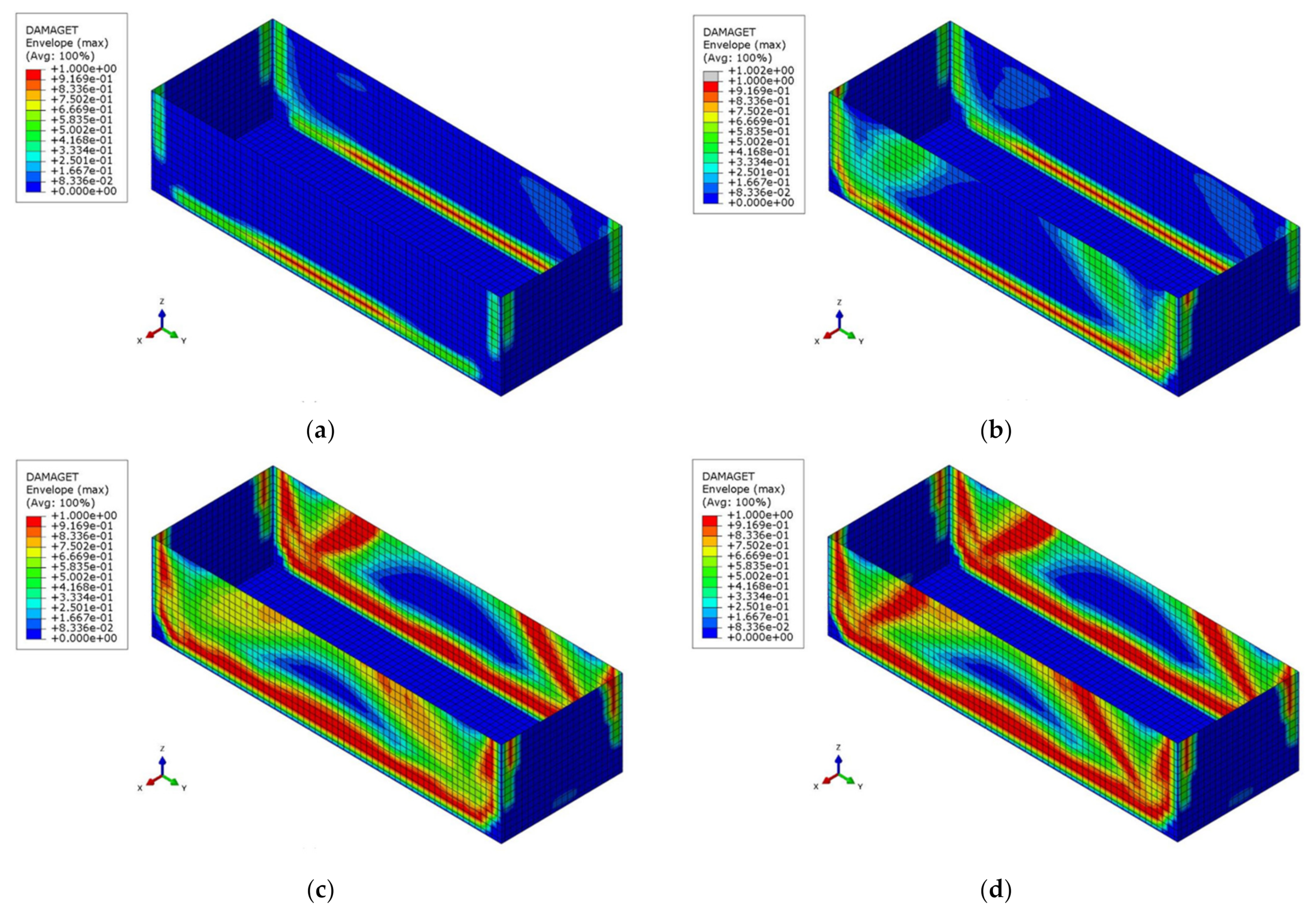
The evolution of tensile damage in the structure is examined at the times shown in Figure 4 and provided in Table 3. The evolution of the tensile damage variable from ABAQUS is shown in Figure 6. The first significant deformation of the tank occurs at 1.51 s. The tensile damage in the lower part of the long-sided walls has occurred by this time, as shown in Figure 6a. Subsequent damage occurs up to 1.91 s, as shown in Figure 6b. The damaged region is extended over the lower part of the long-sided walls and inclined damage is observed on the walls. Figure 6c show that the tensile damage spreads over the long-sided walls. The tank undergoes peak displacement at 9.46 s. The inclined damage is intensified, as shown in Figure 6d. The tensile damage does not substantially change after this time. As indicated in Figure 6, inclined cracks are observed on the long-sided walls. Reinforcing bars should be optimally placed in the areas by considering these inclined cracks.
Figure 7 shows section moments SM1, SM2, and SM3 from the nonlinear analysis at 9.46 s when the displacement shows a peak response. SM1, SM2, and SM3 are bending moments per unit width about local axes 2 and 1 and the twisting moment per unit width on the local 1–2 plane, respectively. Those from the linear analyses are shown together in the figure. It can be observed that the distributions of nonlinear section moments are very different from the linear counterparts. The distributions from the nonlinear analysis reflect the effects of inclined cracks, which cannot be considered in the linear analysis. It can be concluded from these observations that the material nonlinearity must be taken into account for a more accurate understanding of the performance of the system considered here.
The profiles of hydrodynamic pressure acting on the mid-lines of long-sided walls are provided in Figure 8 when their peak values are attained. Shown in Figure 9 are the time histories of hydrodynamic pressure at the locations of the peak responses. It can be observed that the profile and time history of the hydrodynamic pressure can be modified by the nonlinearity of the material. This modification can affect the base shear and overturning moment due to the hydrodynamic pressure and the resulting impulsive mass and its height for a simplified dynamic analysis of the liquid storage tank. For this example, the base shear and overturning moment due to the hydrodynamic pressure per unit width are correspondingly 262.2 kN and 1.472 MN m in the nonlinear analysis and 387.6 kN and 1.981 MN m in the linear analysis. The nonlinear responses are reduced by 30.7% and 25.7%, respectively. The corresponding impulsive mass is reduced by 30.7% as the base shear. The heights for the mass are 5.616 m and 5.233 m in the nonlinear and linear analyses, respectively. Because the base shear and the resulting impulsive mass in the nonlinear analysis are significantly reduced, the rigorous finite-element model, as described in this study, or a simplified mass-spring model, which considers the affected profile of the hydrodynamic pressure, must be employed for the numerical model of the contained liquid in a nonlinear dynamic analysis.
Because the hydrodynamic pressure from the sloshing of the liquid in a tank can damage the tank walls and roof, the sloshing height must be calculated when the earthquake responses of a liquid storage tank are examined. In order to examine the effects of the material nonlinearity on the sloshing, the time history of the sloshing height at (9.8 m, 29.4 m, 12.4 m) on the free surface is calculated and compared to that from the elastic analysis in Figure 10. It can be observed that the two time histories are nearly identical. This is because the convective mode of the fluid motion is adequately separated from the corresponding impulsive mode. Therefore, the material nonlinearity in the structure has negligible effects on the sloshing height, as shown in Figure 10. The sloshing height from the linear analysis after the earthquake is also shown in Figure 10. It can be observed that the response has its maximum at 106.07 s after the earthquake. Because the damping for sloshing is negligible, the maximum response is generated at the free-vibration phase. Therefore, the earthquake responses of sloshing height must be determined to verify the freeboard of a tank even after an earthquake’s ground motion stops.
In the past earthquakes, damage in building structures due to a high level of vertical acceleration was observed [35]. Therefore, the effects of combined vertical and horizontal seismic action have been studied, especially in near-fault ground motions [35,36,37,38]. In this study, the effects are also examined for the considered rectangular liquid storage tank. The earthquake responses of the system are calculated with only the horizontal components and in Figure 3 and compared with those with the three components. Figure 11 shows the time histories of the relative displacement at the highest mid-point at on the front long-sided wall.
Figure 12 presents the evolution of the tensile damage variable . It can be observed that the effects of the vertical component of input ground motion are not significant for the considered system. Because the hydrodynamic pressure applied on the tank wall is principally influenced by the horizontal components, the effects of the vertical component can be insignificant. However, it should be noted that only one far-field ground motion is considered in this study. The effects of the vertical component are larger in a near-fault ground motion than those in a far-field motion [36,37,38]. Therefore, the effects on a rectangular liquid storage tank must be considered for a variety of far-field and near-fault ground motions.
3.2. Nonlinear Dynamic Responses to a Three-Directional Earthquake Ground Motion
It was observed that the elastic earthquake responses of rectangular liquid storage tanks are influenced significantly by the incident angles of bi-directional input ground motion [27]. Therefore, the effects of incident angles on the inelastic earthquake responses of the fluid–structure interaction system considered here will be examined with three-directional input ground motion. To evaluate the effects of the incident angle of earthquake ground motion, the three-directional motion in Figure 3 is rotated. In order to define a new coordinate system, the original xyz system is rotated by an angle of as shown in Figure 13. The components , , and in Figure 3 are applied in the , , and directions. The components , , and of input ground motion for the incident angle can then be determined as follows:
The values considered here for the incident angle range from 0° to 170° in increments of 10°. The variations of the maximum displacement of the structure, the maximum hydrodynamic pressure, and the maximum sloshing height are shown in Figure 14a,c, respectively. It can be observed that the earthquake responses are significantly affected by the incident angle. However, no consistent trend can be observed in the responses. Therefore, it is necessary to consider the directionality of the input ground motion for reliable predictions of the earthquake responses of this system.
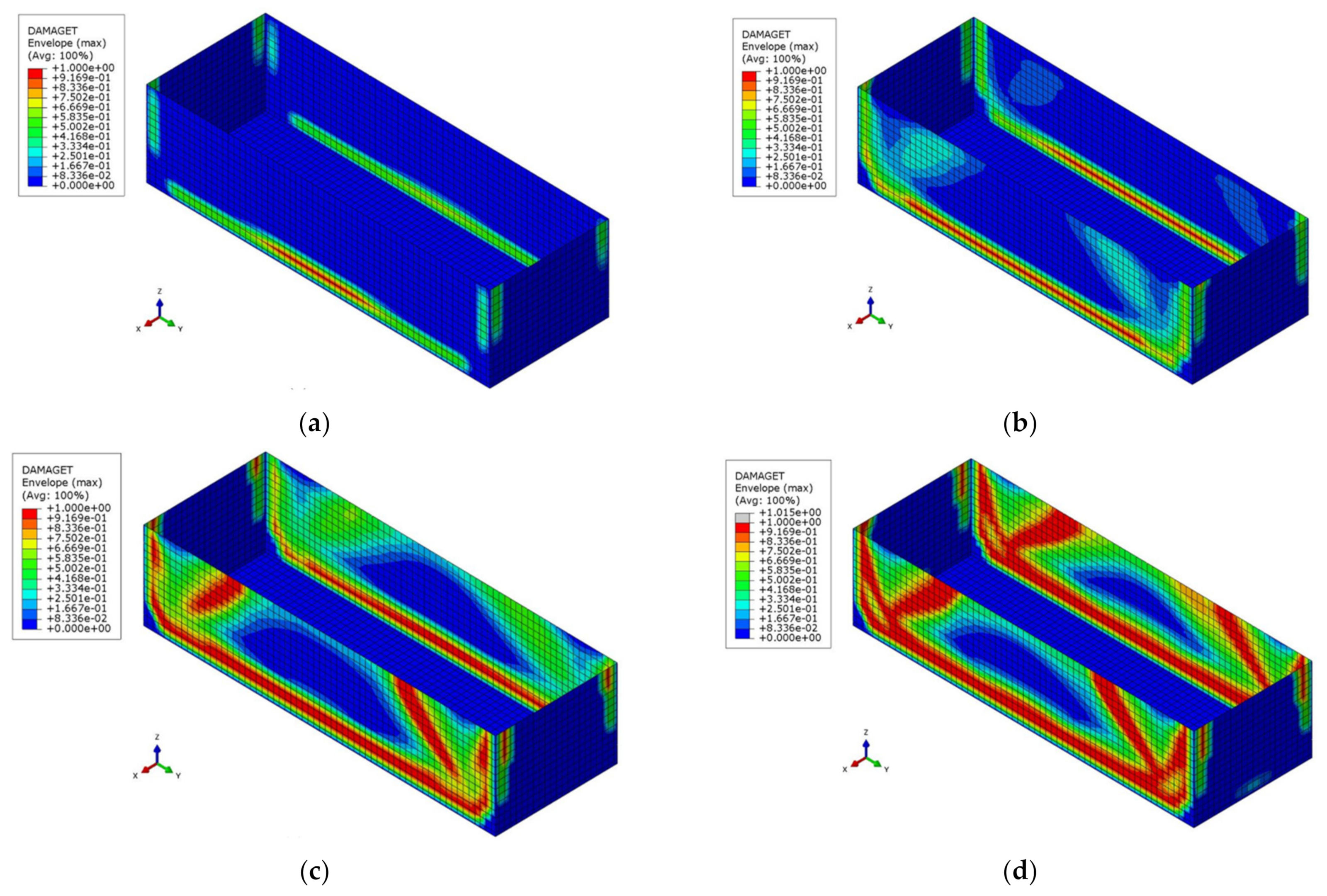
It can be observed in Figure 14a–c that the responses are significantly affected at the incident angles of 50°, 100°, and 140°. Therefore, detailed examinations of the responses at these angles are provided. The time histories for displacement are shown in Figure 15. Similar to when the incident angle is zero, several times in Table 3 are chosen to examine the evolution of the tensile damage variable . It can be observed that Times A and B are similar for the considered incident angles. However, Times C and D are very different for these cases. These different times mean that the earthquake responses of a rectangular liquid storage tank are influenced significantly by the incident angle of earthquake ground motions.
The evolution of the tensile damage variable can be observed in Figure 16, Figure 17 and Figure 18 for the corresponding incident angles. The evolution outcomes of the damage-related variables show very similar patterns in the analyses. However, it should be noted that at Times C and D, at which one long-sided wall or both walls are damaged, are different in these analyses. It can be concluded from these observations that a rigorous inelastic analysis must be considered to predict the earthquake responses of a rectangular liquid storage tank accurately during bi-/three-directional earthquake ground motions.
The profiles of the hydrodynamic pressure on the mid-line of the long sided-walls are provided in Figure 8 for the considered incident angles. It can be observed that the distributions are influenced significantly by the incident angles of the input ground motion. The base shear and overturning moment due to the hydrodynamic pressure per unit width are also influenced, as shown in Figure 14d,e. When compared to the values of 387.6 kN and 1.981 MN m from the elastic analysis, the responses are reduced by up to 42.2 % and 47.9%, respectively, when the incident angle is 140°. Because the base shear is affected by the material nonlinearity and the incident angle of the input ground motion, the resulting impulsive mass is also influenced in the same way. The affected base shear and overturning moment cause a change of the impulsive-mass height, as shown in Figure 14f. It can be observed in Figure 14d,f that the impulsive mass and corresponding height are both affected significantly by the material nonlinearity and the incident angle of the input ground motion. Therefore, these factors must be rigorously considered for an accurate estimation of nonlinear earthquake responses of a rectangular liquid storage tank. They must also be reflected thoroughly when establishing a mass-spring analogy model for a simplified nonlinear dynamic analysis of such a system in order to obtain conservative results irrespective of the incident angle of the earthquake ground motion.
The responses of sloshing heights to the considered incident angles are shown in Figure 19. As observed in Figure 14c, the sloshing height can be affected significantly by the incident angle of the input ground motion. Therefore, the maximum sloshing height for a seismic design of a rectangular liquid tank can be estimated by considering the directionality of earthquake ground motions.
4. Discussion
In this study, the dynamic responses of a rectangular liquid storage subjected to a three-directional earthquake ground motion were examined. The effects of nonlinearity in structural material and those of incidence angle of an input ground motion were considered in the examination. In order to extend the applicable area of the numerical approach in the present study, the approach can be improved in future studies as described below.
In this study, the earthquake responses of a concrete rectangular liquid storage tank on the surface of rigid soil were investigated. However, steel can be used for the structural material of tank. The numerical approach in this study can be applied to a steel tank. In the case, a proper plastic model for steel should be considered. For example, a variety of plasticity models are available for metal in ABAQUS [34]. A proper plasticity model can be chosen among the models and employed for dynamic analysis of a steel tank.
The effects of soil–structure interaction (SSI) were not considered in this study. It should be noted that the effects cannot be ignored when the system is installed and/or embedded in flexible soil [18,39]. Therefore, the effects of SSI must be considered in future studies. The latest approaches to consider the effects of linear and nonlinear SSI can be found in the ASCE standard [40].
In this study, only water was considered for the contained liquid. However, various fluids, such as water, oil, LNG and others, can be stored in a tank. The hydrodynamic pressure in a specific fluid can be calculated in the same way in Section 2 with a specific value for the density . The tank structure can show different dynamic behavior depending on the density. However, it should be noted that the density of water is usually larger than those of other fluids. Therefore, the case of water can be the conservative one. If a fluid with a larger density than water is considered, the dynamic responses of a liquid storage tank must be examined rigorously with the numerical approach in this study.
Because building structures was damaged by a high level of vertical acceleration in the past earthquakes, the effects of combined vertical and horizontal seismic action have been studied, especially in near-fault ground motions [35,36,37,38]. In this study, the effects were examined and observed insignificant for the considered rectangular liquid storage tank. However, only one far-field record of earthquake ground motion was considered in this study. Therefore, the effects of the vertical component on a rectangular liquid storage tank must be considered for a variety of far-field and near-fault ground motions in future studies.
5. Conclusions
Liquid storage tanks are an essential category in the infrastructure of our modern society and industries. Damage to a liquid storage tank can be a major concern because it can lead to serious social and economic losses. Therefore, many researchers have investigated the dynamic responses of liquid storage tanks. Many studies have sought to investigate the fluid–structure interaction effects on the seismic performance of a liquid storage tank. However, the effects of fluid–structure interaction with the nonlinearity of the material have not been widely considered in seismic performance assessment, while determinations of the maximum hydrodynamic pressures induced by earthquake ground motion require, in principle, the use of a nonlinear dynamic (time-history) analysis, as specified in Eurocode 8 [25].
In this study, the earthquake responses of a concrete rectangular liquid storage on the surface of rigid soil were investigated with material nonlinearity taken into consideration. The material nonlinearity in concrete was considered using the concrete damage plasticity model. Because the rectangular structure has geometric asymmetry and given that the corresponding earthquake responses depend on the incident angle of three-directional earthquake ground motion, directional effects were examined in this study. From the dynamic analyses of a rectangular liquid storage tank subjected to three-directional earthquake ground motion, the following can be concluded:
- The effects of material nonlinearity are significant when considering the earthquake responses of the system considered here. The displacement increases significantly due to the material nonlinearity. With the increased displacement, inclined cracks, which are typical for concrete structures such as slabs and plates, arise on the long-sided walls. The evolution of the tensile damage reflects the inclined cracks. The distributions of the section moments are also influenced by the inclined cracks. Reinforcing bars should be optimally placed in these areas after taking the inclined cracks into account.
- The hydrodynamic pressure can be reduced significantly by the material nonlinearity. This reduction can also modify the base shear and overturning moment due to the hydrodynamic pressure and the resulting impulsive mass and its height in a simplified dynamic analysis of a liquid storage tank. Therefore, the material nonlinearity should be taken into account to ensure more accurate predictions of the hydrodynamic pressure applied to such a structure.
- The time history of the sloshing height from the nonlinear analysis is nearly identical to that from the linear analysis. This is due to the fact that the convective mode of the fluid motion is adequately separated from its impulsive mode. Therefore, the material nonlinearity in the structure has negligible effects on the sloshing height.
- The earthquake responses of a rectangular liquid storage tank are affected significantly by the incident angle of the earthquake ground motion. However, no consistent trend was noted in the responses of the displacement, hydrodynamic pressure, or sloshing height. Therefore, it is necessary to consider the directionality of the input ground motion for reliable predictions of the earthquake responses of such a system.
- The evolution of the tensile damage shows very similar patterns in the analyses at various incident angles of earthquake ground motion. However, it should be noted that the times at which one or both long-sided walls become damaged strongly depend on the incident angle. It can be concluded from these observations that a rigorous inelastic analysis must be considered to predict accurately the earthquake responses of a rectangular liquid storage tank.
- The profiles of the hydrodynamic pressure are significantly influenced by the incident angle of the input ground motion. The base shear and overturning moment due to the hydrodynamic pressure and the resulting impulsive mass and corresponding height of the liquid storage tank are also affected by the incident angle. Therefore, a simplified spring-mass analogy model should be established after considering the dependence in order to ensure conservative results irrespective of the incident angle of the earthquake ground motion.
- The time history of the sloshing height can be affected significantly by the incident angle of the input ground motion. Therefore, the peak value should be estimated with the directionality of earthquake ground motions considered.
Author Contributions
Conceptualization, J.H.L.; methodology, J.H.L.; validation, C.B.L. and J.H.L.; formal analysis, C.B.L.; investigation, C.B.L.; data curation, C.B.L.; writing—original draft preparation, C.B.L.; writing—review and editing, J.H.L.; visualization, C.B.L.; supervision, J.H.L.; project administration, J.H.L.; funding acquisition, J.H.L. All authors have read and agreed to the published version of the manuscript.
Funding
This research received no external funding.
Institutional Review Board Statement
Not applicable.
Informed Consent Statement
Not applicable.
Data Availability Statement
The data presented in this study are available on request from the corresponding author.
Acknowledgments
This work was supported by the Korea Environment Industry & Technology Institute (KEITI) through the Environmental R&D Project on the Disaster Prevention of Environmental Facilities Program, funded by Korea’s Ministry of Environment (MOE) (2019002850003). This work was supported by the National Research Foundation of Korea (NRF) grant funded by the Korean government (MSIT: Ministry of Science and ICT) (No.2017M2A8A401504221).
Conflicts of Interest
The authors declare no conflict of interest.
References
- Rawat, A.; Mittal, V.; Chakracborty, T.; Matsgar, V. Earthquake induced sloshing and hydrodynamic pressures in rigid liquid storage tanks analyzed by coupled acoustic-structural and Euler LaGrange methods. Thin Walled Struct. 2019, 134, 333–346. [Google Scholar] [CrossRef]
- Housner, G.W. Dynamic pressure on accelerated fluid containers. Bull. Seismol. Soc. Am. 1957, 47, 15–35. [Google Scholar]
- Housner, G.W. Behavior of structures during earthquakes. J. Eng. Mech. Div. 1959, 85, 109–130. [Google Scholar] [CrossRef]
- Housner, G.W. The dynamic behaviour of water tanks. Bull. Seismol. Soc. Am. 1963, 53, 381–387. [Google Scholar]
- Veletsos, A.S.; Yang, J.Y. Dynamics of fixed-base liquid storage tanks. Proceedings of U.S.-Japan Seminar for Earthquake Engineering Research with Emphasis on Lifeline Systems, Tokyo, Japan, 8–12 November 1976; pp. 317–341. [Google Scholar]
- Veletsos, A.S.; Tang, Y.; Tang, H.T. Dynamic responses of flexible supported liquid storage tanks. ASCE J. Struct. Eng. 1992, 118, 264–283. [Google Scholar] [CrossRef]
- Haroun, M.A.; Housner, G.W. Dynamic analyses of liquid storage tanks. In Proceedings of the Seventh World Conference on Earthquake Engineering, Istanbul, Turkey, 8–13 September 1980; Volume 8, pp. 431–438. [Google Scholar]
- Haroun, M.A.; Housner, G.W. Seismic design of liquid storage tanks. J. Tech. Counc. ASCE 1981, 107, 191–207. [Google Scholar] [CrossRef]
- Veletsos, A.S.; Tang, Y. Rocking response of liquid storage tanks. J. Eng. Mech. 1987, 113, 1774–1792. [Google Scholar] [CrossRef]
- Haroun, M.A. Vibration studies and tests of liquid storage tanks. Earthq. Eng. Struct. Dyn. 1983, 11, 176–206. [Google Scholar] [CrossRef]
- Kim, J.K.; Koh, H.M.; Kwahk, I.J. Dynamic response of rectangular flexible fluid containers. J. Eng. Mech. 1996, 122, 807–817. [Google Scholar] [CrossRef]
- Kianoush, M.R.; Chen, J.Z. Effect of vertical acceleration on response of concrete rectangular liquid storage tanks. Eng. Struct. 2006, 28, 704–715. [Google Scholar] [CrossRef]
- Kianoush, M.R.; Chen, J.Z. Generalized SDOF system for seismic analysis of concrete rectangular liquid storage tanks. Eng. Struct. 2009, 31, 2426–2435. [Google Scholar]
- Liu, W.K.; Lam, D. Nonlinear analysis of liquid-filled tank. J. Eng. Mech. 1983, 109, 1344–1357. [Google Scholar] [CrossRef]
- Park, J.H.; Koh, H.M.; Kim, J. Fluid–structure interaction analysis by a coupled boundary element–finite element method in time domain. In Boundary Element Technology VII; Brebbia, C.A., Ingber, M.S., Eds.; Springer: Dordrecht, The Netherlands, 1992; pp. 227–243. [Google Scholar]
- Koh, H.M.; Kim, J.K.; Park, J.H. Fluid-structure interaction analysis of 3-D rectangular tanks by a variationally coupled BEM-FEM and comparison with test results. Earthq. Eng. Struct. Dyn. 1998, 27, 109–124. [Google Scholar] [CrossRef]
- Wunderlich, W.; Seiler, C. Nonlinear treatment of liquid-filled storage tanks under earthquake excitation by a quasistatic approach. Comput. Struct. 2000, 78, 385–395. [Google Scholar] [CrossRef]
- Kianoush, M.R.; Ghaemmaghami, A.R. The effect of earthquake frequency content on the seismic behavior of concrete rectangular liquid tanks using the finite element method incorporating soil–structure interaction. Eng. Struct. 2011, 33, 2186–2200. [Google Scholar] [CrossRef]
- Spritzer, J.M.; Guzey, S. Nonlinear numerical evaluation of large open-top aboveground steel welded liquid storage tanks excited by seismic loads. Thin Walled Struct. 2017, 119, 662–676. [Google Scholar] [CrossRef]
- Chen, W.; Haroun, M.A.; Liu, F. Large amplitude liquid sloshing in seismically excited tanks. Earthq. Eng. Struct. Dyn. 1996, 25, 653–669. [Google Scholar] [CrossRef]
- Celebi, M.S.; Akyildiz, H. Nonlinear modeling of liquid sloshing in a moving rectangular tank. Ocean Eng. 2002, 29, 1527–1553. [Google Scholar] [CrossRef]
- Akyildiz, H.; Ünal, N.E. Sloshing in a three-dimensional rectangular tank: Numerical simulation and experimental validation. Ocean. Eng. 2006, 33, 2135–2149. [Google Scholar] [CrossRef]
- Goudarzi, M.A.; Sabbagh-Yazdi, S.R. Investigation of nonlinear sloshing effects in seismically excited tanks. Soil Dyn. Earthq. Eng. 2012, 43, 355–365. [Google Scholar] [CrossRef]
- Moslemi, M.; Farzin, A.; Kianoush, M.R. Nonlinear sloshing response of liquid-filled rectangular concrete tanks under seismic excitation. Eng. Struct. 2019, 188, 564–577. [Google Scholar] [CrossRef]
- Comité Européen de Normalisation (CEN). Eurocode 8—Design of Structures for Earthquake Resistance—Part 4: Silos, Tanks and Pipelines; EN 1998-4:2006; CEN: Brussels, Belgium, 2006. [Google Scholar]
- Hafezolghorani, M.; Hehazi, F.; Vaghei, R. Simplified damage plasticity model for concrete. Struct. Eng. Int. 2017, 27, 68–78. [Google Scholar] [CrossRef]
- Lee, J.H.; Lee, S.H. Characteristics of earthquake response of rectangular liquid storage tanks subjected to bi-directional horizontal ground motions. Comput. Struct. Eng. Inst. Korea 2020, 33, 45–53. (In Korean) [Google Scholar] [CrossRef]
- Cook, R.D.; Malkus, D.S.; Plesha, M.E.; Witt, R.J. Concepts and Applications of Finite Element Analysis, 4th ed.; John Wiley & Sons. Inc.: Hoboken, NJ, USA, 2002. [Google Scholar]
- Lubliner, J.; Oliber, J.; Oller, S.; Oñate, E. A plastic-damage model for concrete. Int. J. Solids Struct. 1989, 25, 299–326. [Google Scholar] [CrossRef]
- Lee, J.H.; Fenves, G.L. A plastic-damage concrete model for earthquake analysis of dams. Earthq. Eng. Struct. Dyn. 1998, 27, 937–956. [Google Scholar] [CrossRef]
- Lee, J.H.; Fenves, G.L. A return-mapping algorithm for plastic-damage models: 3-D and plane stress formulation. Int. J. Num. Methods Eng. 2001, 50, 487–506. [Google Scholar] [CrossRef]
- Mokhatar, S.N.; Abdullah, R. Computational analysis of reinforced concrete slabs subjected to impact loads. Int. J. Integr. Eng. 2012, 4, 70–76. [Google Scholar]
- Omidi, O.; Valliappan, S.; Lotfi, V. Seismic cracking of concrete gravity dams by plastic-damage model using different damping mechanisms. Finite Elements Anal. Des. 2013, 63, 80–97. [Google Scholar] [CrossRef]
- ABAQUS. ABAQUS Documentation; Dassault Systèmes Simulia Corp.: Providence, RI, USA, 2019. [Google Scholar]
- Collier, C.J.; Elnashai, A.S. A procedure for combining vertical and horizontal seismic action Effects. J. Earthq. Eng. 2008, 5, 521–539. [Google Scholar] [CrossRef]
- Di Sarno, L.; Elnashai, A.S.; Manfredi, G. Assessment of RC columns subjected to horizontal and vertical ground motions recorded during the 2009 L’Aquila (Italy) earthquake. Eng. Struct. 2011, 33, 1514–1535. [Google Scholar] [CrossRef]
- Di Michele, F.; Cantagallo, C.; Spacone, E. Effects of the vertical seismic component on seismic performance of an unreinforced masonry structures. Bull. Eng. 2020, 18, 1635–1656. [Google Scholar] [CrossRef]
- Chieffo, N.; Formisano, A.; Mosoarca, M.; Lourenço, P.B. Seismic vulnerability assessment of a romanian historical masonry building under near-source earthquake. In Proceedings of the XI International Conference on Structural Dynamic (EURODYN 2020), Athens, Greece, 23–26 November 2020; pp. 4957–4971. [Google Scholar]
- Lee, J.H.; Cho, J.R.; Han, S.W. Time-domain earthquake response analysis of rectangular liquid storage tank considering fluid-structure-soil interaction. Comput. Struct. Eng. Inst. Korea 2020, 33, 383–390. (In Korean) [Google Scholar] [CrossRef]
- American Society of Civil Engineers. Seismic Analysis of Safety-Related Nuclear Structures, ASCE/SEI 4-16; American Society of Civil Engineers: Reston, VA, USA, 2017. [Google Scholar]
Figure 1.
Rectangular liquid storage tank: (a) schematic view; (b) finite element model.

Figure 2.
Inelastic tensile behavior of concrete: (a) tensile stress–strain curve; (b) tensile damage model.
Figure 2.
Inelastic tensile behavior of concrete: (a) tensile stress–strain curve; (b) tensile damage model.

Figure 3.
Input ground motion: (a) Time histories of the components , , and ; (b) response spectra and the corresponding V/H ratios.
Figure 3.
Input ground motion: (a) Time histories of the components , , and ; (b) response spectra and the corresponding V/H ratios.


Figure 4.
Relative displacement when the incident angle of the input ground motion is zero.

Figure 5.
Deformed shapes of the tank structure: (a) nonlinear analysis; (b) linear analysis.

Figure 6.
Tensile damage variable when the incident angle of the input ground motion is zero: (a) 1.51 s; (b) 1.91 s; (c) 2.60 s; (d) 9.46 s.
Figure 6.
Tensile damage variable when the incident angle of the input ground motion is zero: (a) 1.51 s; (b) 1.91 s; (c) 2.60 s; (d) 9.46 s.

Figure 7.
Section moments of the tank structure: (a) SM1 from nonlinear analysis; (b) SM1 from linear analysis; (c) SM2 from nonlinear analysis; (d) SM2 from linear analysis; (e) SM3 from nonlinear analysis; (f) SM3 from linear analysis.
Figure 7.
Section moments of the tank structure: (a) SM1 from nonlinear analysis; (b) SM1 from linear analysis; (c) SM2 from nonlinear analysis; (d) SM2 from linear analysis; (e) SM3 from nonlinear analysis; (f) SM3 from linear analysis.


Figure 8.
Hydrodynamic pressure distribution.

Figure 9.
Time histories of hydrodynamic pressure when the incident angle of the input ground motion is zero: (a) Nonlinear analysis; (b) Linear analysis.
Figure 9.
Time histories of hydrodynamic pressure when the incident angle of the input ground motion is zero: (a) Nonlinear analysis; (b) Linear analysis.

Figure 10.
Sloshing heights when the incident angle of the input ground motion is zero.

Figure 11.
Relative displacement when the horizontal components of the input ground motion are considered only.
Figure 11.
Relative displacement when the horizontal components of the input ground motion are considered only.

Figure 12.
Tensile damage variable when the horizontal components of the input ground motion are considered only: (a) 1.51 s; (b) 1.91 s; (c) 2.60 s; (d) 9.46 s.
Figure 12.
Tensile damage variable when the horizontal components of the input ground motion are considered only: (a) 1.51 s; (b) 1.91 s; (c) 2.60 s; (d) 9.46 s.

Figure 13.
coordinate system for the incident angle .

Figure 14.
Variations of earthquake responses according to the incident angle of an input ground motion: (a) relative displacement; (b) hydrodynamic pressure; (c) sloshing height; (d) base shear; (e) base overturning moment; (f) height for impulsive mass.
Figure 14.
Variations of earthquake responses according to the incident angle of an input ground motion: (a) relative displacement; (b) hydrodynamic pressure; (c) sloshing height; (d) base shear; (e) base overturning moment; (f) height for impulsive mass.

Figure 15.
Relative displacement of the tank structure: (a) incident angle of 50°; (b) incident angle of 100°; (c) incident angle of 140°.
Figure 15.
Relative displacement of the tank structure: (a) incident angle of 50°; (b) incident angle of 100°; (c) incident angle of 140°.

Figure 16.
Tensile damage variable when the incident angle of the input ground motion is 50°: (a) 1.46 s; (b) 2.37 s; (c) 2.69 s; (d) 12.23 s.
Figure 16.
Tensile damage variable when the incident angle of the input ground motion is 50°: (a) 1.46 s; (b) 2.37 s; (c) 2.69 s; (d) 12.23 s.

Figure 17.
Tensile damage variable when the incident angle of the input ground motion is 100°: (a) 1.30 s; (b) 2.15 s; (c) 8.71 s; (d) 25.53 s.
Figure 17.
Tensile damage variable when the incident angle of the input ground motion is 100°: (a) 1.30 s; (b) 2.15 s; (c) 8.71 s; (d) 25.53 s.

Figure 18.
Tensile damage variable when the incident angle of the input ground motion is 140°: (a) 1.20 s; (b) 1.75 s; (c) 2.30 s; (d) 24.61 s.
Figure 18.
Tensile damage variable when the incident angle of the input ground motion is 140°: (a) 1.20 s; (b) 1.75 s; (c) 2.30 s; (d) 24.61 s.

Figure 19.
Sloshing heights at the free surface.


Table 1.
Material properties of a rectangular liquid tank.
| Property | Value | ||
|---|---|---|---|
| Structure | Concrete | Density | 2300 kg/m3 |
| Poisson’s Ratio | 0.17 | ||
| Young’s Modulus | 38.527 GPa | ||
| Compressive yield stress | 13.0 MPa | ||
| Compressive ultimate strength | 24.1 MPa | ||
| Inelastic strain at compressive ultimate strength | 0.001 | ||
| Tension failure strength | 2.9 MPa | ||
| Inelastic tensile behavior | Table 2 | ||
| Dilation angle | 36.31° | ||
| Flow potential eccentricity | 0.1 | ||
| Ratio of initial equibiaxial and uniaxial compressive yield stresses | 1.16 | ||
| Parameter [29] or [34] | 0.667 | ||
| Viscosity parameter | 0 | ||
| Reinforcement | Cross-sectional area | 0.00306 m2 | |
| Young’s modulus | 2.0 GPa | ||
| Plastic modulus | 0.345 GPa | ||
| Ratio of volume of steel to that of concrete | 1.6576 × 10⁻³ | ||
| Liquid | Density | 1000 kg/m3 | |
Table 2.
Inelastic tensile behavior of concrete.
| Cracking Strain | Tensile Stress (MPa) | Damage Parameter |
|---|---|---|
| 0 | 2.9 | 0 |
| 6.6185 × 10⁻⁵ | 1.9439 | 0.3812 |
| 1.2286 × 10⁻⁵ | 1.3031 | 0.6171 |
| 1.7343 × 10⁻⁵ | 0.8735 | 0.7631 |
| 2.2019 × 10⁻⁴ | 0.5855 | 0.8534 |
| 2.2647 × 10⁻⁴ | 0.3925 | 0.9093 |
| 3.0808 × 10⁻⁴ | 0.2631 | 0.9439 |
| 3.5105 × 10⁻⁴ | 0.1763 | 0.9653 |
| 3.9414 × 10⁻⁴ | 0.1182 | 0.9785 |
| 4.3774 × 10⁻⁴ | 0.0792 | 0.9867 |
| 4.8217 × 10⁻⁴ | 0.0531 | 0.9918 |
Table 3.
Times at which the evolution of tensile damage is examined.
| Incident Angle | Time A | Time B | Time C | Time D |
|---|---|---|---|---|
| 0° | 1.51 s | 1.91 s | 2.60 s | 9.46 s |
| 50° | 1.46 s | 2.37 s | 2.69 s | 12.23 s |
| 100° | 1.30 s | 2.15 s | 8.71 s | 25.53 s |
| 150° | 1.20 s | 1.75 s | 2.30 s | 24.61 s |
Publisher’s Note: MDPI stays neutral with regard to jurisdictional claims in published maps and institutional affiliations. |
© 2021 by the authors. Licensee MDPI, Basel, Switzerland. This article is an open access article distributed under the terms and conditions of the Creative Commons Attribution (CC BY) license (https://creativecommons.org/licenses/by/4.0/).
Share and Cite
MDPI and ACS Style
Lee, C.-B.; Lee, J.-H. Nonlinear Dynamic Response of a Concrete Rectangular Liquid Storage Tank on Rigid Soil Subjected to Three-Directional Ground Motion. Appl. Sci. 2021, 11, 4688. https://0-doi-org.brum.beds.ac.uk/10.3390/app11104688
AMA Style
Lee C-B, Lee J-H. Nonlinear Dynamic Response of a Concrete Rectangular Liquid Storage Tank on Rigid Soil Subjected to Three-Directional Ground Motion. Applied Sciences. 2021; 11(10):4688. https://0-doi-org.brum.beds.ac.uk/10.3390/app11104688
Chicago/Turabian StyleLee, Chae-Been, and Jin-Ho Lee. 2021. "Nonlinear Dynamic Response of a Concrete Rectangular Liquid Storage Tank on Rigid Soil Subjected to Three-Directional Ground Motion" Applied Sciences 11, no. 10: 4688. https://0-doi-org.brum.beds.ac.uk/10.3390/app11104688
Note that from the first issue of 2016, this journal uses article numbers instead of page numbers. See further details here.