
Effect of Micro-Silica Addition into Electric Arc Furnace Steel Slag Eco-Efficient Concrete


1
LADICIM—Laboratory of Materials Science and Engineering, University of Cantabria, E.T.S. de Ingenieros de Caminos, Canales y Puertos, Av./Los Castros 44, 39005 Santander, Spain
2
Department of Civil Engineering, Isfahan University of Technology, Isfahan 84156-83111, Iran
*
Author to whom correspondence should be addressed.
Appl. Sci. 2021, 11(11), 4893; https://0-doi-org.brum.beds.ac.uk/10.3390/app11114893
Submission received: 8 April 2021
/
Revised: 21 May 2021
/
Accepted: 21 May 2021
/
Published: 26 May 2021
(This article belongs to the Special Issue Structural Behaviour of Concrete Waste Materials)
Abstract
:Concrete produced from electric arc furnace steel slag aggregates is one of the items that is highly regarded due to its strength, environmental friendliness and cost-effectiveness. Despite the growing interest in using this type of concrete, there are still doubts about the mix proportions and addition effects of electric arc furnace steel slags. In this paper, the performance of replacing natural aggregates by electric arc furnace steel slags aggregate is comprehensively investigated and its effect on mechanical properties is analysed. The relationship between the percentage of replacement of natural aggregate using electric arc furnace steel slags aggregate in two parts of coarse aggregate and fine-grained aggregate and the effect of each of these parts on mechanical properties in concrete is investigated, which may identify the optimal mix proportions of each aggregate that help to improve the strength of the eco efficient concrete using electric arc furnace steel slags.
1. Introduction
With the growth of population and the expansion of construction and industry activities, the demand for the use of materials such as steel and concrete is increasing. This has led to an increase in the generation of greenhouse gases and wastes from these two sectors. Therefore, the reduction of emissions and the use of recycled materials are very important. Helping to conserve irreplaceable natural resources, reducing environmental pollution and reducing the energy spent during the production of new materials, are among the goals for the future engineering. One of the materials that can have a huge impact on this is slag. Slag is an artificial and lateral product, which occurs when iron isolates in iron melting furnaces from impurities in iron ore. Slag is a combination of silicate and metallic oxides that remain after the cooler of the gross material. This combination is applied after a solid form in a variety of uses, which are the ceremonies of refractory and fertilizer and railway wool materials and road subgroup materials, asphalt and concrete materials [1]. Steel furnace slag (SFS) is a type of slag that is a product of iron production. This material is produced in both forms, basic oxygen furnace (BOF) that is the product of converting iron to steel, which is also known as Linz–Donawitz (LD), or LD-converter slag and electric arc furnace (EAF) that is melting scrap steel product [2].
With regard to the possibility of valorising slag as aggregate, EAFS aggregates or slags from metal furnaces have an important role because in recent decades, the steel industry in Europe has advanced in the technology of making steel [2,3]. EAF technology is used in about 30% of European carbon and low alloy steel production. In Spain alone, approximately 70% of all steel is produced in arc furnaces (10 t/year of EAF steel), which represents about 15% of all European EAF steel (67 t/year) [4,5,6]. Slags are generally classified into two categories: Blast furnace (BF) slag and steelmaking (SM) slag. EAF slag, one of the SM slags which is extracted from the recycling of electric arc furnace waste. There are a large number of studies that propose to use this waste as recycled aggregates for concrete; avoiding this makes use of natural resources to produce aggregate for structural purposes [7,8]. EAFS has the appearance of black stone, which is very dense compared to other natural aggregates, usually with rough texture and angular shape [9]. Iron, calcium and silicon oxide are the main components of electric furnace slag, while the concentration of other compounds (magnesium, aluminium, manganese) is lower [10]. Since EAFS, such as limestone aggregate, have good resistance to compressive strength, researchers have tried to use and replace the ordinary aggregate using them [11].
Some studies show that this aggregate has been successful against penetration sulfites and Chlorides as well as gaining compressive strength [12,13]. Moreover, research is made on its properties, including cases such as production of concrete sleepers, use in ballast, use in foundations and substrates, as well as aggregates in concrete to improve the mechanical properties of concrete [14,15,16,17], use in concrete as aggregate [18] and slag bricks and slag ceramic tiles [16]. However, at high temperatures, concrete with natural aggregates performs better than concrete with EAFS aggregates, which may be due to the presence of iron compounds in EAFS aggregates. [19,20]. To improve this, EAFS aggregates can be washed by the method of grating, which causes damage due to the intense use of water resources and the entry of pollutants into the environment, which itself could violate the aim of its preservation [17]. In Europe, the EAF industry uses radioactivity detection arcs but EAFS and fly ash can show concentrations of natural radionuclides. EAFS and cements used in the construction industry contain natural radioactive isotopes, such as radium (226Ra), thorium (232Th), potassium (40K) and 238U [21,22], and their specific activity may exceed the average specific activity.
Micro silica fume or silica fume is an amorphous grey material with pozzolanic properties, which can reduce permeability and increase concrete strength. Micro silicon powder is a by-product of electric arc furnace in the production of ferrosilicon alloy. The material is highly pozzolanic, with more than 90% amorphous silica, in the form of amorphous particles, with an average diameter of 0.1 microns on average. Addition of micro silica to the concrete mix causes its activated Sio2 to be mixed with the free solution of calcium hydroxide Ca(OH)2 present in the capillaries of the concrete and to produce insoluble calcium silicate crystals. Electrical, flexural and tensile strength of concrete increase the resistance of concrete to erosion, reduce permeability and prevent the penetration of chlorine ions, sulphates and other harmful chemicals into the concrete. Moreover, due to the particle shape of the pozzolanic material, less water is required to achieve stronger concrete, so that the required water is reduced by 5% to 10% more than concrete made of ordinary OPC, and this will reduce the permeability and reliability of concrete hardened in front of water and increases the strength of the concrete against the attack of sulphates.
Due to the fact that EAFS and Micro-silica are both by-products, the production of eco-concrete with these materials is very important. In this regard, many studies have been done on the effects of EAFS on the structure and behaviour of the concrete [11]. Manso et al. showed that EAFS aggregates are suitable for making concrete in confined areas [23]. Papayianni el al showed the use of EAFS aggregates in concrete can increase compressive strength by 20% compared to conventional concrete and can be used as coarse and fine aggregates in concrete [24]. The main original contribution of this research on the behaviour of different coarse grain and fine grain percentages of EAFS has been produced individually with the participation of a different percentage of micro-silica and its effect on compressive strength and flexural strength of concrete.
2. Materials and Methods
2.1. Materials
2.1.1. Cement and Additive
The cement used for this study is Ordinary Portland Cement (OPC) type II, purchased from the Ardestan Cement Co. [25], with a degree of softness 3000 (cm2/g), a renowned local cement brand. The initial and final setting time of cement is 150 min determined. Moreover, the w/c ratio required for complete hydration of cement is equal to 0.28. The results of physical analysis of Ardestan cement are presented in Table 1, and the chemical composition of the materials are show in Table 2.
For lubrication of concrete, a super-plasticizer based on Ligno Sulfonate produced by Durocem Company and under the brand name MLS was used [26]. The product is based on polycarboxylate, which does not cause air bubbles in concrete and is effective for compressive strengths between 35 and 65 MPa, and the permissible percentage of this lubricant for use in the mixing plan is between 0.3 to 1.7% by weight of cement. The above lubricant also complies with Standard ASTM C494M-19 Specification for Chemical Admixtures for Concrete [27], Type G standard. Table 3 shows the technical specifications of the Superplasticizer (SP).
2.1.2. Aggregates
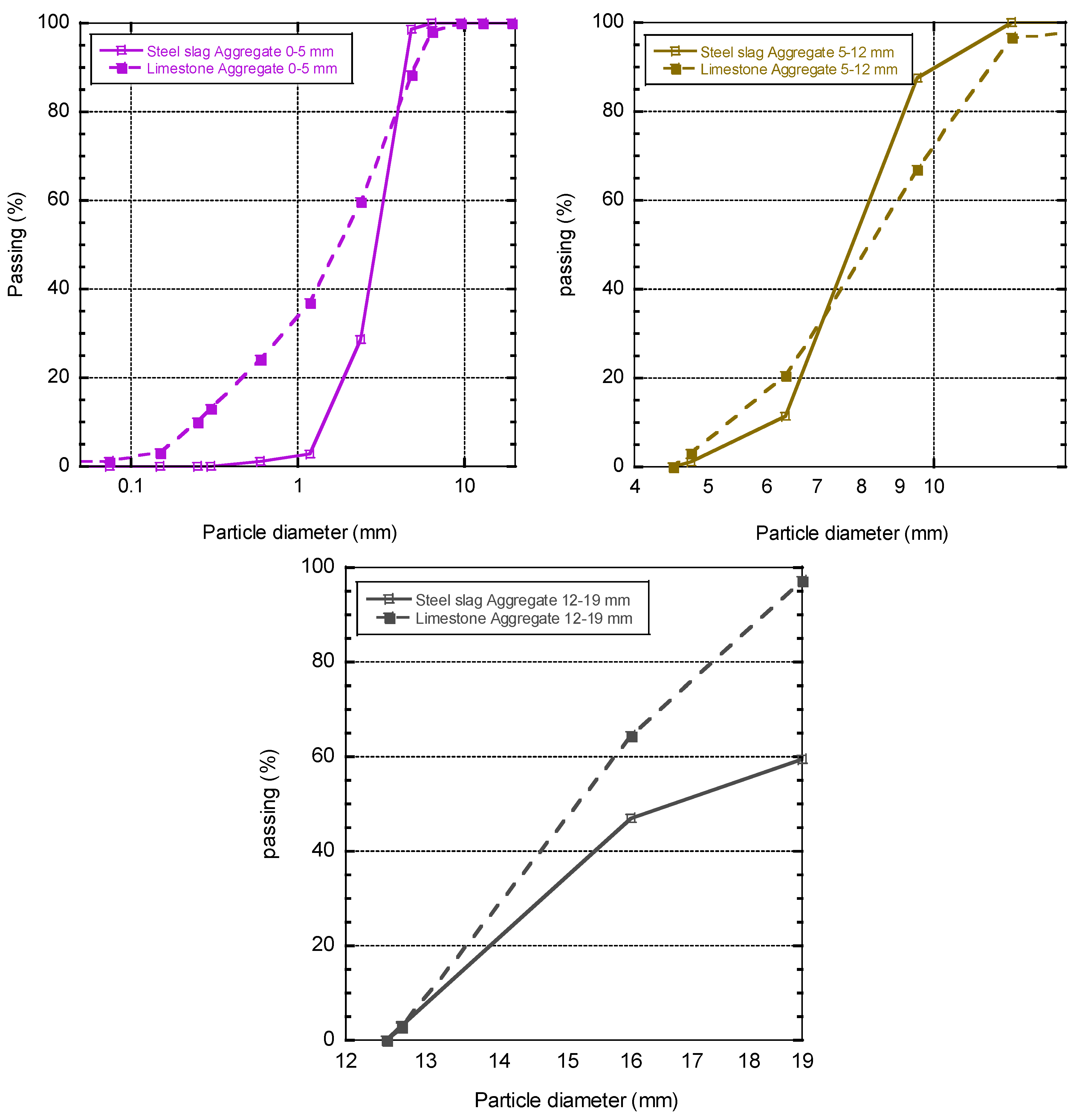
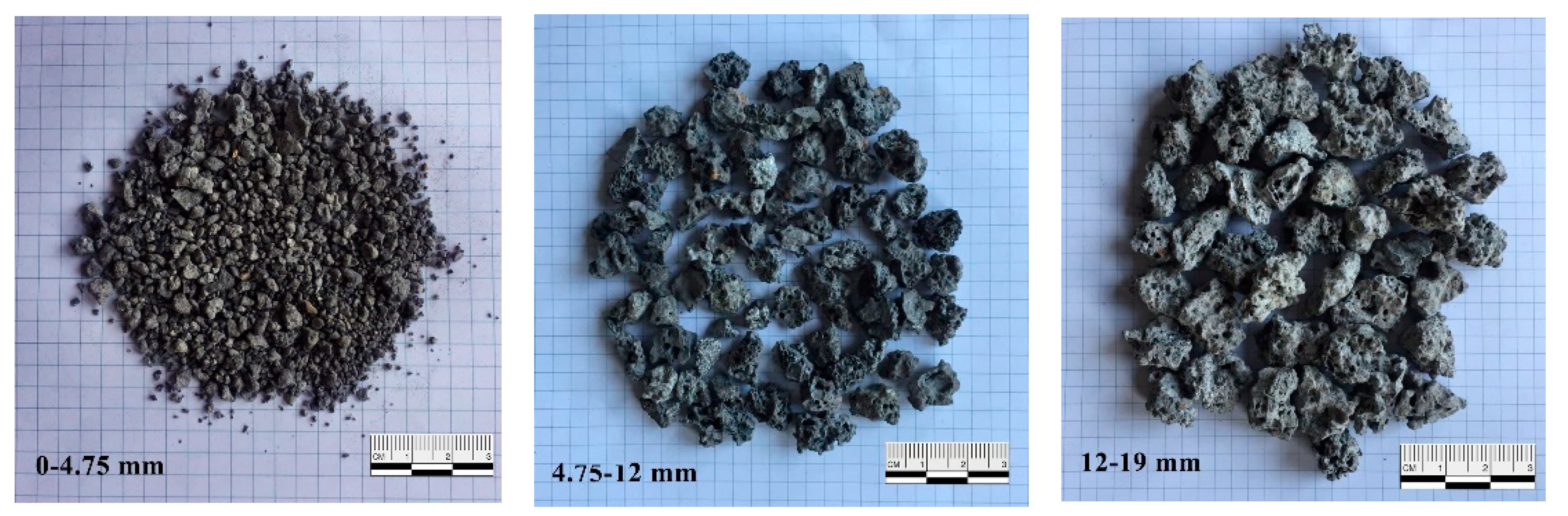
In this research, natural limestone aggregates according to standard ASTM C136M-19 Test Method for Sieve Analysis of Fine and Coarse Aggregates [28] have been used. Physical properties of consumable aggregates are density according to standard ASTM C127-15 Test Method for Relative Density (Specific Gravity) and Absorption of Coarse Aggregate [29] and water absorption according to standard ASTM C70-20 Test Method for Surface Moisture in Fine Aggregate [30]. Table 2 and Table 4 and also Figure 1 show the results of natural aggregate and EAFS grading analysis. The maximum size of aggregate used is 19 mm in accordance with the requirements of Standard ASTM C33M-18 Specification for Concrete Aggregates [31]. The porosity of natural aggregates is also reviewed by Standard ASTM C29 Test Method for Bulk Density (“Unit Weight”) and Voids in Aggregate [32]. The natural aggregates were acquired from a local source. The sand used for this research was obtained from Isfahan (Iran), a local source, and Industrial waste slag was obtained from a local steel plant called Isfahan Steel Co. According to Standard BS 1047 Specification for air-cooled blast furnace slag aggregate for use in construction [33], all EAFS in the open environment (Bank slag) and slowly cooled to find crystalline shape and are suitable for use as aggregate. Figure 2 shows aggregate sizes used.
2.1.3. Addition
The micro-silica used in this research is a product of Arvin Padir Co; it is micro-silica grade 920 ASTM with standard ASTM E1621-13 Guide for Elemental Analysis by Wavelength Dispersive X-ray Fluorescence Spectrometry [34], Standard ASTM C1240-20 Guide for Elemental Analysis by Wavelength Dispersive X-ray Fluorescence Spectrometry [35], and the optimal consumption recommended by the manufacturer can be changed from 2% to 10% by weight of cement depending on the increase in strength or increase in useful life and durability of the desired concrete. Table 2 and Table 5 show the physical properties and the technical specifications of the micro-silica used.
2.2. Experimental Details
2.2.1. Control Concrete Production
To get started, first, three initial designs were made with different percentages of cement and lubricant. In the control concrete mixing plan, no replacement of natural aggregate with EAFS aggregate and micro-silica is used, and it is considered only to find a suitable design to achieve a base strength of 40 MPa. In all designs, the ratio of water to cement consumption (w/c) was fixed and equal to 0.45. Before using the aggregates in making concrete, we putted them in the open air for three days and, of course, under the canopy in order to prevent them from getting wet, and then, we weighted them for each series of construction and put them in a bag. Since the ratio of water to cement is considered in the mixing plan, the conditions of Saturated-surface-dry (SSD) materials are considered, but our consumables, which are collected through the above, do not meet the conditions of SSD materials. Therefore, calculate the water absorption of aggregates and their moisture and add the amount of moisture absorption difference to the amount of water obtained from the ratio of water to cement, so that the material conditions approach the SSD state. First, before mixing the ingredients in the mixer, by adding water to the mixer, the mixer was allowed to rotate with the water for a few seconds, in addition to reducing the friction of the ingredients with the mixer body, reducing the adhesion of materials to the mixer surface and preventing its separation from the material. The method of mixing was that first the aggregates were mixed in the mixer for two minutes and dry, then cement was added, and the materials were mixed for one minute; then, water following specifications was added to the design and mixed for one minute.
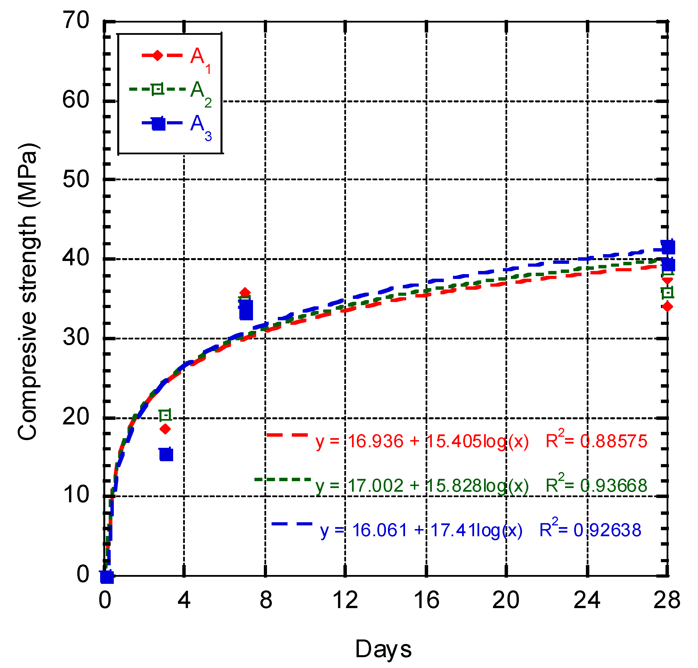
In order to achieve the resistance of the target 40 MPa, three samples were made with different percentage of materials that were briefly called (A1, A2, A3). The results of 3-, 7- and 28-days strength of base concretes samples are presented in continue. According to the resistance of 40.91 MPa. The third design (A3) was selected as the control design and from this part onwards, the samples marked (A3) indicate the control concrete. Table 6 shows physical properties and compressive strength of the basic concrete.
2.2.2. Mix Design
After determining the mixing plan of control concrete (A3) in the first stage, then, in the second stage, the natural aggregate of control concrete was replaced with slag aggregate in 25, 50, 75, 100% and in two separate categories of coarse and fine grains. Only different percentages of coarse grains were replaced, and in the next stage, only fine grains were replaced with different percentages, the optimal of this stage. In the third stage, micro-silica was added to the concrete with 6, 8, 10% wt. of cement, the optimal of this stage. The proposed mixing schemes are based on the weighting method and based on the recommendations provided in Standard ACI 211.1-91 Practice for Selecting Proportions for Normal, Heavyweight, and Mass Concrete [36]. Samples were prepared and mixed according to Standard ASTM C192M-19 Practice for Making and Curing Concrete Test Specimens in the Laboratory [37]; standard and their processing were performed based on the recommendations provided in Standard ASTM C51-20 Terminology Relating to Lime and Limestone [38]. After moulding, the samples were compacted by a vibrating table and covered. The moulds were opened after 24 h, and the specific gravity of the samples was measured. Then, the samples were transferred to a pool of water and treated for 27 days submerged in water at a temperature of about 20 °C ± 2 °C. The mix proportions used in the present research appear in the Table 7.
2.2.3. Testing Program
Four tests were considered for this study. Compressive strength test, flexural strength test, tensile strength test and elastic modulus test. To test the compressive strength, 20 cubic specimens with dimensions 150 × 150 × 150 mm were made for the 7-, 28-, 42-, 90-day test, this test was performed according to standard EN12390- 3 Compressive strength of test specimens [39]. To test the flexural strength, 6 cubic specimens 100 × 100 × 350 mm were made for 7- and 28-day testing, and this test was performed according to standard ASTM C469M-14e1 Test Method for Flexural Strength of Concrete [40]. Compressive strength test according to standard EN12390- 3 Compressive strength of test specimens [39] has been performed on cubic specimens with dimensions of 150 mm. First, samples of the cube sample were made to investigate the difference in compressive strengths in the way the prismatic is placed in the compression device, so that if the results are not noticeable, the coping operation is omitted for ease of work. With a difference of 1% in the compressive strength results, the method of placing the specimens as two opposite surfaces that were adjacent to the formwork during concreting, in contact with the upper and lower stirrups of the machine, was selected. According to Standard UNE-EN 12390-5:2020 Testing hardened concrete—Part 5: Flexural strength of test specimens [41], beam dimensions of 350 × 100 × 100 mm were selected.
The distance between the two upper supports was 100 mm, and the distance between the two lower supports was 300 mm. Vertical load was applied at a loading rate of 0.6 mm/min. According to ASTM C78 Test Method for Flexural Strength of Concrete [42], concrete formwork beams are cracked using a four-point loading device using steel sheet, which helps keep the concrete specimen in the initial loading cycle. The reason for using this steel sheet was to help control the displacement rate when the beam cracked. After the beam is cracked in a certain way, the steel sheet is removed, and the cracked beam is reloaded to obtain the information of the displacement load curve. Load values are averaged at the displacement values specified in the reload curve and are used to calculate the average residual strength of the beam.
Figure 3 shows how to set up the device and the sample for the average residual strength tests. To obtain the flexural strength of concrete samples, after 28 days of processing and being placed in a water bath, four-point bending loads are placed.
3. Results and Discussion
3.1. Fresh Properties
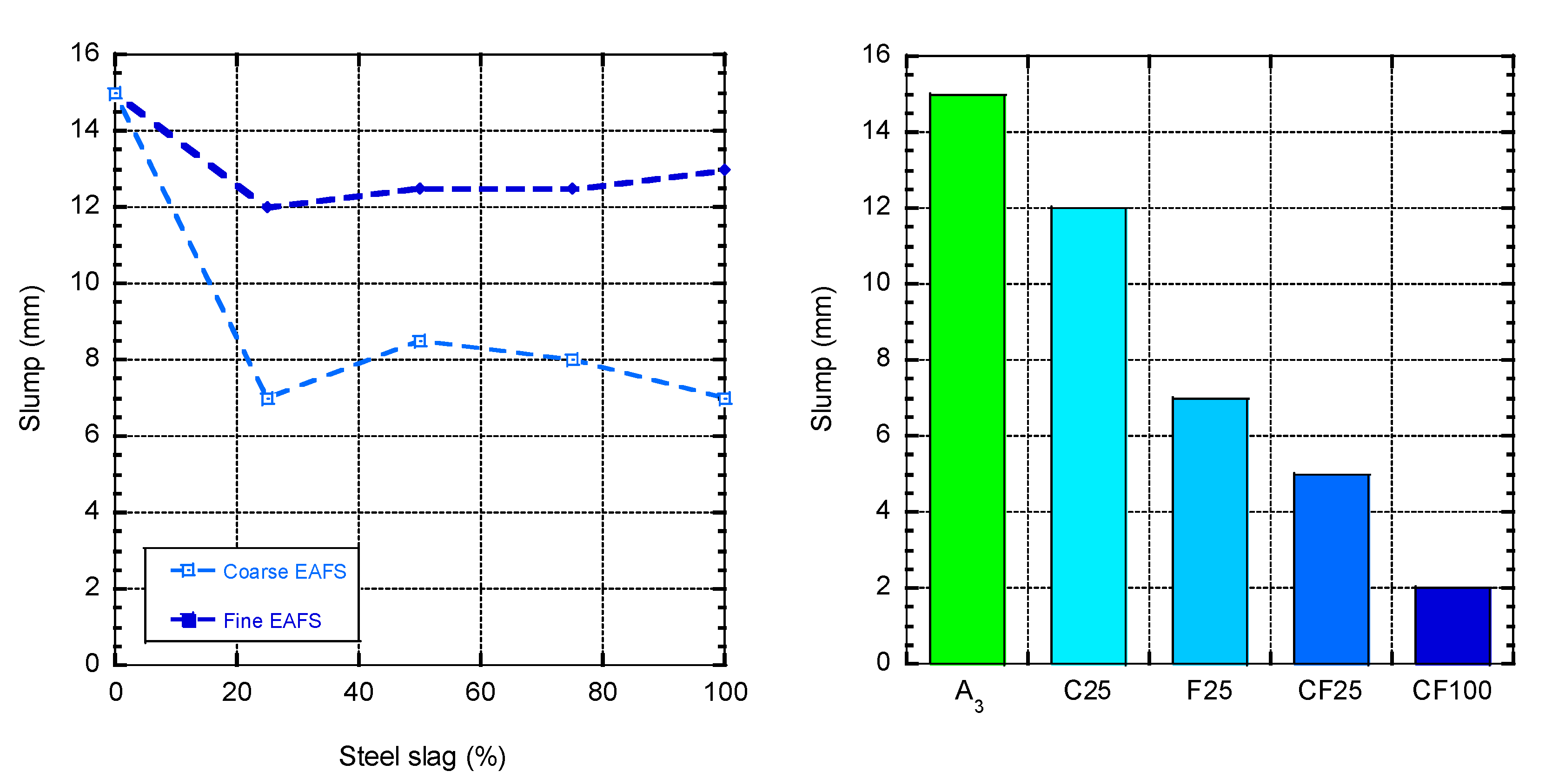
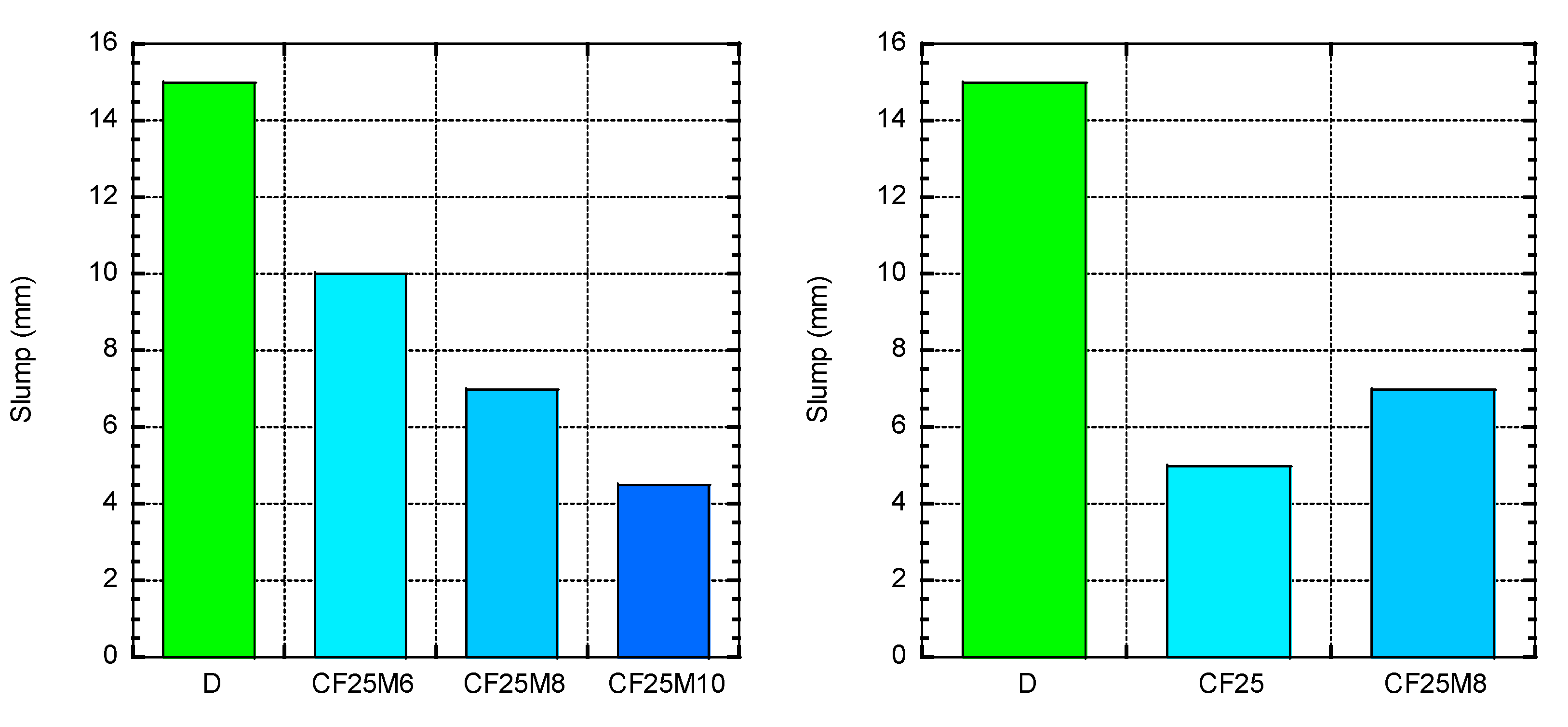
Figure 4 lists the slump test results measured with the corresponding concrete consistency and shows the results of inspecting samples C25 and F25. In all of the above cases, the results come from only one trial for each mixture. The results show that the mixture with natural aggregates has a soft or plastic consistency, while other mixtures made of EAFS have a dry consistency in all cases. The use of EAFS as coarse and fine aggregates will result in lower slump, thereby reducing the workability of concrete. Compared with siliceous aggregates, this is due to the rough shape and higher water absorption of EAFS [43] In addition, as other authors have pointed out, due to the greater specific gravity of EAFS relative to siliceous aggregates, the fresh density of the mixture shows an important increase in concrete made with EAFS. Figure 5 concrete contains different percentage of micro-silica and also optimized each of the previous steps. Due to the fact that with the increase of EAFS aggregates concrete slump decreases, the amount of superplasticizer was increased to 0.8% to keep the concrete slump acceptable, and according to the factory instructions, SP consumption should not exceed the maximum allowed 1.2%. It can be concluded that under the same conditions, the water absorption rate of EAFS fine aggregate is greater than that of EAFS coarse aggregate. This may be due to the low density and coarseness of EAFS fine particles [44]. Compared with aggregate, this directly affects the workability, and the slump has concrete. In the CF25 sample adding EFAS coarse aggregate to the mixture containing fine aggregate, it can be seen that adding only 25% of the EAFS coarse aggregate can greatly improve the workability and improve the slump. This is due to the coarse aggregates’ higher porosity, indicating that if EAFS coarse aggregates are used, the amount of water used in the mixing plan should be reconsidered. The fresh density of the concrete mixture is also shown in Figure 6.
3.2. Hardened Properties
In the present study, the mechanical properties of concrete made in 37 mixing designs with different percentages of EAFS and replacement have been investigated. Compressive strength tests were performed on these designs at the ages of 7, 28, 42 and 90 days. The results of sample C25 and sample F25 show that the use of separate EAFS fine or coarse aggregates has no effect on the density of concrete, and this degree of difference is due to the contrasting weights of these aggregates used in the mixing design. It is clear that the density of concrete increases with increasing replacement of natural with EAFS aggregate [45]. Figure 7 concrete contains different percentage of micro-silica and also optimized each of the previous steps.
3.2.1. Compressive Strength
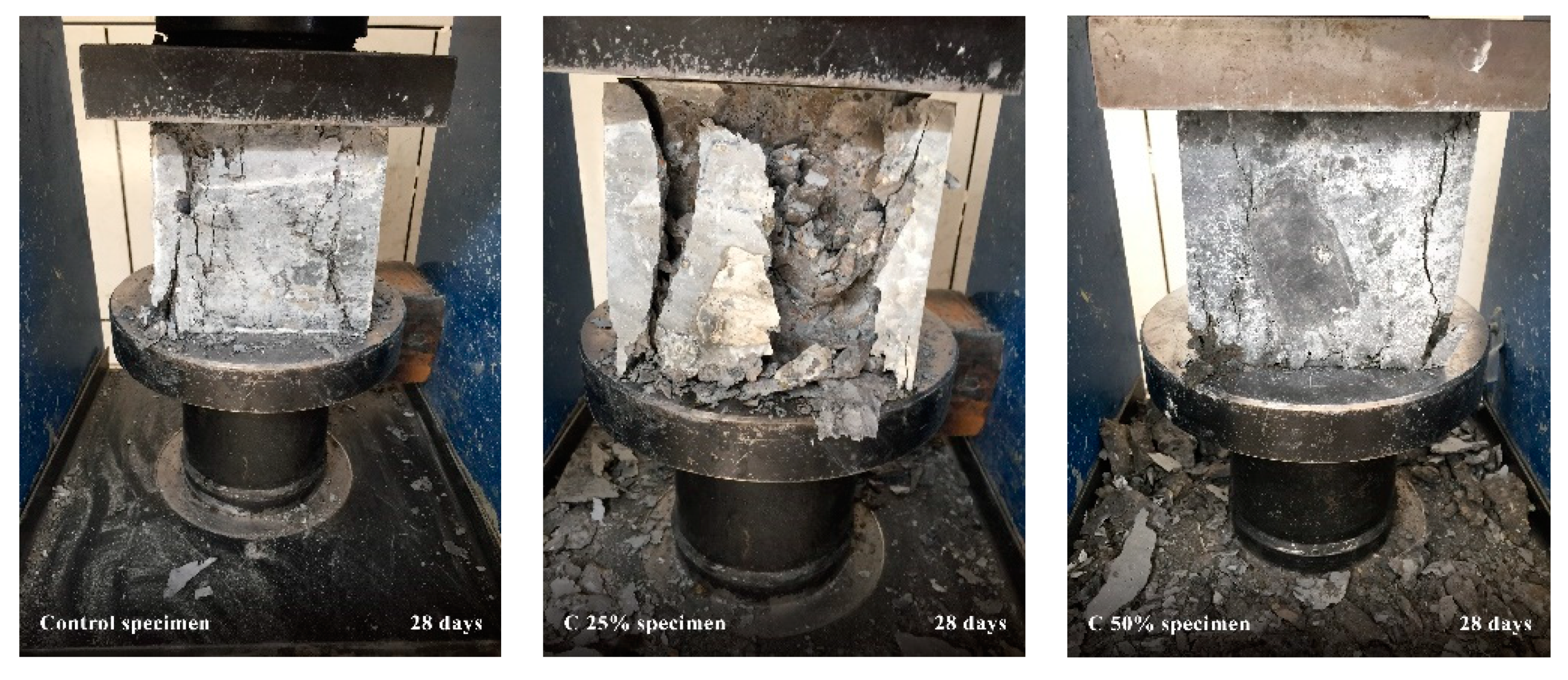
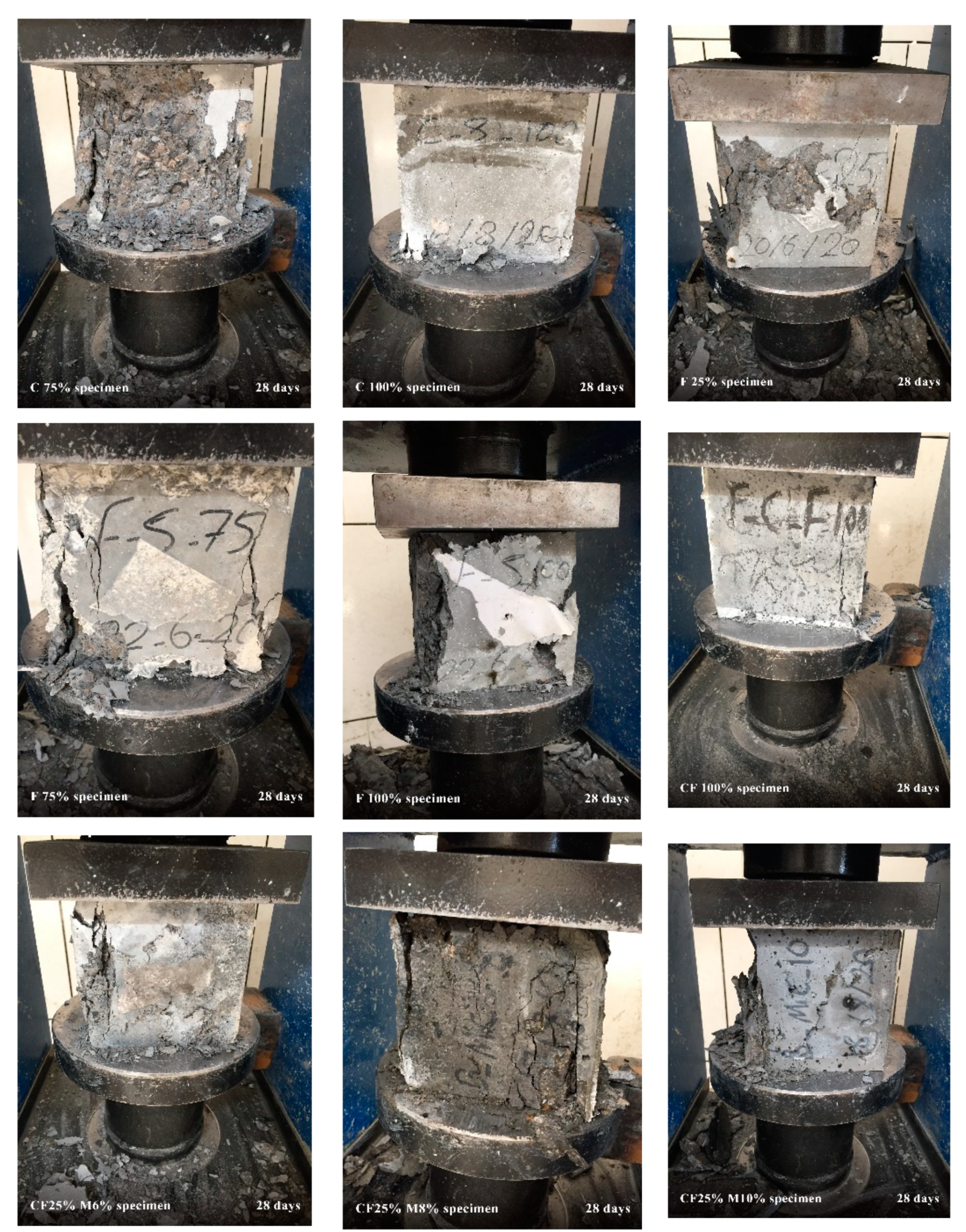
The result is obtained by dividing this force by the cross section of the sample. Compressive strength increased with age of the samples. In the mixing schemes of this study, the ratio of water to cement is the same. Therefore, the effect of this factor is the same in all concretes, and the variable factor in this study is the different percentage of EAFS as aggregates and cement have been consumed. Fracture speed in samples with 100% coarse EAFS aggregates was faster than in samples with 100% fine EAFS aggregates. Due to the fact that all the factors in the mixing design and processing steps are the same in all samples, as well as using the same speed and pressure to crack the samples, this can only be due to the type and size of aggregates used. Figure 8 shows an example of breaking different designs under constant pressure and velocity. Figure 9 shows consumable cement, due to high softness, has a significant effect on concrete compressive strength, so that compressive strength in 10 days has gained more than 50% compressive strength in 28 days.
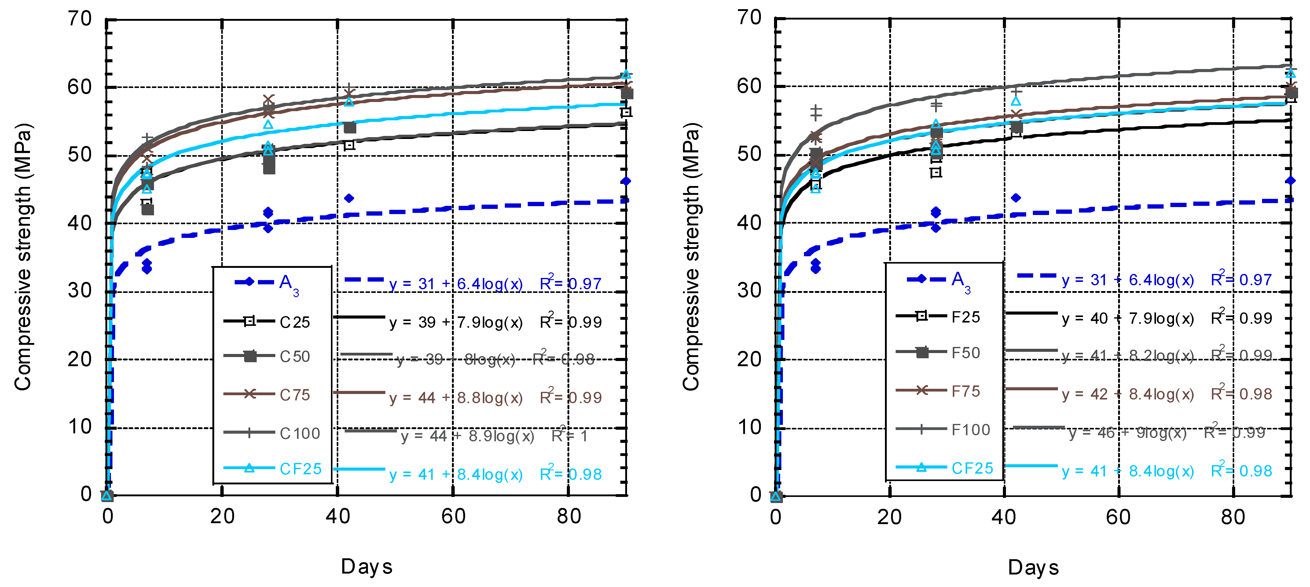
In all designs, with increasing replacement of EAFS aggregates in the samples, we see an increase in compressive strength to control concrete. By replacing EAFS as aggregates (coarse and fine) from zero to 100%, we see an increase in compressive strength. As can be seen in Figure 10 samples with coarse-aggregates, EAFS show higher compressive strength than samples with EAFS fine-aggregates replacement, but this amount is not very high; as expected, the highest amount of resistance is related to the replacement of 100% of natural aggregate with EAFS. It is observed that the replacement strengths of 75% and 100% of coarse aggregates have the same and close behaviour, which is also observed in 50% and 75% of fine grains. By replacing the top of the consumed aggregates with natural aggregates, the strength of the samples increases sharply, but this increase in resistance is also accompanied by a large increase in the density of the samples. After 90 days, it is observed that the strength of 25, 50 and 75% EAFS fine-aggregates samples is equal to the strength of samples with 25 and 50% EAFS coarse-aggregates. To control the specific gravity of the samples, which do not become too heavy during the next steps, 25% coarse and fine aggregates replacement with 90-day resistance with 100% fine-aggregates replacement strength and 50 and 75% coarse-aggregates replacement are close and imperceptible.
Considering the sustainability of EAFS and its lack of reactivity with other materials, the behaviour and reaction between cement and EAFS is only a physical reaction, and no chemical reaction occurs.
Figure 10 shows that in the same sizes of aggregates, EAFS have better performance than natural aggregates in compressive strength, so that by replacing 50% aggregates, compressive strength of about 10 MPa increases compared to control concrete (A3). The particle size used by micro-silica used in this study has had a great impact on the process of acquiring concrete strength. This led the activity between cement and micro-silica, and concrete reached the ultimate resistance earlier than normal, also increasing compressive strength in concrete, with an increase of 10 MPa to the substance, the final resistance being about 71 MPa.
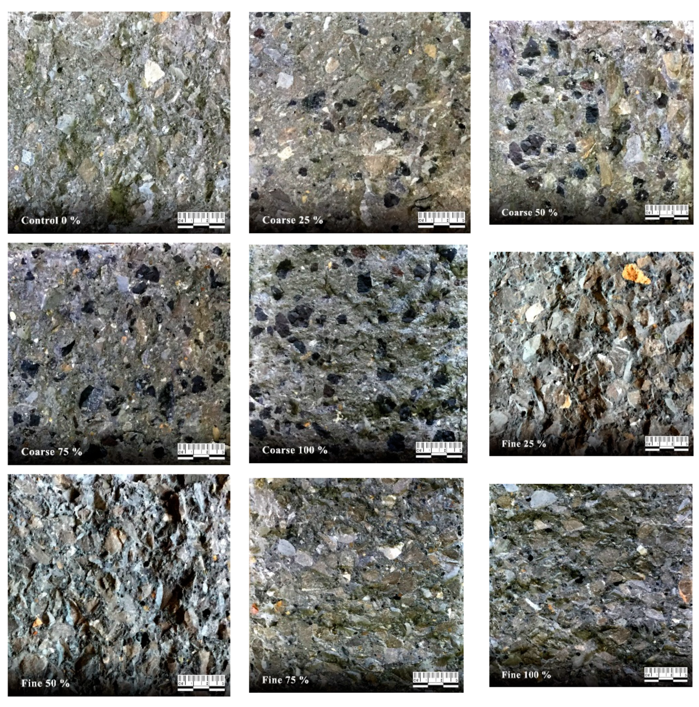
EAFS aggregates have a higher density than natural aggregates, but as shown in Figure 11, EAFS aggregates have a good dispersion on the concrete surface, and this may indicate that despite the heavier weight of this aggregate, it can be used without worrying about settling in the concrete due to the transport time or vibration of the concrete.
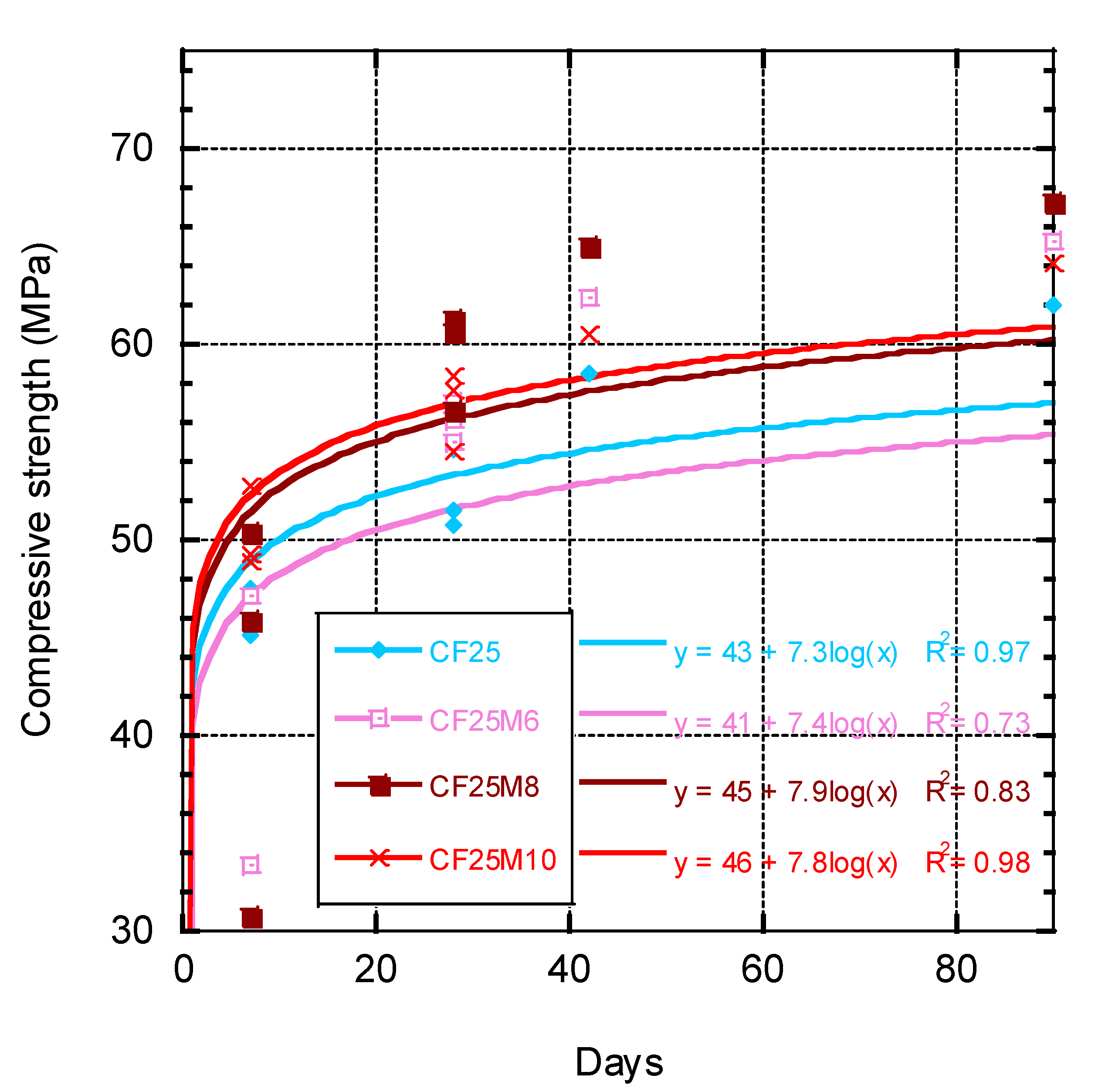
As shown in Figure 12 below, by increasing the percentage of micro-silica additive to 8% wt. of cement, we are faced with an increase in strength. In this descending process, compressive strength decreases, due to increased chemical reaction between micro-silica and cement consumption. The noteworthy point in the diagram is that all samples display significant differences to the strength of the control sample except CF25M6, also at the age of 7 days, where there is a slight difference. This shows that at this age, micro silica only plays the role of filler. Moreover, samples containing 8% micro-silica have a higher strength after 90 days than other samples. In other samples, with the increase in micro-silica, no further increase in compressive strength is observed. CF25M8 and CF25M10 have increased strength at 90 days of age compared to the control sample. However, in the rest of the samples, the increase in strength was less. With the addition of micro-silica, a large increase in strength is observed in the samples. Another noteworthy point is that the compressive strength of CF25M8 and CF25M10 after 7 days is 3 and 6% higher than the control strength, respectively. This point also emphasizes that until the age of 7 days, micro-silica has only a fine filler role and performs most of its activities between the ages of 7 and 90 days. The best-case scenario is to use 8% micro-silica. It can also be concluded from Figure 12 that micro-silica in all percentages and in all proportions does not increase the strength in an acceptable way. The reason for this is that the micro-silica at this age of 7 days has still not fully developed its function.
3.2.2. Flexural Strength
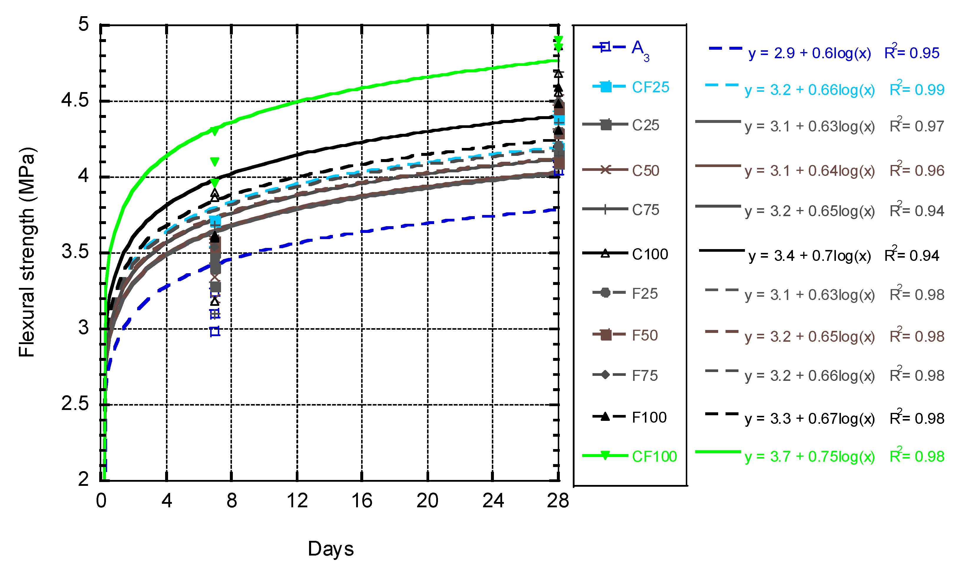
Figure 13 shows the flexural strength changes with respect to the replacement proportion of EAFS aggregates. The results indicate that the replacement of EAFS fine aggregates, although it increases the flexural strength, does not have a significant effect. However, with replacement of more than 75% of EAFS coarse aggregates with natural coarse aggregate, a sudden increase in the flexural strength of the samples is obtained. Although in the seven-day strength, the results of flexural strength of all samples are close to each other, it can be clearly seen that, with the addition of 75% of EAFS coarse aggregates, after ten days, the process of obtaining flexural strength increases with a high slope. Considering that the mixing design is the same in all samples and the process of obtaining flexural strength in samples with EAFS fine-aggregates is continuous and slow, it can be concluded that this type of performance is not related to the type of cement used or other items, and it all has to do with EAFS coarse aggregates. This may be due to the fact that EAFS coarse aggregates will have more contacts with each other than EAFS fine aggregates due to greater porosity and rougher surfaces, and as a result, they will increase strength.
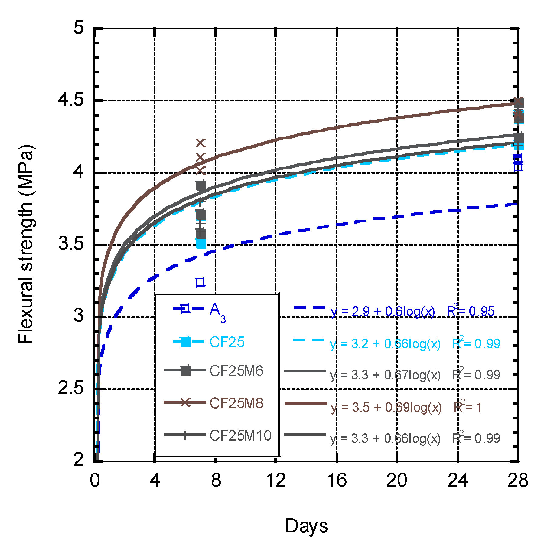
The results in Figure 14 show that the addition of micro-silica into control concrete does not affect the flexural strength of the sample, and the strength of these samples is equal to control concrete. Therefore, adding 6% of micro-silica to the sample has no special effect on the flexural strength of the sample. This may be due to the fact that micro-silica grains are much smaller than cement. In this case, due to high porosity in EAFS aggregates, micro-silica is forced to fill the aggregate cavities. The greatest effect is related to adding 8% of micro-silica to the sample, when the porosity of the aggregates is saturated with water and filled with micro-silica, and micro-silica plays its role as a pozzolanic adhesive. After increasing the micro-silica to 10% wt. of cement, the flexural strength decreases sharply, which means that by keeping the water to cement ratio and the amount of concrete SP constant, there will not be enough water for hydration.
3.3. SEM Analyze
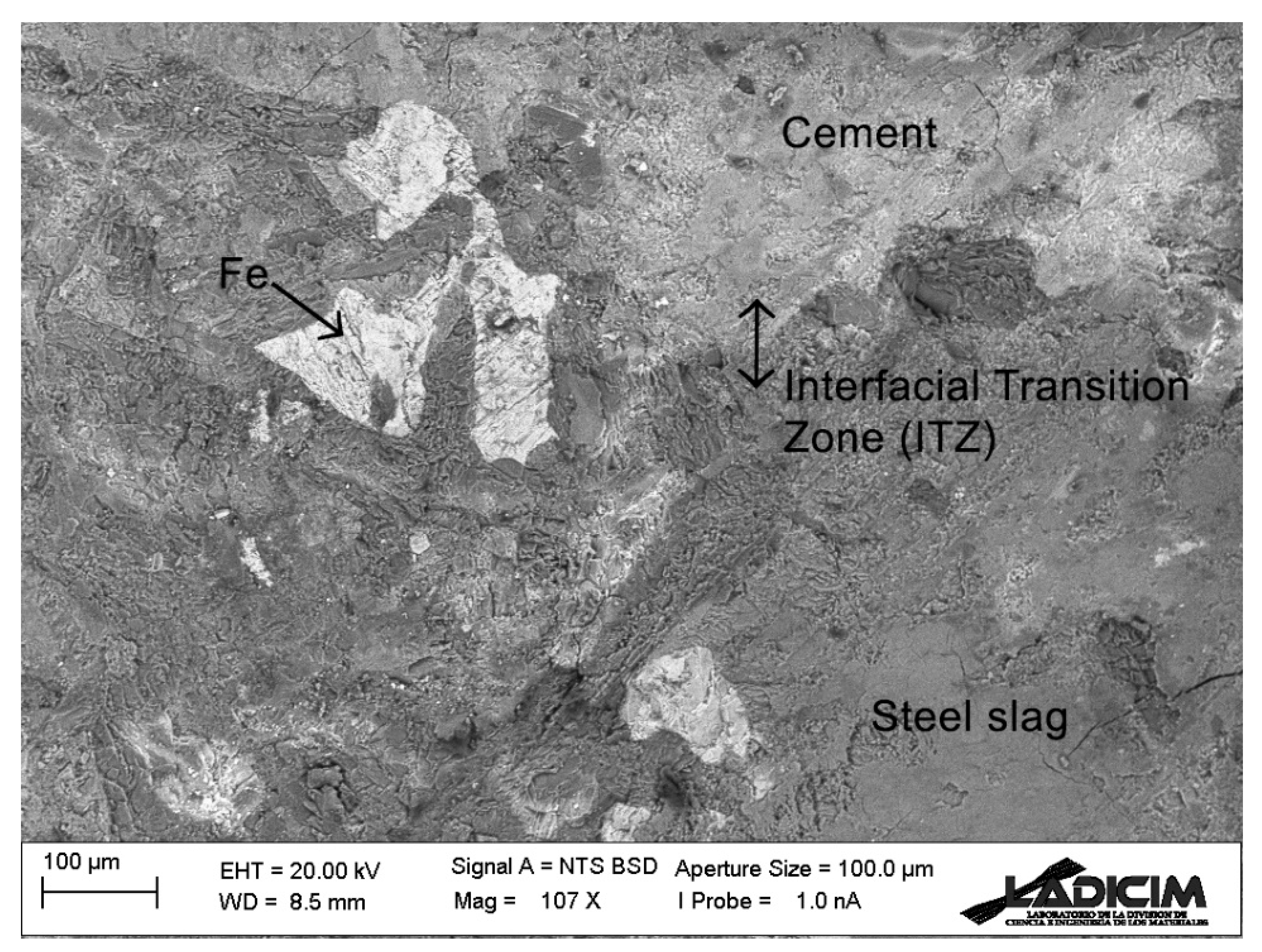
Scanning Electron Microscope (SEM) analysis shows that EAFS aggregate has a good overlap with cement. As shown in Figure 15, there is a good connection at the boundary between EAFS aggregate and cement, and there is no empty space between cement and EAFS aggregate and complete adhesion has occurred, which plays an important role in gaining strength in concrete. It can also be seen that the amount of iron in EAFS aggregate is less than 0.1% wt. of aggregate. It should also be noted that the sample examined is a sample with a polished surface.
4. Conclusions
This study investigated the compressive and flexural behaviour of EAFS with micro-silica additive in concrete. From the above discussion, the following conclusions can be drawn:
- Examining the results of samples C25 and F25, it can be concluded that under the same conditions, water absorption of EAFS fine aggregates is greater than that of EAFS coarse aggregates, which may be due to the low density of EAFS fine-grained compared to coarse aggregates, which has a direct effect on workability and the slump has concrete.
- In CF25 sample, with the addition of EFAS coarse aggregates to the mixture containing fine aggregates, it can be seen that adding only 25% of EAFS coarse aggregates can greatly help workability and improve slump, which is due to more porosity in coarse aggregates and shows that if EAFS coarse aggregates is used, the amount of water used in the mixing plan should be reconsidered.
- By adding micro-silica, 6% wt. of cement in a mixing design in the CF25M6 sample, workability can be largely increased and slump concrete, which is very important in the production of high resistance concrete.
- Comparing the CF25M8 design with the D design, it can be seen that the density of these two designs is close to each other, and this shows that by optimizing the percentage of use of EAFS aggregates to the compressive strength obtained, it can be used in the production of structural concrete. It is important to use this.
- The results show that the replacement of more than 75 coarse and 50 fine aggregates EAFS, except for increasing the density, does not have a significant effect on gaining more compressive strength.
- Addition of micro-silica up to 8% significantly increases the strength in concrete with EAFS aggregates, but by increasing its amount, the process of gaining strength decreases to the point that by adding 10% micro-silica, this trend is reversed, and the compressive strength decreases to CF25 concrete compressive strength.
- In terms of compressive strength, there is not much difference between the samples containing 6% CF25M6 micro-silica and 8% CF25M8 micro-silica, but the workability of the first sample is much higher than that of the second sample.
- Increasing the percentage of EAFS fine aggregates does not have a significant effect on the acquisition of flexural strength, but increasing more than 50% of EAFS coarse aggregates, the flexural strength increases at once.
- Consumption of micro-silica up to 6% has no effect on flexural strength, so that the flexural strength of CF25 and CF25m6 samples is almost the same, which means that EAFS fine aggregates in the process of obtaining strength have a good density and continuity.
Author Contributions
Conceptualization, A.A. and C.T.; methodology, A.A. and C.T., validation, K.B. and A.A.; formal analysis, A.A., C.T. and K.B.; investigation, A.A.; data curation, A.A.; writing—original draft preparation, A.A. and C.T.; writing—review and editing C.T., K.B. and A.A.; visualization, A.A.; supervision, C.T. and K.B.; project administration, C.T. and K.B. All authors have read and agreed to the published version of the manuscript.
Funding
Not applicable.
Institutional Review Board Statement
Not applicable.
Informed Consent Statement
Not applicable.
Data Availability Statement
The data presented in this study are openly available.
Acknowledgments
The authors of this research would like to thank Isfahan University of Technology (IUT) for help with performing the required tests, Bonyad Beton for providing a laboratory environment for making concrete samples and Esfahan Steel Company for the EAFS aggregates.
Conflicts of Interest
The authors declare no conflict of interest.
References
- Monosi, S.; Ruello, M.L.; Sani, D. Electric arc furnace slag as natural aggregate replacement in concrete production. Cem. Concr. Compos. 2016, 66, 66–72. [Google Scholar] [CrossRef]
- Brand, A.S.; Roesler, J.R. Steel furnace slag aggregate expansion and hardened concrete properties. Cem. Concr. Compos. 2015, 60, 1–9. [Google Scholar] [CrossRef]
- Manso, J.M.; Polanco, J.A.; Losañez, M.; González, J.J. Durability of concrete made with EAF slag as aggregate. Cem. Concr. Compos. 2006, 28, 528–534. [Google Scholar] [CrossRef]
- Ortega-López, V.; Fuente-Alonso, J.A.; Santamaría, A.; San-José, J.T.; Aragón, Á. Durability studies on fiber-reinforced EAF slag concrete for pavements. Constr. Build. Mater. 2018, 163, 471–481. [Google Scholar] [CrossRef]
- Yearbook, S.S. World Steel; World Steel Association, Production: Brussels, Belgium, 2014. [Google Scholar]
- Yüksel, İ. A review of steel slag usage in construction industry for sustainable development. Environ. Dev. Sustain. 2017, 19, 369–384. [Google Scholar] [CrossRef]
- Maghool, F.; Arulrajah, A.; Du, Y.-J.; Horpibulsuk, S.; Chinkulkijniwat, A. Environmental impacts of utilizing waste steel slag aggregates as recycled road construction materials. Clean Technol. Environ. Policy 2016. [Google Scholar] [CrossRef]
- Koros, P.J. Dusts, Scale, Slags, Sludges. Not Wastes, but Sources of Profits. Metall. Mater. Trans. B Process Metall. Mater. Process. Sci. 2003, 34, 769–779. [Google Scholar] [CrossRef]
- Arribas, I.; Santamaría, A.; Ruiz, E.; Ortega-López, V.; Manso, J.M. Electric arc furnace slag and its use in hydraulic concrete. Constr. Build. Mater. 2015, 90, 68–79. [Google Scholar] [CrossRef]
- Pellegrino, C.; Faleschini, F. Sustainability Improvements in the Concrete Industry. Sustain. Improv. Concr. Ind. 2016, 141–175. [Google Scholar] [CrossRef]
- Thomas, C.; Setién, J.; Polanco, J.A.; Alaejos, P.; Sánchez De Juan, M. Durability of recycled aggregate concrete. Constr. Build. Mater. 2013, 40, 1054–1065. [Google Scholar] [CrossRef]
- Sosa, I.; Thomas, C.; Polanco, J.A.; Setién, J.; Tamayo, P. High Performance Self-Compacting Concrete with Electric Arc Furnace Slag Aggregate and Cupola Slag Powder. Appl. Sci. 2020, 10, 773. [Google Scholar] [CrossRef] [Green Version]
- Tamayo, P.; Pacheco, J.; Thomas, C.; de Brito, J.; Rico, J. Mechanical and Durability Properties of Concrete with Coarse Recycled Aggregate Produced with Electric Arc Furnace Slag Concrete. Appl. Sci. 2019, 10, 216. [Google Scholar] [CrossRef] [Green Version]
- Wang, G.; Wang, Y.; Gao, Z. Use of steel slag as a granular material: Volume expansion prediction and usability criteria. J. Hazard. Mater. 2010, 184, 555–560. [Google Scholar] [CrossRef] [PubMed]
- Pasetto, M.; Baldo, N. Mix design and performance analysis of asphalt concretes with electric arc furnace slag. Constr. Build. Mater. 2011, 25, 3458–3468. [Google Scholar] [CrossRef]
- Pellegrino, C.; Cavagnis, P.; Faleschini, F.; Brunelli, K. Properties of concretes with black/oxidizing electric arc furnace slag aggregate. Cem. Concr. Compos. 2013, 37, 232–240. [Google Scholar] [CrossRef]
- Shelburne, W.M.; Degroot, D.J. The use of waste & recycled materials in highway construction. Civ. Eng. Pract. 1998, 13, 5–16. [Google Scholar]
- Fiol, F.; Thomas, C.; Muñoz, C.; Ortega-López, V.; Manso, J.M. The influence of recycled aggregates from precast elements on the mechanical properties of structural self-compacting concrete. Constr. Build. Mater. 2018, 182, 309–323. [Google Scholar] [CrossRef]
- Roy, S.; Miura, T.; Nakamura, H.; Yamamoto, Y. High temperature influence on concrete produced by spherical shaped EAF slag fine aggregate–Physical and mechanical properties. Constr. Build. Mater. 2020, 231, 117153. [Google Scholar] [CrossRef]
- Drzymała, T.; Jackiewicz-rek, W.; Gałaj, J.; Šukys, R. Assessment of Mechanical Properties of High Strength Concrete (Hsc) After Exposure To High Temperature. J. Civ. Eng. Manag. 2018, 24, 138–144. [Google Scholar] [CrossRef] [Green Version]
- Sofilić, T.; Barišić, D.; Rastovčan Mioč, A.; Sofilić, U. Radionuclides in steel slag intended for road construction. J. Radioanal. Nucl. Chem. 2010, 284, 73–77. [Google Scholar] [CrossRef]
- Drzymała, T.; Łukaszek-Chmielewska, A.; Lewicka, S.; Stec, J.; Piotrowska, B.; Isajenko, K.; Lipiński, P. Assessment of the natural radioactivity of Polish and foreign granites used for road and lapidary constructions in Poland. Materials 2020, 13, 2824. [Google Scholar] [CrossRef] [PubMed]
- Manso, J.M.; Gonzalez, J.J.; Polanco, J.A. Electric Arc Furnace Slag in Concrete. J. Mater. Civ. Eng. 2004, 16, 639–645. [Google Scholar] [CrossRef]
- Papayianni, I.; Anastasiou, E. Production of high-strength concrete using high volume of industrial by-products. Constr. Build. Mater. 2010, 24, 1412–1417. [Google Scholar] [CrossRef]
- Ardestan Cement. 2021. Available online: https://www.ardestancement.com/home/en (accessed on 25 May 2021).
- Durocem. 2021. Available online: http://www.durocem.ir/index.php/en (accessed on 25 May 2021).
- ASTM C494M-19. ASTM C494/C494M-19, Standard Specification for Chemical Admixtures for Concrete; ASTM International: West Conshohocken, PA, USA, 2019. [Google Scholar] [CrossRef]
- ASTM C136M-19. ASTM C136/C136M-19, Standard Test Method for Sieve Analysis of Fine and Coarse Aggregates; ASTM International: West Conshohocken, PA, USA, 2019. [Google Scholar] [CrossRef]
- ASTM C127-15. ASTM C127-15, Standard Test Method for Relative Density (Specific Gravity) and Absorption of Coarse Aggregate; ASTM International: West Conshohocken, PA, USA, 2015. [Google Scholar] [CrossRef]
- ASTM C70-20. ASTM C70-20, Standard Test Method for Surface Moisture in Fine Aggregate; ASTM International: West Conshohocken, PA, USA, 2020. [Google Scholar] [CrossRef]
- ASTM C33M-18. ASTM C33/C33M-18, Standard Specification for Concrete Aggregates; ASTM International: West Conshohocken, PA, USA, 2018. [Google Scholar] [CrossRef]
- ASTM C29. ASTM C29/C29M-17a, Standard Test Method for Bulk Density (“Unit Weight”) and Voids in Aggregate; ASTM International: West Conshohocken, PA, USA, 2017. [Google Scholar] [CrossRef]
- British Standards Institution BS 1047. Specification for Air Cooled Blast Furnace Slag Aggregate for Use in Construction; British Standards Institution: London, UK, 1983. [Google Scholar]
- ASTM E1621-13. ASTM E1621-13, Standard Guide for Elemental Analysis by Wavelength Dispersive X-ray Fluorescence Spectrometry; ASTM International: West Conshohocken, PA, USA, 2013. [Google Scholar] [CrossRef]
- ASTM C1240-20. ASTM C1240-20, Standard Specification for Silica Fume Used in Cementitious Mixtures; ASTM International: West Conshohocken, PA, USA, 2020. [Google Scholar] [CrossRef]
- ACI 211.1-91. Standard Practice for Selecting Proportions for Normal, Heavyweight and Mass Concrete, ACI 211.1-91; American Concrete Institute: Farmington Hills, MI, USA, 1991. [Google Scholar]
- ASTM C192M-19. ASTM C192/C192M-19, Standard Practice for Making and Curing Concrete Test Specimens in the Laboratory; ASTM International: West Conshohocken, PA, USA, 2019. [Google Scholar] [CrossRef]
- ASTM C51-20. ASTM C51-20, Standard Terminology Relating to Lime and Limestone (as Used by the Industry); ASTM International: West Conshohocken, PA, USA, 2020. [Google Scholar] [CrossRef]
- EN12390-3. Testing Hardened Concrete-Part 3: Compressive Strength of Test Specimens. 2009. Available online: https://standards.iteh.ai/catalog/standards/cen/d1d94876-958b-4941-ade0-780076fc330a/en-12390-3-2009 (accessed on 25 May 2021).
- ASTM C469M-14e1. ASTM C469/C469M-14e1, Standard Test Method for Static Modulus of Elasticity and Poisson’s Ratio of Concrete in Compression; ASTM International: West Conshohocken, PA, USA, 2014. [Google Scholar] [CrossRef]
- UNE-EN 12390-5:2020. Testing Hardened Concrete-Part 5: Flexural Strength of Test Specimens; European Standards: Pilsen, Czech Republic, 2020. [Google Scholar]
- ASTM C78. STM C78/C78M-21, Standard Test Method for Flexural Strength of Concrete (Using Simple Beam with Third-Point Loading); ASTM International: West Conshohocken, PA, USA, 2021. [Google Scholar] [CrossRef]
- Manso, J.M.; Hernández, D.; Losáñez, M.M.; González, J.J. Design and elaboration of concrete mixtures using steelmaking slags. Aci Mater. J. 2011, 108, 673–681. [Google Scholar] [CrossRef]
- Faleschini, F.; Brunelli, K.; Zanini, M.A.; Dabalà, M.; Pellegrino, C. Electric Arc Furnace Slag as Coarse Recycled Aggregate for Concrete Production. J. Sustain. Metall. 2016, 2, 44–50. [Google Scholar] [CrossRef]
- Abu-Eishah, S.I.; El-Dieb, A.S.; Bedir, M.S. Performance of concrete mixtures made with electric arc furnace (EAF) steel slag aggregate produced in the Arabian Gulf region. Constr. Build. Mater. 2012, 34, 249–256. [Google Scholar] [CrossRef]
Figure 1.
Grading chart of natural aggregate and EAFS aggregate (0–5 mm), (5–12 mm), (12–19 mm).

Figure 2.
EAFS aggregate sizes used.

Figure 3.
How to adjust the device and sample to test the flexural strength.

Figure 4.
Slump of concrete containing different percentages of EAFS (left) and slump of concrete containing 25% of slag (right).
Figure 4.
Slump of concrete containing different percentages of EAFS (left) and slump of concrete containing 25% of slag (right).

Figure 5.
Slump of concrete containing different percentages of micro-silica (left) and slump of concrete optimal each of the previous parts (right).
Figure 5.
Slump of concrete containing different percentages of micro-silica (left) and slump of concrete optimal each of the previous parts (right).

Figure 6.
Density of concrete containing different percentages of EAFS (left) and density of concrete containing 25% of slag (right).
Figure 6.
Density of concrete containing different percentages of EAFS (left) and density of concrete containing 25% of slag (right).

Figure 7.
Density of concrete containing different percentages of micro-silica (left) and optimal density of concrete for each of the previous parts (right).
Figure 7.
Density of concrete containing different percentages of micro-silica (left) and optimal density of concrete for each of the previous parts (right).

Figure 8.
Crack patterns of the different mixes after the compressive strength test.


Figure 9.
Compressive strength of basic concrete.

Figure 10.
Compressive strength of replaced EAFS coarse aggregates concrete (left) and EAFS fine aggregates concrete (right).
Figure 10.
Compressive strength of replaced EAFS coarse aggregates concrete (left) and EAFS fine aggregates concrete (right).

Figure 11.
Detail of specimens with different percentages of coarse and fine EAFS aggregates.

Figure 12.
Compressive strength of concrete with different percentages of micro-silica.

Figure 13.
Flexural strength of concrete containing different percentages of EAFS aggregate.

Figure 14.
Flexural strength of concrete (D) with different percentages of micro-silica.

Figure 15.
Encounter of cement and EAFS aggregate in the interfacial transition zone.


Table 1.
Physical properties of cement.
| Setting Time (min) | Fineness (Blaine) | Humidity | Density | |
|---|---|---|---|---|
| Initial | Final | 3000 cm2/g | 0.14% | 3.12 g/cm3 |
| 95 | 150 | |||
Table 2.
Chemical properties of materials (%wt.).
| Sample | SiO2 | Al2O3 | Fe2O3 | CaO | MgO | SO3 | K2O | Na2O | C3A | P2O5 | TiO2 |
|---|---|---|---|---|---|---|---|---|---|---|---|
| Cement | 22.00 | 5.00 | 3.82 | 64.00 | 1.90 | 1.50 | 0.49 | 0.25 | 6.50 | - | 1.00 |
| EAFS | 25.80 | 4.90 | 31.80 | 28.60 | 6.30 | - | - | - | - | 0.26 | 0.90 |
| Microsilica | 94.55 | 1.32 | 0.89 | 0.26 | 0.18 | - | 0.21 | 0.15 | - | 0.17 | 0.04 |
Table 3.
Technical specifications of the Superplasticizer.
| Name | Type | Appearance | Density (g/cm3) | pH | Physical State | Ionic Nature |
|---|---|---|---|---|---|---|
| MLS | polycarboxylate | dark green | 1.03 | 7 ± 1 | liquid | anionic |
Table 4.
Physical and properties of aggregates.
| Aggregate | Size (mm) | Property | ||||
|---|---|---|---|---|---|---|
| Apparent Density (g/cm3) | Real Density (g/cm3) | Water Absorption (wt.%) | Porosity (vol.%) | Los Angeles (%) | ||
| Limestone | 0~5 mm | 2.60 | 2.63 | 1.35 | 4.78 | 22.05 |
| 5~12 mm | 2.62 | 2.67 | 1.53 | 4.70 | 20.47 | |
| 12~19 mm | 2.62 | 2.67 | 1.32 | 4.00 | 19.20 | |
| EAF Slag | 0~5 mm | 3.65 | 3.27 | 2.5 | 10.89 | 18.14 |
| 5~12 mm | 3.55 | 3.36 | 2.2 | 12.10 | 16.70 | |
| 12~19 mm | 3.57 | 3.37 | 2.2 | 12.30 | 15.40 | |
Table 5.
Physical properties of micro-silica.
| Particle Size (µm) | Apparent Density (kg/m3) | Melting Point (°C) |
|---|---|---|
| 0.4~0.60 | 550~650 | 1250 |
Table 6.
Physical properties of concrete.
| Sample | Density (kg/m3) | Slump (mm) |
|---|---|---|
| A1 | 2.38 | 14 |
| A2 | 2.41 | 12 |
| A3 | 2.40 | 15 |
Table 7.
Mix design used for this study (kg/m3).
| Code | Mix Design | |||||||||
|---|---|---|---|---|---|---|---|---|---|---|
| Cement | Limestone (mm) | EAFS (mm) | Water | SP 1 | Micro-Silica | |||||
| 12~19 | 5~12 | 0~5 | 12~19 | 5~12 | 0~5 | |||||
| A1 | 400 | 646 | 315 | 819 | - | - | - | 180 | 0.3 | - |
| A2 | 450 | 712 | 249 | 787 | - | - | - | 202 | 0.2 | - |
| A3 | 450 | 646 | 315 | 787 | - | - | - | 202 | 0.3 | - |
| C100 | 450 | - | - | 787 | 646 | 315 | - | 202 | 0.3 | - |
| C75 | 450 | 161 | 79 | 787 | 484 | 236 | - | 202 | 0.3 | - |
| C50 | 450 | 323 | 157 | 787 | 323 | 157 | - | 202 | 0.3 | - |
| C25 | 450 | 484 | 236 | 787 | 161 | 79 | - | 202 | 0.3 | - |
| F100 | 450 | 646 | 315 | - | - | - | 787 | 202 | 0.3 | - |
| F75 | 450 | 646 | 315 | 196 | - | - | 590 | 202 | 0.3 | - |
| F50 | 450 | 646 | 315 | 393 | - | - | 393 | 202 | 0.3 | - |
| F25 | 450 | 646 | 315 | 590 | - | - | 196 | 202 | 0.3 | - |
| CF100 | 450 | - | - | - | 646 | 315 | 787 | 202 | 0.8 | - |
| CF25 | 450 | 484 | 236 | 590 | 161 | 79 | 196 | 202 | 0.8 | - |
| CF25M10 | 450 | 484 | 236 | 590 | 161 | 79 | 196 | 202 | 0.3 | 45 |
| CF25M8 | 450 | 484 | 236 | 590 | 161 | 79 | 196 | 202 | 0.3 | 36 |
| CF25M6 | 450 | 484 | 236 | 590 | 161 | 79 | 196 | 202 | 0.3 | 27 |
1 Superplasticizer.
Publisher’s Note: MDPI stays neutral with regard to jurisdictional claims in published maps and institutional affiliations. |
© 2021 by the authors. Licensee MDPI, Basel, Switzerland. This article is an open access article distributed under the terms and conditions of the Creative Commons Attribution (CC BY) license (https://creativecommons.org/licenses/by/4.0/).
Share and Cite
MDPI and ACS Style
Aghajanian, A.; Thomas, C.; Behfarnia, K. Effect of Micro-Silica Addition into Electric Arc Furnace Steel Slag Eco-Efficient Concrete. Appl. Sci. 2021, 11, 4893. https://0-doi-org.brum.beds.ac.uk/10.3390/app11114893
AMA Style
Aghajanian A, Thomas C, Behfarnia K. Effect of Micro-Silica Addition into Electric Arc Furnace Steel Slag Eco-Efficient Concrete. Applied Sciences. 2021; 11(11):4893. https://0-doi-org.brum.beds.ac.uk/10.3390/app11114893
Chicago/Turabian StyleAghajanian, Ali, Carlos Thomas, and Kiachehr Behfarnia. 2021. "Effect of Micro-Silica Addition into Electric Arc Furnace Steel Slag Eco-Efficient Concrete" Applied Sciences 11, no. 11: 4893. https://0-doi-org.brum.beds.ac.uk/10.3390/app11114893
Note that from the first issue of 2016, this journal uses article numbers instead of page numbers. See further details here.