
Evolution of Water-in-Oil Droplets in T-Junction Microchannel by Micro-PIV


1
Department of Mechanical and Manufacturing Engineering, Faculty of Engineering, Universiti Malaysia Sarawak (UNIMAS), Kota Samarahan 94300, Sarawak, Malaysia
2
Department of Mechanical Engineering, Faculty of Engineering & Technology, International Islamic University, Islamabad 44000, Pakistan
3
Department of Bioscience and Engineering, College of Systems Engineering and Science, Shibaura Institute of Technology, Fukasaku 307, Minuma-ku, Saitama 337-8570, Japan
*
Author to whom correspondence should be addressed.
Appl. Sci. 2021, 11(11), 5289; https://0-doi-org.brum.beds.ac.uk/10.3390/app11115289
Submission received: 16 April 2021
/
Revised: 29 May 2021
/
Accepted: 2 June 2021
/
Published: 7 June 2021
(This article belongs to the Topic Medical Image Analysis)
Abstract
:Water-in-oil droplets have huge importance in chemical and biotechnology applications, despite their difficulty being produced in microfluidics. Moreover, existing studies focus more on the different shape of microchannels instead of their size, which is one of the critical factors that can influence flow characteristics of the droplets. Therefore, the present work aims to study the behaviours of water-in-oil droplets at the interfacial surface in an offset T-junction microchannel, having different radiuses, using micro-PIV software. Food-grade palm olein and distilled water seeded with polystyrene microspheres particles were used as working fluids, and their captured images showing their generated droplets’ behaviours focused on the junction of the respective microfluidic channel, i.e., radiuses of 400 µm, 500 µm, 750 µm and 1000 µm, were analysed via PIVlab. The increasing in the radius of the offset T-junction microchannel leads to the increase in the cross-sectional area and the decrease in the distilled water phase’s velocity. The experimental velocity of the water droplet is in agreement with theoretical values, having a minimal difference as low as 0.004 mm/s for the case of the microchannel with a radius of 750 µm. In summary, a small increase in the channel’s size yields a significant increase in the overall flow of a liquid.
1. Introduction
Over the years, microfluidic devices have been developed significantly for microelectromechanical systems (MEMS), microchemical technology and micrototal analysis systems (µTAS). They are also used to a great extent in biotechnology applications. Generally, multiphase flow, especially two-phase flow, occurs frequently in these applications [1]. For instance, liquid–liquid multiphase flow has numerous applications in the mixing process [2,3], chemical reactions [4] and also emulsion technology [5,6]. One important application of microfluidic devices is in the generation of monodisperse emulsions and particles that have precise size and composition [7,8,9]. They rely on the co-axial flow of these immiscible liquids and on breaking up the disperse phase into droplets suspended in the outer continuous liquid, along with the resulting shear forces through geometric constriction [10].
The common geometries used for the microfluidic droplet generation are flow-focusing, co-flow and cross-flow devices. For example, Thurgood, Baratchi [11] used a polydimethylsiloxane (PDMS)-based microfluidic flow-focusing channel to investigate the size, gap and generation rate of oil-in-water droplets. They highlighted the abilities of asynchronous oil droplet generations, with the gap varying from a few microns to a few hundred microns in successive and rapid cycles. Deng, Huang [12] studied the hydrodynamics of rising droplets, i.e., soybean oil and toluene in quiescent water, using a co-flowing microfluidic device. The results of the experimentations indicated the rigid sphere-like behaviour of a single micro-droplet in terms of its terminal velocity; however, the swarm of droplets moved with a higher terminal velocity compared to a single droplet. Yao, Lin [13] investigated the effect of different viscosities of carrier oil on water-in-oil emulsion using a cross-flow T-junction microchannel. The results showed that regardless of the flow pressure levels, the droplet size and droplet generation rate decreased as the oil viscosity increased. Based on these three types of microfluidic droplet generation geometries, cross flow is the simplest and most commonly used geometry to generate droplets in a controlled way [14]. In addition, the offset T-junction microchannel is proven to have better performance for immiscible dissimilar liquids than the conventional T-junction microchannel [15].
Producing oil-in-water droplets is easier than developing water-in-oil droplets [16]. Suspended water droplets are significant in encapsulating the bioactive compounds for controlled release in fat-based edible products [17]. As in the droplet-based microfluidics experiment, Yao, Lin [13] investigated the effect of different viscosities of carrier oil on water-in-oil emulsion using a T-junction microchannel. The results indicated that with the increase in oil viscosity, the size of the droplet decreased, and this occurred regardless of pressure level of flow.
The micro particle image velocimetry (micro-PIV) method has been a widely known technique in the application of microfluidics [18,19,20,21,22]. Moreover, the droplet internal flow details in the microchannels have been characterized mainly by this technique due to its capability to obtain instantaneous velocity measurements and related properties in fluids [23,24,25,26,27,28]. There are a number of studies involving the use of this method to study the formation of droplets. Liu, Zhang [28] studied the internal flow field of water-in-oil droplets traveling in a T-junction microchannel by means of the micro-PIV method. One important observation is the impact of the capillary number on the flow physics, including its critical value, while the geometry of the droplet impacts the axial as well as transverse velocity components. Kinoshita, Kaneda [29] measured and visualized the internal flow of a moving water/glycerol-in-oil droplet in the PDMS T-junction microchannel using a confocal micro-PIV system. The measured results revealed that the fluid residing inside the droplet intricately observes a circular three-dimensional motion within the constrained volume, as the contacting surfaces, i.e., surrounding walls of the channel, pose drag on the surfaces of the droplet while it moves inside the microchannel. This intricated motion of fluid within the droplet enhances the mixing and, resultantly, the chemical reaction in the device, if any.
In a different study, Jin and Yoo [30] conducted flow visualization via micro-PIV to investigate water/glycerol-in-oil droplet merging processes in a main Y-microchannel, which is connected downstream to a straight channel or a divergent channel. The results for a straight channel-confined droplet suggest that the rear droplets, at the time coalescent, penetrated the front droplets. While in the divergent channel geometry, as the droplet merges, a strong vortex motion is generated, resulting in the rear droplet enveloping the front droplets. Shen, Li [31] investigated fundamental flow characteristics of a water–ethanol droplet suspended in sunflower oil merging in the T-junction channel and rectangular microgroove, and splitting in two different microstructures, i.e., cylinder obstruction and Y-junction bifurcation via micro-PIV technique. The microgroove generates higher probability for the coalescence of the droplet compared to the T-junction in a microchannel. Moreover, the junction of the Y-shape can result in microdroplets splitting with a higher efficiency (η > 95%) while keeping the microdroplet flow steady during the splitting at the junction. The existed studies focused on the different shape of the microchannels for the droplet merging and splitting process, with less consideration given to the size or diameter of the microchannels [32,33,34], which is also one of the properties of channel geometry that can affect the flow characteristics of the droplets.
Therefore, in this work, we aim to study experimentally the behaviours of a distilled water droplet suspended in food-grade palm olein at the interfacial surface in different sizes of offset T-junction microchannels, i.e., radiuses of 400 µm, 500 µm, 750 µm and 1000 µm, using the micro-PIV technique in MATLAB software. The channels’ size was described as a main factor affecting the evolution and velocity of the water droplets, and also the movement and velocity of the seeding particles.
2. Materials and Methods
2.1. Fabrication of Microfluidic Channel
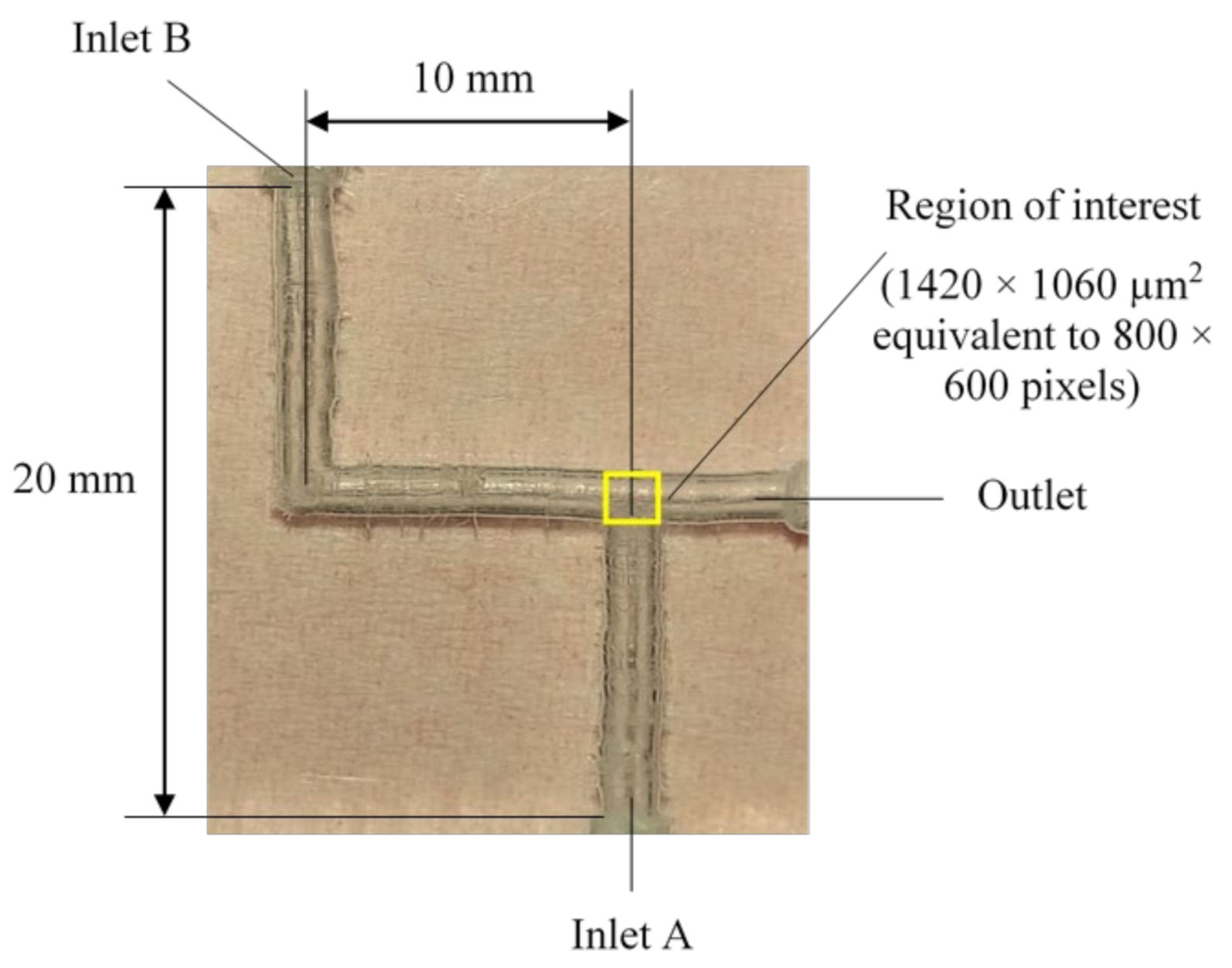
The offset T-junction microfluidic channel was fabricated using 4 units of Poly (methyl methacrylate) (PMMA) having thickness of 6 mm. To cut the section forming 20 mm length and 25 mm height cuboid, the PMMA sheet was machined using a 40 W CO2 laser (Model: Fabool, smartDIYs Inc., Tennessee, Japan). The resultant debris was cleaned using clean-room tissue. The PMMA was then drilled using an electric mini drill to form the microchannel shape with inlet and outlet radiuses of 400 µm, 500 µm, 750 µm and 1000 µm. Fluids of two different densities entered from inlet A and B separately, then moved into the channels and mixed at the junction highlighted by the yellow-coloured box (Figure 1).
2.2. Experimental Setup and Micro-PIV Processing
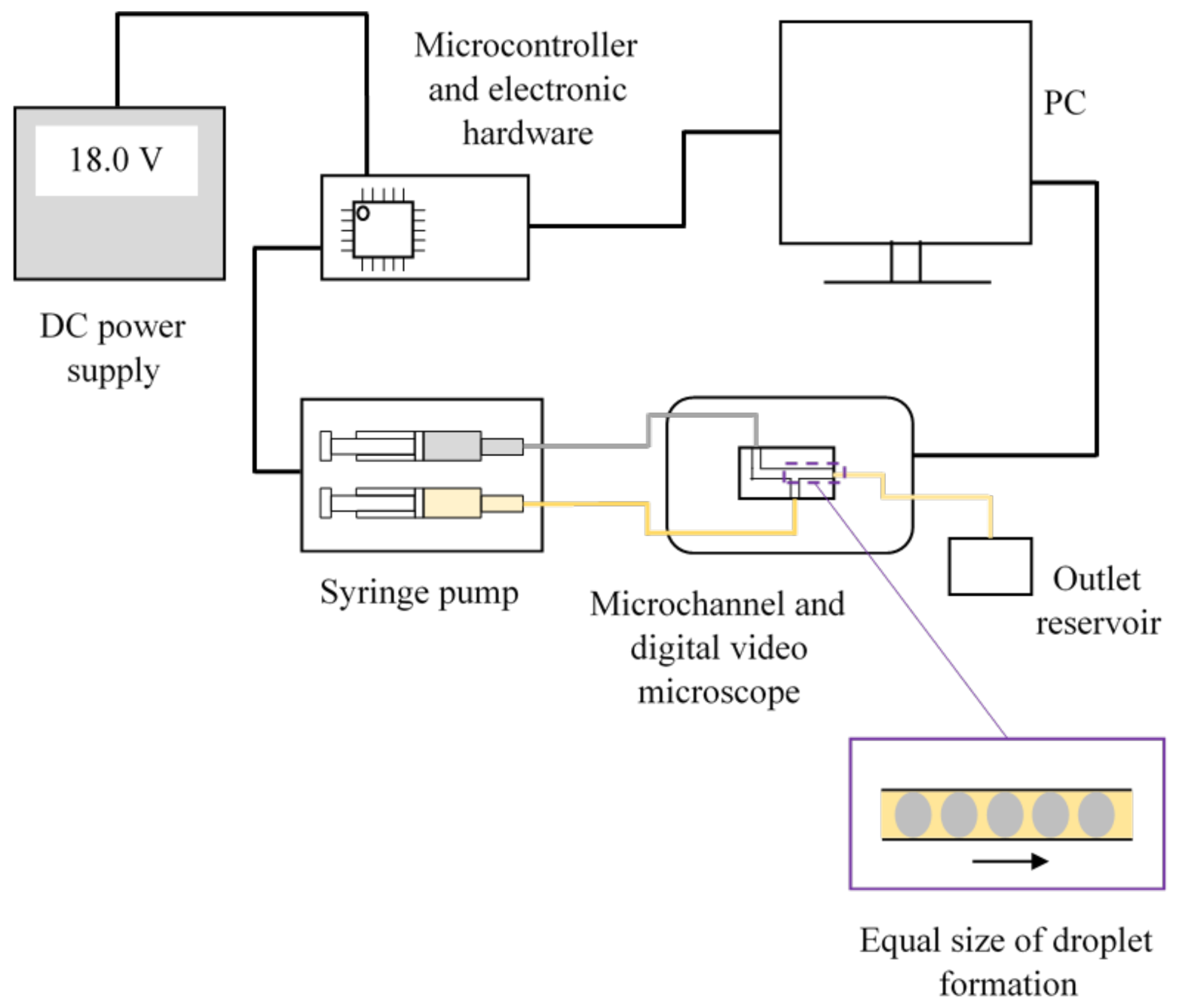
The schematic diagram of a microfluidic channel and the associated optical imaging measurement system is shown in Figure 2 along with the fluid driving mechanism. A digital video microscope (Model: MD500, AmScope, Irvine, CA, USA) having 4× magnification was used to capture the droplet behaviours focused at the junction of the microfluidic channel, with an image resolution of 800 × 600 pixels. A two-phase stepper motor (Model: NEMA 17, StepperOnline Inc., New York, NY, USA) driven lead screw was used to drive the syringes containing the different solutions. The syringe with 10 mL nominal capacity ±4% at room temperature was used for the setup. An Arduino Uno microcontroller was programmed to control stepper motor powered by a linear DC supply (Model: GPS-3030D, Good Will Instrument Co., Ltd., New Taipei City, Taiwan). Table 1 summarizes the input parameter setting maintained for all the experiments, including the setting of the microscope and initial flow rate.
The experiments originally used the Magnaglo® 14A fluorescent magnetic powder (mean particle size of 6 µm, manufactured by Magnaflux, Glenview, IL, USA) suspended in Carrier II (density of 802.837 kg/m3, dynamic viscosity of 0.0026 Pa·s at 38 °C, manufactured by Magnaflux, Glenview, IL, USA) at the dispersed phase. However, due to its fast settling in the oil, the preliminary experiments were unsuccessful. Hence, food-grade palm olein, having a density of 917 kg/m3 and viscosity of 7.97 × 10⁻² Pa·s [35], and distilled water (density of 997 kg/m3, viscosity of 8.90 × 10⁻⁴ Pa·s at ambient temperature) seeded with polystyrene microspheres particles (manufactured by Thermo Scientific™ 4210A, San Francisco, CA, USA) were injected into inlet A and inlet B, respectively, for different radiuses of offset T-junction microchannels. Food-grade palm olein was chosen for this study because it is one of the most commonly used oils in the household and food industries [36], and also has a high stability index [36] in the emulsification process. The suspension containing seeding particles (Table 2) and distilled water had a ratio of 1:4 for each experiment. The food-grade palm olein and the seeding particles were assumed to have the same density and dynamic viscosity as distilled water. These particles do not affect the palm olein because they are suspended in water. Due to the particles’ small size, and minimal density difference between the particles (1050 kg/m3) and water (997 kg/m3), they are assumed to faithfully follow the flow of water [18,37].
As the densities of the two fluids (food-grade olein and distilled water) were different, the properties of the distilled water were taken as the reference.
By adopting time-resolved as the image sequencing style in micro-PIV for MATLAB software [39,40], the flow patterns of the fluids were obtained. The region of interest was set to the whole area of the 800 × 600 pixels frame. The physical dimension of the region is 1420 × 1060 µm2 (see Figure 1). Therefore, the resolution is 1.77 µm × 1.77 µm per pixel, respectively. For image pre-processing, contrast limited adaptive histogram equalization (CLAHE) was applied to the images for visibility enhancement [41]. It is noted that the average seeding density is 5 particles per 32 × 32 window, while the threshold parameter for the signal-to-noise ratio was set at 1.5. The spatial resolution is defined by the size of the window of the interrogation spot and out-of-plane resolution [42]. In the case of volume illumination, the depth of focus of the microscope objective defines the measurement region [43]. By overlapping the interrogation spots with 50%, the resulting velocity fields have a spatial resolution of 28.4 μm × 28.4 μm × 55.5 μm. Then, the images were processed by cross-correlation function in order to obtain the raw velocity vectors of the liquids. To compensate for aberration [37,44], the calibration was performed using the image of 10 µm polystyrene microsphere flowing inside the microchannel, which resulted to 6 × 6 pixels based on 4× magnification of digital video microscope. The vector validation was conducted in order to eliminate some incorrect vectors remaining from noise peaks in the correlation function.
3. Results and Discussion
3.1. Evolution of Water Droplets at the Intersection of the Offset T-Junction Microchannel
In general, less viscous water flows faster than more viscous oil. However, when both solutions were experimented on within the microchannel, the hydrophobic coating on the walls of the PMMA channel [45] created a small air gap between the inside wall of the channel and the outer surface of the liquids [46]. The air gap around the more viscous liquid is larger, which allowed food-grade palm olein to move through the channel faster than the less viscous distilled water.
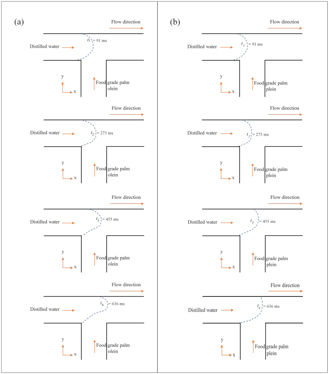
Figure 3 shows the growth of water droplets at the junction in an offset T-microchannel at t1 = 91 ms until t4 = 636 ms. The droplet in the microchannel with a radius of 400 µm evolved faster over time compared to the droplet in the channel with a radius of 750 µm, and at t4 = 636 ms, the front tip of droplet started to exceed the junction point. This growth pattern of the droplet was found to be similar to the ones in the channel with a radius of 500 µm. However, for the channel with a radius of 750 µm, the evolution of the water droplet was much slower as time passed, and the droplet was still within the junction area and can be seen at t4 = 636 ms. In terms of droplet size, the droplet becomes larger as the size of the microchannel increases. The water droplet is rounder and more solid-shaped within the microchannel’s radius of 750 µm. Its size is less than or nearly equal to the microchannel’s width. Both channels showed that when the droplet reached the junction, the oil pushed the water droplet upwards and caused an irregular shape at the bottom of the droplet, as can be seen at t3 = 455 ms. At this point, the droplet was likely starting to enter the break-up process. The droplet expanded mainly in the radial direction and slightly in the axial direction [1]. Hence, the length increases gradually while the width increases moderately. This point is named the thread expansion stage, and the period is called expansion time [1]. As it reached t = t4, the cross-flowing liquids drove the thread in its axial direction and a visible neck formed. The droplet in the microchannel with a radius of 400 µm is faster to split and to break up compared to the 750 µm channel.
3.2. Experimental Velocity of Water Droplets at the Intersection of Offset T-Junction Microchannel
Figure 4 shows the motion of droplets in the offset T-junction microchannels from t = 91 ms to t = 455 ms, while Table 3 summarizes the minimal difference in theoretical and experimental velocity of the water droplets. Time t = 91 ms and t = 455 ms were chosen because the front tip of the droplets for all channels still can be seen at this range of time. The front tip of the droplets is exceeded the field of view at t = 636 ms in the case of the microchannel with radiuses of 400 µm and 500 µm. An increase in the radius of the offset T-junction microchannel leads to a decrease in the droplet’s velocity. Velocity decreases when the cross-sectional area increases [47]. This is a consequence of the continuity equation. If the flow rate is held constant, when the area decreases, the velocity must increase proportionally. Based on Table 3, the experimental data have proved this theory, where the microchannel with a radius of 400 µm has a higher water droplet velocity than the channel with a radius of 750 µm.
The experimental velocity of the distilled water phase is also in keeping with that found within the theoretical velocity. The surface roughness of the channel walls might affect the liquids’ flows, which cause 0.06 mm/s difference in the theoretical and experimental velocity of the distilled water phase within a microchannel radius of 500 µm. However, the actual roughness of the walls could not be quantified. For the inlet and outlet radius of the offset T-junction microchannel = 1000 µm, the experimental velocity could not be determined due to the fact that the droplet was forming outside the field of view as the image was captured at the junction.
3.3. Internal Velocity Profile of Generated Water Droplets in Offset T-Junction Microchannel
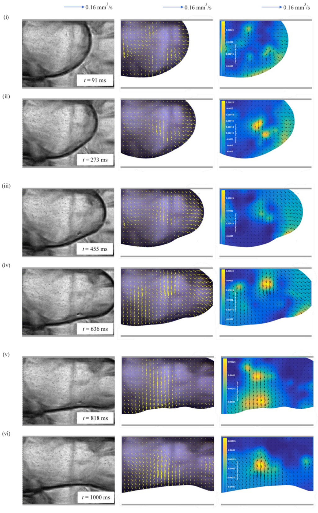
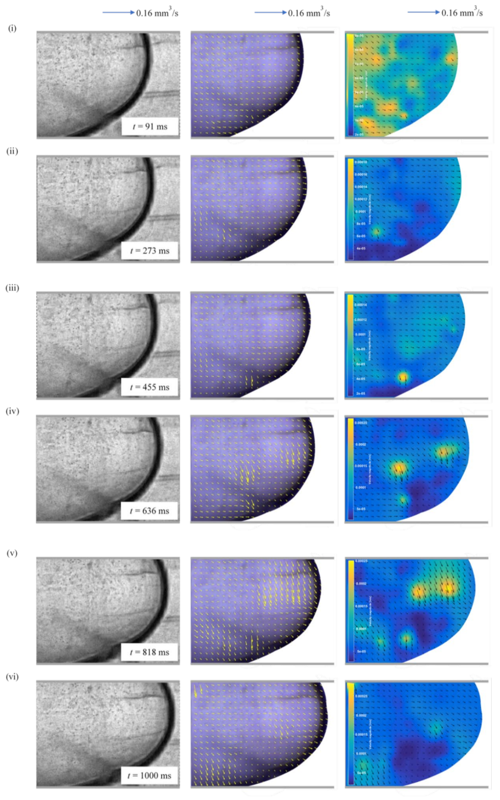
Figure 5, Figure 6, Figure 7 and Figure 8 show pre-processing images, vector analysis and also velocity magnitude analysis performed by a micro-PIV technique via MATLAB software for the droplet flow and slug flow pattern. As the water is in the dispersed phase, the hydrophobic coating promotes these dispersed flows in which the water phase must wet the wall of the microchannel [46].
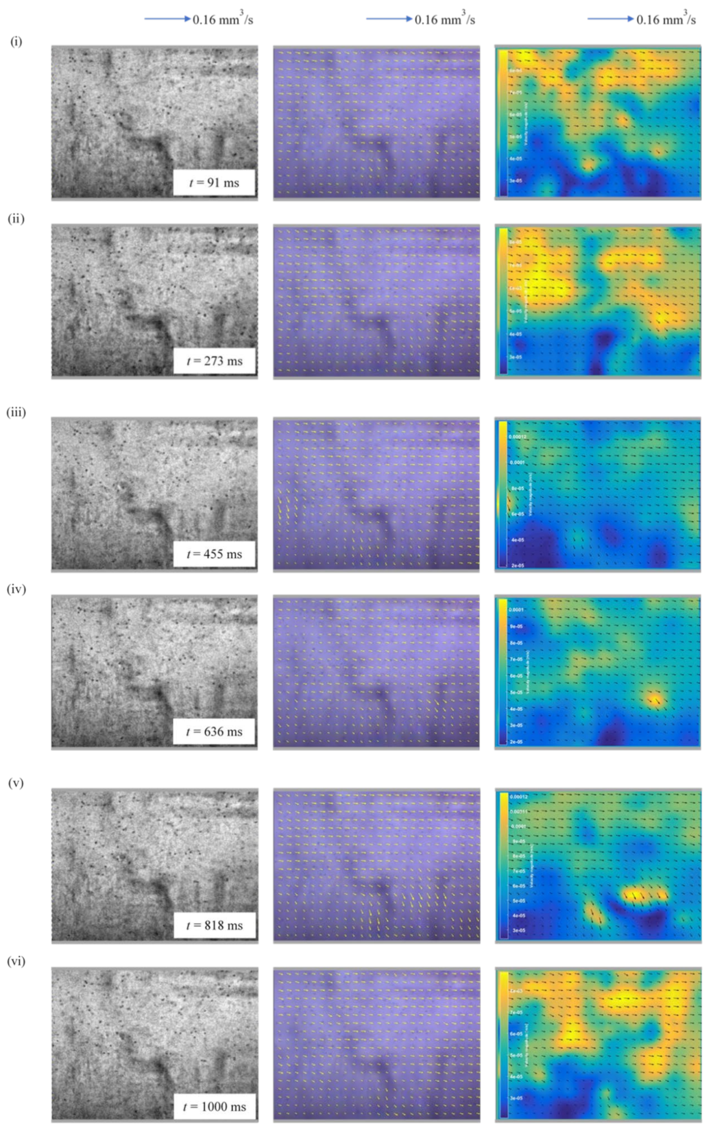
The pattern of the flow involving droplets as shown in Figure 5, Figure 6 and Figure 7 can be characterized by the sub-channel-sized droplets [34]. The flow within these droplets is guided forward at the interfaces to the right end of the microchannels, where the water droplets are bypassed by the continuous oil phase. The formation of such droplets, having diameters less than the channel diameter, are generated at low dispersed and high continuous phase flow rates. In such conditions, the inertial force input at the higher flow rate of the continuous phase is high enough to break down the dispersed phase into smaller droplets with lesser resistance posed by the dispersed phase at a lower flow rate. Meanwhile, for the slug flow pattern, which is likely to be the flow behaviour for the microchannel with a radius of 1000 µm (Figure 8), the slug occupied almost the whole cross-section of the microchannel with a very thin layer of the oil phase between the slug and the wall of the offset T-junction microchannel. This behaviour fit well in Darekar, Singh [34] generalized flow regime map. It is evident from this discussion that changing the channel size has a significant impact on the slug size. In contrast to the smaller offset T-junction microchannel, bigger channels produce larger slugs. All of the microchannels exhibit same slug size behaviours in relation to flow velocity [32]. However, the shear stress is not significant in this regime, and the interfacial tension, along with the pressure gradient, results in the breakup of the dispersed phase into slug. The interfacial tension could not support and endure the pressure gap between inside and outside the interface at the droplet’s tail [28]. This differential pressure increased prior to the neck regime, squeezing the interface and, consequently, forced the rear tip or interface to break, resulting in the formation of a droplet. Resultantly, the slug growth leads to the obstruction to the continuous phase flow [34].
In terms of the microchannel’s size affecting the size of droplet, based from Figure 5, Figure 6 and Figure 7, the droplets’ size increases with an increase in the radius of the microchannels [32]. In the case of small differences between the offset T-junction microchannels, i.e., radiuses of 400 µm and 500 µm, there is no major difference in droplets’ sizes that can be spotted in Figure 5 and Figure 6. However, with a further increase in the microchannel’s radius to 750 µm (Figure 7), the water droplet’s size with respect to flow velocity increases significantly. For the microchannel with a radius of 1000 µm (Figure 8), the droplet’s volume cannot be seen due to the limit of field of view and the exceedance of the observation area. From this discussion, it is clear that the change in the offset T-junction microchannel’s radius exerts a major influence on the water droplet’s size.
On the other hand, the flow velocity vectors determined by micro-PIV are displayed as small arrows. The key features of the flow are illustrated by larger arrows for better visualization. At t = 91 ms and t = 1000 ms, the microchannel with a radius of 750 µm (Figure 7) has an average velocity of 0.055 mm/s and 0.15 mm/s, which is 2.7 and 1.3 times smaller than the average velocity of the microchannel with a radius of 500 µm (Figure 6), respectively. This is because in a bigger channel, the oil phase takes a longer time to break down the water phase into longer slugs. The interfacial area was decreased as channel size was increased. In contrast to that, for a smaller channel, an increase in the velocity with respect to time increases its inertial force which leads to the enhancement in its tendency to break down the water phase into smaller droplet form. In short, increasing the channel’s size and cross-sectional area decrease the liquid’s velocity compared to the ones in the smaller channel. This also can be proved by referring to the Hagen–Poiseuille equation [48] below:
where QHP is flow rate, R is the channel’s radius, ∆p is the pressure drop between the inlet and outlet, μ is the dynamic viscosity of the fluid and L is the channel’s length.
QHP = (π × R^4 × ∆p)/(8 × μ × L)
The velocity could then be shown as,
where vHP is the average velocity and A is the channel’s cross-sectional area.
vHP = QHP/ A = (R^2 × ∆p)/(8 × μ × L)
If Qexp is to be the flow rate measured in the experiment, the velocity can, thus, be written as,
vexp = Qexp/A
The highest velocity which coloured in yellow region in velocity magnitude analysis is largely due to the vortex which localised towards the edge of the droplet, as the droplet grew bigger and the particles also moved to the edge. The interfacial tension between the droplet and the continuous oil phase pulls the resulting interface sideways more firmly, causing powerful vortex motions within the water droplet. The shear force causes these strong vortex motions within the droplet, located away from the centre to the edge of the front inner surface, deflecting the accelerated dispersed water phase [30]. Since gravitational forces have no significant impact in microfluidics, it can be concluded that the central region of the inner droplets exhibits low velocities, while the regions near the channel boundaries have higher velocities magnitude [26]. There might be minimal errors in the readings due to the channel’s inner geometry and its surface roughness during the fabrication process.
4. Conclusions
The present work aims at studying the behaviours of distilled water droplet formation suspended in food-grade palm olein at the interfacial surface in offset T-junction microchannels, having radiuses of 400 µm, 500 µm, 750 µm and 1000 µm, by means of micro-PIV software. The different sizes of inlet and outlet radiuses of microfluidic channels were affecting the flow behaviours of the generated water droplets. The experimental results show that increasing the radius of the offset T-junction microchannel leads to an increase in the cross-sectional area and the decrease in the distilled water phase’s velocity. The microchannel with a radius of 400 µm has a higher distilled water phase velocity than the channel with a radius of 750 µm. Furthermore, the experimental velocity of the distilled water phase is in agreement with theoretical values, i.e., radiuses of 400 µm, 500 µm and 750 µm microchannels have a minimal difference of 0.008 mm/s, 0.06 mm/s and 0.004 mm/s, respectively. For the radius of the offset T-junction microchannel = 1000 µm, the experimental velocity could not be determined due to the fact that the droplet was forming outside of the field of view as the image was captured at the junction. The size of the droplets increased as the radius of the microchannel increased, and they are nearly equal to the microchannel’s width. At t = 1000 ms, the average velocity of the channel with a radius of 400 µm decreased slightly to 0.12 mm/s, which may be due to the roughness on the channel’s surface, while the other channels showed a good and maintained average velocity. This concludes that the vector and velocity magnitude data are in agreement with the Hagen–Poiseuille flow equation, meaning that a small increase in the channel’s size yields a significant increase in the overall flow of a liquid.
Author Contributions
Conceptualization and methodology, K.F.T. and H.R.; formal analysis and investigation, H.R.; data curation H.R.; writing—original draft preparation, H.R. and N.A.S.; writing—review and editing, K.F.T., N.A.S., S.M.; supervision and funding acquisition, K.F.T. All authors have read and agreed to the published version of the manuscript.
Funding
This research was funded by Universiti Malaysia Sarawak, grant number F02/PGRG/2043/2020 and UNIMAS Zamalah Postgraduate Scholarship.
Institutional Review Board Statement
Not applicable.
Informed Consent Statement
Not applicable.
Data Availability Statement
The data presented in this study are available on request from the corresponding author.
Conflicts of Interest
The authors declare no conflict of interest.
References
- Fu, T.; Ma, Y.; Funfschilling, D.; Li, H.Z. Bubble formation and breakup mechanism in a microfluidic flow-focusing device. Chem. Eng. Sci. 2009, 64, 2392–2400. [Google Scholar] [CrossRef]
- Guenther, A.; Jhunjhunwala, M.; Thalmann, M.; Schmidt, A.M.A.; Jensen, K.F. Micromixing of Miscible Liquids in Segmented Gas−Liquid Flow. Langmuir 2005, 21, 1547–1555. [Google Scholar] [CrossRef]
- Wang, J.; Wang, J.; Feng, L.; Lin, T. Fluid mixing in droplet-based microfluidics with a serpentine microchannel. RSC Adv. 2015, 5, 104138–104144. [Google Scholar] [CrossRef]
- Wu, B.; Von Der Ecken, S.; Swyer, I.; Li, C.; Jenne, A.; Vincent, F.; Schmidig, D.; Kuehn, T.; Beck, A.; Busse, F.; et al. Rapid Chemical Reaction Monitoring by Digital Microfluidics-NMR: Proof of Principle Towards an Automated Synthetic Discovery Platform. Angew. Chem. Int. Ed. 2019, 58, 15372–15376. [Google Scholar] [CrossRef] [PubMed]
- Chen, C.-H.; Shah, R.K.; Abate, A.R.; Weitz, D.A. Janus Particles Templated from Double Emulsion Droplets Generated Using Microfluidics. Langmuir 2009, 25, 4320–4323. [Google Scholar] [CrossRef] [PubMed]
- Vladisavljević, G.T.; Al Nuumani, R.; Nabavi, S.A. Microfluidic Production of Multiple Emulsions. Micromachines 2017, 8, 75. [Google Scholar] [CrossRef]
- Teh, S.-Y.; Lin, R.; Hung, L.-H.; Lee, A.P. Droplet microfluidics. Lab Chip 2008, 8, 198–220. [Google Scholar] [CrossRef]
- Joensson, H.N.; Svahn, H.A. Droplet Microfluidics-A Tool for Single-Cell Analysis. Angew. Chem. Int. Ed. 2012, 51, 12176–12192. [Google Scholar] [CrossRef]
- Li, C.; Boban, M.; Tuteja, A. Open-channel, water-in-oil emulsification in paper-based microfluidic devices. Lab Chip 2017, 17, 1436–1441. [Google Scholar] [CrossRef]
- Shah, R.K.; Shum, H.C.; Rowat, A.C.; Lee, D.; Agresti, J.J.; Utada, A.S.; Chu, L.-Y.; Kim, J.-W.; Fernandez-Nieves, A.; Martinez, C.; et al. Designer emulsions using microfluidics. Mater. Today 2008, 11, 18–27. [Google Scholar] [CrossRef]
- Thurgood, P.; Baratchi, S.; Arash, A.; Pirogova, E.; Jex, A.R.; Khoshmanesh, K. Asynchronous generation of oil droplets using a microfluidic flow focusing system. Sci. Rep. 2019, 9, 1–11. [Google Scholar] [CrossRef]
- Deng, C.; Huang, W.; Wang, H.; Cheng, S.; He, X.; Xu, B. Preparation of micron-sized droplets and their hydrodynamic behavior in quiescent water. Braz. J. Chem. Eng. 2018, 35, 709–720. [Google Scholar] [CrossRef] [Green Version]
- Yao, J.; Lin, F.; Kim, H.S.; Park, J. The Effect of Oil Viscosity on Droplet Generation Rate and Droplet Size in a T-Junction Microfluidic Droplet Generator. Micromachines 2019, 10, 808. [Google Scholar] [CrossRef] [Green Version]
- Zhu, P.; Wang, L. Passive and active droplet generation with microfluidics: A review. Lab Chip 2017, 17, 34–75. [Google Scholar] [CrossRef]
- Ringkai, H.; Tamrin, K.; Sheikh, N.; Barroy, P. Characterization of dissimilar liquids mixing in T-junction and offset T-junction microchannels. Proc. Inst. Mech. Eng. Part E J. Process. Mech. Eng. 2021. [Google Scholar] [CrossRef]
- Colucci, G.; Santamaria-Echart, A.; Silva, S.C.; Fernandes, I.P.M.; Sipoli, C.C.; Barreiro, M.F. Development of Water-in-Oil Emulsions as Delivery Vehicles and Testing with a Natural Antimicrobial Extract. Molecules 2020, 25, 2105. [Google Scholar] [CrossRef]
- Zhu, Q.; Pan, Y.; Jia, X.; Li, J.; Zhang, M.; Yin, L. Review on the Stability Mechanism and Application of Water-in-Oil Emulsions Encapsulating Various Additives. Compr. Rev. Food Sci. Food Saf. 2019, 18, 1660–1675. [Google Scholar] [CrossRef]
- Santiago, J.G.; Wereley, S.T.; Meinhart, C.D.; Beebe, D.J.; Adrian, R.J. A particle image velocimetry system for microfluidics. Exp. Fluids 1998, 25, 316–319. [Google Scholar] [CrossRef]
- Shinohara, K.; Sugii, Y.; Aota, A.; Hibara, A.; Tokeshi, M.; Kitamori, T.; Okamoto, K. High-speed micro-PIV measurements of transient flow in microfluidic devices. Meas. Sci. Technol. 2004, 15, 1965–1970. [Google Scholar] [CrossRef]
- Hagsäter, S.M.; Jensen, T.G.; Bruus, H.; Kutter, J.P. Acoustic resonances in microfluidic chips: Full-image micro-PIV experiments and numerical simulations. Lab Chip 2007, 7, 1336–1344. [Google Scholar] [CrossRef] [Green Version]
- Omori, T.; Imai, Y.; Kikuchi, K.; Ishikawa, T.; Yamaguchi, T. Hemodynamics in the Microcirculation and in Microfluidics. Ann. Biomed. Eng. 2014, 43, 238–257. [Google Scholar] [CrossRef] [PubMed]
- Campo-Deaño, L. Fluid-flow characterization in microfluidics. In Complex Fluid-Flows in Microfluidics; Galindo-Rosales, F.J., Ed.; Springer: Berlin/Heidelberg, Germany, 2018; pp. 53–71. [Google Scholar]
- Oishi, M.; Kinoshita, H.; Fujii, T.; Oshima, M. Simultaneous measurement of internal and surrounding flows of a moving droplet using multicolour confocal micro-particle image velocimetry (micro-PIV). Meas. Sci. Technol. 2011, 22. [Google Scholar] [CrossRef]
- Jakiela, S.; Korczyk, P.M.; Makulska, S.; Cybulski, O.; Garstecki, P. Discontinuous Transition in a Laminar Fluid Flow: A Change of Flow Topology inside a Droplet Moving in a Micron-Size Channel. Phys. Rev. Lett. 2012, 108. [Google Scholar] [CrossRef] [PubMed]
- Ma, S.; Sherwood, J.M.; Huck, W.T.S.; Balabani, S. On the flow topology inside droplets moving in rectangular microchannels. Lab Chip 2014, 14, 3611–3620. [Google Scholar] [CrossRef] [Green Version]
- Ma, S.; Sherwood, J.M.; Huck, W.T.S.; Balabani, S. The microenvironment of double emulsions in rectangular microchannels. Lab Chip 2015, 15, 2327–2334. [Google Scholar] [CrossRef] [Green Version]
- Hein, M.; Moskopp, M.; Seemann, R. Flow field induced particle accumulation inside droplets in rectangular channels. Lab Chip 2015, 15, 2879–2886. [Google Scholar] [CrossRef]
- Liu, Z.; Zhang, L.; Pang, Y.; Wang, X.; Li, M. Micro-PIV investigation of the internal flow transitions inside droplets traveling in a rectangular microchannel. Microfluid. Nanofluidics 2017, 21, 180. [Google Scholar] [CrossRef]
- Kinoshita, H.; Kaneda, S.; Fujii, T.; Oshima, M. Three-dimensional measurement and visualization of internal flow of a moving droplet using confocal micro-PIV. Lab Chip 2007, 7, 338–346. [Google Scholar] [CrossRef]
- Jin, B.-J.; Yoo, J.Y. Visualization of droplet merging in microchannels using micro-PIV. Exp. Fluids 2012, 52, 235–245. [Google Scholar] [CrossRef]
- Shen, F.; Li, Y.; Liu, Z.; Li, X. (James) Study of flow behaviors of droplet merging and splitting in microchannels using Micro-PIV measurement. Microfluid. Nanofluidics 2017, 21. [Google Scholar] [CrossRef] [Green Version]
- Kashid, M.N.; Agar, D.W. Hydrodynamics of liquid–liquid slug flow capillary microreactor: Flow regimes, slug size and pressure drop. Chem. Eng. J. 2007, 131, 1–13. [Google Scholar] [CrossRef]
- Salim, A.; Fourar, M.; Pironon, J.; Sausse, J. Oil–water two-phase flow in microchannels: Flow patterns and pressure drop measure-ments. Can. J. Chem. Eng. 2008, 86, 978–988. [Google Scholar] [CrossRef]
- Darekar, M.; Singh, K.K.; Mukhopadhyay, S.; Shenoy, K.T. Liquid–Liquid Two-Phase Flow Patterns in Y-Junction Microchannels. Ind. Eng. Chem. Res. 2017, 56, 12215–12226. [Google Scholar] [CrossRef]
- Ahmad, A.; Siddique, B.M.; Ibrahim, M.H.; Hena, S.; Rafatullah, M. Physico-chemical properties of blends of palm olein with other vegetable oils. Grasas Aceites 2010, 61, 423–429. [Google Scholar] [CrossRef]
- Idris, C.A.C.; Sundram, K.; Razis, A.F.A. Effect of Consumption Heated Oils with or without Dietary Cholesterol on the Devel-opment of Atherosclerosis. Nutrients 2018, 10, 1527. [Google Scholar] [CrossRef] [Green Version]
- Tamrin, K.; Rahmatullah, B.; Samuri, S. An experimental investigation of three-dimensional particle aggregation using digital holographic microscopy. Opt. Lasers Eng. 2015, 68, 93–103. [Google Scholar] [CrossRef]
- Turner, A.; Yandrofski, K.; Telikepalli, S.; King, J.; Heckert, A.; Filliben, J.; Ripple, D.; Schiel, J.E. Development of orthogonal NISTmAb size heterogeneity control methods. Anal. Bioanal. Chem. 2018, 410, 2095–2110. [Google Scholar] [CrossRef] [Green Version]
- Thielicke, W.; Stamhuis, E.J. PIVlab—Towards User-friendly, Affordable and Accurate Digital Particle Image Velocimetry in MATLAB. J. Open Res. Softw. 2014, 2, e30. [Google Scholar] [CrossRef] [Green Version]
- Thielicke, W. The Flapping Flight of Birds: Analysis and Application. Ph.D. Thesis, University of Groningen, Groningen, The Netherlands, October 2014. [Google Scholar]
- Yadav, G.; Maheshwari, S.; Agarwal, A. Contrast limited adaptive histogram equalization based enhancement for real time video system. In Proceedings of the 2014 International Conference on Advances in Computing, Communications and Informatics (ICACCI), Delhi, India, 24–27 September 2014; pp. 2392–2397. [Google Scholar]
- Meinhart, C.D.; Wereley, S.T.; Santiago, J.G. PIV measurements of a microchannel flow. Exp. Fluids 1999, 27, 414–419. [Google Scholar] [CrossRef]
- Meinhart, C.D.; Wereley, S.T.; Gray, M.H.B. Volume illumination for two-dimensional particle image velocimetry. Meas. Sci. Technol. 2000, 11, 809–814. [Google Scholar] [CrossRef]
- Tamrin, K.; Rahmatullah, B.; Samuri, S. Aberration compensation of holographic particle images using digital holographic mi-croscopy. J. Mod. Opt. 2015, 62, 701–711. [Google Scholar] [CrossRef] [Green Version]
- Wang, B.; Zhang, Y.; Song, J.; Wang, Z. Investigation and Prediction on Regulation of Hydrophobicity of Polymethyl Methacrylate (PMMA) Surface by Femtosecond Laser Irradiation. Coatings 2020, 10, 386. [Google Scholar] [CrossRef] [Green Version]
- Vuckovac, M.; Backholm, M.; Timonen, J.V.I.; Ras, R.H.A. Viscosity-enhanced droplet motion in sealed superhydrophobic capillaries. Sci. Adv. 2020, 6, eaba5197. [Google Scholar] [CrossRef] [PubMed]
- Pang, Y.; Kim, H.; Liu, Z.; Stone, H.A. A soft microchannel decreases polydispersity of droplet generation. Lab Chip 2014, 14, 4029–4034. [Google Scholar] [CrossRef] [Green Version]
- Liu, Z.-M.; Pang, Y. Effect of the size and pressure on the modified viscosity of water in microchannels. Acta Mech. Sin. 2015, 31, 45–52. [Google Scholar] [CrossRef]
Figure 1.
Fabricated offset T-junction microchannel with an inlet and outlet radius of 750 µm.

Figure 2.
Schematic diagram of experimental setup.

Figure 3.
The evolution of water droplets for offset T-junction microchannels with radiuses of (a) 400 µm, and (b) 750 µm at t1 = 91 ms until t4 = 636 ms.
Figure 3.
The evolution of water droplets for offset T-junction microchannels with radiuses of (a) 400 µm, and (b) 750 µm at t1 = 91 ms until t4 = 636 ms.

Figure 4.
The motion of water droplets after 364 ms within radiuses of (a) 400 µm, (b) 500 µm, and (c) 750 µm offset T-junction microchannels.
Figure 4.
The motion of water droplets after 364 ms within radiuses of (a) 400 µm, (b) 500 µm, and (c) 750 µm offset T-junction microchannels.

Figure 5.
Pre-processing image, vector and velocity magnitude for the offset T-junction microchannel with a radius of 400 µm at (i) 91 ms, (ii) 273 ms, (iii) 455 ms, (iv) 636 ms, (v) 818 ms and (vi) 1000 ms.
Figure 5.
Pre-processing image, vector and velocity magnitude for the offset T-junction microchannel with a radius of 400 µm at (i) 91 ms, (ii) 273 ms, (iii) 455 ms, (iv) 636 ms, (v) 818 ms and (vi) 1000 ms.

Figure 6.
Pre-processing image, vector and velocity magnitude for the offset T-junction microchannel with a radius of 500 µm at (i) 91 ms, (ii) 273 ms, (iii) 455 ms, (iv) 636 ms, (v) 818 ms and (vi) 1000 ms.
Figure 6.
Pre-processing image, vector and velocity magnitude for the offset T-junction microchannel with a radius of 500 µm at (i) 91 ms, (ii) 273 ms, (iii) 455 ms, (iv) 636 ms, (v) 818 ms and (vi) 1000 ms.

Figure 7.
Pre-processing image, vector and velocity magnitude for the offset T-junction microchannel with a radius of 750 µm at (i) 91 ms, (ii) 273 ms, (iii) 455 ms, (iv) 636 ms, (v) 818 ms and (vi) 1000 ms.
Figure 7.
Pre-processing image, vector and velocity magnitude for the offset T-junction microchannel with a radius of 750 µm at (i) 91 ms, (ii) 273 ms, (iii) 455 ms, (iv) 636 ms, (v) 818 ms and (vi) 1000 ms.

Figure 8.
Pre-processing image, vector and velocity magnitude for the offset T-junction microchannel with a radius of 1000 µm at (i) 91 ms, (ii) 273 ms, (iii) 455 ms, (iv) 636 ms, (v) 818 ms and (vi) 1000 ms.
Figure 8.
Pre-processing image, vector and velocity magnitude for the offset T-junction microchannel with a radius of 1000 µm at (i) 91 ms, (ii) 273 ms, (iii) 455 ms, (iv) 636 ms, (v) 818 ms and (vi) 1000 ms.


Table 1.
Controlled parameters.
| Parameter | Value |
|---|---|
| Exposure time | 3.906 ms |
| Colour temperature | 5547 |
| Frame rate | 21.8 f/s |
| Resolution | 800 × 600 pixels |
| Motor step | 5 |
| Flow rate of liquid at the inlets | 0.16 mm3/s |
Table 2.
Specification of seeding particle [38].
Table 2.
Specification of seeding particle [38].
| Composition/Material | Polystyrene |
|---|---|
| Diameter | 10 µm ± 0.08 µm |
| Concentration | 0.2% solids |
| Density | 1050 kg/m3 |
| Refractive index | 1.59 at 589 nm (25 °C) |
Table 3.
Theoretical and experimental velocity of water droplets.
| Inlet and Outlet Radiuses of Offset T-Junction Micro-Channel (µm) | Theoretical Velocity of Water Droplets Based on Reynolds Number (mm/s) | Experimental Velocity of Water Droplets (mm/s) |
|---|---|---|
| 400 | 0.322 | 0.330 |
| 500 | 0.206 | 0.266 |
| 750 | 0.092 | 0.096 |
| 1000 | 0.051 |
Publisher’s Note: MDPI stays neutral with regard to jurisdictional claims in published maps and institutional affiliations. |
© 2021 by the authors. Licensee MDPI, Basel, Switzerland. This article is an open access article distributed under the terms and conditions of the Creative Commons Attribution (CC BY) license (https://creativecommons.org/licenses/by/4.0/).
Share and Cite
MDPI and ACS Style
Ringkai, H.; Tamrin, K.F.; Sheikh, N.A.; Mohamaddan, S. Evolution of Water-in-Oil Droplets in T-Junction Microchannel by Micro-PIV. Appl. Sci. 2021, 11, 5289. https://0-doi-org.brum.beds.ac.uk/10.3390/app11115289
AMA Style
Ringkai H, Tamrin KF, Sheikh NA, Mohamaddan S. Evolution of Water-in-Oil Droplets in T-Junction Microchannel by Micro-PIV. Applied Sciences. 2021; 11(11):5289. https://0-doi-org.brum.beds.ac.uk/10.3390/app11115289
Chicago/Turabian StyleRingkai, Hawa, Khairul Fikri Tamrin, Nadeem Ahmed Sheikh, and Shahrol Mohamaddan. 2021. "Evolution of Water-in-Oil Droplets in T-Junction Microchannel by Micro-PIV" Applied Sciences 11, no. 11: 5289. https://0-doi-org.brum.beds.ac.uk/10.3390/app11115289
Note that from the first issue of 2016, this journal uses article numbers instead of page numbers. See further details here.