
Crawling Magnetic Robot to Perform a Biopsy in Tubular Environments by Controlling a Magnetic Field


Graduate School of Mechanical Engineering, Hanyang University, Seoul 04763, Korea
*
Author to whom correspondence should be addressed.
Appl. Sci. 2021, 11(11), 5292; https://0-doi-org.brum.beds.ac.uk/10.3390/app11115292
Submission received: 14 May 2021
/
Revised: 30 May 2021
/
Accepted: 4 June 2021
/
Published: 7 June 2021
(This article belongs to the Special Issue Micro-Robotics)
Abstract
:We developed a crawling magnetic robot (CMR), which can stably navigate and perform biopsies remotely in tubular environments by controlling a magnetic field. The CMR is composed of a crawling part and a biopsy part. The crawling part allows the CMR to crawl forward and backward via an asymmetric friction force generated by an external precessional magnetic field. The biopsy part closes or opens the cover of a needle to use the biopsy needle selectively with the control of the external precessional magnetic field. The cover of the biopsy part prevents damage to the tubular environments because the biopsy needle is inside the cover while the CMR is navigating. We developed the design of the proposed CMR using magnetic torque constraints and a magnetic force constraint, and then we fabricated the CMR with three-dimensional printing technology. Finally, we conducted an experiment to measure the CMR’s puncturing force with a load cell and conducted an experiment in a Y-shaped watery glass tube with pseudo-tissue to verify the crawling motion, the uncovering and covering motion of the biopsy needle, and the CMR’s ability to extract tissue with the biopsy needle.
1. Introduction
A biopsy is a medical test to examine the presence or extent of a disease using tools such as a scalpel, a needle, or forceps to extract sample tissues from a patient’s body. While incisional or needle aspiration biopsies take a tissue sample close to human skin, endoscopic or cardiac biopsies collect sample tissues located deep inside the human body by inserting a long tube or catheter along the tubular structure of the human body. Conventional wired biopsies have low steering ability and controllability and mostly depend on the experience of physicians. Furthermore, there is a possibility of causing bacteremia due to the penetration of external bacteria into the patient’s body through the repeated insertion of the wires [1,2]. This may cause sepsis in patients who have low levels of immunity and could lead to death [3,4].
To overcome these problems, many researchers have studied wireless biopsy robots. Previous researchers have mainly explored biopsy robots for capsule endoscopes. However, such robots do not have their own propulsive force and are driven by the passive peristaltic motion of the intestine or by a micromotor [5,6,7]. One was designed to contain a microspike, which moves in and out of the robot using a slider–crank mechanism to perform safe biopsies [5]. Other researchers have proposed a magnetic robot that contains permanent magnets inside and can be controlled by using an external magnetic field to generate propulsive force instead of a micromotor and battery [8,9,10]. These magnetic robots include swimming robots with helical structures or biomechanical wings and inchworm and earthworm robots that locomote using wormlike motions [11,12,13,14,15,16,17,18,19]. These robots are useful for navigation, but it is difficult to maintain their positions, especially in the fluidic pulsatile environment of human blood vessels, where external forces are continually applied. To address this problem, several researchers have proposed a crawling robot operated in the tubular environments with a diameter of 9 to 21 mm [20,21,22]. Magnetic torque generates asymmetric frictional force between the legs of the crawling robot and the external wall, and this allows the crawling robot to navigate forward and backward. This is useful in performing other tasks because the crawling robot always maintains its position compared with other swimming robots, even without the application of an external magnetic field [20]. However, it is still difficult to generate other mechanical motions of the crawling robot without affecting the crawling motion itself, because the source of motion is the external magnetic field that is applied to the entire body of the crawling robot. Kim et al. proposed a crawling robot capable of selectively or simultaneously performed drilling motion in addition to its crawling motion by controlling the external precessional magnetic fields [21]. Recently, Lee et al. succeeded in achieving selective motion control of a crawling magnetic robot for wireless self-expandable stent delivery in narrowed tubular environments, in addition to crawling and drilling motions [22]. However, further research is still required to generate independent medical actions of the crawling robots such as drug deliveries or biopsies.
In this paper, we propose a crawling magnetic robot (CMR) that can wirelessly crawl and perform biopsies in tubular environments. The proposed CMR performs various mechanical actions under the control of an external magnetic field, such as a crawling motion with the needle covered, an uncovering motion to expose the needle, the insertion of the needle into the target area, and a covering motion of the needle after the collection of sample tissues. First, we explain the structure of the CMR and the magnetic manipulation method. Next, we describe the design and fabrication of the CMR considering the magnetic force constraint and magnetic torque constraints generated by external and internal magnetic fields due to the interactions between the permanent magnets of the CMR and the magnetic navigation system (MNS). We conducted an experiment to measure the CMR’s puncturing force with a load cell and performed an experiment using a Y-shaped watery glass tube to confirm the CMR’s crawling motion, uncovering and covering motion, and ability to collect sample tissue for biopsy.
2. Structure of the CMR
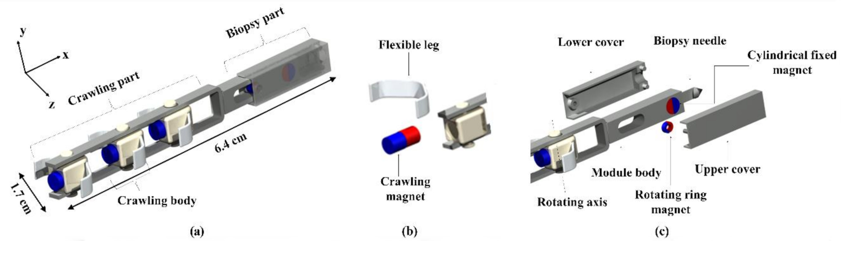
Figure 1 shows the structure of the proposed CMR, composed of a crawling part and a biopsy part. The crawling part is composed of three crawling bodies, and each crawling body contains an axially magnetized cylindrical magnet (CM) and two flexible legs. Each crawling body is freely rotatable with respect to the y-axis, and the motion of the crawling body is controlled using an external precessional magnetic field for stable navigation and needle insertion. The needle is designed in a hook shape, so when the puncturing process is completed, the sample tissue is detached automatically.
When the CMR reaches a target area, the CMR is designed to open the cover to expose a needle to a target area by controlling the external magnetic field. Once the cover opens, the forward crawling motion of the CMR inserts the needle into the target area. Then, the backward crawling motion takes the needle out of the target area and automatically closes the cover to carry the needle and sampled tissues independently of the crawling motion; this is accomplished by controlling the external magnetic field. The operation principle of the CMR with the application of an external magnetic field will be explained in Section 3.
3. Actuating Principle of the CMR
3.1. Magnetic Navigation System
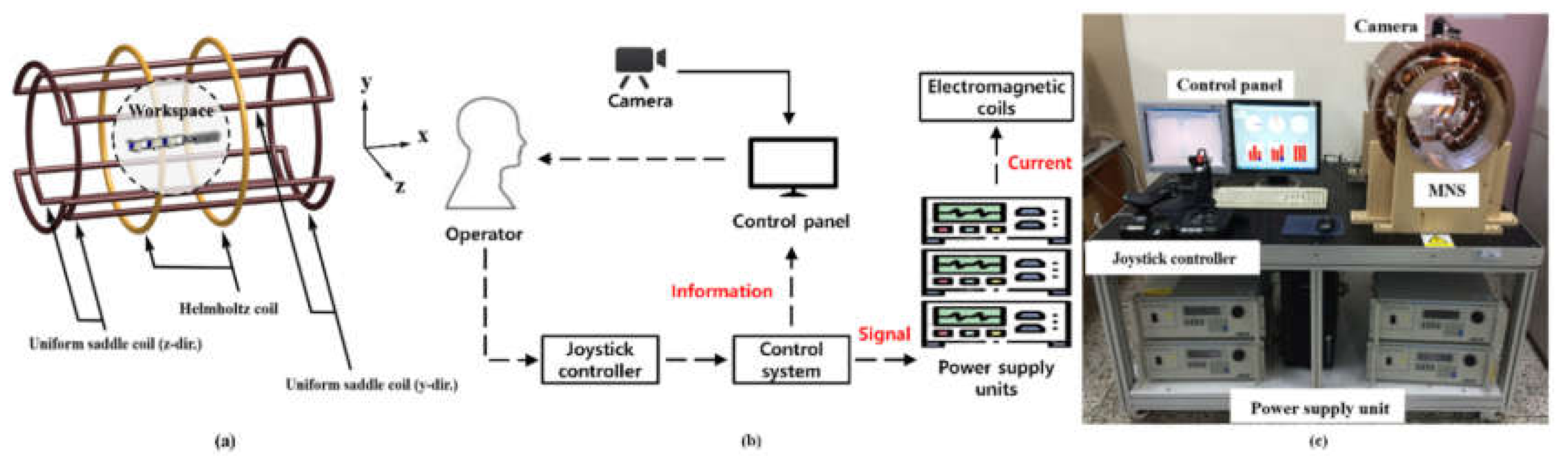
We developed a magnetic navigation system to control the various motions of the CMR. As shown in Figure 2a, the MNS is composed of three coils, i.e., a Helmholtz coil that generates a uniform magnetic field along the x-axis, a y-directional uniform saddle coil that generates a uniform magnetic field along the y-axis, and a z-directional uniform saddle coil that generates a uniform magnetic field along the z-axis. Moreover, the CMR is controlled inside of the workspace which is in a magnetic field controlled by a Helmholtz coil and two uniform saddle coils. Because the external magnetic fields generated by each coil of the MNS are orthogonal to one another, the MNS can create a three-dimensional external magnetic field. The external magnetic field generated from the MNS can be expressed as the following equation [23]:
where i, n, and r are the current, the number of coil turns, and the radius of the coil, respectively. The subscripts h, uy, and uz represent the Helmholtz coil, y-directional uniform saddle coil, and z-directional uniform saddle coil, respectively. The coefficients are only affected by the permeability of the medium in the workspace. Figure 2b shows the workflows of the system. Operators can monitor the orientation and motions of the CMR via camera and the information of the applied magnetic field, such as magnitude, direction, and frequency, through the control panel. When the operator manipulates the joystick to control the motions of the CMR, the signals generated by the joystick are converted into current information and then transmitted to the power supplies connected to the pairs of electromagnetic coils that generate the magnetic field. Figure 2c depicts a constructed MNS and experimental setup.
The magnetic torque, T, exerted on a permanent magnet due to the magnetic field can be expressed as follows:
where m and B are the magnetic moment of a permanent magnet and the magnetic flux density of the external magnetic field generated by the current flowing through the coil or by other permanent magnets.
3.2. Crawling Motion under External Precessional Magnetic Field
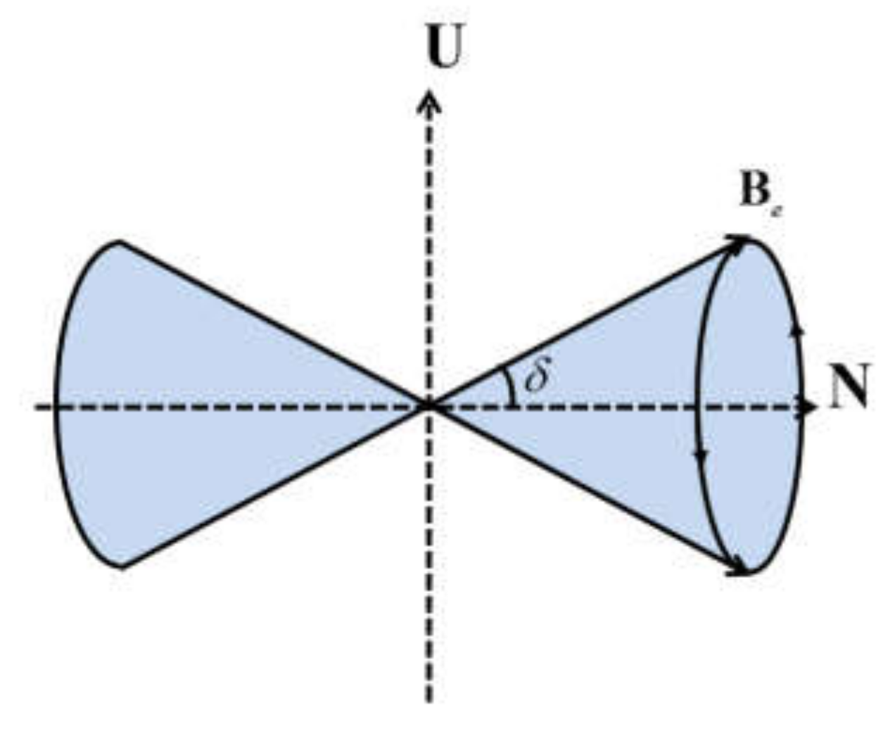
Figure 3 shows the external precessional magnetic field used to control the crawling motion of the CMR. The external precessional magnetic field can be expressed as follows:
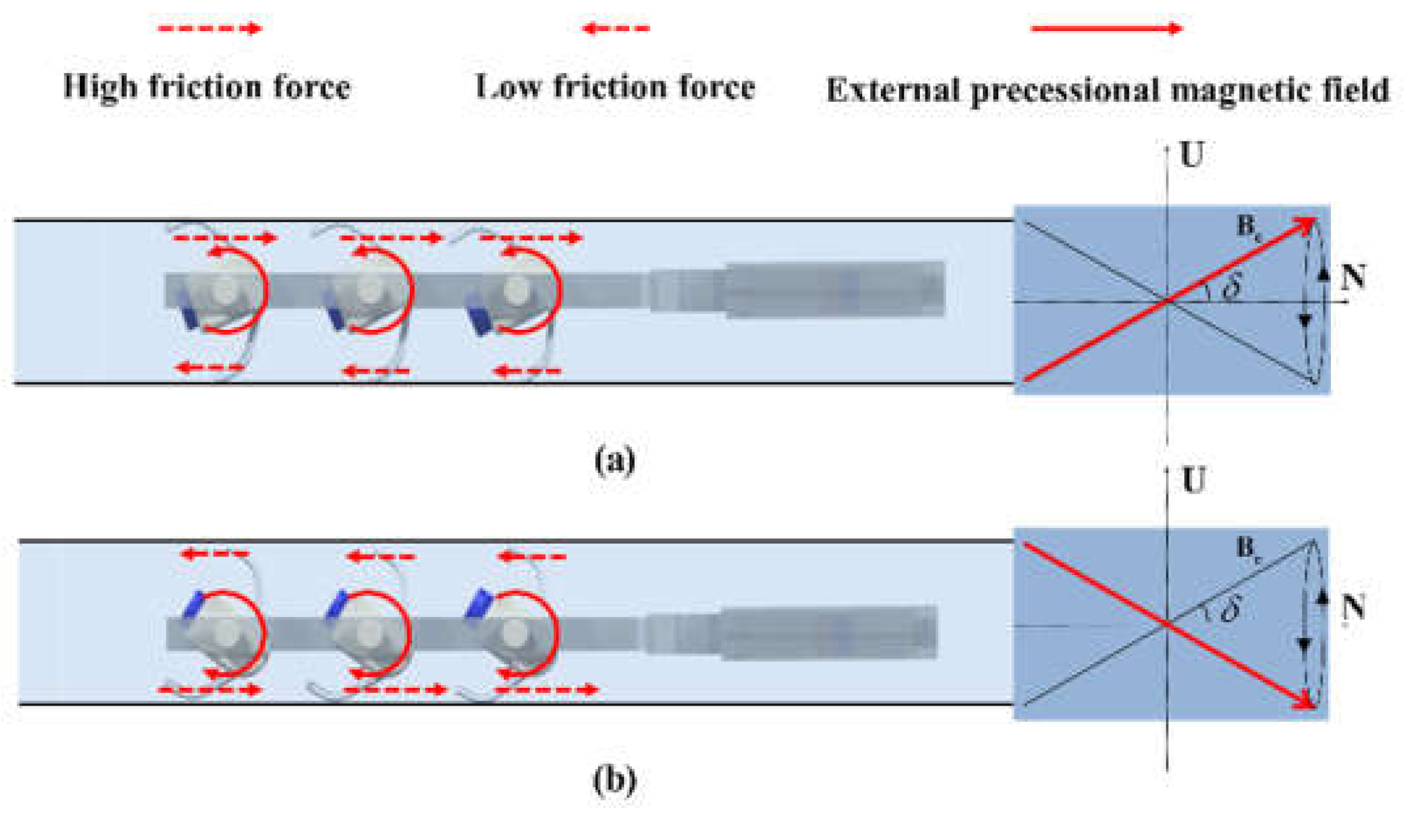
where Be, δ, f, N, and U are the magnitude, precessional angle, rotational frequency of the external precessional magnetic field, a unit vector of the rotating axis, and a unit vector normal to N. The CMR performs a crawling motion using an external precessional magnetic field to reach the target location along the tubular environment. The magnetic torque of Equation (2) is generated in the CM by the external precessional magnetic field of Equation (3), and the repetitive oscillation of the crawling bodies is generated by this magnetic torque. In this process, the angle of the oscillation is determined by the precession angle (δ). Due to this oscillation, as shown in Figure 4, the asymmetric frictional force between the flexible leg and the wall of the tubular environment is formed to generate the propulsive force of the CMR [20].
As shown in Figure 4a, when the crawling body rotates counterclockwise, positive frictional force is generated in the upper flexible leg, and negative frictional force is generated in the lower flexible leg. The positive friction force is greater than the negative friction force, so that the CMR moves forward. Figure 4b shows that the crawling body rotates clockwise to the opposite direction. Then, the CMR moves forward by the same mechanism, as shown in Figure 4a. However, the propulsive force generated by the asymmetric friction force is degraded when the external oscillating magnetic field is not parallel to the driving plane. To constantly apply the oscillating external magnetic field even in any posture of the CMR, we applied an external precessional magnetic field as shown in Figure 3. Furthermore, the CMR can change its direction of movement by the rotation of a uniform magnetic field with respect to the y-axis by 180°. The design factors affecting the crawling motion are the magnitude, precessional angle, and rotational frequency of the external precessional magnetic field [21].
3.3. Uncovering and Covering Motion of a Biopsy Needle
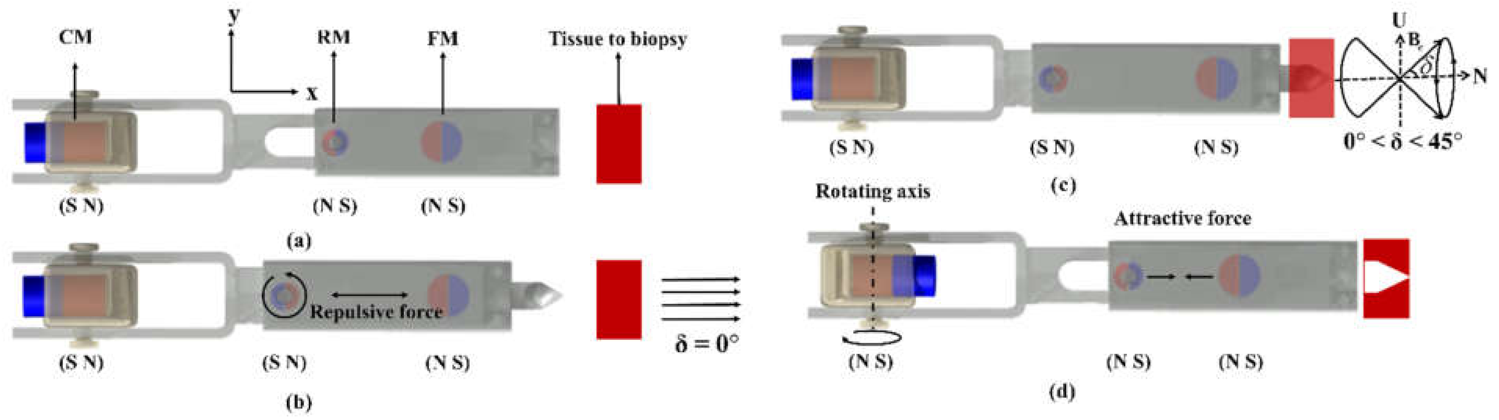
Figure 5 shows the operation to control the uncovering and covering motion of a biopsy needle before performing the biopsy. Figure 5a shows the posture of the CMR and the permanent magnets during navigation before reaching a target area. In this posture, there is an attractive force between the RM and FM and a repulsive force between the CM and RM, which closes the cover. When an external magnetic field with δ = 0° is applied to the CMR, as shown in Figure 5b, the magnetic torque is exerted on the RM. Once the magnetic torque exerted on the RM by the external magnetic field is greater than the magnetic torque exerted on the RM by the FM and CM, the RM rotates to the same direction as the external magnetic field, as shown in Figure 5b. Since the angle between the RM and the external magnetic field is theoretically zero, the magnetic torque exerted on the RM by the external magnetic field should be zero, as explained in Equation (2). However, while the CMR navigates along the tube by the external precessional magnetic field, the RM cannot be positioned straight along the direction of movement because the RM oscillates. Thus, a magnetic torque exerted on the RM by the external magnetic field causes the RM to rotate. In the posture of Figure 5b, a repulsive force is generated between the RM and FM, the cover connected to the RM is uncovered, and the biopsy needle is exposed. Figure 5c shows the puncturing process of the CMR into the target tissue by the crawling motion generated by the external precessional magnetic field (0° < δ < 45°). Finally, Figure 5d shows the rotation of a crawling body and flexible leg along the y-axis after a uniform magnetic field is applied along the y-axis for 180°. Then, the magnetic field generated by the CM and FM exerts a magnetic torque on the RM in the same direction, which makes the RM rotate another 180°. In this posture, the attractive force between the RM and FM, which is greater than the attractive force between the RM and CM, closes the cover. Once the needle is covered, the sampled tissue can be safely carried out to the destination because the external precessional magnetic field used for the crawling motion does not affect the biopsy part.
4. Design and Fabrication of the CMR
4.1. Design of the Crawling Part
To design the CMR, we considered the magnetic force and torque generated by the interaction of the magnets (CMs, RM, and FM) of the CMR as well as the magnetic torque generated by the external magnetic field. The magnetic field generated by the permanent magnet is represented by a point–dipole model as follows:
where μ0, R, and R are the permeability of air, a vector from the permanent magnet to a point, and the magnitude of R, respectively.
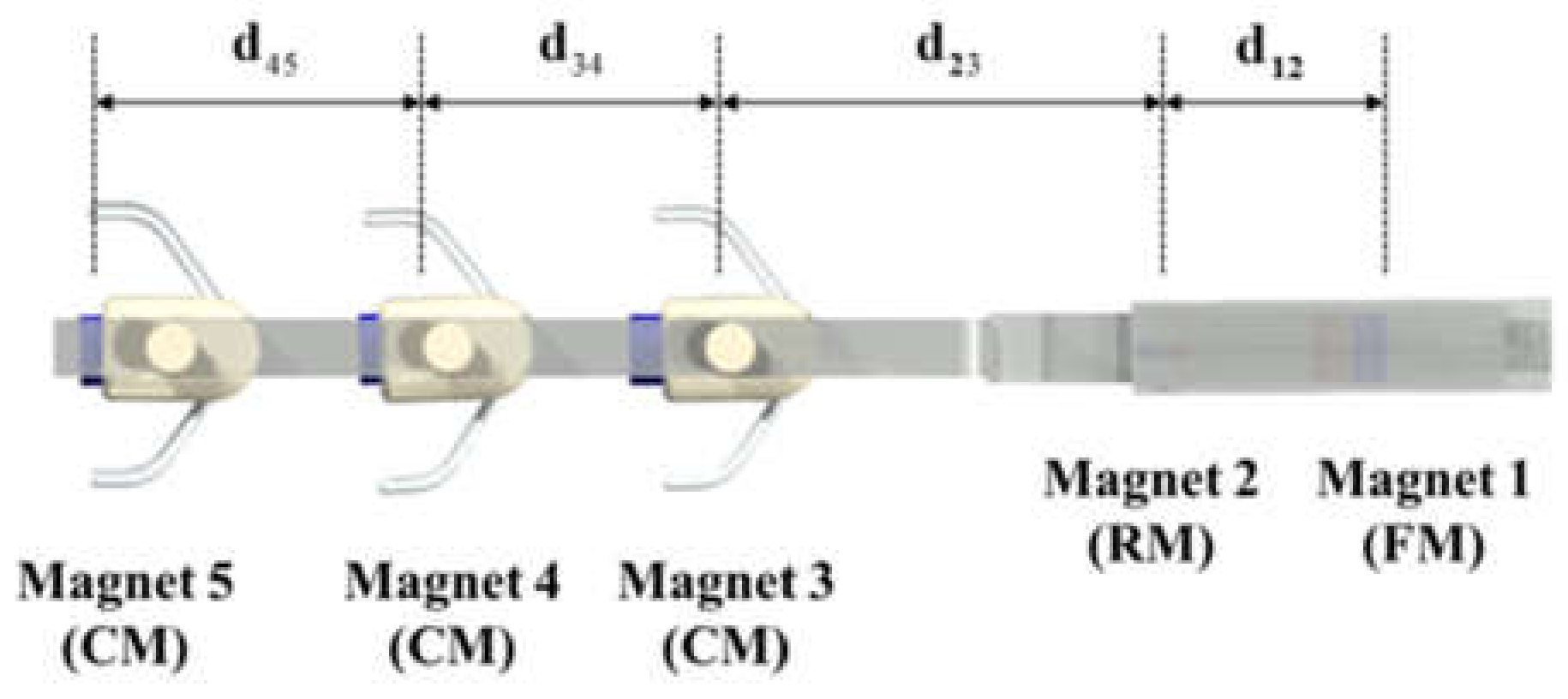
For the crawling part, the magnetic torque exerted on the CM by the external magnetic field should be greater than the magnetic torque exerted on the CM by other CMs for the crawling body to oscillate freely along the y-axis due to the external magnetic field. Since this is mostly determined by the distance between CMs, it is necessary to design the intervals between crawling bodies. Figure 6 shows the FM, RM, and CMs as magnets 1, 2, 3, 4, and 5, in order, and the distances between each pair of magnets are defined as d12, d23, d34, and d45. To determine the spacing between the crawling bodies, the magnetic torque due to the external magnetic field must be greater than the internal magnetic torque between the CMs. In this paper, we ignored the influence of magnets 1 and 2 on magnets 3, 4, and 5. One major reason is that the volumes of the magnets 1 (FM) and 2 (RM) are smaller than those of the magnets 3, 4, and 5 (CMs), because we sought to use a small external magnetic field for navigation. Therefore, the spacing between the crawling bodies should be determined to satisfy the following torque constraint:
where Te and Ti are the external magnetic torque and internal magnetic torque exerted on CM, respectively. Utilizing Equation (5), the minimum lengths of d34 and d45 between the crawling bodies can be determined as follows [20]:
Once we determined the size of the CM, as listed in Table 1 and the external magnetic flux density generated from MNS as in Figure 2 to be 8 mT for the crawling motion, the calculated result for d34 and d45 was 13 mm for this study. We also determined the length of the legs to be 12.5 mm, because they can rotate 180° through the slots between the CMs to change the direction of movement.
4.2. Design of the Biopsy Part
To design the biopsy part, we considered the torque and force constraints between the CM, FM, RM, and external magnetic field during the uncovering motion, biopsy, and covering motion. To keep the cover closed during the crawling motion, as shown in Figure 5a, the magnetic torque exerted on RM should satisfy the following equation:
where Te, T21, and T23 are the magnetic torque exerted on the RM by the external magnetic field, the torque exerted on the RM by the FM, and the torque exerted on the RM by the CM (magnet 3). In this situation, an attractive force between the RM and FM and a repulsive force between the RM and CM are generated to keep the cover closed.
To perform an uncovering motion, we increase the external magnetic field, as shown in Figure 5b, in such a way, that the magnetic torque exerted on the RM satisfies the following equation:
Once Equation (8) is satisfied, the RM rotates 180° in the same direction as the external magnetic field, which generates the repulsive force between the RM and the FM. This repulsive force opens the cover, and the biopsy needle is exposed. Then, we apply the external precessional magnetic field, as shown in Figure 5c, to generate a crawling motion to puncture the tissue. After the needle is inserted into the tissue, we rotate the uniform magnetic field with respect to the y-axis by 180° to rotate the CMs. This rotates the direction of movement of the crawling body and flexible legs to the opposite direction; at the same time, the polarity of the RM changes, as shown in Figure 5d, due to the attractive forces between the CM and RM and between the RM and FM. However, the attractive force between the RM and FM should be greater than that between the CM and RM to close the cover as follows:
where F21 and F23 are the magnetic attractive force exerted on the RM by the FM and the magnetic attractive force exerted on the RM by the CM (magnet 3).
After we designed the CMs, the spacing between CMs, the length of legs, and the minimum magnetic field for the crawling motion described in Section 4.1, we determined d23 to be 18.5 mm, which includes the rotational space for the flexible leg to change the direction of movement (12.5 mm), the opening and closing space for the cover to perform the uncovering and covering motions (4 mm), and the thickness of the biopsy structure required for three-dimensional (3D) printing (2 mm). We designed the RM, the FM, and d12 in such a way that Equations (7)–(9) are satisfied for the crawling motion with the safely covered needle, the uncovering motion to expose the needle, and the motion to cover the needle and collected sample, respectively.
Once we determined the external magnetic field for navigation to be 8 mT, which is derived in Section 4.1, we selected the RM in such a way that the magnetic field from the RM does not interfere with the magnetic field of the CM so as not to affect the crawling motion adversely. The magnetic moment of the RM, as listed in Table 1, is only 4.5% of the CM. We also selected an FM sufficient to satisfy Equation (7), and the magnetic moment of the FM, as listed in Table 1, is 50% of the CM. Figure 7a shows the net magnetic torque exerted on the RM, as shown in Equation (7), according to the length of d12. It shows that Equation (7) is satisfied when d12 is less than 8 mm. For the uncovering motion to expose the needle as shown in Equation (8), Figure 7b shows the net magnetic torque exerted on the RM according to the magnitude of the external magnetic field when d12 is 8 mm. It shows that Equation (8) is satisfied when the magnetic field is greater than 8 mT. For the motion covering the biopsy needle and collected sample, Equation (9) is always satisfied when d12 = 8 mm (F21 − F23 = 1 mN). Table 1 shows the major design variables of CMR determined through this design process.
4.3. Assembly of the CMR
We prototyped all components of the CMR using 3D printing technology except for the legs and magnets. The crawling legs are made of silicone rubber, and all magnets are NdFeB (N52) with a magnetization of 1,130,000 A/m. Figure 8 shows the components of the CMR and the assembled CMR.
5. Experiment and Verification
5.1. Verification of Puncturing Force
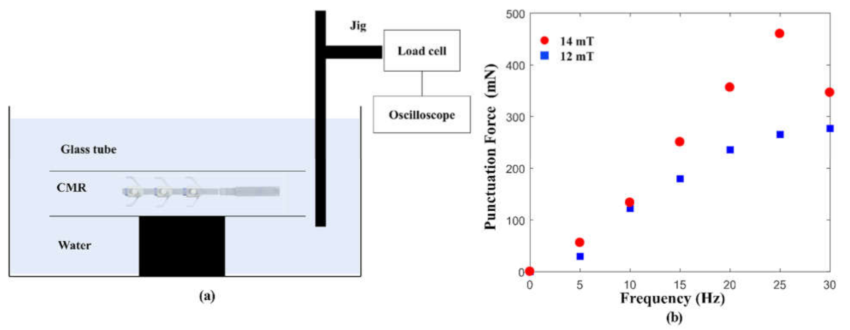
The proposed CMR should generate a puncturing force sufficient to insert a needle into the tissue to collect sample tissue. According to Yang et al. [24], a minimum force of 0.3 N is required to puncture the liver tissue of pigs. Figure 9a shows an experimental setup to measure the propulsive force of the CMR. First, the pseudo-glass tube containing the CMR was fixed in a water container, and a jig connected to the load cell (Honeywell, Morris Plains, NJ, USA) was placed in front of the pseudo-glass tube. The experimental setup was then placed inside the MNS. Once the external precessional magnetic field generated from the MNS was applied to the CMR for 5 s, the propulsive force of the crawling CMR was measured by the load cell. Figure 9b shows the maximum magnitude of the propulsive force according to the rotational frequency of the external precessional magnetic field when the magnitude of the external precessional magnetic field is 12 and 14 mT, respectively. When the magnitude of the external precessional magnetic field was 12 mT, the puncturing force increased with the increase in the rotational frequency. However, the puncturing force did not increase by more than 280 mN even if the rotational frequency increased beyond 25 Hz. When the magnitude of the external precessional magnetic field was 14 mT, the puncturing force also increased with the increase in the rotational frequency. However, when the rotational frequency of the external magnetic field was over 30 Hz, the puncturing force decreased because of the step-out phenomenon, in which the crawling body cannot follow the rotational frequency of the external precessional magnetic field. As shown in Figure 9b, the puncturing force was 0.46 N when the magnitude and the rotational frequency of the external precessional magnetic field were 14 mT and 25 Hz. We confirmed that the proposed CMR can generate a puncturing force sufficient for the biopsy needle to be inserted into the liver tissue of pigs.
5.2. Verification of Uncovering and Covering Motions for Selective Biopsy
Opening and closing the cover of the CMR is controlled by the magnitude of the external magnetic field and the force formed between the two magnets, the RM and FM. To verify the uncovering motion, we increased the external magnetic field, as shown in Figure 5b, and we observed the rotation of the RM according to the magnitude of the external magnetic field. This experiment was repeated 10 times, and the RM rotated 4 times when the external magnetic field was 8.5 mT, 4 times when it was 9 mT, and 2 times when it was 9.5 mT. The magnitude of the external magnetic field is designed to open the cover when the external magnetic field is greater than 8 mT. However, the uncovering motion was observed when the magnitude of the external magnetic field was between 8.5 mT and 9.5 mT due to the friction between the module body and the cover.
To verify the covering motion, we increased the rotating uniform magnetic field along the negative y-axis, as shown in Figure 5d, to observe the turning motions of the crawling bodies and legs of the CMR. The minimum rotating magnetic field was measured to be 8 mT to change the direction of movement of the CMR. In this posture, the magnetic field generated by the CM and FM exerts a magnetic torque on the RM in the same direction, which makes the RM rotate 180°. At the same time, the attractive force between the RM and FM is greater than the attractive force between the RM and CM, which allows the needle to be covered. Through these experiments, we confirmed that the cover of the CMR could be selectively opened and closed by controlling the external magnetic field.
5.3. Experiment in Y-Shaped, Water-Filled Tubular Environment
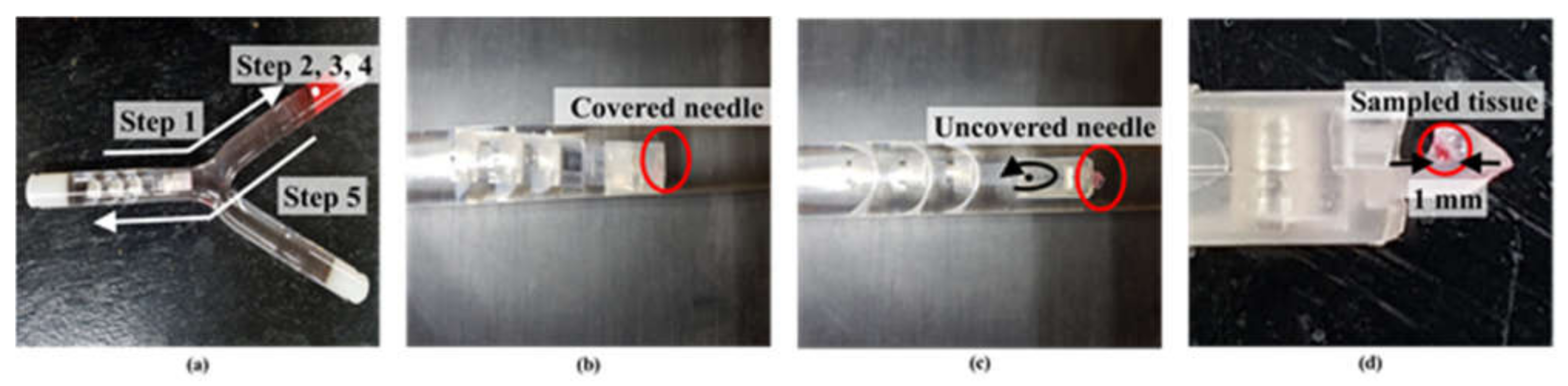
To evaluate the crawling motion and biopsy performance of the CMR, we used a pseudo-tissue made of agar filled at one end of a Y-shaped watery glass tube with a diameter of 14 mm, as shown in Figure 10a. In step 1, the CMR crawled to a target point, propelled by the external precessional magnetic field (B = 8 mT, f = 15 Hz, δ = 30°), and the cover was closed during navigation as shown in Figure 10b. In the bifurcated branch, we controlled the joystick to change the unit vector of the rotating axis (N), which can be accomplished by controlling the applied currents of the developed MNS. In step 2, the cover was opened by a uniform magnetic field of 12 mT. In step 3, the uncovered biopsy needle punctured the tissue by the crawling motion generated by the external precessional magnetic field (B = 14 mT, f = 25 Hz, δ = 30°). In step 4, the turning motions of the crawling bodies and flexible legs along the y-axis as well as the covering motion of the biopsy needle were performed by rotating the uniform magnetic field of 12 mT by 180° along the y-axis. Finally, in step 5, the CMR crawled back to the original point, propelled by the external precessional magnetic field (B = 12 mT, f = 15 Hz, δ = 30°). Figure 10c shows the uncovered needle before the biopsy needle was inserted into the pseudo-tissue. Figure 10d shows a sampled tissue of 1 mm thickness extracted through this experiment. We confirmed from this experiment that the proposed CMR could crawl through a tubular structure and extract sample tissue successfully.
6. Concluding Remarks
We developed a CMR that can navigate through a tubular environment, control uncovering and covering motions of the biopsy needle, and extract sample tissue by utilizing an external magnetic field. The proposed CMR has the advantage of being able to use the needle selectively and safely via an external magnetic field. We proposed a design method and prototyped the proposed CMR using 3D printing technology. The mechanism of covering and uncovering motions utilized attractive and repulsive forces of magnets under external magnetic field. CMR is designed to navigate under 8 mT of external magnetic field. The puncturing force of the CMR was 0.46 N in 14 mT of external magnetic field, which satisfies the minimum force needed for biopsy. We verified experimentally the uncovering and covering motions of the cover and the ability of the CMR to extract tissue with the biopsy needle in a Y-shaped water-filled tubular environment.
There are several future research areas of the proposed CMR to be applied to the human body. First, the CMR needs to be downsized in order to be able to navigate even through the blood-vessel environments. The size of the proposed CMR allows it to be applied to the common iliac artery or small intestine. Second, the structure of the proposed CMR needs to be improved considering the friction, flexibility, and shape of the tubular system of the human body and the pulsating blood flow. Third, a tracking system of the CMR is needed to identify the position and motion of the CMR inside the human body. Current X-ray imaging cannot detect the structures of the CMR except for the magnets. As a starting mechanism, we expect that the proposed CMR can contribute to extending magnetic robot applications in various medical fields.
Author Contributions
Project administration and Funding acquisition, G.J.; Investigation, E.J. and J.N.; Methodology, E.J. and J.N.; Validation, E.J. and W.L.; Visualization, E.J., W.L. and J.K.; Writing—original draft, E.J.; Writing—review & editing, G.J. All authors have read and agreed to the published version of the manuscript.
Funding
This research was supported by a grant of the Korea Health Technology R&D Project through the Korea Health Industry Development Institute (KHIDI), funded by the Ministry of Health and Welfare, Republic of Korea (grant number: HI19C1055).
Institutional Review Board Statement
Not applicable.
Informed Consent Statement
Not applicable.
Data Availability Statement
No new data were created or analyzed in this study.
Conflicts of Interest
The authors declare no conflict of interest. The funders had no role in the design of the study; in the collection, analyses, or interpretation of data; in the writing of the manuscript, or in the decision to publish the results.
References
- Rizzo, J.; Bernstein, D.; Gress, F. A performance, safety and cost comparison of reusable and disposable endoscopic biopsy forceps: A prospective, randomized trial. Gastrointest. Endosc. 2000, 51, 257–261. [Google Scholar] [CrossRef]
- Marr, K.A. Catheter-related bacteremia and outcome of attempted catheter salvage in patients undergoing hemodialysis. Ann. Intern. Med. 1997, 127, 275. [Google Scholar] [CrossRef] [PubMed]
- Brun-Buisson, C.; Doyon, F.; Carlet, J. Bacteremia and severe sepsis in adults: A multicenter prospective survey in ICUs and wards of 24 hospitals. French bacteremia-sepsis study group. Am. J. Respir. Crit. Care Med. 1996, 154, 617–624. [Google Scholar] [CrossRef] [PubMed]
- Samore, M.H.; Wessolossky, M.A.; Lewis, S.M.; Shubrooks, S.J., Jr.; Karchmer, A.W. Frequency, risk factors, and outcome for bacteremia after percutaneous transluminal coronary angioplasty. Am. J. Cardiol. 1997, 79, 873–877. [Google Scholar] [CrossRef]
- Park, S.; Koo, K.; Bang, S.M.; Park, J.Y.; Song, S.Y.; Cho, D. ‘Dan’ A novel microactuator for microbiopsy in capsular endoscopes. J. Micromech. Microeng. 2008, 18, 025032. [Google Scholar] [CrossRef]
- Pan, G.; Wang, L. Swallowable wireless capsule endoscopy: Progress and technical challenges. Gastroenterol. Res. Pract. 2011, 2012, e841691. [Google Scholar] [CrossRef] [Green Version]
- Moglia, A.; Menciassi, A.; Schurr, M.O.; Dario, P. Wireless capsule endoscopy: From diagnostic devices to multipurpose robotic systems. Biomed. Microdevices 2007, 9, 235–243. [Google Scholar] [CrossRef]
- Microrobots for minimally invasive medicine. Annu. Rev. Biomed. Eng. 2010, 12, 55–85. [CrossRef] [Green Version]
- Sitti, M.; Ceylan, H.; Hu, W.; Giltinan, J.; Turan, M.; Yim, S.; Diller, E. Biomedical applications of untethered mobile milli/microrobots. Proc. IEEE 2015, 103, 205–224. [Google Scholar] [CrossRef]
- Choi, H.; Choi, J.; Jang, G.; Park, J.; Park, S. Two-dimensional actuation of a microrobot with a stationary two-pair coil system. Smart Mater. Struct. 2009, 18, 055007. [Google Scholar] [CrossRef]
- Wen, L.; Wang, T.; Wu, G.; Liang, J.; Wang, C. Novel method for the modeling and control investigation of efficient swimming for robotic fish. IEEE Trans. Ind. Electron. 2012, 59, 3176–3188. [Google Scholar] [CrossRef]
- Jeon, S.M.; Jang, G.H.; Choi, H.C.; Park, S.H.; Park, J.O. Magnetic navigation system for the precise helical and translational motions of a microrobot in human blood vessels. J. Appl. Phys. 2012, 111, 07E702. [Google Scholar] [CrossRef] [Green Version]
- Kim, S.H.; Hashi, S.; Ishiyama, K. Hybrid magnetic mechanism for active locomotion based on inchworm motion. Smart Mater. Struct. 2013, 22, 027001. [Google Scholar] [CrossRef]
- Fukushi, T.; Kim, S.H.; Hashi, S.; Ishiyama, K. Preliminary validation of Sm–Fe–N magnetic silicone rubber for a flexible magnetic actuator. Smart Mater. Struct. 2014, 23, 067001. [Google Scholar] [CrossRef]
- Yim, S.; Goyal, K.; Sitti, M. Magnetically actuated soft capsule with the multimodal drug release function. IEEE/ASME Trans. Mechatron. 2013, 18, 1413–1418. [Google Scholar] [CrossRef] [Green Version]
- Choi, H.; Cha, K.; Jeong, S.; Park, J.; Park, S. 3-D locomotive and drilling microrobot using novel stationary EMA system. IEEE/ASME Trans. Mechatron. 2013, 18, 1221–1225. [Google Scholar] [CrossRef]
- Nam, J.; Jeon, S.; Kim, S.; Jang, G. Crawling microrobot actuated by a magnetic navigation system in tubular environments. Sens. Actuators A Phys. 2014, 209, 100–106. [Google Scholar] [CrossRef]
- Jeon, S.; Jang, G. Precise manipulation of a microrobot in the pulsatile flow of human blood vessels using magnetic navigation system. J. Appl. Phys. 2011, 109, 07B316. [Google Scholar] [CrossRef]
- Lee, W.; Jeon, S.; Nam, J.; Jang, G. Dual-body magnetic helical robot for drilling and cargo delivery in human blood vessels. J. Appl. Phys. 2015, 117, 17B314. [Google Scholar] [CrossRef] [Green Version]
- Lee, W.; Nam, J.; Kim, J.; Jung, E.; Jang, G. Effective locomotion and precise unclogging motion of an untethered flexible-legged magnetic robot for vascular diseases. IEEE Trans. Ind. Electron. 2018, 65, 1388–1397. [Google Scholar] [CrossRef]
- Kim, S.; Jang, G.; Jeon, S.; Nam, J. A crawling and drilling microrobot driven by an external oscillating or precessional magnetic field in tubular environments. J. Appl. Phys. 2015, 117, 17A703. [Google Scholar] [CrossRef]
- Lee, W.; Nam, J.; Jang, B.; Jang, G. Selective motion control of a crawling magnetic robot system for wireless self-expandable stent delivery in narrowed tubular environments. IEEE Trans. Ind. Electron. 2017, 64, 1636–1644. [Google Scholar] [CrossRef]
- Jeon, S.; Jang, G.; Choi, H.; Park, S. Magnetic navigation system with gradient and uniform saddle coils for the wireless manipulation of micro-robots in human blood vessels. IEEE Trans. Magn. 2010, 46, 1943–1946. [Google Scholar] [CrossRef]
- Yang, H.; Liu, P.X.; Zhang, J. Modelling of needle insertion forces for surgical simulation. In Proceedings of the IEEE International Conference Mechatronics and Automation, Niagara Falls, ON, Canada, 29 July–1 August 2005; Volume 2, pp. 592–595. [Google Scholar]
Figure 1.
(a) Proposed CMR composed of a crawling part and a biopsy part. (b) Structure of crawling body. (c) Structure of biopsy part.
Figure 1.
(a) Proposed CMR composed of a crawling part and a biopsy part. (b) Structure of crawling body. (c) Structure of biopsy part.

Figure 2.
(a) MNS composed of a Helmholtz coil and two uniform saddle coils to generate an external precessional magnetic field. (b) Control workflows of the MNS. (c) Constructed MNS and experimental setup.
Figure 2.
(a) MNS composed of a Helmholtz coil and two uniform saddle coils to generate an external precessional magnetic field. (b) Control workflows of the MNS. (c) Constructed MNS and experimental setup.

Figure 3.
External precessional magnetic field to control the CMR.

Figure 4.
Principle of crawling motion with an external precessional magnetic field. (a) Counterclockwise rotation of the crawling body. (b) Clockwise rotation of the crawling body.
Figure 4.
Principle of crawling motion with an external precessional magnetic field. (a) Counterclockwise rotation of the crawling body. (b) Clockwise rotation of the crawling body.

Figure 5.
(a) CMR with needle covered to reach a target area. (b) Uncovering motion of CMR to expose the needle. (c) Crawling motion to puncture the tissue with external precessional magnetic field. (d) CMR with covered needle and collected sample heading backward to return to the starting point.
Figure 5.
(a) CMR with needle covered to reach a target area. (b) Uncovering motion of CMR to expose the needle. (c) Crawling motion to puncture the tissue with external precessional magnetic field. (d) CMR with covered needle and collected sample heading backward to return to the starting point.

Figure 6.
Distances between the magnets in the CMR.

Figure 7.
(a) The net magnetic torque on the RM for different distances between the RM and FM when the external magnetic field was 8 mT. (b) The net magnetic torque on the RM in different external magnetic fields when the distance between the RM and FM was 8 mm.
Figure 7.
(a) The net magnetic torque on the RM for different distances between the RM and FM when the external magnetic field was 8 mT. (b) The net magnetic torque on the RM in different external magnetic fields when the distance between the RM and FM was 8 mm.

Figure 8.
(a) Components of the CMR. (b) Assembled CMR.

Figure 9.
(a) Experimental setup to measure the puncturing force of CMR. (b) Puncturing force of CMR according to frequency and external magnetic field.
Figure 9.
(a) Experimental setup to measure the puncturing force of CMR. (b) Puncturing force of CMR according to frequency and external magnetic field.

Figure 10.
(a) Experiment testing the crawling and biopsy motions. (b) Covered needle. (c) Uncovered needle. (d) Collected sample tissue.
Figure 10.
(a) Experiment testing the crawling and biopsy motions. (b) Covered needle. (c) Uncovered needle. (d) Collected sample tissue.


Table 1.
Design variables of the CMR.
| Name | Variable | Value |
|---|---|---|
| Distance between magnets | d12 | 8.0 mm |
| d23 | 18.5 mm | |
| d34 | 13.0 mm | |
| d45 | 13.0 mm | |
| Fixed cylindrical magnet | Diameter | 3.0 mm |
| Length | 3.0 mm | |
| Grade | N52 | |
| Magnetic moment | 0.0245 | |
| Rotating ring magnet | Outer diameter | 2.0 mm |
| Inner diameter | 1.0 mm | |
| Length | 0.8 mm | |
| Grade | N52 | |
| Magnetic moment | 0.0022 | |
| Crawling magnet | Diameter | 3.0 mm |
| Length | 6.0 mm | |
| Grade | N52 | |
| Magnetic moment | 0.0490 | |
| Flexible leg | Length | 25 mm |
Publisher’s Note: MDPI stays neutral with regard to jurisdictional claims in published maps and institutional affiliations. |
© 2021 by the authors. Licensee MDPI, Basel, Switzerland. This article is an open access article distributed under the terms and conditions of the Creative Commons Attribution (CC BY) license (https://creativecommons.org/licenses/by/4.0/).
Share and Cite
MDPI and ACS Style
Jung, E.; Nam, J.; Lee, W.; Kim, J.; Jang, G. Crawling Magnetic Robot to Perform a Biopsy in Tubular Environments by Controlling a Magnetic Field. Appl. Sci. 2021, 11, 5292. https://0-doi-org.brum.beds.ac.uk/10.3390/app11115292
AMA Style
Jung E, Nam J, Lee W, Kim J, Jang G. Crawling Magnetic Robot to Perform a Biopsy in Tubular Environments by Controlling a Magnetic Field. Applied Sciences. 2021; 11(11):5292. https://0-doi-org.brum.beds.ac.uk/10.3390/app11115292
Chicago/Turabian StyleJung, Eunsoo, Jaekwang Nam, Wonseo Lee, Jongyul Kim, and Gunhee Jang. 2021. "Crawling Magnetic Robot to Perform a Biopsy in Tubular Environments by Controlling a Magnetic Field" Applied Sciences 11, no. 11: 5292. https://0-doi-org.brum.beds.ac.uk/10.3390/app11115292
Note that from the first issue of 2016, this journal uses article numbers instead of page numbers. See further details here.